Abstract
All-solid-state Li-S batteries (use of solid electrolyte LiBH4) were prepared using cathodes of a homogeneous mixture of graphene oxide (GO) and reduced graphene oxide (rGO) with sulfur (S) and solid electrolyte lithium borohydride (LiBH4), and their electrochemical performance was reported. The use of LiBH4 and its compatibility with Li metal permits the utilization of Li anode that improves the vitality of composite electrodes. The GO-S and rGO-S nanocomposites with different proportions have been synthesized. Their structural and morphological characterizations were performed by X-ray diffraction (XRD) and scanning electron microscopy (SEM), and the results are presented. The electrochemical performance was tested by galvanostatic charge-discharge measurements at a 0.1 C-rate. The results presented here demonstrate the successful implementation of GO-S composites in an all-solid-state battery.
1. Introduction
Lithium-sulfur (Li-S) batteries have attracted attention all over the world for the future energy needs due to the material’s low cost, easy availability, non-hazardous nature and high specific capacity of about 1675 mAh/g with a high theoretical specific energy density of 2600 Wh/kg [1,2]. However, Li-S batteries are progressing slowly due to polysulfide (PS) and dendrite formation, which significantly abbreviates the cycling life and raises safety issues for Li-S batteries [3,4,5,6,7,8]. To overcome these issues, the trapping of sulfur inside the porous carbon material matrix with different arrangements (for example, graphene, graphene oxide, porous carbon, and carbon nanotubes) were employed [9,10,11,12]. Out of these, GO and rGO have attracted extensive consideration [13,14,15,16,17] due to their stability, lightweight, enormous surface territory, high electrical conductivity, incredible adaptability, and mechanical properties compared to other carbon materials [18,19]. GO can easily be deposited on the surface of the material and binds it due to its hydrophilic nature as it contains more oxygen contents as compared to graphene. The rGO can be obtained from GO by washing it with hydrogen hydrate, which reduces the oxygen content in rGO as compared to GO, which makes it more conductive and is helpful to achieve better performance in Li-ion battery. The unique construction of GO-S nanocomposite electrodes improves the performance of Li-S batteries by adjusting volume expansion during electrochemical testing. Moreover, rGO, with its vast surface region alongside pervasive cavities, can set up better electronic contact with sulfur to prevent conglomeration for the smooth flow of ions through the material. Peng Yu et al. [20], in their experimental study, prepared an electrode material by reducing graphene through a solution-based technique to encapsulate sulfur inside reduced graphene sheets, which resulted in better charging–discharging of a cell with good cycle ability and capacity. Yu-Yun Hsieh et al. [21] supported that carbon materials provide a major contribution to overcoming shuttle phenomena by trapping polysulfides and also boost the cathode’s conductivity. This was accomplished by synthesizing three-dimensional graphene with oxygen functionalization to form a composite with sulfur, which demonstrates excellent electrochemical performance as compared to previous works.
Different types of polymer electrolytes and composite electrolytes with perovskite and oxides are drawing attention for their application in Li-S batteries to overcome the safety issue of liquid electrolytes. In context to this, LiBH4—a notable hydrogen storage material—has been studied as a promising electrolyte material for the fabrication of all-solid-state batteries. The phase transition of LiBH4 at ~115 °C provides high ionic conductivity (~1 mS/cm), which allows for its use as a solid electrolyte that supports the flow of lithium ions through it [22,23,24,25,26]. LiBH4 is safer to be used in comparison to liquid flammable electrolytes. It is quite stable up to 450 °C, after which it decomposes to LiH and B. In this work, LiBH4 is employed with the GO-S and rGO-S composite cathode material and lithium foil as an anode. The use of GO and rGO as an additive with sulfur in this work is expected to accommodate the volume expansion as a result of the expanded surface area and cushioning effect due to the GO and rGO network.
2. Materials and Methods
2.1. Synthesis of GO-S and rGO-S Nanocomposites
Hummer’s method [27] was used to synthesize the powdered GO, whereas rGO was obtained by chemical reduction of GO (washing of obtained GO with hydrogen hydrate to reduce oxygen content). The GO-S and rGO-S composites were synthesized via ball-milling for 1gm batch of composites that had different amounts of sulfur and GO/rGO, i.e., (i) S 99% and GO 1%, (ii) S 90% and GO 10%, (iii) S 99% and rGO 1%, and (iv) S 90% and rGO 10%. The milling was carried out for 24 h at 300 rpm using 20 stainless steel (SS) balls of 7 mm diameter.
2.2. Electrode Material Preparation
The electrode (Cathode) composite materials of GO-S and rGO-S were synthesized via ball-milling with LiBH4 and acetylene black (AB) in 40:30:30 weight proportion for 2 h, resting for 30 min after 1 h of milling under an argon environment. For the synthesis of a 200 mg sample (80 mg active material, i.e.,S-GO/rGO composite, 60 mg solid electrolyte LiBH4 and 60 mg AB), 10 SS balls were utilized at 370 rpm in a Fritsch P7 processing machine. LiBH4 and AB were both dried using a dynamic vacuum at 200 °C for 24 h before utilizing them to prepare the cathode.
2.3. Coin Cell Preparation
To test the electrochemical performance of the above-mentioned electrode materials, coin cells were fabricated with Li-foil as the anode, LiBH4 as the electrolyte, and the above-mentioned composites (S 99% and GO 1%, S 90% and GO 10%, S 99% and rGO 1%, and S 90% and rGO 10% with LiBH4 and AB) as the cathode layer. To fabricate the cell, a three-layer pellet was prepared by the following procedure. First, Li-foil (thickness of 0.14 mm) purchased from Honjo metal Co. Ltd., Osaka, Japan, in a circular shape was spread onto an SS plate as the first layer (thickness approx. 0.63 mm), then dried LiBH4 powder (~80 mg) was sprinkled and pressed under 10 MPa for 5 min using a hydraulic press machine. It was followed by spreading composite powder (~10 mg) as the 3rd layer and was pressed under 40 MPa for 5 min. The prepared 3-layered pellet was put in a coin cell case using a perfluoroalkoxy (PFA) gasket. The samples were kept completely isolated from atmospheric conditions throughout the investigation. All the handling was conducted inside a high-purity argon-filled glove box (oxygen and moisture content <0.1 ppm) to prevent the samples from contamination of oxygen.
2.4. Material Characterization and Electrochemical Measurements
X-ray diffraction (XRD) using the Rigaku-RINT 2500 with CuKα (λ = 1.5406 Å) as the radiation source was performed for all the samples within a 2θ range of 5°–50° at the scan speed 5°/min. The Debye Scherer formula was used to calculate the crystallite size D = 0.9λ/βcosθ, where λ = X-ray wavelength, θ = Bragg diffraction angle, β = full width at half maximum (FWHM).
Scanning electron microscopy (JEOL JSM-6380, JEOL Ltd., Tokyo, Japan) was used for surface morphology and energy dispersive spectroscopy (EDS) for elemental analysis. It is to note here that SEM/EDS observations were made on the top of the surface of the 3-layered pellet, which means that all the signals are from the cathode composite and not from the electrolyte layer (LiBH4) or the anode layer (Li foil). A charge–discharge analyzer (HJ1001SD8, Hokuto Denko Co.) was used for the measurement of electrochemical performance of the graphene modulated GO-S and rGO-S composite cathode with LiBH4 electrolyte at 0.1 C-rate and 120 °C temperatures.
3. Results and Discussion
3.1. X-ray Diffraction
Figure 1a,b shows X-ray diffraction spectra of GO-S and rGO-S composites with acetylene black (AB) and LiBH4. The individual curves are also shown in the Supplementary Materials for better clarity (Figures S1–S5). The diffraction peaks at 2θ = 22.9°, 25.9°, and 28.0°, which were indexed as (222), (026), and (040) planes, respectively. These represent the orthorhombic structure (JCPDS card no. 001-0478) of sulfur with high crystallinity [18]. The graphene oxide shows diffraction peaks at 2θ = 10.9° (001), 25.6° (002), and 43° (100). The GO-S and rGO-S composite with different wt% of GO and rGO showed all diffraction peaks as that for pristine sulfur, which confirms no phase transformation occurred due to GO and rGO in the composites. The detected characteristic peaks of S-GO and S-rGO composites match very well, demonstrating the orthorhombic structure. The presence of LiBH4 was confirmed in the composite material by the presence of peaks at 2θ = 17.7°,23.68°, 24.48°, 25.24°, 26.78°, 28.8°, and 40.32°. The average crystallite size of composites was 28 nm, as calculated by the Debye Scherer formula [11].
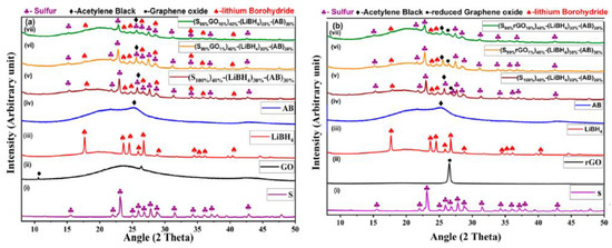
Figure 1.
XRD Plots of (a) electrode materials with (i) S, (ii) GO, (iii) LiBH4, (iv) AB, (v) (S100%)40%+(LiBH4)30%+(AB)30%, (vi) (S99%GO1%)40%+(LiBH4)30%+(AB)30%, and (vii) (S90%GO10%)40%+(LiBH4)30%+(AB)30%. (b) Electrode materials that have (i) S, (ii) rGO, (iii) LiBH4, (iv) AB, (v) (S100%)40%+(LiBH4)30%+(AB)30%, (vi) (S99%rGO1%)40%+(LiBH4)30%+(AB)30%, and (vii) (S90%rGO10%)40%+(LiBH4)30%+(AB)30%.
3.2. SEM Analysis
Figure 2a,b shows the SEM images of the top surface of the three-layer pellet, having a cathode composite part on the top, followed by the LiBH4 layer and the Li-foil layer of pristine and cycled (30 cycles) Li/GO-S/LiBH4 systems, respectively. Several major, as well as minor, cracks have been observed in the cycled system, which might be attributed due to the volume expansion and contraction during charging and discharging of the cell. The dynamics of the system, which further affects the battery performance, can be verified from Galvanostatic charge–discharge profiles. The system showed good capacity initially; however, the performance was degraded with the beginning of crack formation.
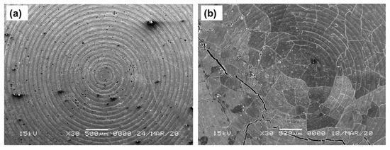
Figure 2.
SEM images of (a) Li/GO-S/LiBH4 system and (b) Cycled Li/GO-S/LiBH4 system (30 cycles).
Figure 3a–d shows EDS images of the GO-S composite electrode system(SEM image shown in Figure 2a), from which the uniform distribution of sulfur, carbon, and boron was seen with mapping percentages of 72.9%, 16.1%, and 6.1%, respectively, as calculated from Figure 3e. However, EDS spectra reflect Li in very small quantities in comparison to the expected content from LiBH4, which is due to the low energy of characteristic radiation of Li.

Figure 3.
EDS images of the electrode with GO-S showing elements: (a) Sulfur, (b) Lithium, (c) Boron, and (d) Carbon. (e) Mapping graph of the electrode with GO-S.
Figure 4a,b shows SEM images of the top surface of the 3-layer pellet, having the cathode composite part on the top, followed by the LiBH4 layer and the Li-foil layer of pristine and cycled (42 cycles) Li/rGO-S/LiBH4 systems, respectively. Although there is no direct evidence as SEM analysis was performed only after several cycles, by combining the SEM analysis and the cyclic charge-discharge profiles, it can be speculated that the majority of crack formation occurs during the initial cycling of the cell (the cell initially delivered better performance, which started degrading immediately as the crack formation occurred). On further cycling, these cracks started expanding more, thus resulting in fast capacity decay, as seen from electrochemical testing. These cracks affect the flow of Li-ions through the electrodes. As compared to the GO-S electrode, the rGO-S electrode exhibits less crack formation and suggests that the electrode may benefit in terms of the capacity and cycling performance of a battery. The addition of any carbon material is to accommodate the volume expansion and act as a binder for sulfur. The smaller cracks in rGO are due to the fact that it has a larger surface area than GO, so it can bind the electrode material (sulfur) more efficiently compared to GO.
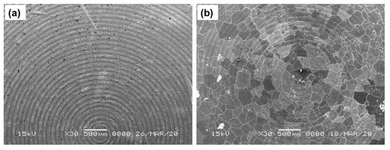
Figure 4.
SEM images of (a) the Li/rGO-S/LiBH4 system and (b) the cycled Li/rGO-S/LiBH4 system (42 cycles).
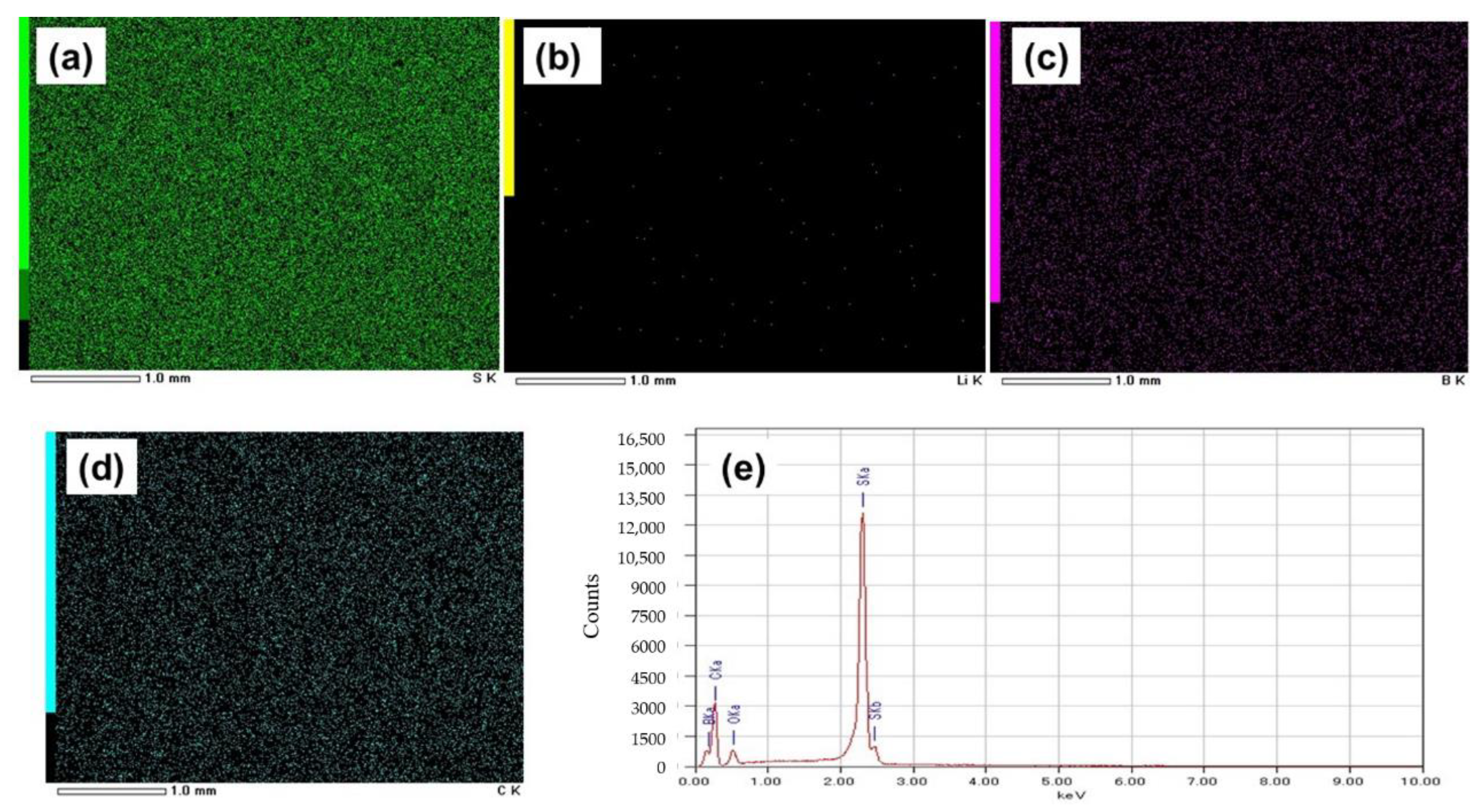
EDS images of the rGO-S composite system (Figure 5a–d) also show the uniform distribution of S, C, and B, having mapping percentages of 70.8%, 17.4%, and 6.5%, respectively (Figure 5e).The SEM image of the same composite electrode without cycling is shown in Figure 4a.From the mapping percentage of the composites, it can be seen that the percentage of carbon in the cathode of the rGO-S system is more when compared to the GO-S cathode system, which may be due to more homogenous mixing of the carbon content that might have played an important role in cycling, as it increased the storage capacity of the electrode.
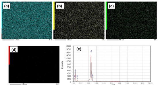
Figure 5.
EDS images of the electrode with rGO-S, showing elements: (a) Sulfur, (b) Carbon, (c) Boron, and (d) Lithium. (e) Mapping graph of the electrode with rGO-S.
Figure 6a,b shows the Galvanostatic charge–discharge profiles of two GO-S composite electrodes with 1%GO-99%S and 10%GO-90%S as active materials, which were performed in the potential range 0.2 V to 4 V at a C-rate of 0.1 C-rate and temperature 120 °C. The capacities shown here are calculated with respect to sulfur content. It is clear that the first discharge cycle of 1%GO-99%S composite delivered a capacity of 1100 mAh/g, which is lower than the theoretical capacity. Conversely, during the charging cycle, it showed a capacity of 1700 mAh/g. This must be due to the simultaneous thermochemical reaction between S and LiBH4 (present as a component in the electrode layer), as suggested in our previous works on M2S3 (M = Bi and Sb) [28,29,30,31]. Actually, during the initial heating process, sulfur partially reacted with LiBH4 (present as a component in the electrode layer) and formed Li2S thermo chemically. Then, during the discharge cycle, the remaining sulfur further reacted with Li-ions (coming from Li-foil at the anode side) electrochemically and converted into Li2S. This is the reason why the initial capacity was observed lower than the theoretical capacity. When it comes to the charging cycle, Li2S starts releasing Li-ions and forms S again. However, this freshly formed S reacts with LiBH4 (present as a component in the electrode layer) thermo chemically again and is converted into Li2S. At this time, the charging process is also going on, so the thermo chemically formed Li2S keeps releasing Li-ions. These simultaneous reactions of S–LiBH4 (thermo chemical) and the Li2S to S conversion (electrochemical charging) continue until the consumption of LiBH4. During the first charging cycle, the cell delivers a capacity more than the theoretical (1675mAh/g) capacity during charging, which might be due to the reaction between sulfur with solid electrolyte LiBH4 (present as a component in the electrode layer) acting as a Li source. The capacity in the first charging cycle was observed higher than the corresponding discharge cycle. A similar behavior was also observed for the other composite (Figure 6b).The first cycle suggests a coulombic efficiency (CE) ~65% for the 1%GO-99%S composite, whereas the cell that has GO10%S90%composite material showed ~84% coulombic efficiency. It can be seen that CE is less, which resembles the parasitic side reaction occurring between S and LiBH4 and irregular Li-ion movements as a result of the shapes and values of the cell voltages’ plateau changing dramatically in subsequent cycles. The discharge reaction of the cell was confirmed by comparing the XRD profile before and after the discharge cycle (Figure S6), where the peaks corresponding to sulfur are found in the as-prepared cell. In addition to sulfur peaks, small peaks corresponding to the Li2S phase are also observed, which confirms our hypothesis of a reaction between S and LiBH4 during the initial heating. These peaks corresponding to Li2S becoming stronger after discharging for both the composites, and all the peaks corresponding to sulfur phase disappear.
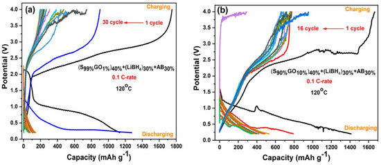
Figure 6.
Galvanostatic charge–discharge profiles of (a) the S99%GO1%electrode and (b) the S90%GO10%electrode.
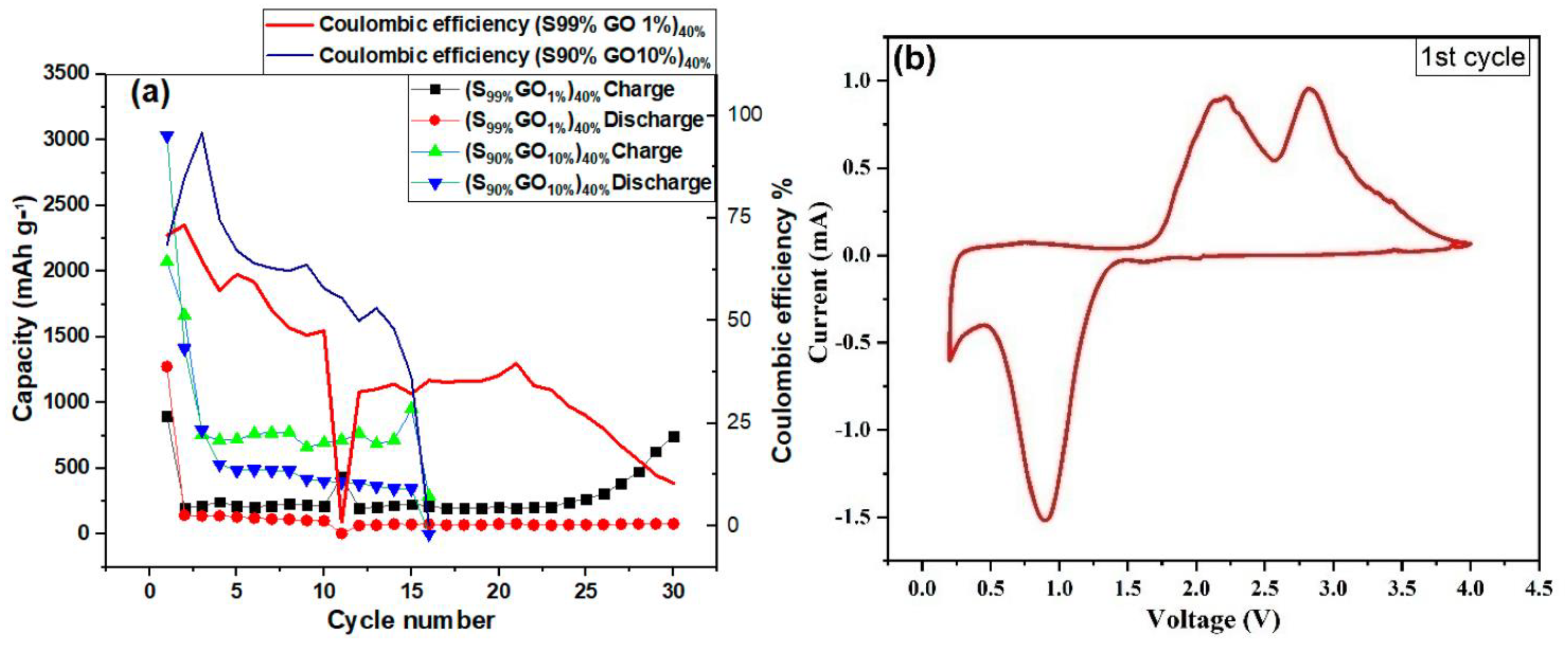
Figure 7a shows the cycling performance of the Li-S cell investigated at a 0.1 C-rate for 30 cycles with a cut-off voltage between 0.2 V and 4.0 V. The reduction in discharge capacity was observed for both composites. The cell with the 1%GO-99%S composite showed a lower initial capacity in comparison to the other composite (10%GO-90%S), but it could be stable and could work up to 30 cycles. The cell with 10%GO-90%S composite stopped working after 16 cycles but delivered a higher capacity of around 400 mAh/g. Figure 7b shows the cyclic voltammetry of the full Li/S cell scanned at 0.1 mV/s operated between 0.2 V to 4 V, which confirms the reversibility of the reaction and is used to decide the potential window for charging-discharging cycles. The CV curve shows one oxidation peak during discharge at 0.86 V, which corresponds to S to Li2S conversion. In contrast, the curve during reduction shows two peaks, which is unusual. It can be explained on the basis of a thermochemical reaction that generated two different species of sulfur/Li2S (structurally same, but kinetically different). Thus, the splitting in the CV curve is due to the different kinetics associated with these.
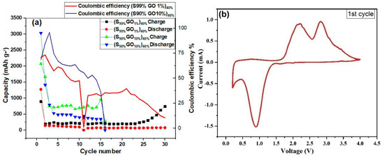
Figure 7.
(a) The cycling performance of the GO-S composite electrode in a potential range2 V to 4 V. (b) Cyclic voltammetry of the GO-S composite electrode scanned at 0.1 mV/s.
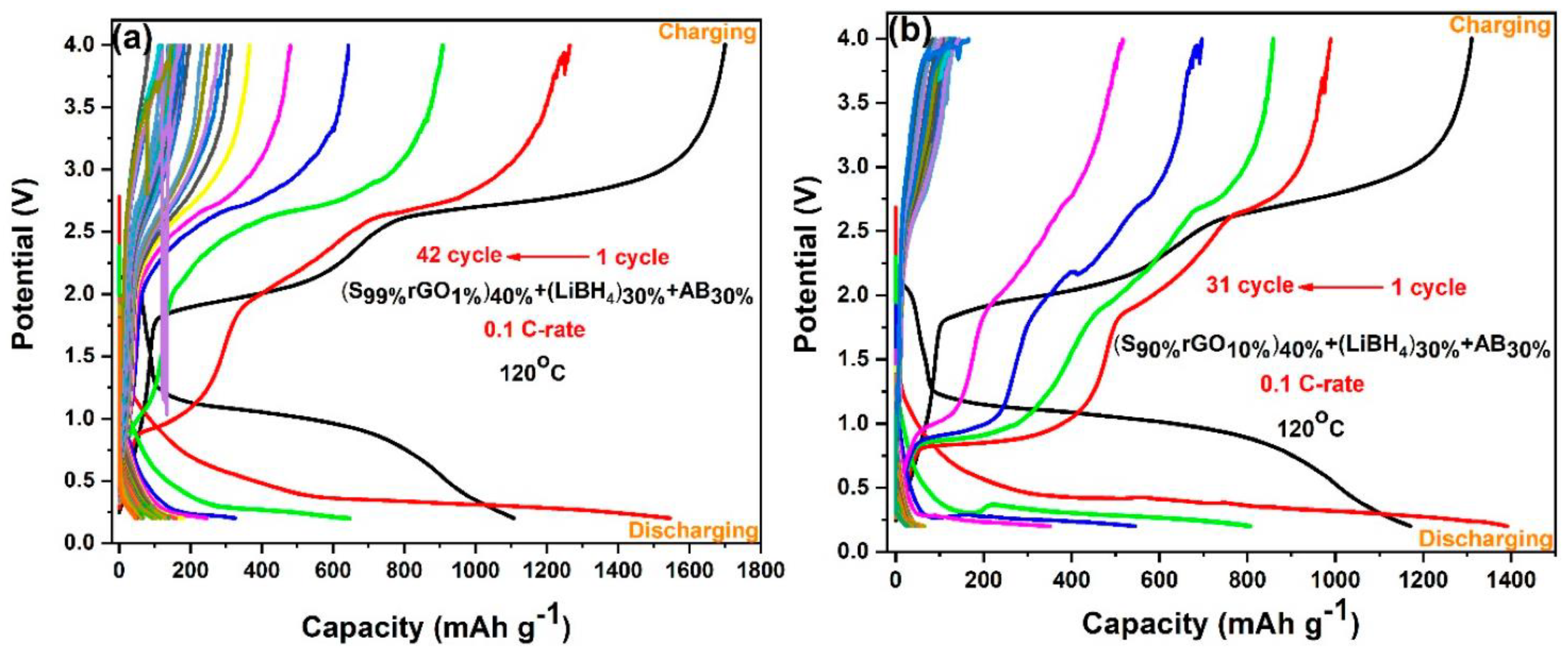
Figure 8a,b shows galvanostatic charge–discharge profiles of Li/S cells containing 1%rGO-99%S and 10%rGO-90%S composite electrodes in the potential range of 0.2 V to 4.0 V at a 0.1 C-rate and 120 °C temperature. The cell with the1%rGO-99%S composite material showed a discharge capacity of 1104 mAh/g (lower than the theoretical capacity) and a charge capacity of 1698 mAh/g (higher than the discharge capacity) in the initial cycle with ~65% coulombic efficiency, which reduced to a constant value around 150 mAh/g after 42 cycles (Figure 8a). The cell with 10%rGO-90%S composite material showed an initial charge capacity of 1309 mAh/g and a discharge capacity of 1165 mAh/g with an ~89% coulombic efficiency. The behavior is quite similar to that of the GO-added samples but with a better capacity. Besides these findings, the second discharge cycle in all the cases showed a higher discharge capacity, which is also associated with the thermochemical reaction between S and LiBH4. In the first cycle, most of the LiBH4 is already exhausted, which leaves more sulfur unreacted and is available to participate in the electrochemical reaction with Li-ions (see above—initially, sulfur reacted with LiBH4 during heating, which reduced the available sulfur content to participate in electrochemical cycling).
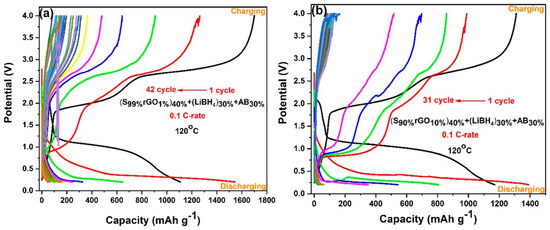
Figure 8.
Galvanostatic charge–discharge profiles of (a) the S99%rGO1%electrode and (b) the S90%rGO10%electrode.
The specific discharge capacity of cells prepared with GO-S and rGO-S composite cathode material showed competitiveness with earlier reported work in which researchers utilized different carbon composite with sulfur by adopting different procedures for composite making and electrolyte. Table 1 shows a list of a few composite materials and their initial performance compared to the results of the present work. However, from Table 1, it can be seen that innovative work of the Li-S battery is, as of yet, incipient and shows that lots of exertion are needed for the commercialization of the battery.

Table 1.
Comparison of the initial discharge capacity of various types of carbon–sulfur composites as cathode materials reported earlier for the Li-S battery of the present study.
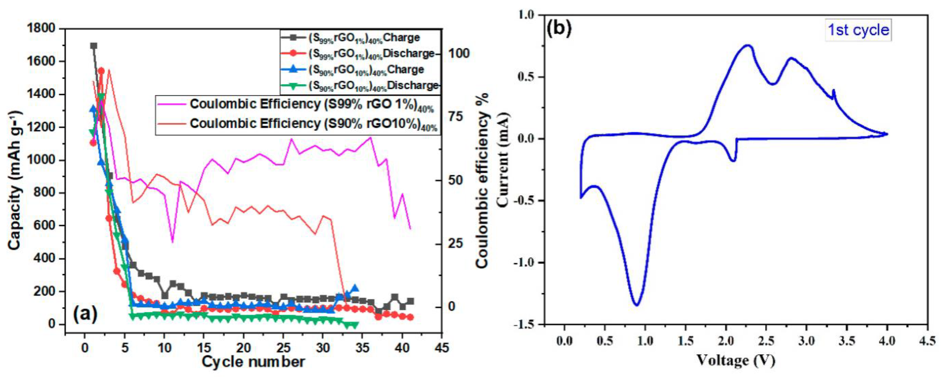
Figure 9a shows the cyclic performance of the Li-S coin cell containing the rGO-S composite electrodes within a potential range of 0.2 V to 4.0 V at a 0.1 C-rate and 120 °C. It has been observed that the cycling and stability of composite having 1%rGO-99%S is better than that of composite having 10%rGO-90%S. It is also noted here that the addition of both GO and rGO is helpful to obtain better stability in comparison to pure sulfur (Figure S7), where the battery works only for two cycles.

Figure 9.
(a) Cycling performance of the rGO-S composite electrode in a potential range 0.2 V to 4 V. (b) Cyclic voltammetry of the rGO-S composite electrode scanned at 0.1 mV/s.
Figure 9b shows consistent CV curves of the rGO-S cathode material used and examined at 0.1 mV/s starting from an open-circuit voltage of 4.0 V to 0.2 V against Li/Li+. Sulfur-reducing CV peaks at ~3.33 V, ~2.81 V, and ~2.27 V can be seen in the reduction scan, which is very similar to that of the GO-containing composites. In the anodic scan from 0.2 V to 4.0 V, two oxidative peaks at ~0.88 V and a smaller peak at ~2.08 V can be seen and connected to the oxidation of PS to S. The appearance of two peaks affirms the overlapping of peaks.
4. Conclusions
All-solid-state Li-S batteries using two different composites of sulfur with GO and rGO were prepared, and their electrochemical performance was investigated. The mechanism of electrochemical charging/discharging is proposed herein by bringing several experiments together. This work suggests a successful implementation of sulfur in all-solid-state batteries using LiBH4 as a solid electrolyte. However, it is observed that sulfur also reacts with LiBH4 thermochemically, which negatively impacts the stability. It is important to examine the performance at lower temperatures (<80 °C) to avoid the thermochemical reaction between sulfur and LiBH4. This can be achieved by using a LiBH4 composite with high conductivity at low temperatures. Since the addition of graphene-modulated additives provided a better path for electron movements, it significantly enhanced the performance of the all-solid-state batteries studied in this work in comparison to pure S, as the sulfur cell without additives did not work for more than two cycles. From the results, it is concluded that the cycling ability and capacity are better with a cathode composite material with rGO (42 cycles) compared to GO (30 cycles) and pristine sulfur (two cycles). The treated composites have shown a great ion transport network with an expanded surface area due to the addition of GO and rGO, which counter the volume expansion of the material during charge and discharge. The results provide insight into a new composite material for enhancing the performance of the Li-S battery.
Supplementary Materials
The following are available online at https://www.mdpi.com/article/10.3390/en14217362/s1, Figure S1: XRD plot of the as-prepared S-LiBH4-AB composite electrode, Figure S2. XRD plot of the (S99%-GO1%)-LiBH4-AB composite electrode, Figure S3. XRD plot of the (S90%-GO10%)-LiBH4-AB composite electrode, Figure S4. XRD plot of the (S99%-rGO1%)-LiBH4-AB composite electrode, Figure S5. XRD plot of the (S90%-rGO10%)-LiBH4-AB composite electrode, Figure S6. XRD plot of cells before and after discharge, Figure S7. Charge-–discharge profile of the S-LiBH4-AB composite electrode without any additive (GO or rGO).
Author Contributions
Conceptualization, B.T. and A.J.; methodology, A.J. and M.K.G.; validation, A.J.; formal analysis, T.P. and R.S.; investigation, T.P. and R.S.; resources, T.I.; data curation, T.P. and B.T.; writing—T.P.; writing—review and editing, B.T. and A.J.; supervision, A.J. and B.T.; All authors have read and agreed to the published version of the manuscript.
Funding
This work is financially supported by the research grant from SERB-DST under ECR scheme (Grant No. ECR/000655/2017) and DBT star scheme (BT/HRD/023/11/2019), Govt. of India, New Delhi.
Data Availability Statement
Data is available with authors and it may be provided on proper request with valid reasons.
Acknowledgments
Authors would like to thank Tomoyuki Ichikawa for his technical help.
Conflicts of Interest
The authors declare no conflict of interest.
References
- Zhao, Y.; Zhang, Y.; Bakenova, Z.; Bakenov, Z. Carbon/sulfur composite cathodes for flexible lithium/sulfur batteries: Status and prospects. Front. Energy Res. 2015, 3, 1–6. [Google Scholar] [CrossRef] [Green Version]
- Ismail, A.M.; Mohammed, M.I.; Fouad, S.S. Optical and structural properties of polyvinylidene fluoride (PVDF)/reduced graphene oxide (RGO) nanocomposites. J. Mol. Struct. 2018, 1170, 51–59. [Google Scholar] [CrossRef]
- Scrosati, B.; Garche, J. Lithium batteries: Status, prospects and future. J. Power Sources 2010, 195, 2419–2430. [Google Scholar] [CrossRef]
- Whittingham, M.S. Lithium Batteries and Cathode Materials. Chem. Rev. 2004, 104, 4271–4301. [Google Scholar] [CrossRef]
- Hassoun, J.; Scrosati, B. Moving to a solid-state configuration: A valid approach to making Li-S batteries viable for practical applications. Adv. Mater. 2010, 22, 5198–5201. [Google Scholar] [CrossRef] [PubMed]
- Cheon, S.E.; Ko, K.S.; Cho, J.H.; Kim, S.W.; Chin, E.Y.; Kim, H.T. Facile preparation and electrochemical properties of carbon-enfolded sulfur particles for Li-S battery application. J. Electrochem. Soc. A 2003, 150, 796–799. [Google Scholar] [CrossRef]
- Ji, L.; Rao, M.; Aloni, S.; Wang, L.; Cairns, E.J.; Zhang, Y. Porous carbon nanofiber-sulfur composite electrodes for lithium/sulfur cells. Energy Environ. Sci. 2011, 4, 5053–5059. [Google Scholar] [CrossRef]
- Wang, H.; Yang, Y.; Liang, Y.; Robinson, J.T.; Li, Y.; Jackson, A.; Cui, Y.; Dai, H. Graphene-Wrapped Sulfur Particles as a Rechargeable LithiumSulfur Battery Cathode Material with High Capacity and Cycling Stability. Nano Lett. 2011, 11, 2644–2647. [Google Scholar] [CrossRef] [Green Version]
- Wei, S.; Zhang, H.; Huang, Y.; Wang, W.; Xia, Y.; Yu, Z. Pig bone derived hierarchical porous carbon and its enhanced cycling performance of lithium-sulfur batteries. Energy Environ. Sci. 2011, 4, 736–740. [Google Scholar] [CrossRef]
- Sun, H.; Xu, G.L.; Xu, Y.F.; Sun, S.G.; Zhang, X.; Qiu, Y.; Yang, S. Composite of sulfur impregnated in porous hollow carbon spheres as the cathode of Li-S batteries with high performance. Nano Res. 2012, 5, 726–738. [Google Scholar] [CrossRef] [Green Version]
- Liang, C.; Dudney, N.J.; Howe, J.Y. Hierarchically Structured Sulfur/Carbon Nanocomposite Material for High-Energy Lithium Battery. Chem. Mater. 2009, 21, 4724–4730. [Google Scholar] [CrossRef]
- Jung, D.S.; Hwang, T.H.; Lee, J.H.; Koo, H.Y.; Shakoor, R.A.; Kahraman, R.; Jo, Y.N.; Park, M.S.; Choi, J.W. Hierarchical Porous Carbon by Ultrasonic Spray Pyrolysis Yields Stable Cycling in Lithium–Sulfur Battery. Nano Lett. 2014, 14, 4418–4425. [Google Scholar] [CrossRef]
- Dash, R.; Chmiola, J.; Yushin, G.; Gogotsi, Y.; Laudisio, G.; Singer, J.; Fischer, J.; Kucheyev, S. Titanium Carbide Derived Nanoporous Carbon for Energy-Related Applications. Carbon 2006, 44, 2489–2497. [Google Scholar] [CrossRef] [Green Version]
- Li, Q.; Zhou, C.; Ji, Z.; Han, B.; Feng, L.; Wu, J. High-performance lithium/sulfur batteries by decorating CMK-3/S cathodes with DNA. J. Mater. Chem. A 2015, 3, 7241–7247. [Google Scholar] [CrossRef]
- Kim, H.; Lim, H.D.; Kim, J.; Kang, K. Graphene for advanced Li/S and Li/air batteries. J. Mater. Chem. A 2014, 2, 33–47. [Google Scholar] [CrossRef]
- Patodia, T.; Sharma, K.B.; Dixit, S.; Katyayan, S.; Agarwal, G.; Jain, S.K.; Saini, C.L.; Tripathi, B. Physico-Chemical Analysis of GO-S and rGO-S Composites as Electrodes for Flexible Li-S Battery. Adv. Sci. Eng. Med. 2021, 12, 1080–1083. [Google Scholar] [CrossRef]
- Cao, Y.; Li, X.; Aksay, I.A.; Lemmon, J.; Nie, Z.; Yang, Z.; Liu, J. Sandwich-type functionalized graphene sheet-sulfur nanocomposite for rechargeable lithium batteries. Phys. Chem. Chem. Phys. 2011, 13, 7660–7665. [Google Scholar] [CrossRef] [PubMed]
- Ji, X.; Nazar, L.F. Advances in Li-S batteries. J. Mater. Chem. 2010, 20, 9821–9826. [Google Scholar] [CrossRef]
- Tripathi, B.; Martinez, M.L.V.; Katiyar, R.K.; Sharma, K.B.; Ram, S.K. Scalable Study on Nanostructured Carbon-Sulfur Composite Electrodes for High Energy Lithium Sulfur (Li-S) Battery. ECS Trans. 2017, 77, 47–57. [Google Scholar] [CrossRef]
- Yu, P.; Xiao, Z.C.; Wang, Q.Y.; Pei, J.K.; Niu, Y.H.; Bao, R.Y.; Wang, Y.; Yang, M.B.; Yang, W. Advanced Graphene@Sulfurcomposites via an in-situ reduction and wrapping strategy for high energy density lithium-sulfur batteries. Carbon 2019, 150, 224–232. [Google Scholar] [CrossRef]
- Hsieh, Y.Y.; Zhang, L.; DeArmond, D.; Kanakaraj, S.N.; Adusei, P.K.; Alvarez, N.T.; Fang, Y.; Daum, J.; Shanov, V. Integrated graphene-sulfur cathode and separator with plasma enhancement for Li-S batteries. Carbon 2018, 139, 1093–1103. [Google Scholar] [CrossRef]
- Zhang, Y.; Zhao, Y.; Yermukhambetova, A.; Bakenov, Z.; Chen, P. Ternary sulfur/polyacrylonitrile/Mg0.6Ni0.4O composite cathodes for high performance lithium/sulfur batteries. J. Mater. Chem. A 2013, 1, 295–301. [Google Scholar] [CrossRef] [Green Version]
- Kolosnitsyn, V.; Karaseva, E. Lithium-Sulfur Batteries: Problems and Solutions. Russ. J. Electrochem. 2008, 44, 506–509. [Google Scholar] [CrossRef]
- Jayaprakash, N.; Shen, J.; Moganty, S.S.; Corona, A.; Archer, L.A. Porous Hollow Carbon-Sulfur Composites for High-Power Lithium-Sulfur Batteries. Chem. Int. Ed. 2011, 50, 5904–5908. [Google Scholar] [CrossRef] [PubMed]
- Zhen, H.; Bo, T.L.; Jian, W.; An, C.-S.; Bin, X.; Chao, Z.J. Synthesis and characterization of a sulfur/TiO2 composite for Li-S battery. J. Phys. Chem. C 2018, 122, 8769–8779. [Google Scholar]
- Singh, R.; Kumari, P.; Rathore, R.K.; Shinzato, K.; Ichikawa, T.; Jain, A.; Kumar, M. LiBH4 as solid electrolyte for Li-ion batteries with Bi2Te3 nanostructured anode. Int. J. Hydrogen Energy 2018, 43, 21709–21714. [Google Scholar] [CrossRef]
- William, S.H.; Richard, O.E. Preparation of Graphitic Oxide. J. Am. Chem. Soc. 1958, 80, 1339. [Google Scholar]
- Sveinbjornsson, S.; Christiansen, A.S.; Viskinde, R.; Norby, P.; Vegge, T. The LiBH4-LiI Solid Solution as an Electrolyte in an All-Solid-State Battery. J. Electrochem. Soc. A 2014, 161, 1432–1439. [Google Scholar] [CrossRef]
- Nagao, M.; Imade, Y.; Narisawa, H.; Kobayashi, T. All-solid-state Li-S batteries with mesoporous electrode and thio-LISICON solid electrolyte. J. Power Sources 2013, 222, 237–242. [Google Scholar] [CrossRef]
- Kumari, P.; Awasthi, K.; Agarwal, S.; Ichikawa, T.; Kumar, M.; Jain, A. Flower-like Bi2S3 nanostructures as highly efficient anodes for all-solid-state lithium-ion batteries. RSC Adv. 2019, 9, 29549–29555. [Google Scholar] [CrossRef] [Green Version]
- Kumari, P.; Singh, R.; Awasthi, K.; Ichikawa, T.; Kumar, M.; Jain, A. Highly stable nanostructured Bi2Se3 anode material for all solid-state lithium-ion batteries. J. Alloys Compd. 2020, 838, 155403. [Google Scholar] [CrossRef]
- Jin, J.; Wen, Z.; Ma, G.; Lu, Y.; Cui, Y.; Wu, M.; Liang, X.; Wu, X. Flexible self-supporting graphene-sulfur paper for lithium sulfur batteries. RSC Adv. 2013, 3, 2558–2560. [Google Scholar] [CrossRef]
- Evers, S.; Nazar, L.F. Graphene-enveloped sulfur in a one pot reaction: A cathode with good coulombic efficiency and high practical sulfur content. Chem. Commun. 2012, 48, 1233–1235. [Google Scholar] [CrossRef] [PubMed]
- Zhang, F.F.; Zhang, X.B.; Dong, Y.H.; Wang, L.M. Facile and effective synthesis of reduced graphene oxide encapsulated sulfur via oil/water system for high performance lithium sulfur cells. J. Mater. Chem. 2012, 22, 11452–11454. [Google Scholar] [CrossRef]
- Wang, Y.X.; Huang, L.; Sun, L.C.; Xie, S.Y.; Xu, G.L.; Chen, S.R.; Xu, Y.F.; Li, J.T.; Chou, S.L.; Dou, S.X.; et al. Facile synthesis of a interleaved expanded graphite-embedded sulphur nanocomposite as cathode of Li-S batteries with excellent lithium storage performance. J. Mater. Chem. 2012, 22, 4744–4750. [Google Scholar] [CrossRef] [Green Version]
- Ying, K.; Tian, R.; Zhou, J.; Li, H.; Dugnani, R.; Lu, Y.; Duan, H.; Guo, Y.; Liu, H. A three dimensional sulfur/reduced graphene oxide with embedded carbon nanotubes composite as a binder-free, free-standing cathode for lithium-sulfur batteries. RSC Adv. 2017, 7, 43483–43490. [Google Scholar] [CrossRef] [Green Version]
- Chen, H.L.; Xiao, Z.J.; Zhang, N.; Xiao, S.Q.; Xia, X.G.; Xi, W.; Wang, Y.C.; Zhou, W.Y.; Xie, S.S. Free-standing, curled and partially reduced graphene oxide network as sulfur host for high-performance lithium-sulfur batteries. Chin. Phys. B 2018, 27, 068101. [Google Scholar] [CrossRef]
- Xi, K.; Kidambi, P.R.; Chen, R.; Gao, C.; Peng, X.; Ducati, C.; Hofmann, S.; Kumar, R.V. Binder free three-dimensional sulphur/few-layer graphene foam cathode with enhanced high-rate capability for rechargeable lithium sulphur batteries. Nanoscale 2014, 6, 5746–5753. [Google Scholar] [CrossRef] [PubMed] [Green Version]
- Lin, T.; Tang, Y.; Wang, Y.; Bi, H.; Liu, Z.; Huang, F.; Xie, X.; Jiang, M. Scotch-tape-like exfoliation of graphite assisted with elemental sulfur and graphene-sulfur composites for high-performance lithium-sulfur batteries. Energy Environ. Sci. 2013, 6, 1283–1290. [Google Scholar] [CrossRef]
- Ding, B.; Yuan, C.; Shen, L.; Xu, G.; Nie, P.; Lai, Q.; Zhang, X. Chemically tailoring the nanostructure of graphene nanosheets to confine sulfur for high-performance lithium-sulfur batteries. J. Mater. Chem. A 2013, 1, 1096–1101. [Google Scholar] [CrossRef]
- Jin, K.; Zhou, X.; Zhang, L.; Xin, X.; Wang, G.; Liu, Z. Sulfur/carbon nanotube composite film as a flexible cathode for lithium-sulfur batteries. J. Phys. Chem. C 2013, 117, 21112–21119. [Google Scholar] [CrossRef]
- Hagen, M.; Dörfler, S.; Althues, H.; Tübke, J.; Hoffmann, M.J.; Kaskel, S.; Pinkwart, K. Lithium-sulphur batteries—Binder free carbon nanotubes electrode examined with various electrolytes. J. Power Sources 2012, 213, 239–248. [Google Scholar] [CrossRef]
- Patodia, T.; Sharma, K.B.; Dixit, S.; Katyayan, S.; Agarwal, G.; Jain, A.; Jain, S.K.; Tripathi, B. Carbon nanotube-sulfur nanocomposite electrodes for high energy-foldable lithium sulfur battery. Mater. Today Proc. 2019, 42, 1638–1641. [Google Scholar] [CrossRef]
- Unemoto, A.; Yasaku, S.; Nogami, G.; Tazawa, M.; Taniguchi, M.; Matsuo, M.; Ikeshoji, T.; Orimo, S.I. Development of bulk-type all-solid-state lithium-sulfur battery using LiBH4 electrolyte. Appl. Phys. Lett. 2014, 105, 083901. [Google Scholar] [CrossRef]
- López-Aranguren, P.; Berti, N.; Dao, A.H.; Zhang, J.; Cuevas, F.; Latroche, M.; Jordy, C. An all-solid-state metal hydride—Sulfur lithium-ion battery. J. Power Sources 2017, 357, 56–60. [Google Scholar] [CrossRef]


Publisher’s Note: MDPI stays neutral with regard to jurisdictional claims in published maps and institutional affiliations. |
© 2021 by the authors. Licensee MDPI, Basel, Switzerland. This article is an open access article distributed under the terms and conditions of the Creative Commons Attribution (CC BY) license (https://creativecommons.org/licenses/by/4.0/).