Article

An Experimental Study of a Thermally Activated Ceiling Containing Phase Change Material for Different Cooling Load Profiles

by
Joanna Sinacka
* and
Edward Szczechowiak
Institute of Environmental Engineering and Building Installations, Poznan University of Technology, Pl. M. Sklodowskiej-Curie 5, 60-965 Poznan, Poland
*
Author to whom correspondence should be addressed.
Energies 2021, 14(21), 7363; https://doi.org/10.3390/en14217363
Submission received: 15 October 2021 / Revised: 30 October 2021 / Accepted: 1 November 2021 / Published: 5 November 2021
(This article belongs to the Section D1: Advanced Energy Materials)

Abstract

:
Increasing peak power demand implies the increasing significance of energy storage. Technologies that efficiently store heat and cold are also important for increasing the share of renewables and improving the efficiency of heating, ventilation, and air conditioning (HVAC) systems. The present experimental study investigated the dynamic behavior of a room with suspended thermally activated ceiling panels filled with a material containing 60% paraffin. The purpose of the study was to determine the specific cooling power and the total energy supplied to the phase change material (PCM) during regeneration. Convective heat flux density, radiant heat flux density, and the heat transfer coefficient (convective, radiant) at the ceiling surface were calculated. Analysis shows that shifting system activation to use lower temperatures during the night maintains thermal comfort.

1. Introduction

The need to reduce energy consumption contributes to the development of energy-efficient and near-zero-energy buildings. Consequently, the overarching goal of HVAC systems is to provide the lowest possible energy consumption [1,2] for maintaining thermal comfort in a building [3]. Thermally activated ceilings can achieve high energy efficiency by reducing transmission losses and supply temperature during cooling. The applied outer skin of the thermally activated panels [4] and their design [5,6] are important.
A phase change material (PCM) stores energy, allowing transfer of the activation of the ceiling to a period of lower temperature during the day and reducing CO2 production by using low-temperature renewable energy sources [7,8]. This was noted by Glück (1999) [9], who conducted numerical experimental studies and proposed computational algorithms for various radiant heating and cooling systems. He proposed heat transfer coefficients and equations to calculate the specific cooling and heating power.
There are three main groups of phase change materials: organic, inorganic (e.g., salt hydrates with a melting point 18.5 °C: KF·4H2O), and eutectic [10,11]. Organic phase change materials are preferred in energy storage systems due to their melting and solidification behavior, low supercooling, fewer vapor pressure changes, easy availability, and non-toxicity [10]. Organic phase change materials are divided into paraffin and non-paraffin organics: fatty acids (CH3(CH2)2nCOOH), alcohols, glycols, and esters (e.g., butyl stearate: CH3(CH2)16COO(CH2)3CH3 with a melting range of 18–23 °C) [11,12].
A well-known solution that uses heat capacity is the ferroconcrete thermally activated building systems (TABS), which were studied by the Swiss research group: Gwerder et al. (2007) [13], Renggli et al. (2007) [14], Gwerder et al. (2008, 2009) [15,16], and Tӧdtli et al. (2009) [17,18], among others. The authors conducted experimental studies and developed models and simulation programs for TABS. The results of their work include the development of a modular control strategy. TABS were also analyzed by Pałaszyńska et al. (2017) [19], Lacarte and Fan (2018) [20], Michalak (2021) [21].
Radiant ceilings filled with PCM serve only to dissipate sensible heat and are, therefore, designed in conjunction with mechanical ventilation to ensure high air quality in the building. The mechanical ventilation system ensures that fresh and dehumidified air is supplied to the room during the summer, preventing condensation on the surface of the radiant ceiling [22]. It can also support the water-based cooling system by supplying outdoor air at night [23].
Koschenz and Lehmann (2004) [24], as one of the first research teams, tested a thermally activated core inserted into a mixture of PCMC (paraffin encapsulated in microcapsules) and gypsum under dynamic conditions. They used aluminum fins to increase heat conduction in the module. In order to determine the thermophysical properties of the system and the parameters that should characterize the PCMC, they developed a one-dimensional numerical model, which was validated by laboratory tests of a prototype (surface of prototype: 0.25 m2). Their analysis showed that a 5-cm-thick layer of microencapsulated PCMC (25% by weight) and gypsum can maintain a comfortable temperature in standard office buildings.
Boiting and Hollenbeck, in a series of articles (2013) [25,26,27], presented calculation procedures and investigation results of a suspended cooling ceiling into which aluminum modules with inorganic PCM (SP21E from Rubitherm) were introduced over a thermally activated core. The measurements were carried out under static conditions according to EN 14240 [28]. In their conclusions, they pointed out the necessity of carrying out a dynamic thermal study in order to know more precisely the influence of the PCM.
Measurements in the unsteady state were undertaken by a German research group from the Bavarian Center for Applied Energy Research (ZAE Bayern) in Würzburg [29,30,31,32]. They analyzed two types of thermally activated panels interacting with aluminum modules filled with salt hydrate, which were either above or below the thermally activated core. Each one was filled with a layer of graphite to intensify heat conduction. They conducted studies in an experimental chamber and office spaces. On the basis of the measurements conducted in the office rooms, they noticed that due to the relatively high phase transition temperature of the material used (22–24 °C), the passive cooling power of the system was low. In order to increase it, they determined that a material with a lower melting and solidification temperature should be used. At the same time, they pointed out that despite the low cooling power, for a thermally activated ceiling area representing 50% of the floor area and with internal heat gains equal to 46 W/m2, the global temperature did not rise to 27 °C until about 7–9 h after the heat gains were turned on.
Allerhand et al. (2019) [33] carried out simulations in the Transient System Simulation Tool (TRNSYS) that indicated that PCM ceilings and TABS reduce peak power by 30% and cooling energy demand by 14–15% compared to an air-based cooling system.
Bourdakis et al. (2015, 2016) [34,35] indicated that regeneration of phase change material using a water-based system is more efficient than using mechanical ventilation during the night. They noted that the use of free cooling is insufficient to discharge a PCM in a Mediterranean climate, while it allows full regeneration in Nordic countries.
Bogatu et al. (2021) [36] conducted a study of a thermally activated panel filled with paraffin whose phase transformation occurs in the temperature range 21–25 °C. This is the first study of cooling radiant panels where the phase change material is in direct contact with a thermally activated core. The authors assessed that this is a promising solution, so it is necessary to carry out measurements of performance under real conditions and energy demand for cooling and heating.
Systems with large heat capacity require appropriate adjustment to the cooling load of the room, which requires study in the unsteady state. The literature analysis indicated that a thermally activated ceiling with PCM infill is a promising solution; however, studies of peak power, energy intake during regeneration, and control methods for adaptive thermal comfort are still lacking. This was the basis for performing experimental studies under dynamic conditions for different user profiles and mass flow of water.
Panels containing PCM are experimentally investigated in this paper. The experiments include the unsteady heat exchange in a room with thermally activated ceiling panels filled with a material containing 60% paraffin. The purpose of the analyzed solution is maintaining a comfortable temperature corresponding to the clothing level and activity of occupants and shifting system activation to use lower temperature at night.
The purpose of the study was to determine the momentary specific cooling power depending on the supply water temperature (Tin), the return water temperature of the cooling ceiling (Tout), the water mass flow during regeneration ( m . ), and the total energy supplied to the cooling ceiling during regeneration of the phase change material. Convective heat flux density, radiant heat flux density, and the heat transfer coefficient (convective, radiant) at the ceiling surface were calculated.

2. Materials and Methods

In the analyzed case, there was unsteady heat transfer (the temperature field varies with time), and its intensity was dependent on the ambient temperature. Momentary radiant heat flux density ( q r ) was defined as in Equation (1):
  q r = C 0 · φ ε 1 2 · ( T P 4 T S 4 ) ,                                 [ W / m 2 ]
where
  • C0—Stefan–Boltzmann constant, C0 = 5.67∙ 10−8 W/(m2 ∙ K4);
  • TP—temperature of the non-activated surfaces, [K];
  • TS—surface temperature of activated panels, [K]; and
  • φ ε 1 2 —emissivity sensitive view factor [37,38]:
φ ε 1 2 = 1 1 ε 1 ε 1 + 1 φ 1 2 + A 1 A 2 · 1 ε 2 ε 2   . [ ]
where
  • ε1, ε2—emissivity of the emitting surface and emissivity of the heat absorbing surface (for building materials: ε1, ε2 = 0.9–0.95), [-];
  • A 1 ,   A 2 —field of the emitting surface and the heat absorbing surface, [m2]; and
  • φ 1 2 —view factor [-].
Whereas momentary convective heat flux density ( q c ) was calculated as follows [39,40]:
q c = α c · ( t i t s ) ,                                 [ W / m 2 ]
where
  • αc—convective heat transfer coefficient, [W/m2 K];
  • ti—air temperature in room, [°C]; and
  • ts—surface temperature of thermally activated panels, [°C].
The convective heat transfer coefficient between the radiant ceiling and the test chamber ( α c ) was determined with Equation (4) (heating) and (5) (cooling):
  • in a heating mode ( R a ( 10 5 ;   10 10 ) ):
α c = Nu · λ a L = 0.27 · ( Gr · P r ) 1 4 · λ a L                                 [ W m 2 K ]
  • in a cooling mode ( R a ( 8 · 10 6 ;   1.5 · 10 9 ) ):
α c = Nu · λ a L = 0.15 · ( Gr · Pr ) 1 3 · λ a L                           [ W m 2 K ]
where
  • L —characteristic dimension of radiant ceiling panel, [m];
  • λ a —thermal conductivity of air, [W/(m·K)];
  • Nu—Nusselt number, [-];
  • Ra —Rayleigh number, [-];
  • Pr—Prandtl number, Pr = ν · ρ · c p λ p [-];
  • Gr—Grashof number, Gr = β · g · ρ 2 · | t s t i | · L 3 μ 2 [-];
  • β —thermal expansion coefficient, [m/s2];
  • g—gravitational acceleration, [m/s2];
  • ρ —density of air, [kg/m3];
  • ts − ti—temperature difference between thermally activated surface and air, [K]; and
  • μ —dynamic viscosity of air, [kg/(ms)].
Ceiling cooling power [41]:
q c = m . w · c w · Δ T w A                           [ W / m 2 ]
where
  • m . w —water mass flow rate, [kg/s];
  • Δ T w —difference between supply and return water temperature, [K];
  • c w —specific heat capacity, [J/(kg∙K)]; and
  • A —area of thermally activated surface, [m].
Thermal activation of ceiling ( Q w ) was performed at night (from “start” to “stop”) and the energy intake during regeneration (water side) was calculated as follows:
Q w = start stop q c dt                             [ Wh / m 2 ]
Characteristic equation of the cooling panel proposed by standard EN 14037 and EN 14240 [28]:
q m = K m · Δ T n                           [ W / m 2 ]
where
  • K m —constant of the characteristic equation, [-];
  • Δ T   —temperature difference of the active surface, [K]; and
  • n —exponent of the characteristic equation of the active surface, [-].

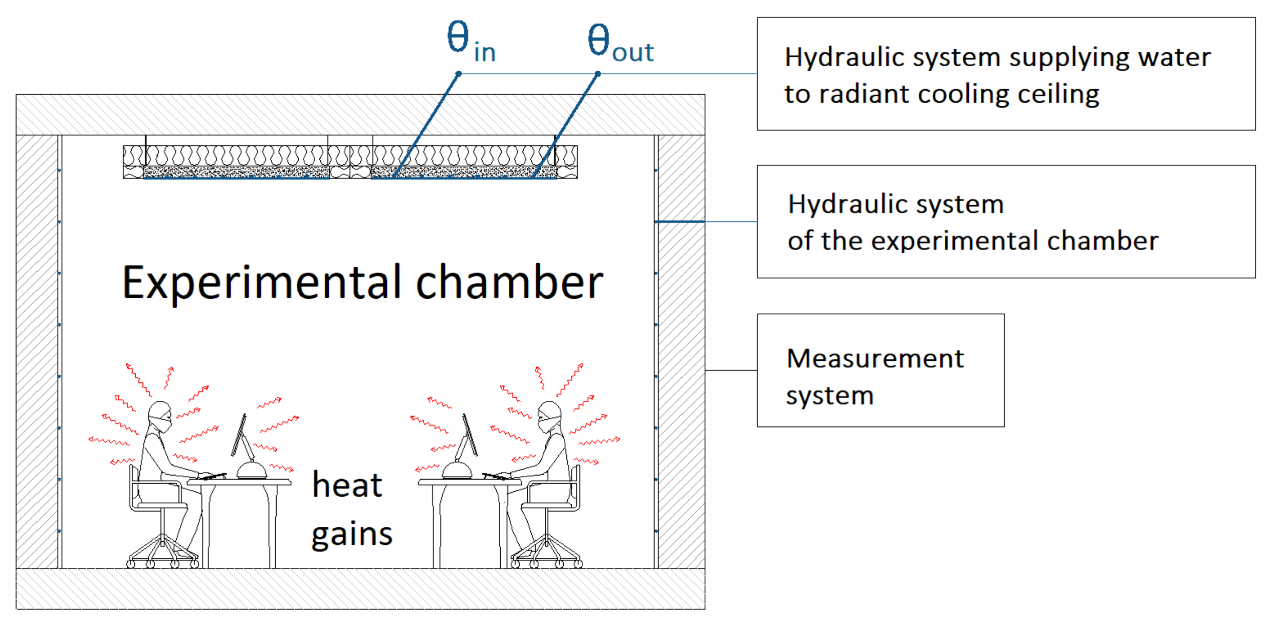
2.1. Experimental Chamber

The tests were conducted in an experimental chamber with dimensions 4.7 × 4.1 × 3.0 m (W × L × H), which provided a stable partition temperature. The walls were insulated with expanded polystyrene (thickness: 0.1 m) with the following parameters: density ρ = 30 kg/m3, specific heat capacity cp = 1.45 kJ/(kg∙K), and thermal conductivity λ = 0.04 W/(m∙K). The test stand consisted of the hydraulic system of the experimental chamber, the hydraulic system supplying water to the radiant cooling ceiling, and the measurement system processing and collecting data; each independent of each other. The structure of the test stand is depicted in Figure 1. A full description of the test stand and the experimental results of the phase change material are detailed in [42].
The 40-mm-high cooling ceiling consisted of two 0.6 × 1.2 m panels and one 0.6 × 2.4 m panel (Figure 2). The thermally activated core was a d-shaped tube arranged in a meander and routed directly above the plane of the steel casing of the panels. Aluminum strips were used to intensify the heat conduction.
The relative humidity of the air in the experimental chamber ranged between 24% and 46%, and the highest air temperature was 30 °C. The dew point temperature for 46% and 30 was 17 °C and was not reached during the experiments (the ceiling surface temperature did not drop below 19 °C). At all times during testing in cooling mode, no air condensation was observed on the panel surface.
The air distribution system dedicated to cooperation with cooling systems with large heat capacity is displacement ventilation, characterized by low air velocity. Therefore, the experimental investigations were carried out for the conditions of natural convection. Air flow in the experimental chamber was inducted solely by the temperature difference. The air velocity did not exceed 0.1 m/s.

2.2. Apparatus and Accuracy

Surface and air temperatures in the chamber, as well as water temperatures were measured using T-type thermocouples (Cu–CuNi, thermocouple wire 2 × 0.5 mm TW Teflon PFA, TW—high heat-resistant and water-resistant thermoplastic material, PFA—perfluoroalkoxy) with a measurement accuracy after calibration no worse than ±0.1 °C. The air temperature was measured in a sheath ensuring elimination of radiation effects. The mass flow of water was measured by the weight method (±0.6%) using a Sartorius laboratory scale with an accuracy of ±0.1 g and a Meteor electronic stopwatch with an accuracy of ±0.01 s. Air temperature and velocity were measured using a draught probe equipped with an omnidirectional thin-film sensor (54T33 sensor) from Dantec Dynamics with an accuracy of ±0.2 K and ±0.02 m/s. Relative humidity was controlled with an air quality meter from Delta Ohm (HD21AB17) with an accuracy of: ±2% (for 10–90% RH) and ±2.5% otherwise. The maintenance of constant water mass flow and constant supply temperature of water with an accuracy of ±0.1 K (simulation of a cold/heat source) was realized using a laboratory thermostat Huber, type K20 (Germany) cooperating with the Pilot ONE controller. All measured parameters (except mass flow rate) were logged continuously.
The heat gain during the measurements in dynamic states was realized using LED bulbs with a total power of 220 W. According to studies by Zhou et al. (2016) [43] and Liu et al. (2017) [44], the heat transferred by high bays by radiation is 42–51% and by convection is 49–58%, as the space fraction equals 1.

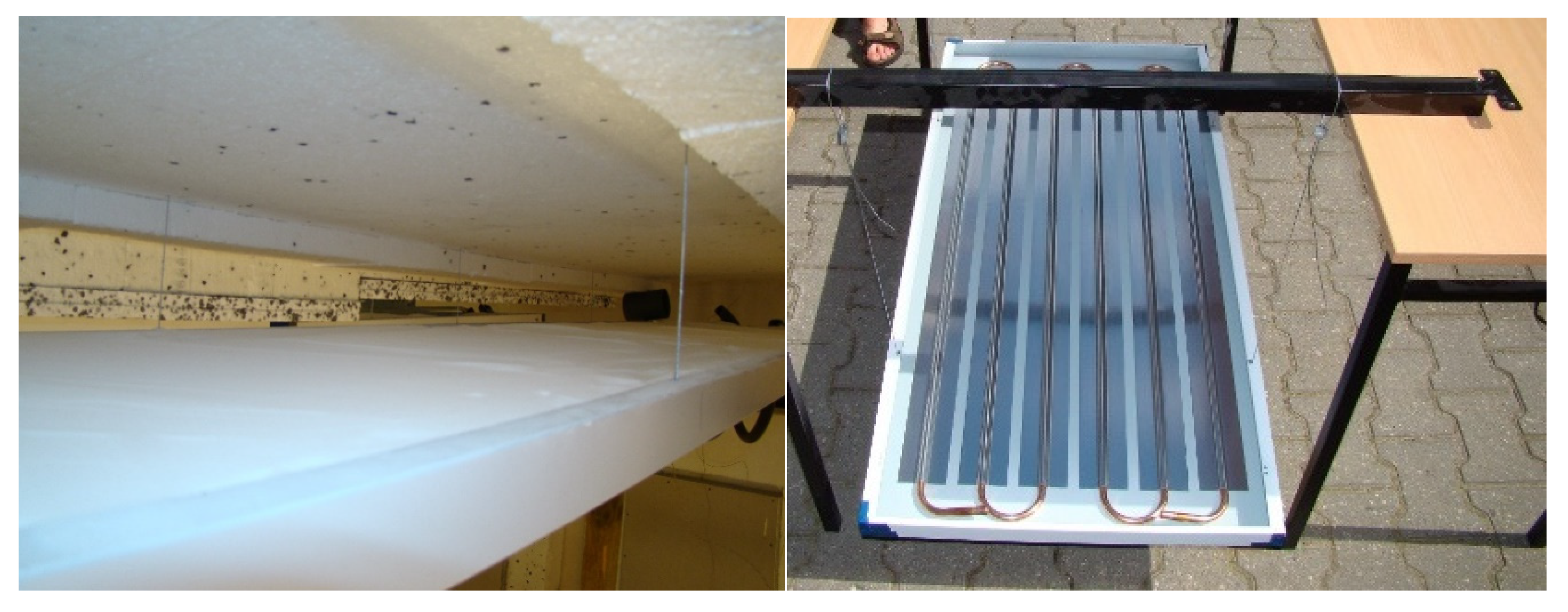
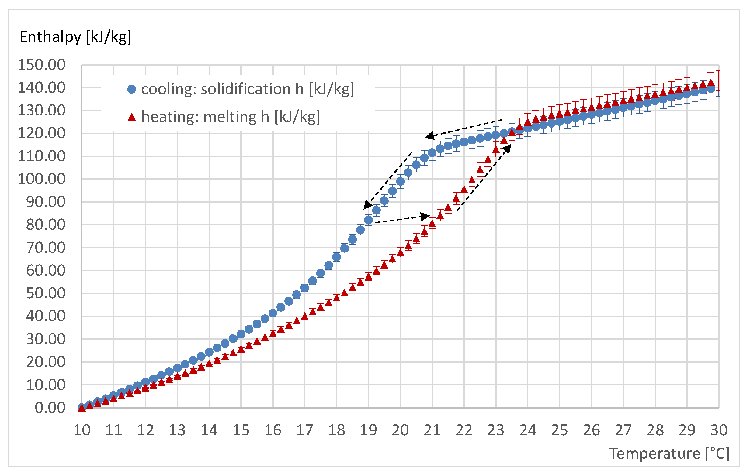
2.3. PCM in Thermally Activated Modules

During the panel filling selection process, special consideration was given to the following: melting and solidification behavior, lack of subcooling, heat conduction, lack of phase separation, non-toxicity, easy accessibility, and stability of thermophysical properties during multiple cyclic phase transitions.
The applied filling of the thermally activated panels was silica powder into which paraffin constituting 60% of the mixture was introduced (by impregnation). It was characterized by stability and chemical inertness and showed little volume change during phase change. The powder was filled in the entire volume inside the cooling panels mounted in the experimental chamber (Figure 3), and its total mass was 72 kg. The phase change temperature range was adjusted to the operating temperature of the thermally activated ceiling without PCM filling to achieve as large as possible a temperature difference between the ceiling surface and the room air temperature during passive cooling, while providing thermal comfort and preventing condensation of water vapor from the air in the room. In the temperature range of 18–25 °C, a 5 cm layer has the same thermal capacity as a 16 cm reinforced concrete ceiling [42]. Partial enthalpy of PCM in modules is presented in Figure 4.

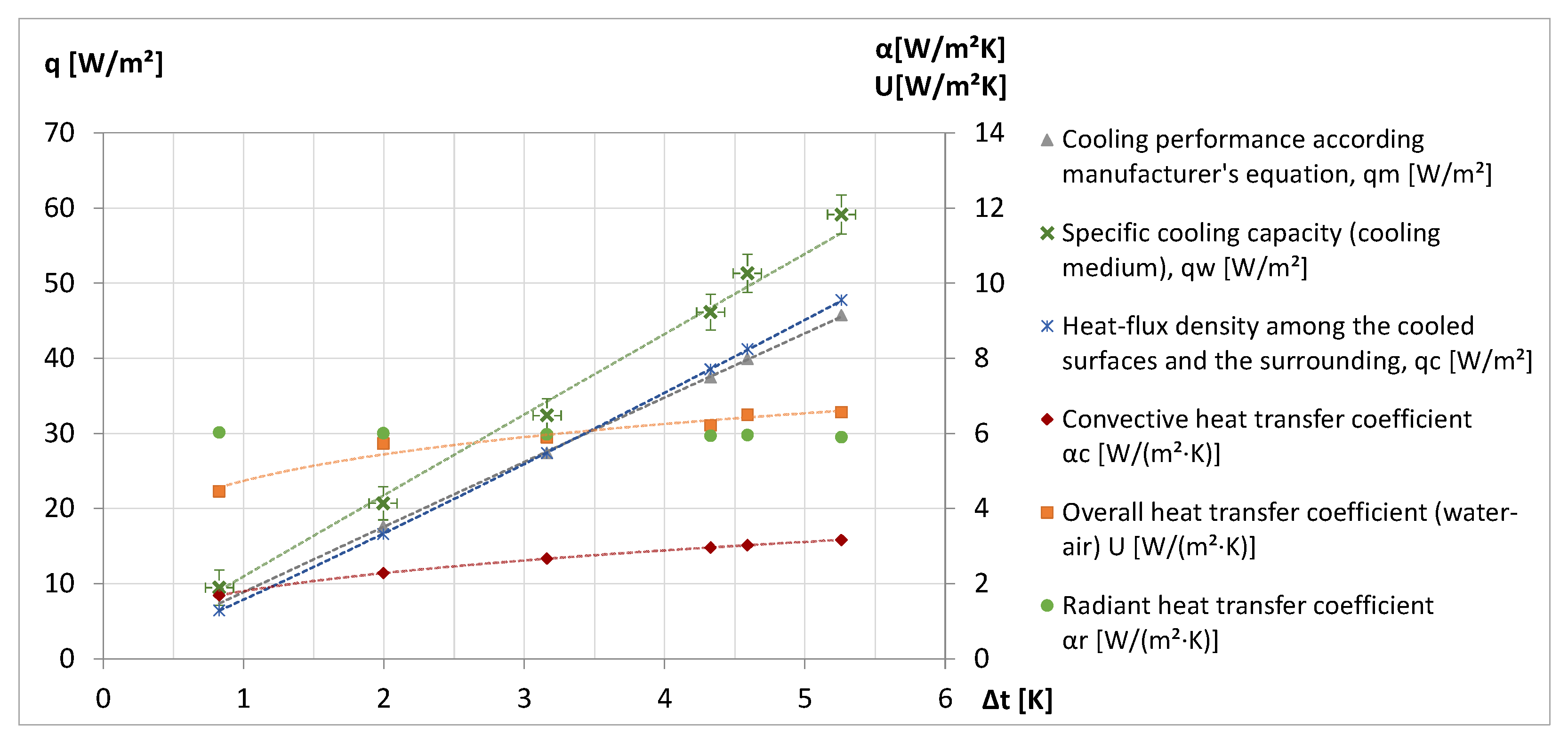
2.4. Cooling Ceiling Modules—Steady State

Steady-state tests included cooling modes of the thermally activated panel without PCM. The room temperature was maintained at 29.5 °C (±0.5 K). The purpose was to determine the operating parameters. Figure 5 shows the specific cooling power, heat transfer coefficients at the panel surface, and the overall heat transfer coefficient (U) between the cooling medium (water) and the air. The specific cooling power resulting from the difference in water temperature (qw), the cooling power resulting from the difference in temperature between the ceiling surface and ambient air using Nusselt number (qc), and the characteristic equation of the cooling panel developed by the manufacturer (qm) were calculated.
Table 1 presents the heat transfer coefficients as function of temperature difference between a thermally activated surface and air (convection αc, Δ T c ) or non-activated surfaces (radiation αr, Δ T r ), the specific cooling power as a function of the difference in ambient temperature and average surface temperature of the thermally activated ceiling ( Δ T a ), and the overall heat transfer coefficient (U) between the cooling medium (water) and the air in room as a function of the difference in average water temperature and ambient temperature ( T w a ).
The convective heat transfer coefficient (α) for the thermally activated ceiling calculated from the steady state results was in the range 1.7 ÷ 3.2 W/(m2 K), and the overall heat transfer coefficient (water–air, U) was 4.5 ÷ 6.5 W/(m2 K). The specific cooling capacity ( q w ) was higher than the heat-flux density among the cooled surface and the surrounding region ( q c ) because of heat losses between water and air. The results obtained for panels without PCM were similar to those presented by Koca and Gürsel and Koca et al. (2017) [45,46].

3. Results and Discussion

Experimental investigations of the cooling ceiling were carried out to determine the dynamic responses of the surface temperature of the radiant ceiling, the air temperature in the experimental chamber, the temperature of the phase change material filling the thermally activated panels, and the return water temperature. These factors depended on the users’ operating profile, the amount of cooling load (heat gains), the mass flow of the water, the inlet water temperature, and the initial room temperature (air and non-activated surface). To control the conditions in the chamber, the relative humidity, air velocity, and radiant temperature (control parameters responsible for the feeling of thermal comfort) were measured. Based on the experimental results, the momentary specific cooling power depending on the supply water temperature (Tin), the return water temperature of the cooling ceiling (Tout), the water mass flow during regeneration ( m . ), and the total energy supplied to the cooling ceiling during the regeneration of the phase change material were calculated. Using the convection–radiation heat transfer equations (Equations (1)–(5)), the heat flux density of the thermally activated ceiling as well as the momentary heat transfer coefficient at the ceiling surface were calculated. The main sources of errors in the experiments were accuracy of instruments, time constant of sensors, and process (for dynamic conditions) as well as limitations of human ability or carelessness (estimation error for mass flow of water measured by weight method).
Figure 6, Figure 7, Figure 8, Figure 9, Figure 10 and Figure 11 show the results of experimental investigations in unsteady states in a room with PCM-filled chilled ceilings for three cooling load profiles. The user profile analyzed was characteristic of an educational room with 10, 15, or 30 min breaks every 1.5 h, and an office space with an 8 h workday (no lunch break) or a 9 h workday with a 1 h lunch break between the fourth and fifth hour of work. Table 2 is a description of the analyzed variants.
The regeneration time of the ceiling depended on the cooling load profile in the room: the shortest for an 8 h office work mode, the longest for an educational room. Temporary cooling power (qc) was referred to 1 m2 of thermally activated ceiling. The tests were carried out while maintaining the temperature of the experimental chamber partitions within the range of 23–23.5 °C.
Analysis of the data shown in Figure 6, Figure 7, Figure 8, Figure 9, Figure 10 and Figure 11 shows that the average PCM ceiling surface temperature (Ts) in each 24 h cycle was lower than the average room air temperature (Ta); in the period of regeneration of PCM, Ts was higher than the water temperature (Tin, Tout) whereas in period of occurrence of the cooling load was lower and decreased faster than the air temperature when the heat gains were turned off. This indicates that the phase change material affected stabilizing thermal conditions.
Internal heat sources (220 W) turned on immediately after the cooling water circuit was turned off resulted in a 1–2 K increase in chamber air temperature for each cooling load profile. Approximately two hours after the heat sources were turned on until they were turned off, a slight increase in room temperature was observed. During the intervals between switching on the heat gain simulator (variants III–VI), the temperature difference between the air and the PCM ceiling surface remained constant. This was influenced by the temperature of the chamber partitions and the heat capacity of the system.
The mass flow rate of the water shaped the water temperature difference between the supply and the return. For a mass flux of 20.3 g/s, the temperature difference decreased to 2 K at the end of the regeneration phase, while for 10.4 g/s, it decreased to 3 K. The higher mass flow rate resulted in a slight increase in the difference between the air temperature and the PCM ceiling surface temperature. For the analyzed variants, the lower mass flow rate (10.4 g/s) was sufficient to provide thermal comfort in the room.
The temperature amplitude of the phase change material filling the PCM ceiling during the 24 h cycle for the office room averaged 1.2 K, while for the education room, it was about 2 K. This was influenced by different regeneration times. The longest was set for the cooling load profile of the educational room (10 h, 20 min). Due to the temperature range in which phase change takes place, regeneration time, and lack of additional solutions intensifying thermal conductivity, incomplete solidification was observed in each analyzed daily cycle.
Results (absolute values) were significantly affected by the initial temperature setting of the experimental chamber partitions. This indicates that it is necessary to measure and control the conditions immediately before the hours when users will be present to determine the control strategy of the system in real conditions.
Figure 12 and Figure 13 show the heat transfer coefficients (αk, αr) and heat flux density of the thermally activated ceiling (qk, qr) by introducing discrete steady states for a full test cycle (24 h) and separating the period of regeneration of the phase change material and the period of occurrence of the cooling load. The figures were created based on the results collected for variants Ia–IIIb. The parameters describing the convective heat transfer (qk, αk) were presented depending on the temperature difference between the surface of the ceiling with PCM and the air. Parameters describing radiative heat transfer (qr, αr) were presented as a function of the temperature difference between the PCM ceiling surface and the other thermally non-activated surfaces. The range of the temperature difference shown in the figures corresponds to the operating conditions of the system for the analyzed variants. Higher temperature differences were obtained during the regeneration time.
Table 3 presents the heat transfer coefficient and heat flux density as function of temperature difference between a thermally activated surface and air (convection, Δ T c ) or non-activated surfaces (radiation, Δ T r ).
Figure 12 and Figure 13 and the equations in Table 2 for activation time and work hours are similar, thus confirming the validity of the study and equations used.

4. Conclusions

The present study conducted under dynamic conditions shows that filling a suspended thermally activated ceiling with a phase change material improves the thermal capacity of the module and stabilizes the room temperature. It allows the activation of the ceiling and, thus, causes the peak power to be shifted to a period of lower temperature in the 24 h cycle and provides thermal comfort during the occupied hours of the room, while allowing improved interaction with low-temperature renewable energy sources.
Energy intake during regeneration is strongly related to the room occupancy profile and system operating parameters such as water flow rate, supply water temperature, and time of regeneration. Small differences between the room air temperature and the ceiling surface temperature during occupied hours allow for a high level of self-regulation of the system.
When a ceiling with PCM is activated, the room air temperature and the ceiling surface temperature change. The effect is observed immediately after activation of the circulation pump, which means that the system can quickly change room conditions even during times of excess heat gain (maintained property of panels without PCM filling).
The integration of the thermally activated ceiling with the PCM increases the complexity of the energy audit, the design process, and the control strategy development process, therefore unsteady state analyses are necessary. Due to the influence of the phase change material used, its location, and the construction of the ceiling panels on the thermal properties, it is necessary to perform experimental studies for each new system.
Knowing the design cooling load and the system behavior under dynamic conditions, it is possible to calculate the required heat capacity:
s t a r t s t o p q ˙ g a i n s · Δ t c = s t a r t s t o p q ˙ r + k · A · Δ t c = m · Δ h P F     [ J ]
where
  • q ˙ g a i n s —heat gains, [W];
  • Δ t c —time step (period of occurrence of cooling load), [s];
  • q ˙ r + k —total heat flux density (period of occurrence of cooling load), [W/m2];
  • A —area of thermally activated ceiling, [m2];
  • Δ h P F PCM enthalpy difference for system operation range, [J/kg];
  • m —PCM mass, [kg]; and
  • s t a r t s t o p —period of occurrence of cooling load.
The combination of thermally activated ceiling and compact energy storage (PCM) is a promising and innovative cooling technology to reduce energy consumption. The results indicate that the next step is to work on increasing the thermal performance and intensifying the heat conduction of the panel filling, e.g., through elements made of material with high thermal conductivity (e.g., aluminum, copper) in the form of fins, rods, or strips. The experimental investigations were carried out for the conditions of natural convection. In the next phase, the research should be extended to cooperation with various ventilation systems.
For the solution to become commercial, it is necessary to ensure fire safety, so it is necessary to carry out fire tests of the module, especially the material from which the housing of the panels will be made and to develop a tight construction.

Author Contributions

Conceptualization, J.S. and E.S.; methodology, J.S.; software, J.S.; validation, J.S., and E.S.; formal analysis, J.S.; investigation, J.S.; resources, J.S.; data curation, J.S.; writing—original draft preparation, J.S.; writing—review and editing, E.S.; visualization, J.S.; supervision, E.S.; funding acquisition, E.S. All authors have read and agreed to the published version of the manuscript.

Funding

This research was funded by the Polish Ministry of Science and Higher Education, grant no. 504 101/0713/SBAD/0948, 504 101/0713/SBAD/0910, 504 101/0713/DSPB/0888.

Institutional Review Board Statement

Not applicable.

Informed Consent Statement

Not applicable.

Data Availability Statement

Not applicable.

Conflicts of Interest

The authors declare no conflict of interest.

References

  1. Ratajczak, K.; Szczechowiak, E. The Use of a Heat Pump in a Ventilation Unit as an Economical and Ecological Source of Heat for the Ventilation System of an Indoor Swimming Pool Facility. Energies 2020, 13, 6695. [Google Scholar] [CrossRef]
  2. Sinacka, J.; Ratajczak, K. Analysis of selected input data impact on energy demand in office building—Case study. MATEC Web Conf. 2018, 222, 01015. [Google Scholar] [CrossRef]
  3. Sinacka, J.; Szczechowiak, E. Operational Analysis for Passive House in Aspect of Climate Comfort and Energy Demand. Dist. Heat. Heat. Vent. 2017, 48, 497–504. (In Polish) [Google Scholar]
  4. Amanowicz, Ł.; Wojtkowiak, J. Experimental investigations of thermal performance improvement of aluminum ceiling panel for heating and cooling by covering its surface with paint. In Proceedings of the 10th Conference on Interdisciplinary Problems in Environmental Protection and Engineering EKO-DOK, Zdrój, Poland, 14–16 April 2018; Volume 44. [Google Scholar] [CrossRef]
  5. Wojtkowiak, J.; Amanowicz, T.; Mróz, T. A new type of cooling ceiling panel with corrugated surface—Experimental investigation. Int. J. Energy Res. 2019, 43, 7275–7286. [Google Scholar] [CrossRef]
  6. Wojtkowiak, J.; Amanowicz, T. Effect of surface corrugation on cooling capacity of ceiling panel. Therm. Sci. Eng. Prog. 2020, 19, 100572. [Google Scholar] [CrossRef]
  7. Romaní, J.; de Gracia, A.; Cabeza, L.F. Simulation and control of thermally activated building systems (TABS). Energy Build. 2016, 127, 22–42. [Google Scholar] [CrossRef] [Green Version]
  8. Romaní, J.; Cabeza, L.F.; Pérez, G.; Pisello, A.L.; de Gracia, A. Experimental testing of cooling internal loads with a radiant wall. Renew. Energy 2018, 116, 1–8. [Google Scholar] [CrossRef] [Green Version]
  9. Glück, B. Thermische Bauteilaktivierung—Nutzen von Umweltenergie und Kapillarrohren; C. F. Müller: Heidelberg, Germany, 1999. [Google Scholar]
  10. Sahan, N.; Paksoy, H. Determining influences of SiO2 encapsulation on thermal energy storage properties of different phase change materials. Sol. Energy Mater. Sol. Cells 2017, 159, 1–7. [Google Scholar] [CrossRef]
  11. Sharma, A.; Tyagi, V.V.; Chen, C.R.; Buddhi, D. Review on thermal energy storage with phase change materials and applications. Renew. Sustain. Energy Rev. 2009, 13, 318–345. [Google Scholar] [CrossRef]
  12. Soares, N.; Costa, J.J.; Gaspar, A.R.; Santos, P. Review of passive PCM latent heat thermal energy storage systems towards buildings’ energy efficiency. Energy Build. 2013, 59, 82–103. [Google Scholar] [CrossRef]
  13. Gwerder, M.; Tödtli, J.; Lehmann, B.; Renggli, F.; Dorer, V. Control of Thermally Activated Building Systems. In Proceedings of the 9th REHVA World Congress Clima, WellBeing Indoors, Helsinki, Finland, 10–14 June 2007. [Google Scholar]
  14. Renggli, F.; Gwerder, M.; Tödtli, J.; Lehmann, B.; Dorer, V. Effect of The Hydraulic Piping Topology on Energy Demand and Comfort in Buildings with Tabs. In Proceedings of the 9th REHVA World Congress Clima, WellBeing Indoors, Helsinki, Finlandy, 10–14 June 2007. [Google Scholar]
  15. Gwerder, M.; Lehmann, B.; Tödtli, J.; Dorer, V.; Renggli, F. Control of thermally-activated building systems (TABS). Appl. Energy 2008, 85, 565–581. [Google Scholar] [CrossRef]
  16. Gwerder, M.; Tödtli, J.; Lehmann, B.; Dorer, V.; Güntensperger, W.; Renggli, F. Control of thermally activated building systems (TABS) in intermittent operation with pulse width modulation. Appl. Energy 2009, 86, 1606–1616. [Google Scholar] [CrossRef]
  17. Tödtli, J.; Gwerder, M.; Lehmann, B.; Renggli, F.; Dorer, V. TABS Control: Steuerung und Regelung von Thermoaktiven Bauteilsystemen; FAKTOR Verlag AG: Zürich, Switzerland, 2009. [Google Scholar]
  18. Tödtli, J.; Gwerder, M.; Renggli, F.; Güntensperger, W.; Lehmann, B.; Dorer, V.; Hildebrand, K. Regelung und Steuerung von thermoaktiven Bauteilsystemen (TABS). Bauphysik 2009, 31, 319–325. [Google Scholar] [CrossRef]
  19. Pałaszyńska, K.; Bandurski, K.; Porowski, M. Energy demand and thermal comfort of HVAC systems with thermally activated building systems as a function of user profile. E3S Web Conf. 2017, 22, 00130. [Google Scholar] [CrossRef] [Green Version]
  20. Lacarte, L.M.D.; Fan, J. Modelling of a thermally activated building system (TABS) combined with free-hanging acoustic ceiling units using computational fluid dynamics (CFD). Build. Simul. 2018, 11, 315–324. [Google Scholar] [CrossRef] [Green Version]
  21. Michalak, P. Selected Aspects of Indoor Climate in a Passive Office Building with a Thermally Activated Building System: A Case Study from Poland. Energies 2021, 14, 860. [Google Scholar] [CrossRef]
  22. Sinacka, J.; Szczechowiak, E. Heat Flow Modelling in a Building with Thermally Activated Building Systems. Dist. Heat. Heat. Vent. 2018, 49, 271–278. (In Polish) [Google Scholar]
  23. Pomianowski, M.; Khalegi, F.; Domarkas, G.; Taminskas, J.; Bandurski, K.; Madsen, K.; Gedsø, S.; Lund, R. Experimental investigation of the influence of obstacle in the room on passive night-time cooling using displacement ventilation. In Proceedings of the 9th Nordic Symposium on Building Physics—NSB, Tampere, Finland, 29 May–2 June 2011. [Google Scholar]
  24. Koschenz, M.; Lehmann, B. Development of a thermally activated ceiling panel with PCM for application in lightweight and retrofitted buildings. Energy Build. 2004, 36, 567–578. [Google Scholar] [CrossRef]
  25. Boiting, B.; Hollenbeck, P. PCM-Kühldecken. Teil 1: Grundlagen. HLH Klimatech. 2013, 64, 108–111. [Google Scholar]
  26. Boiting, B.; Hollenbeck, P. PCM-Kühldecken. Teil 2—Berechnungs- und Auslegungsverfahren. HLH Klimatech. 2013, 64, 88–91. [Google Scholar]
  27. Boiting, B.; Hollenbeck, P. PCM-Kühldecken. Teil 3—Neue Ansätze. HLH Klimatech. 2013, 64, 74–76. [Google Scholar]
  28. Anonymous. Ventilation for Buildings—Chilled Ceilings—Testing and Rating; EN 14240; CEN: Brussels, Belgium, 2004. [Google Scholar]
  29. Klinker, F.; Weinläder, H.; Konstantinidou, A.C. Dynamic Thermal Behaviour of Two Newly Developed PCM Cooling Ceiling Prototypes. In Proceedings of the EuroSun 2014, Aix-Les-Bains, France, 16–19 September 2014. [Google Scholar]
  30. Weinläder, H.; Klinker, F.; Yasin, M. PCM cooling ceilings in the Energy Efficiency Center—Regeneration behaviour of two different system designs. Energy Build. 2017, 156, 70–77. [Google Scholar] [CrossRef]
  31. Weinläder, H.; Klinker, F.; Yasin, M. PCM cooling ceilings in the Energy Efficiency Center—Passive cooling potential of two different system designs. Energy Build. 2016, 119, 93–100. [Google Scholar] [CrossRef]
  32. Yasin, M.; Scheidemantel, E.; Klinker, F.; Weinläder, H.; Weismann, S. Generation of a simulation model for chilled PCM ceilings in TRNSYS and validation with real scale building data. J. Build. Eng. 2019, 22, 372–382. [Google Scholar] [CrossRef]
  33. Allerhand, J.Q.; Kazanci, O.B.; Olesen, B.W. Energy and thermal comfort performance evaluation of PCM ceiling panels for cooling a renovated office room. CLIMA 2019, 111, 03020. Available online: https://www.e3s-conferences.org/articles/e3sconf/abs/2019/37/e3sconf_clima2019_03020/e3sconf_clima2019_03020.html (accessed on 1 October 2021).
  34. Bourdakis, E.; Pean, T.Q.; Gennari, L.; Olesen, B.W. Daytime space cooling with phase change material ceiling panels discharged using rooftop photovoltaic/thermal panels and night-time ventilation. Sci. Technol. Built Environ. 2016, 22, 902–910. [Google Scholar] [CrossRef] [Green Version]
  35. Bourdakis, E.; Olesen, B.W.; Grossule, F. Night time cooling by ventilation or night sky radiation combined with in-room radiant cooling panels including phase change materials. In Proceedings of the 36th AIVC Conference, Madrid, Spain, 23–24 September 2015. [Google Scholar]
  36. Bogatu, D.-I.; Kazanci, O.B.; Olesen, B.W. An experimental study of the active cooling performance of a novel radiant ceiling panel containing phase change material (PCM). Energy Build. 2021, 243, 110981. [Google Scholar] [CrossRef]
  37. Cholewa, T.; Anasiewicz, R.; Siuta-Olcha, A.; Skwarczynski, M.A. On the heat transfer coefficients between heated/cooled radiant ceiling and room. Appl. Therm. Eng. 2017, 117, 76–84. [Google Scholar] [CrossRef]
  38. Cholewa, T.; Rosiński, M.; Spik, Z.; Dudzińska, M.R.; Siuta-Olchaa, A. On the heat transfer coefficients between heated/cooled radiant floor and room. Energy Build. 2013, 66, 599–606. [Google Scholar] [CrossRef]
  39. Wojtkowiak, J.; Amanowicz, Ł. Investigation of heating and cooling power of ceiling panel. Dist. Heat. Heat. Vent. 2016, 47, 413–417. (In Polish) [Google Scholar]
  40. Sinacka, J.; Szczechowiak, E.; Żabicka, P. Influence of usage profile on energy needs for heating and cooling in a building with thermally activated building systems. Instal 2019, 10, 34–37. (In Polish) [Google Scholar]
  41. Sinacka, J. Thermal Properties of Heating and Cooling Ceilings Filled with Phase Change Material. Ph.D. Thesis, Poznan University of Technology, Poznan, Poland, 2021. (In Polish). [Google Scholar]
  42. Amanowicz, L. Controlling the Thermal Power of a Wall Heating Panel with Heat Pipes by Changing the Mass Flowrate and Temperature of Supplying Water—Experimental Investigations. Energies 2020, 13, 6547. [Google Scholar] [CrossRef]
  43. Zhou, X.; Lochhead, S.J.; Zhong, Z.; Van Huynh, C. Low Energy LED Lighting Heat Distribution in Buildings; ASHRAE Research Project RP-1681, Final Raport; ASHRAE: Atlanta, GA, USA, 2016; 176p. [Google Scholar]
  44. Liu, R.; Zhou, X.; Lochhead, S.J.; Zhong, Z.; Van Huynh, C.; Maxwell, G.M. Low-energy LED lighting heat gain distribution in buildings, part II: LED luminaire selection and test results. Sci. Technol. Built Environ. 2017, 23, 688–708. [Google Scholar] [CrossRef]
  45. Koca, A.; Gürsel, C. Experimental investigation on the heat transfer coefficients of radiant heating systems: Wall, ceiling and wall-ceiling integration. Energy Build. 2017, 148, 311–326. [Google Scholar] [CrossRef]
  46. Koca, A.; Acikgoz, O.; Cebi, A.; Cetin, G.; Dalkilic, A.S.; Wongwises, S. An experimental investigation devoted to determine heat transfer characteristics in a radiant ceiling heating system. In Heat Mass Transfer; Springer: New York, NY, USA, 2017; pp. 1–13. [Google Scholar]
Figure 1. Structure of the test stand [42].
Energies 14 07363 g001
Figure 2. PCM ceiling test stand [42].
Energies 14 07363 g002
Figure 3. Thermally activated panel containing PCM [42].
Energies 14 07363 g003
Figure 4. Partial enthalpy of PCM in modules [42].
Energies 14 07363 g004
Figure 5. Experimental results for thermally activated ceiling—cooling mode.
Energies 14 07363 g005
Figure 6. Experimental results for variant Ia.
Energies 14 07363 g006
Figure 7. Experimental results for variant Ib.
Energies 14 07363 g007
Figure 8. Experimental results for variant IIa.
Energies 14 07363 g008
Figure 9. Experimental results for variant IIb.
Energies 14 07363 g009
Figure 10. Experimental results for variant IIIa.
Energies 14 07363 g010
Figure 11. Experimental results for variant IIIb.
Energies 14 07363 g011
Figure 12. Quasi-steady-state conditions—activation time and work hours.
Energies 14 07363 g012
Figure 13. Quasi-steady-state conditions—(a) activation time c, (b) work hours.
Energies 14 07363 g013
Table 1. Equations proposed for the calculation of thermal properties.
Thermal Properties of Cooling Ceiling ModulesActivation Time
Cooling performance (according to the manufacturer) [W/m2] q m = 8.8812 · Δ T a 0.9846
(R2 = 0.9998)
Specific cooling capacity [W/m2] q w = 10.967 · Δ T a 0.9893
(R2 = 0.9957)
Heat-flux density [W/m2] q c = 7.8817 · Δ T a 1.0839
(R2 = 1)
Convective heat transfer coefficient [W/(m2 K)] α c = 1.8023 · Δ T c 0.3392
(R2 = 1)
Radiant heat transfer coefficient [W/(m2 K)] α r = 5.9 ÷ 6.0
Overall heat transfer coefficient [W/(m2 K)] U = 3.8769 · Δ T w a 0.246
(R2 = 0.9165)
Table 2. Description of analyzed variants—unsteady state.
VariantUser ProfileTemperature of Water Inlet, Tin [°C] Water   Mass   Flow   Rate ,   m . [ g / s ]
IaOffice (8 h, 220 W)15.520.3
IbOffice (8 h, 220 W)15.510.0
IIaEducational (10:20 h = 6 × 1.5 h and breaks between, 220 W)15.521.0
IIbEducational (10:20 h = 6 × 1.5 h and breaks between, 220 W)15.710.4
IIIaOffice (4 h + 4 h with 1 h break between work hours, 220 W)15.520.4
IIIbOffice (4 h + 4 h with 1 h break between work hours, 220 W)15.510.4
Table 3. Equations proposed for the calculation of heat flux density and heat transfer coefficient.
Activation TimeWork Hours
Convective heat flux density [W/m2] q c = 1.8297 · Δ T c 1.3347
(R2 = 0.9978)
q c = 1.8234 · Δ T c 1.2769
(R2 = 0.9995)
Radiant heat flux density [W/m2] q r = 11.419 · Δ T r 0.9927
(R2 = 1)
q r = 11.379 · Δ T r 1.005
(R2 = 1)
Convective heat transfer coefficient [W/(m2 K)] α c = 1.8297 · Δ T c 0.3347
(R2 = 0.9668)
α c = 1.8234 · Δ T c 0.2769
(R2 = 0.9887)
Radiant heat transfer coefficient [W/(m2 K)] α r = 5.56 ÷ 5.71 α r = 5.5 ÷ 5.71
Publisher’s Note: MDPI stays neutral with regard to jurisdictional claims in published maps and institutional affiliations.

