Article

Designing Virtual Reality Environments through an Authoring System Based on CAD Floor Plans: A Methodology and Case Study Applied to Electric Power Substations for Supervision

by
Camilo de Lellis Barreto Junior
1,*,
Alexandre Cardoso
1,
Edgard Afonso Lamounier Júnior
1,
Paulo Camargos Silva
1 and
Alexandre Carvalho Silva
2
1
Faculty of Electrical Engineering, Federal University of Uberlândia, Uberlândia 38408-902, Brazil
2
Graphics Processing and Natural Interaction Research Group, Goiano Federal Institute, Morrinhos 75650-000, Brazil
*
Author to whom correspondence should be addressed.
Energies 2021, 14(21), 7435; https://doi.org/10.3390/en14217435
Submission received: 24 September 2021 / Revised: 31 October 2021 / Accepted: 4 November 2021 / Published: 8 November 2021

Abstract

:
The adoption of Virtual Reality (RV) technologies in prototype design and process revision has contributed to multiple industry areas. Nonetheless, the development of VR systems for engineering is a complex task, as it involves specialized teams handling low-level code development. Given these problems, the goal of this study is presenting a methodology for designing VR, through an Authoring System based on Computer-Aided Design (CAD). The presented methodology provides an easy integration of electric power substation floor plans and Virtual Reality software (VRS), as well as three-dimensional and symbol modeling conventions. Centralized software architecture was developed, composed of the CAD Editor, input manager and VRS. The methodology was evaluated through a case study applied to the conception (elaboration) of electric power substations (EPS) as part of a Research and Development (R&D) project for training and field assets supervision. The results demonstrated visual precision and high integrity in elaboration of a VR environment from the CAD floor plan. This work also presents a comparative analysis between manual conception and the Authoring System.

1. Introduction

The application of Virtual Reality (VR) techniques has improved many processes in multiple industry areas. For instance, construction industries employ VR technologies in design and processes revision associated with Computer-Aided Design (CAD) [1]. In addition, electric power companies use advanced user interfaces as a complement to conventional diagram management and field asset supervision [2].
VR is an advanced interface for computer applications that allows users to navigate in real time in three-dimensional (3D) environments with multisensory devices for activation or feedback [3]. It also provides a high level of immersion and fidelity in the representation of information [4].
VR is currently one of the most important areas emerging in computer technologies [5]. It is becoming widely employed in training processes, industrial tests [6,7], architecture, engineering [8], education, simulation and in fast prototyping [9]. The studies by [10,11,12,13,14,15,16] use VR applied to training, simulation and supervision of critical systems in the electric power industry as a paradigm for optimizing production processes, maximizing performance of field operators and preventing occupational accidents.
The development of Virtual Reality software (VRS) based on engineering drawings involves complex creation and maintenance processes, as it demands specialized teams for design and implementation of three-dimensional scenarios and graphic interfaces through computer graphics tools [17,18,19,20]. These obstacles are amplified when it comes to large-scale production. Such development needs specialized work, leading to a high implementation cost (financially and in terms of time), which to a certain extent makes the processes of elaborating and updating the Virtual Environments (VE) [21] difficult, and hinders scenario updates.
The VR development process for training and supervision of EPS has similar levels of complexity compared to those described previously. Many VR systems, in the context of electrical engineering, use game engines such as Unity [22], Unreal [23] and Lumberyard [24]. They are tools focused on games where users have deep knowledge and experience. For instance, Moreno et al. [25] presents a training system created with Unity with the support of external software and plugins, such as WorldComposer, Adobe Fuse, SolidWorks and 3Ds Max. As a consequence, these tools can be impracticable for inexperienced users.
An important characteristic for the development of VEs is the automatic integration enters the software of modeling and VR with the modeling and VR software. This process, focused on the final user, facilitates and eliminates the manual work of adjusting CAD models for game engines and also software development. Moreover, the automatic methodology makes it possible to execute maintenance in the VEs without the need to generate new versions of the VR software.
Therefore, the motivation of this work is based on the need for methodologies for the production and updating of EPS VE with remote supervision. Such methodologies use CAD technologies used by electrical system operators.
In the current literature many authors propose integration techniques and methodologies to unify engineering projects and VR as demonstrated by Mattioli et al. [26]. That work presents a semi-automated method of symbol recognition, data extraction and spatial positioning with a scene editor inside the game engine Unity.
Another strategy for integrating engineering drawings was presented by Gebert et al. [27]. It uses a metamodel concept that defines a data structure combining information from 3D models and Product Data Management systems in an integration file. This file can then be used and interpreted by a VR system.
Freeman et al. [28] proposes the use of parametric CAD architecture and incorporation with VR through a Siemens NX [29] software plugin. The plugin extracts data (mesh data, hierarchy, etc.) from the 3D model and serializes. The extracted data are shared with a VRS through a defined network structure.
None of these studies presents a solution for automated integration through authoring tools for VR engineering project replication in VR. In addition, these studies lack design methodologies that facilitate creation and distribution for users with little or no knowledge of computer graphics software. A comparison of related works and the present study is shown in Section 2.
This work research theme addresses CAD artifacts integration problems found in VE elaboration processes. The production of VEs based on manual processes adopted in game engines increases the development schedule time and makes large-scale production unfeasible. Therefore, we propose a VE conception methodology based on CAD floor plans through a centralized and adaptable software architecture. The methodology focuses on electrical power substations (EPS) for real-time field asset supervision.
Therefore, given the scenario of difficulties faced in the process of developing and designing VEs for engineering and the potential application of VR techniques, this research has the goal of presenting the development and assessment of an Authoring System (AS) based on engineering drawings in CAD floor plans.
It aims to describe the methodology for the design and customization of EPS in VR with the possibility of transmitting spatial and functional information during the process of supervising field assets. The following specific objectives are numbered:
  • Propose and design a software architecture of the Authoring System composed of an input management system, CAD floor-plan editor, Virtual Reality software and communication with asset supervision servers;
  • Present the development of a CAD editing system to create and customize floor-plan drawings through the manipulation of symbols and elements stored in a web management system;
  • Propose geometric and symbol modeling conventions to meet the demands of the VR and Authoring systems;
  • Propose a design integration strategy between CAD editing and the Virtual Reality software appropriate data structure and suitable for sharing VE construction information over the Internet;
  • Assess the work through a Case Study using a real EPS, with the aim of analyzing the software architecture, VE design methodology with the CAD Editor, as well as the capability to reuse 3D geometric objects, integration strategy and its reliability regarding the real environment;
  • Show the differences and demonstrate the accuracy of the scenario generated by the Authoring system, regarding the positioning of the assets against the manual design methodology.

2. Related Works

2.1. Description of Related Works

Mattioli et al. [26] proposes the development of a tool to integrate CAD and Unity [22] software. The methodology presented by the authors extracts information from the floor plan and exports it into to the Unity editor, where users can subsequently insert and position the elements. The results showed that the scene built using the conventional methodology took 20 h to complete and with the proposed methodology, it had a time reduction to 6 h.
Gebert et al. [27] proposes the development of a tool that enables the integration of CAD models in VR systems. The authors present an integration methodology using a metamodel concept, which defines a data structure that gathers different information from distributed systems. The authors developed a metamodel file able to contain information from the Product Data Management (PDM), 3D models and CAD as well as simulation data in an Extensible Markup Language (XML) file.
The work, proposed by Freeman et al. [28], presents the development of a VR system that provides the loading of parametric CAD models and allows the manipulation of objects and their attributes. The authors demonstrated the development of a set of integration tools. The results suggest that the created solution allowed the synchronization of parameterized CAD software and the possibility of reviewing mechanical engineering projects with VR. The authors mentioned that users were able to better understand the model geometry and gained more confidence due to the intuitive and attractive characteristics of the proposed tool.
Han et al. [30] proposes the development of an VR and Augmented Reality (AR) tool to perform analysis and revisions of piping arrangements for offshore structures. The system architecture applies CAD technologies used in the pipeline elaboration process. According to the authors, the prototype developed shows that the proposed strategy can be applied in the conversion and integration of CAD software with pipeline 3D models. Consequently, the usage of these models in VR/AR applications should be simplified, as the models produced are not ready to use.
The work by Lorens et al. [31] proposes the development of a methodology for an automated conversion process of CAD models into a format widely used by VR and AR applications, keeping CAD models simulation, animation and kinematics data. Some limitations were highlighted as the lack of CAD and VR compatible file format available. The authors applied tests to assess the benefits of the proposed methodology. They showed that the conversion process can provide a CAD model with animations and kinematics to a VR environment, without the need for complex manual work.
Zawadzki et al. [32] presents an integrated configurable product design process that includes two steps: (i) the configuration of a product variety with customer input and (ii) the preparation of technical documentation. The authors propose the development of a VR tool, integrating the concept of configurable products applied to the customization of an urban bus. It allows users to modify seating arrangements, handrails and other internal aspects of the product. For such a solution, it was chosen to model products in CAD with the generative technology, a model creation strategy with modeling rules and logics that enables to develop a primary model with modifiable components following predefined rules. According to the authors, tests with Virtual Design Studio (VDS) confirm the possibility of integrating CAD models with VR systems using the proposed methodology. The author’s proposed strategy also the time needed to prepare the design and technical documentation.

2.2. Considerations about Related Works

The works of [27,28,30,31,32] present a methodology of integration of three-dimensional CAD models with VR software through an automatic process, except the work of [32], where a semi-automatic process is applied. In [32], parametric modeling is used, and the 3D model is configured by some parameters and is produced automatically. This aspect can be less productive, as the process of adjustment of 3D models is manual.
Automatic integration between modeling and VR software is an important feature in VE creation methodologies. Mainly when the system is destined for less experienced users. In such a way, the methodology allows carrying out maintenance of the scenes of a productive form, excusing the manual stages of the adequacy of CAD models, programming of source code, and the production of a new version of the VR.
EPS are designed, in part, through floor plans and symbols representing real objects. The work of [26] presents a system for semi-automatic generation of VEs for EPS by extracting data from floor plans. The presented results reinforce the effectiveness of the adopted strategy. Hence, the possibility of using floor plans for the production of VR scenarios is justified.
In [27], is presented an integration strategy using metamodel. Its advantage is the ability to define a data structure model where information from multiple sources can be grouped and transformed into an integration file. Additionally, it allows communication standardization between CAD and VR software.
Through the review, it is possible to observe that none of these works provide simultaneously: (i) automatic integration between CAD and VR software; (ii) adaptive centralized software architecture, based on client–server architecture; (iii) management of inputs and data used in VEs and their respective virtual scenarios; (iv) topology of elements in the scenario; and (v) Virtual Environment reconstruction process at runtime in the instances of each VR software. These are important and desirable characteristics to a better understanding of the necessities of an Authoring System of VR for EPS.
As mentioned, the automatic integration process allows the user to perform maintenance on the VEs without complex processes. Therefore, it is possible to separate the development of VEs in CAD software from the use of VRS in tasks regarding control and supervision. This distinction requires the software to be coordinated by an VE manager.
In [27], the authors used a PDM software to manage product information. The system is dedicated to controlling assets for sales. However, the authors do not present a system for managing its elements in VR. An asset manager in projects would enable greater control of the elements used in each VE.
Therefore, adaptive client–server software architecture is important to unify CAD and VRS. This configuration allows multiple instances of CAD and VRS to run simultaneously. Additionally, remote access to the VE manager allows system managers to manage projects, users, and access control.
Equipment such as the Disconnector Switch allows the flow of electrical current from the arrays. This action is carried out by conducting arms displaced from their position by motors. This action is important to be presented to operators through animation to view equipment status, providing an additional level of realism, and can be achieved through hierarchical structures using graphs.
The electrical topology in virtual substations is a fundamental attribute for supervision, training, and simulation. The links between equipment, created by the electrical connections, form a logical system that allows the visualization of the electric current flow and possible interruptions in the system. Thus, when a circuit breaker is deactivated (accidentally or not), it is possible to analyze the chain of events and the flow of electric current in the system. Therefore, the VEs are enriched with visual and textual information about the substation asset status.
All these features provide the necessary elements for the Authoring System and the VR software assets supervision. Through these attributes, it is also possible to create, edit, manage, and use substation VEs.
Thus, the detailed analysis showed that the related works did not address all the mentioned attributes simultaneously. There is also no evidence of methodologies for producing VEs of EPS through floor plans and software architecture, encompassing VR, CAD, and VE management software.

3. Materials and Methods

In this section, the concepts and specifications presents for the approach proposed. Initially, the AS software architecture is presented, along with the details of its components. Finally, the methodology presents the creating and customizing Virtual Environments by manipulating CAD floor plans and their integration with the VRS.

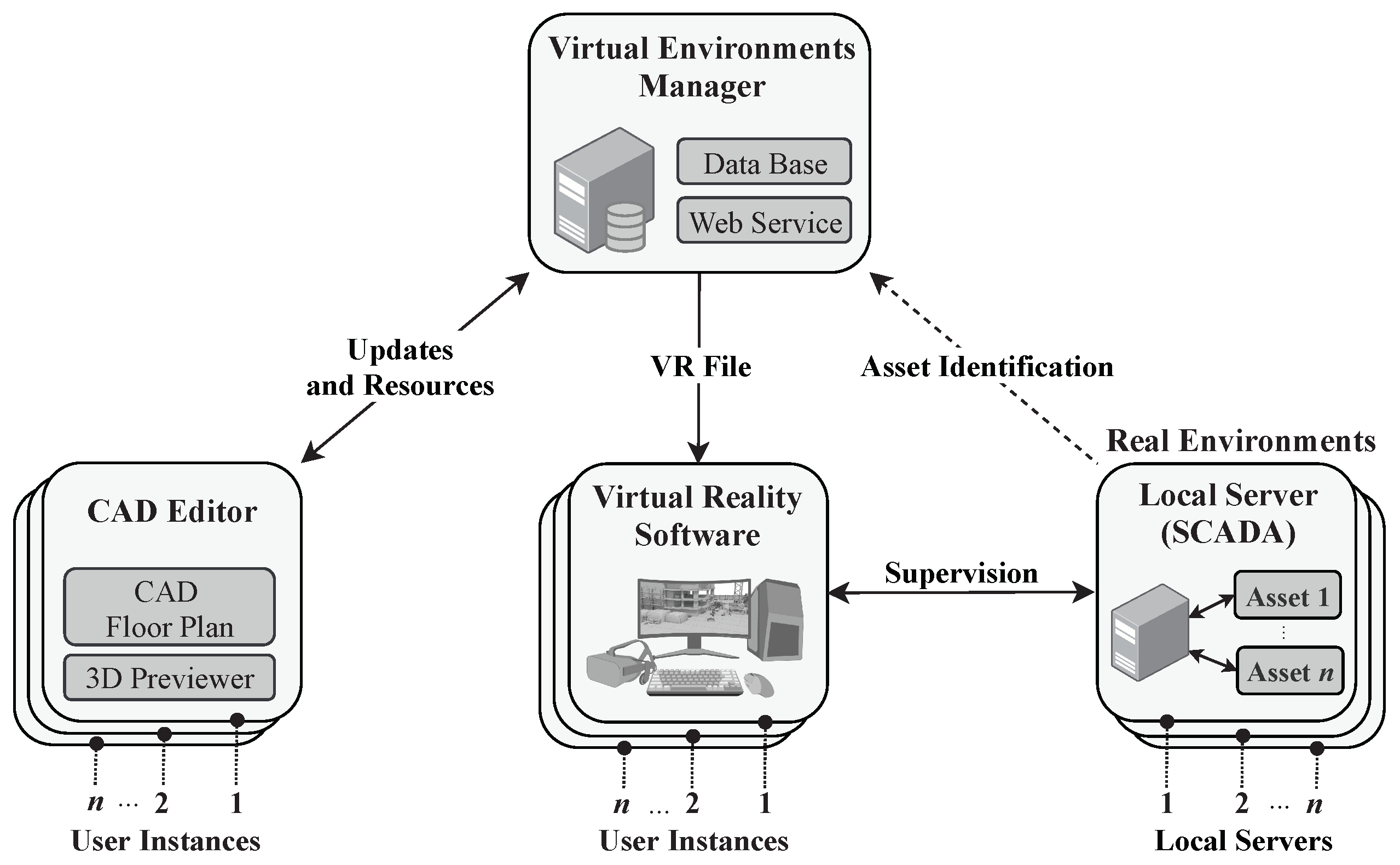
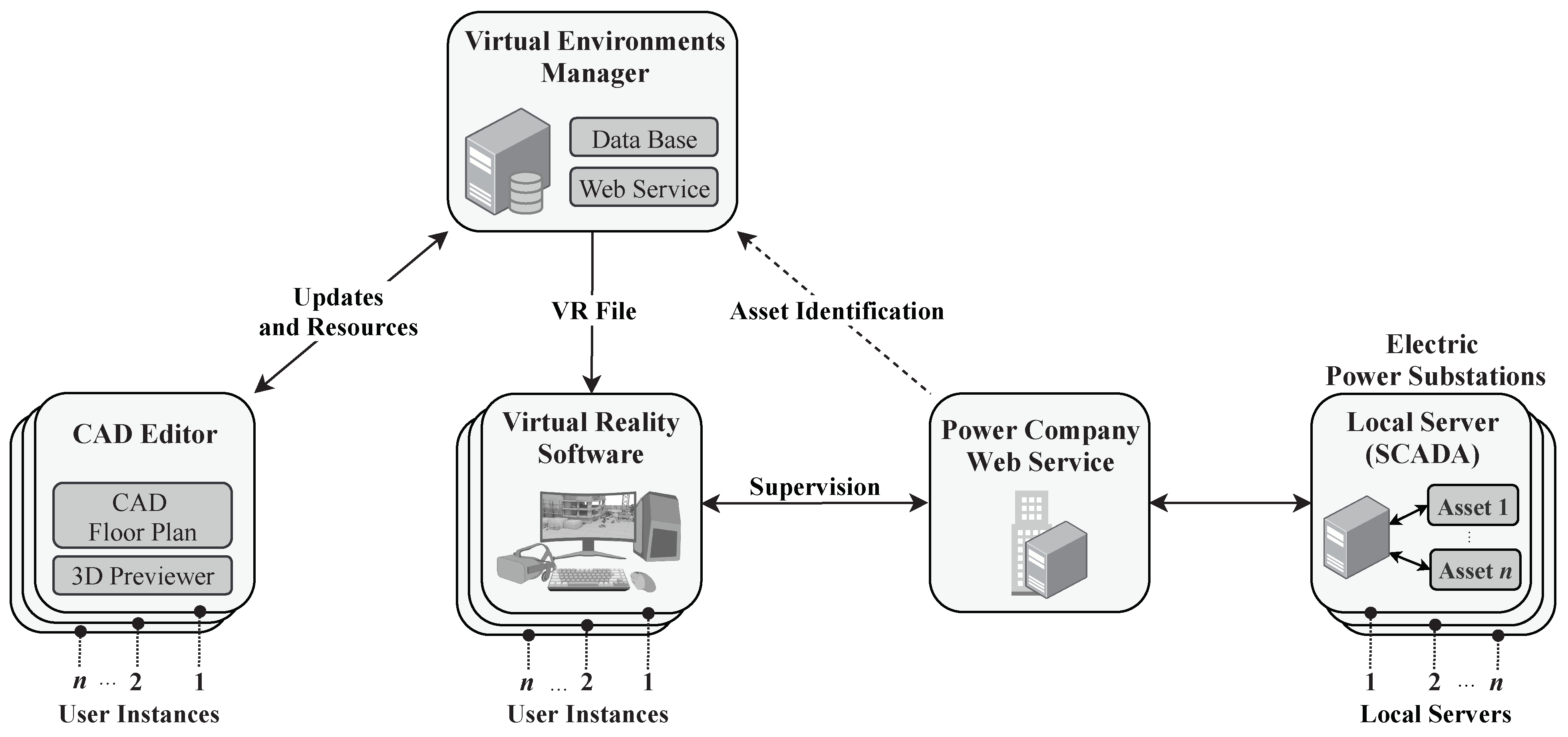
3.1. Architecture of the Authoring System

Figure 1 presents a short introduction for the proposed AS architecture. It is composed of three essential components:
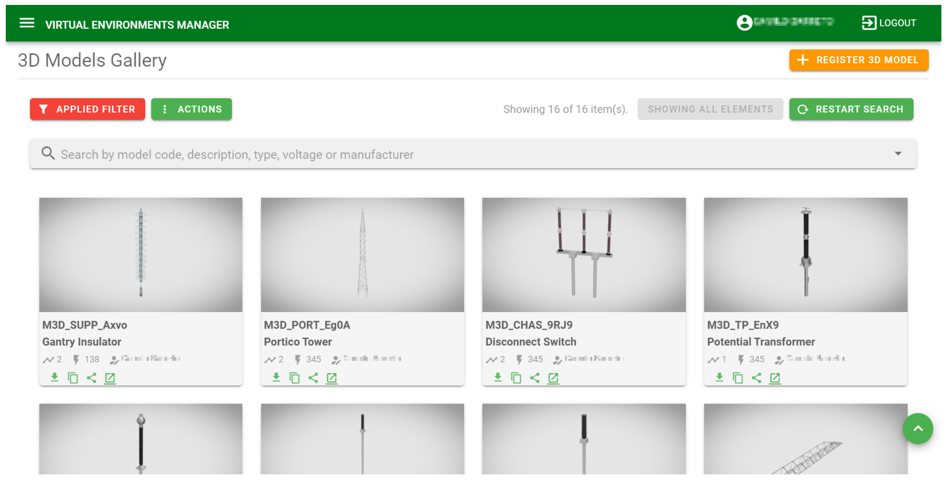
  • Virtual Environment Manager (VEM): server responsible for storing the necessary virtual assets (3D models, CAD symbols, etc.) and manage the information between the CAD Editor and the Virtual Reality software;
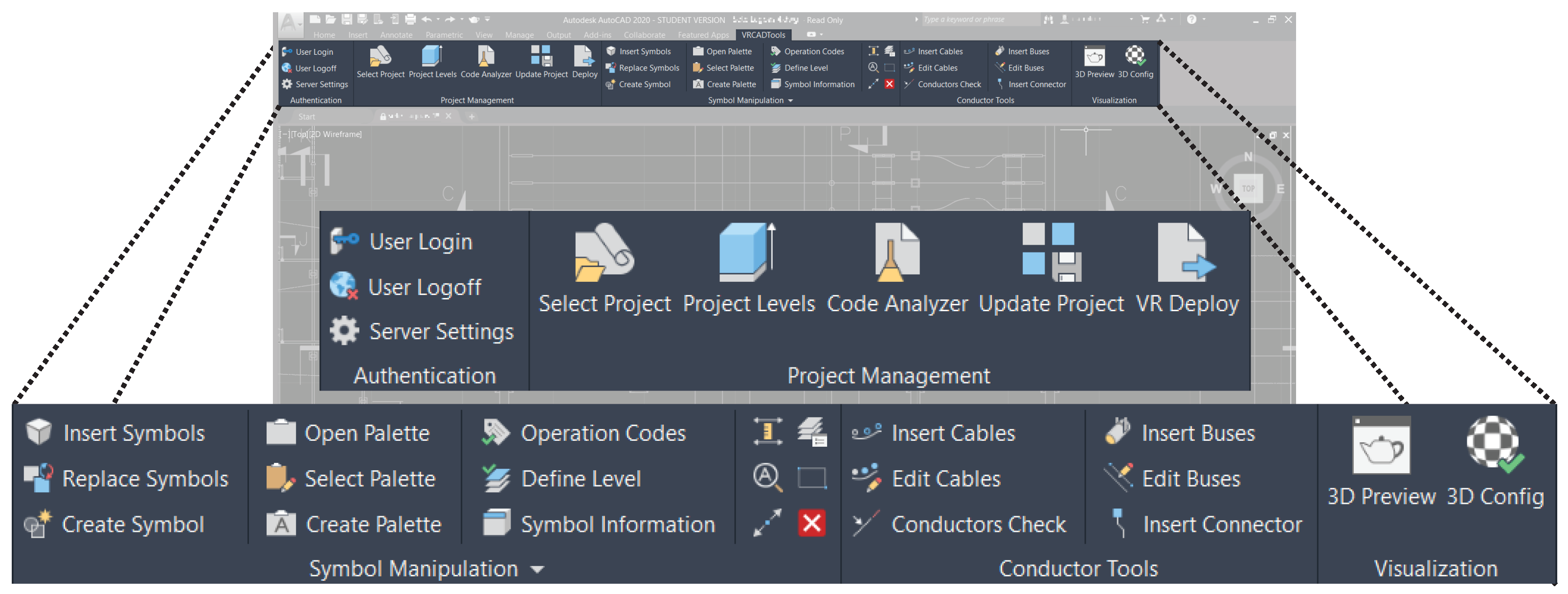
  • CAD Editor (CADE): is the software used for the design and customization of floor plans. It is composed of groups of tools with specific purposes, such as the authentication of the user, project management, symbol manipulation, floor-plan review and VR implementation;
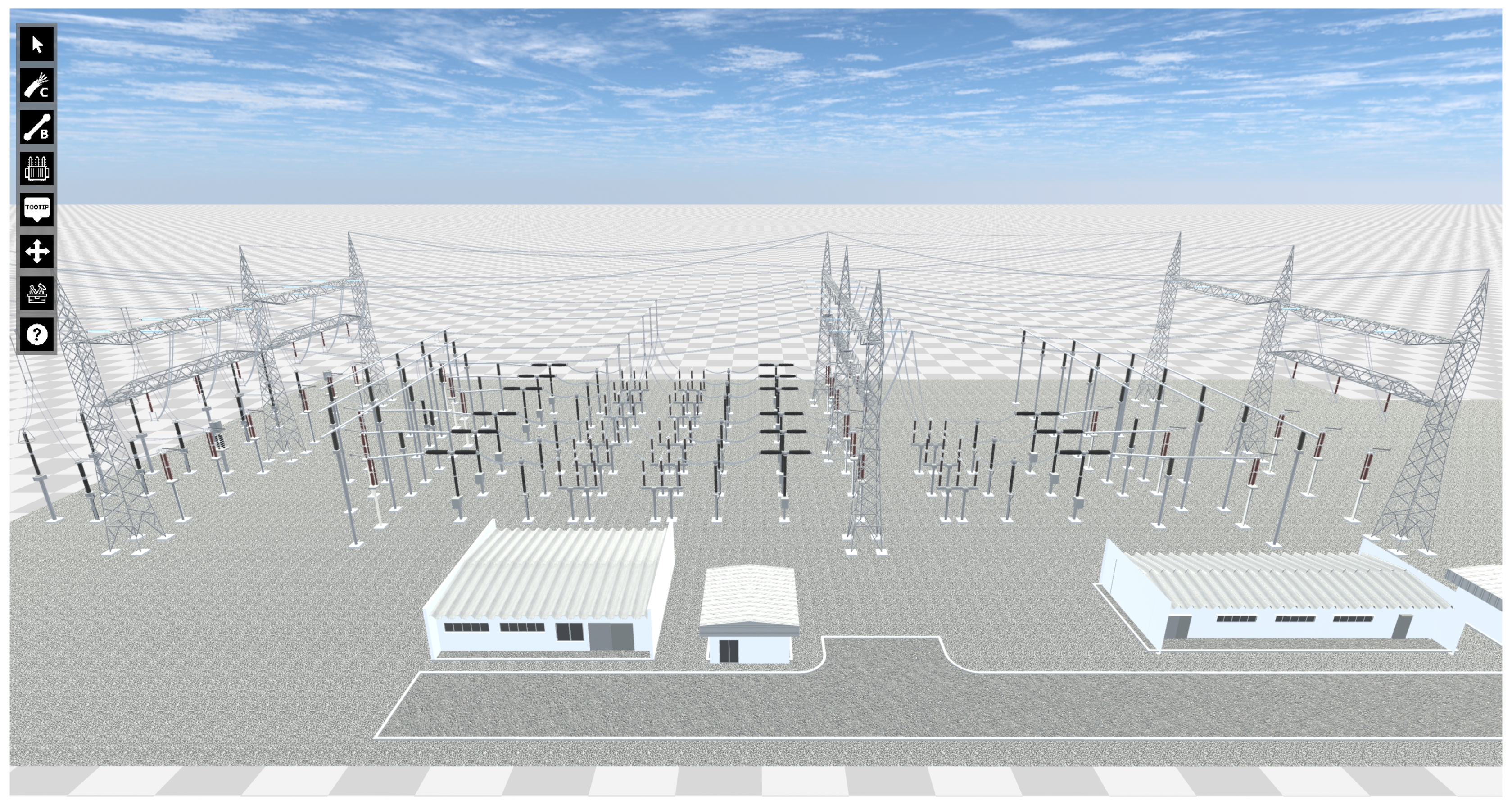
  • Virtual Reality Software: used by the end user to navigate and interact with the VE.
In cases where they apply the VRS to the supervision of real field equipment, they propose use of servers, which supports the SCADA [33], used in industry for data acquisition and asset control [34]. The Local Server component is responsible for this task. As a result, it is possible to realize the transference of information between the field and the VRS, thus enriching the virtual representation with the real state of the assets.
Figure 2 gives a detailed presentation of the conceptual diagram of the AS and its features. The VEM is the module responsible for managing the virtual assets of the AS, as well as it provides services to external applications. They developed using the client–server concept that employs the Django framework [35]. The Database Management System (DBMS) manages the relational database, stores references for the project file, 3D models, symbols, floor plans, asset identification codes and EPS equipment reference pictures that refer to real objects. The VEM also features a 3D model visualization tool, with rendered images, produced automatically by the Blender suite [36] during the 3D model registration process. Finally, to facilitate the connection of external software, an Application Programming Interface (API) was proposed based on the Representational State Transfer (REST) architecture, commonly used in modern internet services [37]. Files in XML and Json format were used to perform the serialization and deserialization of the data that travels over the network. In order to users keep records and control of all inputs in a simple fashion, a web application is necessary, as represented in the component denominated Website.
CADE was developed using the frameworks Microsoft .NET and AutoCAD .NET [38]. As such, the software implemented in three main modules: the Project Manager, the Floor-Plan Manipulation and the Deployment Manager. The VEM provides user access control with credentials.
The Project Manager module is responsible for controlling the floor plan project. It uses the VEM user authentication system, allowing the access and filtering permissions access for user projects, version tracking. It also configures the levels (height) of the elements of the drawing in relation to the ground, it reviews all the elements through report data extraction and the communication with the deployment module to integrate the design into the VRS.
The Floor-Plan Manipulation module is responsible for the project design process on the floor plan. It has the tools needed for insertion and creation of symbols, element identification, definition of levels and the preview of the floor plan in 3D. It also allows access to VEM to obtain of symbols through adjustable filters. The module also has the creation tools and attribution of the symbols to the 3D models registered on VEM. The process is performs through the selection of the symbol and the 3D model. The 3D preview is executed in parallel with CADE in 3D software derived from the VRS, which uses the same reconstruction components as VEs.
Finally, the Deployment Manager module dedicates to the processes of integration between the CADE and VRS. The process is performed through floor-plan attribute extraction scripts. Then, the generated data structures are used to incorporate the element metadata and the application of a metamodel to an integration file.
The VRS is used by the end user for specific tasks in the Virtual Environment. It has five main modules: the Management Core, the Download Manager, the Directory Manager, the Local Files Encryptor and the Reconstruction System. The modules were implemented using the .NET framework and Scripts in C#. The Management Core is the primary module for execution during software initialization. After the initial procedure, a connection made with VEM to obtain a list of floor-plan projects implemented in VR. Upon selecting a project, a Hypertext Transfer Protocol (HTTP) request is sent to VEM, requesting the Integration Data with the information of the VE, which are then analyzed and a report is generated in which are found the inputs necessary for downloading and reconstructing the VE. The input is then downloaded by a Download Manager and directed to the Local Files Encryptor through Directory Manager, which is responsible for placing each download and encrypted file to its standard directory. This way, encryption and decryption algorithms are used to guarantee security against devices and the integrity of local files.
The Reconstruction System is responsible for reconstructing the Virtual Environment from the Integration Data, with all the attributes and features defined in the floor-plan design process. It uses a third-party library called Trilib [39], appropriate for reading and creating instances of 3D models in Filmbox (FBX) format in the VE on Unity.
Finally, applications destined to asset supervision, can perform connections by the Internet with the server SCADA. As such, Management Core makes periodic requests to obtain the state of each element in the real environment.

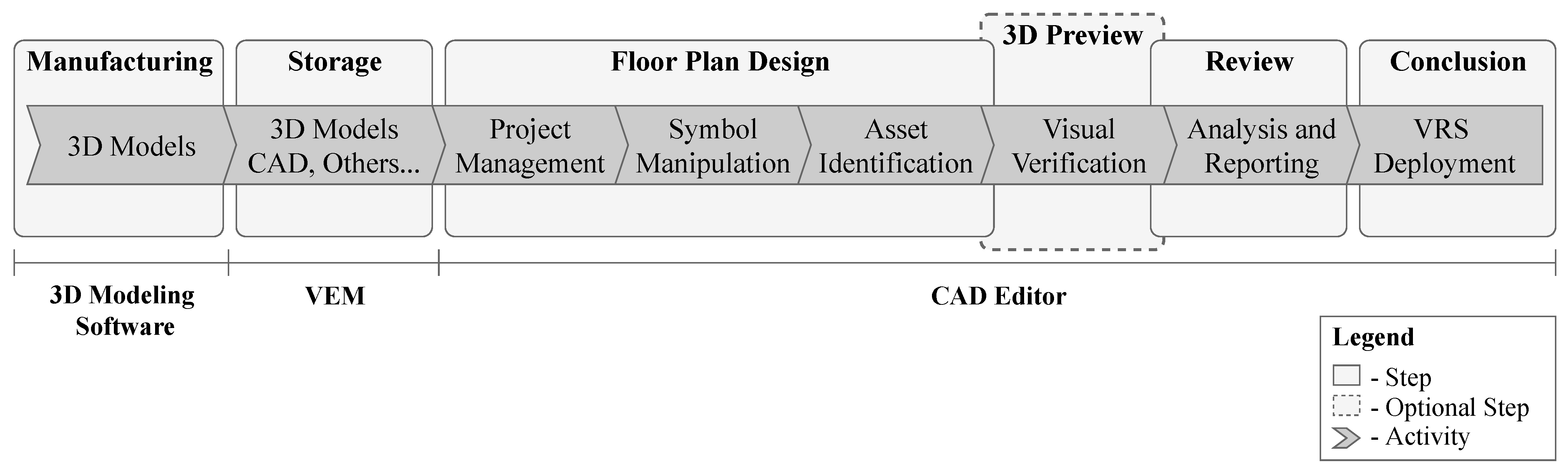
3.2. Authoring System Methodology

The AS is a toolkit developed to elaborate and customize VEs to VR through the floor plans and with support from the software AutoCAD. The design approach of 3D virtual scenarios through engineering drawings in floor plans is one of the important aspects of the proposal.
The development of three-dimensional VEs has many aspects that influences the usability of the tools, as well as user performance. According to Nielson et al. [40] the 3D data, the input techniques present problems due to the two-dimensional nature of the screen monitors and interaction devices, as well as visualization disruptions at certain viewing angles, element occlusion and visual clutter. It is believed that the symbolic representation of a real environment, as it is the manipulation of elements in two-dimensional space, provides abstraction and reduces visual overload during development.
Figure 3 presents the design stages of VEs using the AS and geometric modeling software. The steps defined as manufacturing of input, storage, floor-plan preview, review and conclusion.
First, it performs the virtual asset manufacturing stage. Thus, 3D models are produced using geometric 3D modeling software, such as 3Ds Max [41], Blender or Inventor [42]. During the process, the use of conventions in 3D modeling rules guarantees the same result regardless of the software.
The manufactured inputs are stored in the second stage. Three-dimensional models, floor plans, asset identification code, documents and photographs are registered on VEM through a website. In this stage, users can register 3D models and provide information such as the element class, category, reference pictures, symbols, design, etc. The floor-plan design stage is the process of planning the representative design. Therefore, specific tools for manipulation and management are used for each activity involved. The related activities are:
  • Project Management: routine activities such as user authentication to VEM, selection of user floor-plan design, configurations of element levels (height in relation to ground) and store version history of actual floor plan;
  • Symbol Manipulation: search, insert, edit, substitute, erase, move, rotate and scale the symbols that represent 3D models of assets;
  • Asset Identification: attribute the code to the symbol when the VRS is destined to supervision of field assets. This stage can be performed at the moment of symbol insertion into the floor-plan design.
The 3D preview is an optional process. This stage relates to the visual enhancement and the improvement of the mental model of the user [43]. As a result, it is possible to visualize the floor-plan design in a 3D environment. The visual 3D review is important for detecting possible errors and problems regarding the design process, thus reducing reworking, time and final cost [44]. In this sense, it is possible to preview its final state before implementation on the VRS. The preview has the same rebuild core as VRS, but runs in parallel with CADE.
The review stage should be performed before the implementation of the project on the VRS. A detailed analysis is performed for all assets regarding the topological connection between elements (when necessary) and elements are identified. All the activities are performed through automated tools and, at the end, a report is presented with any detected problems.
Finally, the conclusion stage is responsible for carrying out the data extraction process for the project and integrate these with the VRS. The data are stored on the VEM automatically and tagged as “project under development”. Thus, the integration data can be accessed by the VRS.

3.2.1. Symbol Manipulation on the Floor Plan

The initial floor plan is a blank 2D CAD document, provided by the CAD software, where the user inserts 3D models symbols. Another way to prepare VEs is to use a ready-made floor plan and register the symbols drawn on it. This way, it is possible to reuse projects and enrich the library of 3D models and symbols.
The manipulation of symbols on the floor plan performs using the tools in CADE and the software AutoCAD. Noteworthy here is the use of AutoCAD in the proposal presented this study, as it many native tools necessary for manipulating the design elements, such as move, rotate, scale, copy, paste, cut and many others.
The symbols are two-dimensional (2D) representations of the 3D models stored on VEM. Therefore, the 3D models should beforehand be registered on the VEM and then the symbols should be designed and attributed (linked) to the models. To create a link between a 3D model and a symbol the user must select the symbol for registration and then the 3D model to be attributed.
A request of the type HTTP/POST is sent to the VEM through the Uniform Resource Locator (URL) http://server:port/api/symbols/, carrying the following information:
  • Block: CAD symbol in the base 64 format for sharing via internet;
  • Thumbnail: rasterized thumbnail of the symbol;
  • Description: description of the element;
  • Objects3D: identification code of the 3D model to which the 3D symbol was attributed.
The insertion of symbols is performed through a tool implemented with features for performing searches, selection and insertion of design elements. First, the user performs the search filtering through class, description or element code. The VEM services then returns a list of symbols presenting thumbnails of images and other data. After selecting the desired symbol and executing the process of insertion into the design, a request HTTP/GET is sent to the VEM through the URL http://server:port/api/symbols/?id=1, where the snippet “id=1” represents the identification of the selected element. Following this, the AS receives the requested payload, which contains information on the symbol and the 3D model:
  • Fingerprint: global symbol identification in the VEM database;
  • Thumbnail: rasterized thumbnail of the symbol;
  • Block: CAD symbol in base 64 format for data serialization via the Internet;
  • Description: element description;
  • Object3D: identification code of the 3D model that the symbol represents.
With the payload in the system memory, the process of converting the code into base 64 of the element “block” to a CAD symbol is executed. Next, the symbol is presented inside the AutoCAD viewport with the editing floor plan. The user is then prompted r to provide the rotation value (in degrees) and the position in the plane for its correct positioning. The insertion tool performs an injection of attributes into the symbol, as presented in Figure 4, which refers to an electrical device. The attributed information is important metadata for the integration process. Metadata are defined as data on other data, these are sets of information that provide a structured reference for another category of information [45].

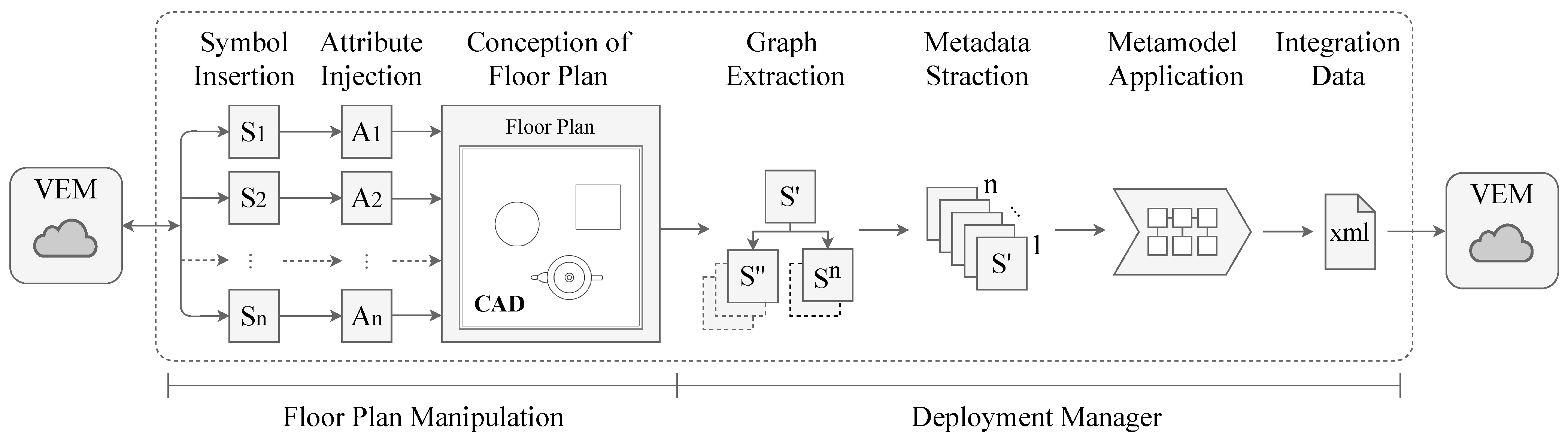
3.2.2. Integration between the CAD Editor and Virtual Reality Software

The process of integration between CADE and VRS is accomplished through the adaptation of the element data inside the floor plan in a file containing all identification, positioning, rotation, topology, hierarchy and metadata information.
As the floor plan and the VRE have different dimensional spaces, there is a challenge of reproducing what is on the 2D to 3D plane, without the need for manual action from the user. Thus, the integration strategy proposed is achieved through the extraction of information from each entity inside a given floor plan into graphs maintaining the hierarchy and the use of metamodel to define the format of the integration file.
As presented in the previous section, for each symbol inserted into the floor-plan design, information from VEM is attributed. For instance, information from the 3D models registered contain metadata referring to the element class, description, category, related projects and their identification, in addition to photographs and documents. Hence, the entities are rich in essential metadata for the reconstruction of the scenario in VR.
Figure 5 presents the conceptual diagram of the floor plan design process through the insertion of symbols, along with the process of extracting and adapting data for integration between CADE and VRS. In the manipulation stage of the floor plan, the symbols are obtained from the VEM and then inserted into the diagram. Subsequently, when requested by the user, the integration process is executed and carried out in three steps:
  • Extraction of graph structure: this process obtains all the relationships between symbols in hierarchical form and stores these temporarily in a data in memory structure;
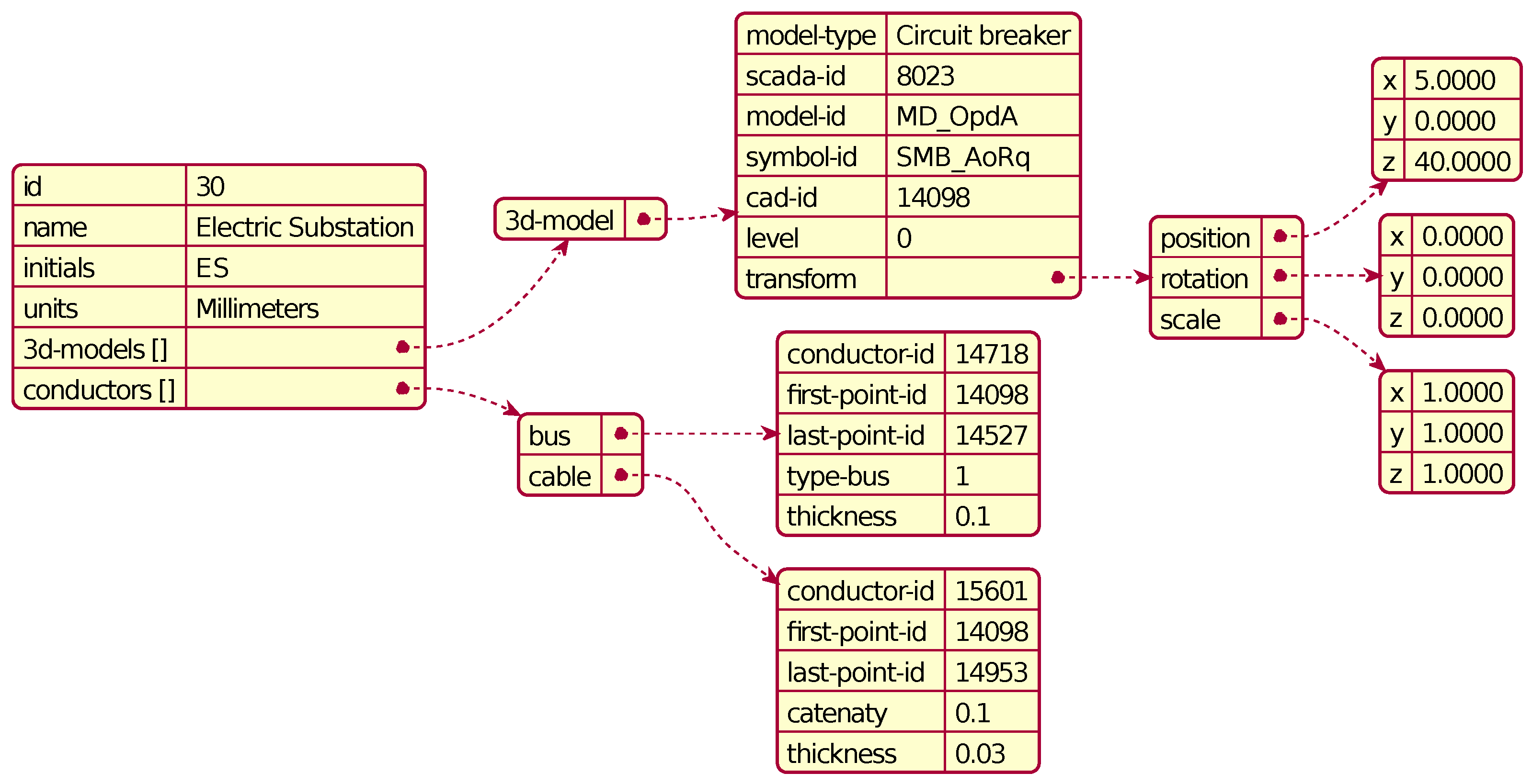
  • Extraction of metadata: this process extracts the attributes of the symbols inserted during design manipulation. Furthermore, additional information is extracted, such as the transformation matrix (position, rotation and scale);
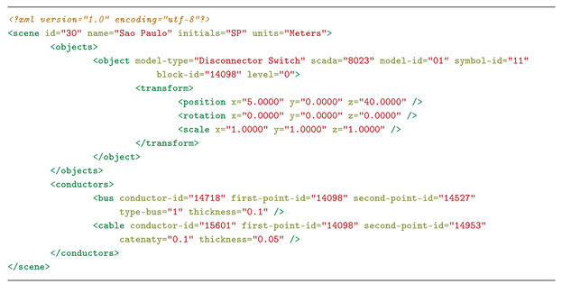
  • Application of the Metamodel: this process organizes the graphs and the metadata into one unified data structure. In this stage, the data are organized into referenced blocks, maintaining the hierarchy of the elements. All the information is stored in an XML file and used to send data over the internet.
Thus, at the end of the integration process between CADE and VRS, an integration file is submitted to VEM and assigned to the EPS project. The file contains all the data and metadata of the elements extracted from the floor plan. The Listing 1 exemplifies an EPS integration file in XML format, containing only one equipment and two types of electrical conductors.
Listing 1. Sample data from an Electrical Substation integration file in XML format.
Energies 14 07435 i001
Figure 6 presents the conceptual diagram of the integration data recovery and information extraction process to perform the scene reconstruction on the VRS. The VRS connects to the VEM through the internet and obtains the project integration file for preview. Through the predefined structure of the metamodel used, a script performs data extraction and converts it into a 3D model lists to be downloaded (when necessary), along with the metadata with information concerning the construction of the 3D Virtual Environment.
The download of the 3D models is performed in three stages. In the first stage, a verification is made in the local directory to obtain the models already downloaded. In the second stage, each local 3D model is compared through a checksum value to those stored in the VEM. In case of a detected difference, the local model is updated. Finally, in the third stage, the download is performed for all the models not present in the local directory. The process is performed before the reconstruction of the scenario, thus guaranteeing access to all the local models.
After the download of all 3D models, the reconstruction process is initiated. This process is executed in four stages:
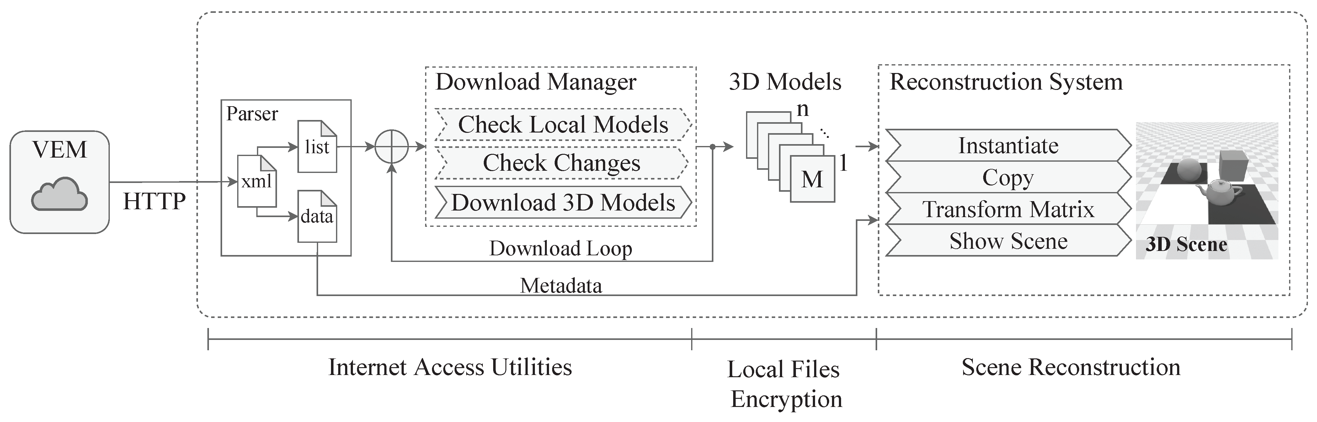
  • Instantiate: a model of each type is instantiated in memory and remains until the end of the reconstruction of the scene. This process is performed by the Trilib library [39], which is costly in terms of processing;
  • Copy: after the 3D models are instantiated in memory, the reconstruction system makes copies of each model, using the metadata as reference from the integration file. This process is less costly and reduces scenario reconstruction time;
  • Transform Matrix: after copying the 3D models, the transformation matrix is applied to each 3D model for its spatial positioning (position, rotation and scale of each element);
  • Show Scene: when the reconstruction process is completed, the VE containing the positioned assets is then presented to the user.

3.2.3. Geometric and Symbol Modeling

The standardization of the 3D models and symbols are fundamental to ensure the correct operation of the floor-plan design and the reconstruction of the VE by the VRS. Thus, a geometric modeling convention is proposed in this section. A convention modeling is also used in the study by [46], for a building construction project.
Regardless of the geometric modeling software, the elements created in CAD software or parametrically can be designed and suited to the AS when applying the convention rules. As a consequence, the modeling convention enhances the possibility of using 3D models from different sources, including those created by manufacturers or developers. The conventions for geometric modeling are:
  • Object dimensions: the dimensions should be identical to real object, maintaining the physical and constructive aspects;
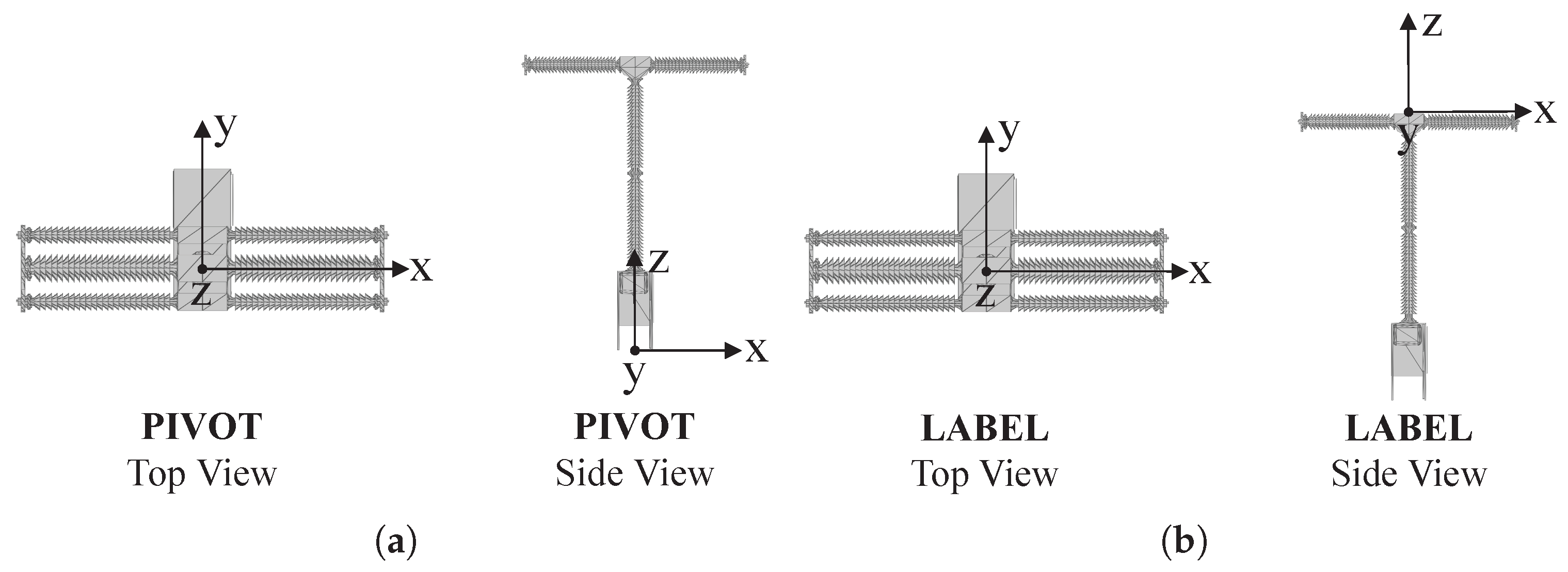
  • Object center (pivot): the object should have its pivot point in the mass center of the model, centralized on the XY plane and with the Z axis corresponding to the lowest level (Z = 0 in relation to the object), as demonstrated in Figure 7a;
  • Object label: the label is used to aid the positioning of graphic elements or texts above the object. Its usage is optional. An empty element or dummy known as “label” should be inserted and positioned in the mass center of the object with displacement on the Z axis until the highest point (Figure 7b);
  • Object scale: the scale of the model should be analyzed whenever possible, thus ensuring that it has values on the X, Y and Z axes (without changes to the geometric aspects).
The symbolic modeling is performed through the CADE with the aid of CAD tools. The conventions for maintaining the representation and operation of the system are:
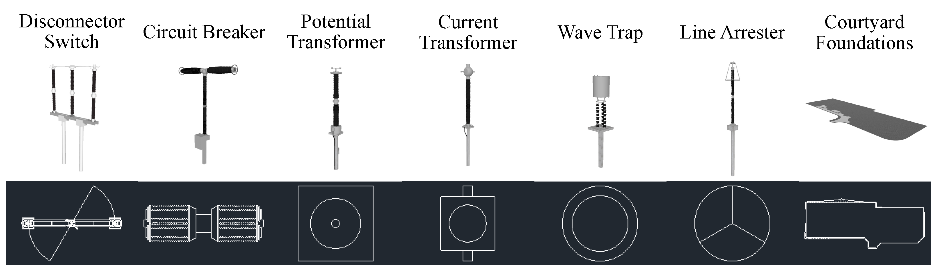
  • Symbolic representation: the symbol should be designed representing the 3D model in top view;
  • Similarity with the 3D model: the designed symbol should represent the 3D model with a high similarity;
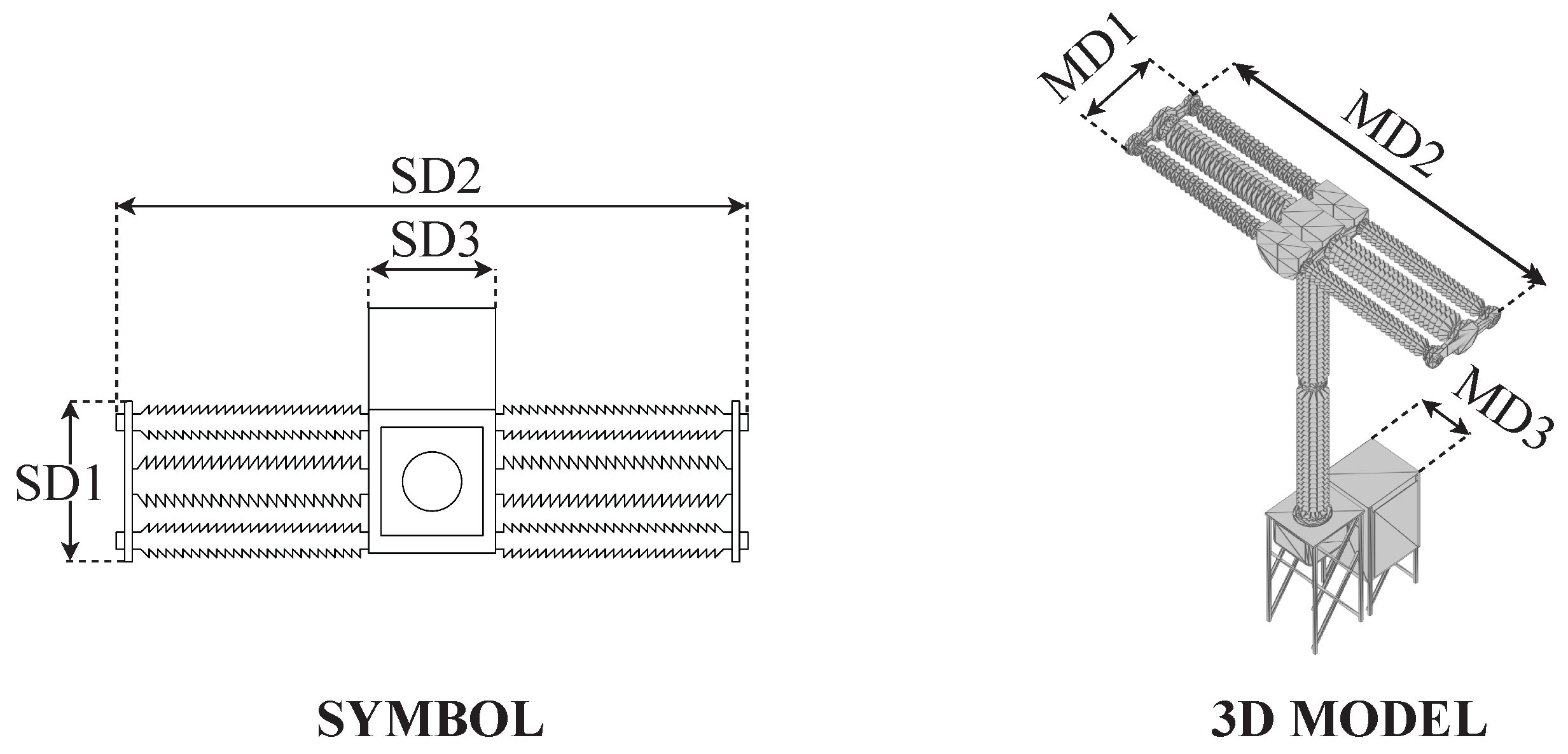
  • Dimensions: the dimensions of the symbols should be equal to those of the model. Figure 8 presents the equality between dimensions of a symbol and its 3D model, where S D 1 = M D 1 , S D 2 = M D 2 and S D 3 = M D 3 .
  • Center of symbol (pivot): the symbol should have the pivot point on the XY plane positioned on the same pivot point as the 3D model on the XY plane;
  • Measurement unit: the symbol should be created without a unit of measure (dimensionless), so that when used on a floor plan it will be attributed automatically with that value already in use.

4. Experimental Evaluation

This section discusses the evaluation applied to the development of EPS for VR. Here, a Case Study is presented during a Research and Development project (R&D) for a power company. Adaptation in the architecture to support the software of the power company are also shown. Finally, the improvements in geometric modeling convention are added and presented. Therefore, to validate the effectiveness and the feasibility of the solution, a real EPS was elaborated using the AS.

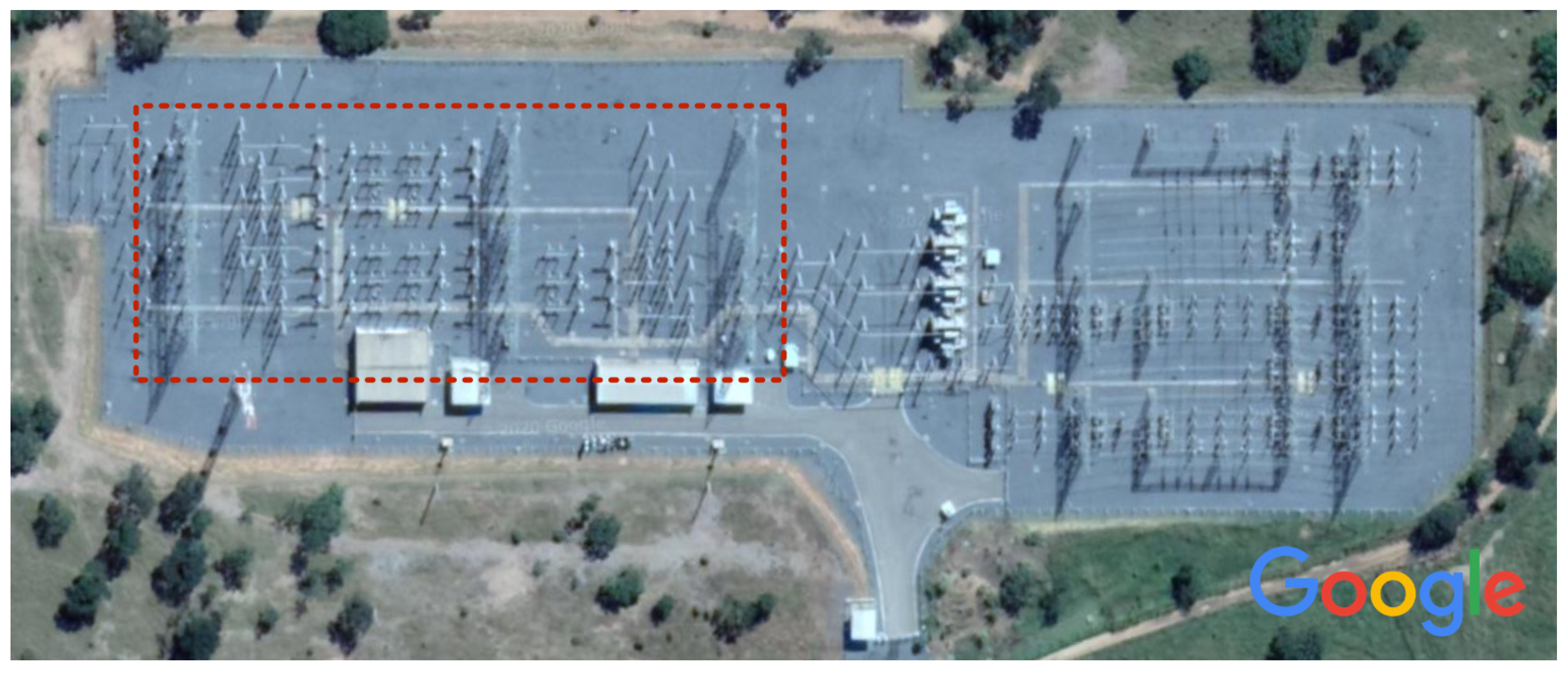
4.1. Case Study Applied to Electric Power Substations

The experimental evaluation was performed through a Case Study applied to the R&D project of a large electric utility company, which covers the countrywide supply of electricity in Brazil. The project covers VR research topics for the supervision and training of critical electric power systems, as well as in human-computer interfaces, which empower the three pillars of VR: interaction, immersion and imagination [47].
The initial strategy adopted for designing VR scenes employs teams specialized in geometric modeling, programming and level design. Hence, the scenes are produced through manual methods with the game engine Unity. Only parts of the development process are performed through automated scripts, as in the insertion and substitution of objects, listings of elements in the scene and the process of creating the executables of the VR software. Even with the automation of some processes, there is a lot of manual work and time invested in the current methodology. This way, the production and maintenance of virtual EPS becomes arduous when considering the processes of implementation, maintenance, time, quality and specialized teams.
For the Case Study and the proposed evaluation, the design of a floor plan of an EPS was performed, which operates at a voltage level of 345kV in an area of approximately 28,000 m2. Figure 9 presents a photograph of the EPS taken by a satellite. The traced area represents the assets belonging to the company. There are 184 elements in total (structures, equipment and constructions), in which 54 are supervised by the local SCADA server and transmitted to the supervision center.
The EPS is composed by disconnector switch, pantograph switches, circuit breakers, current transformers (CT), potential transformers (PT), lightning rods, gantries and other important elements. It has two breaker-and-a-half topologies connected to two buses, with a transmission line connection to a hydroelectric power plant and to another linked EPS.

4.2. Adaptation of the Methodology to the Context of Electric Power Substations

The proposed architecture allows modification, for expanding its use by adding new components. The architecture proposed in Section 3.1 considers the connection to a supervision and asset control systems through a SCADA server layer; however, when necessary, one can add new layers to the system to suit a given purpose. This is the case of systems involved in R&D, which contain a server layer responsible for the supervision of assets over the internet.
In addition, it is possible to add new rules to the geometric modeling convention, standardizing its aspects to a specific application.

4.2.1. Web Service Layer for Asset Supervision

The electric utility company system has a web service to centralize all the data from field supervision. Through a proprietary communication protocol, the information is transmitted in real time to the centralized server, where it is shared among the EPS operation computers. This secure system has data and access protection. Therefore, for the evaluation of the proposal, only a limited consultation of the data was made available.
To enable the communication between the VRS and the EPS assets, a server layer was added denominated as Power Company Web Service, as presented in Figure 10. The asset data of an ESP are sent in real time to the Web Service and made available through the internet in a secure communication through a Virtual Private Network (VPN). Through the VPN, the VRS sends periodic requests to the users of the information system for each manageable EPS asset.

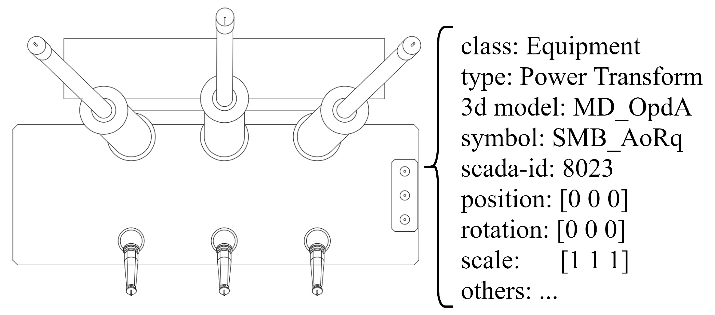
4.2.2. 3D Model Conventions

The EPS equipment is known to have some particularities. For instance, there are electrical connections through conductor cables and buses. In addition, these devices are fixed onto structures to the ground with cement blocks to sustain the whole structure. Hence, the following geometric modeling convention agreements were added:
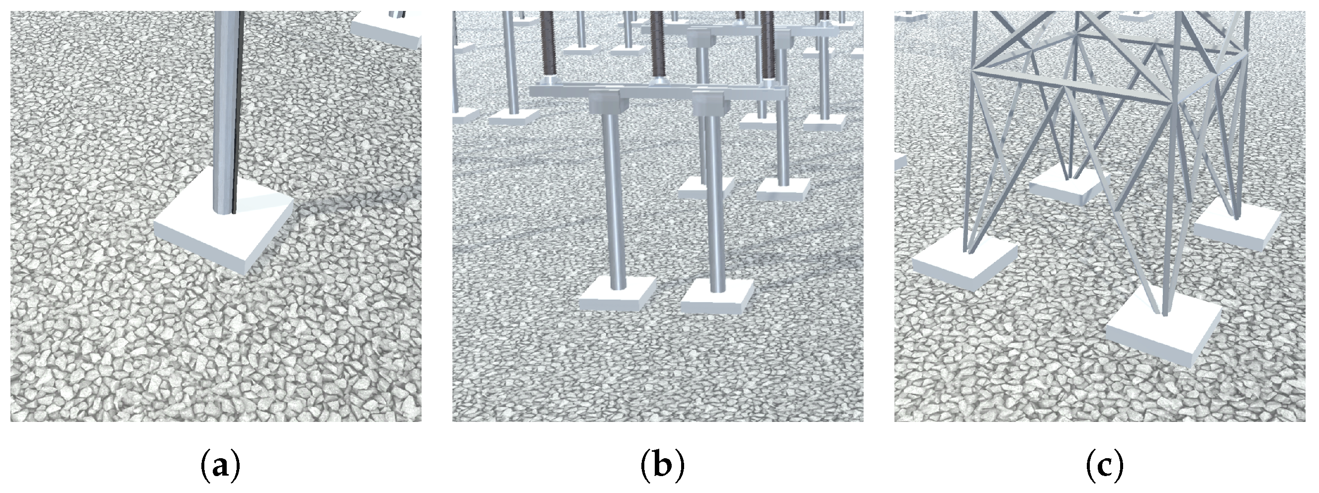
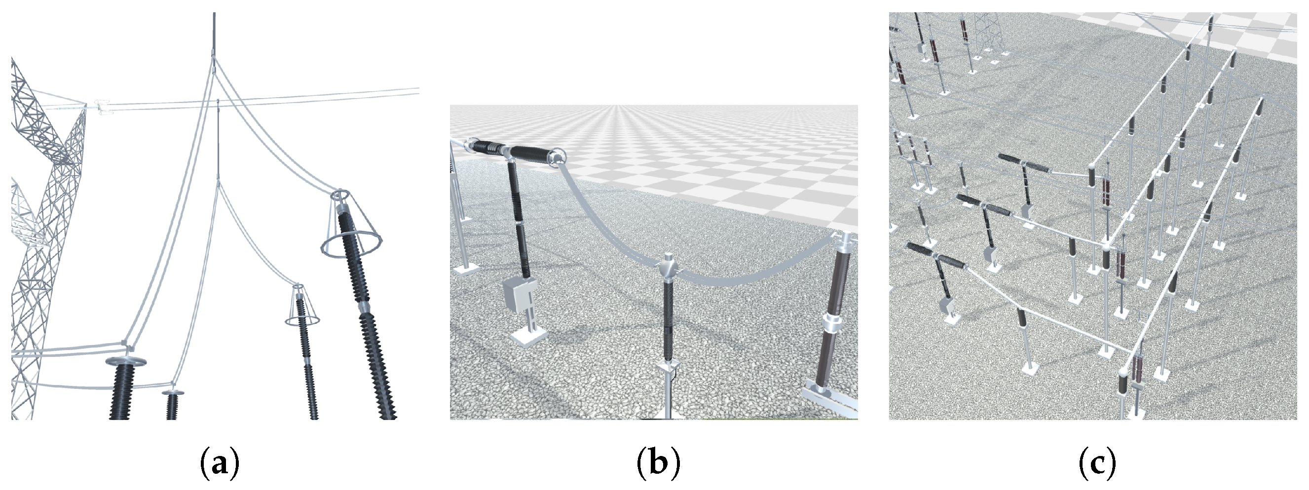
  • Connectors: elements responsible for anchoring the connection points of electrical conductors between two or more pieces of equipment, as presented in Figure 11a. Simple objects such as a box, cylinder or capsule should be created in cable connection regions and should be named “connector”, regardless of quantity;
  • Base references: elements that have two or more areas of contact with the ground should be referenced as dummy objects positioned in the contact areas. Figure 11b demonstrates the six references for bases in a part of equipment of the disconnect switch type.

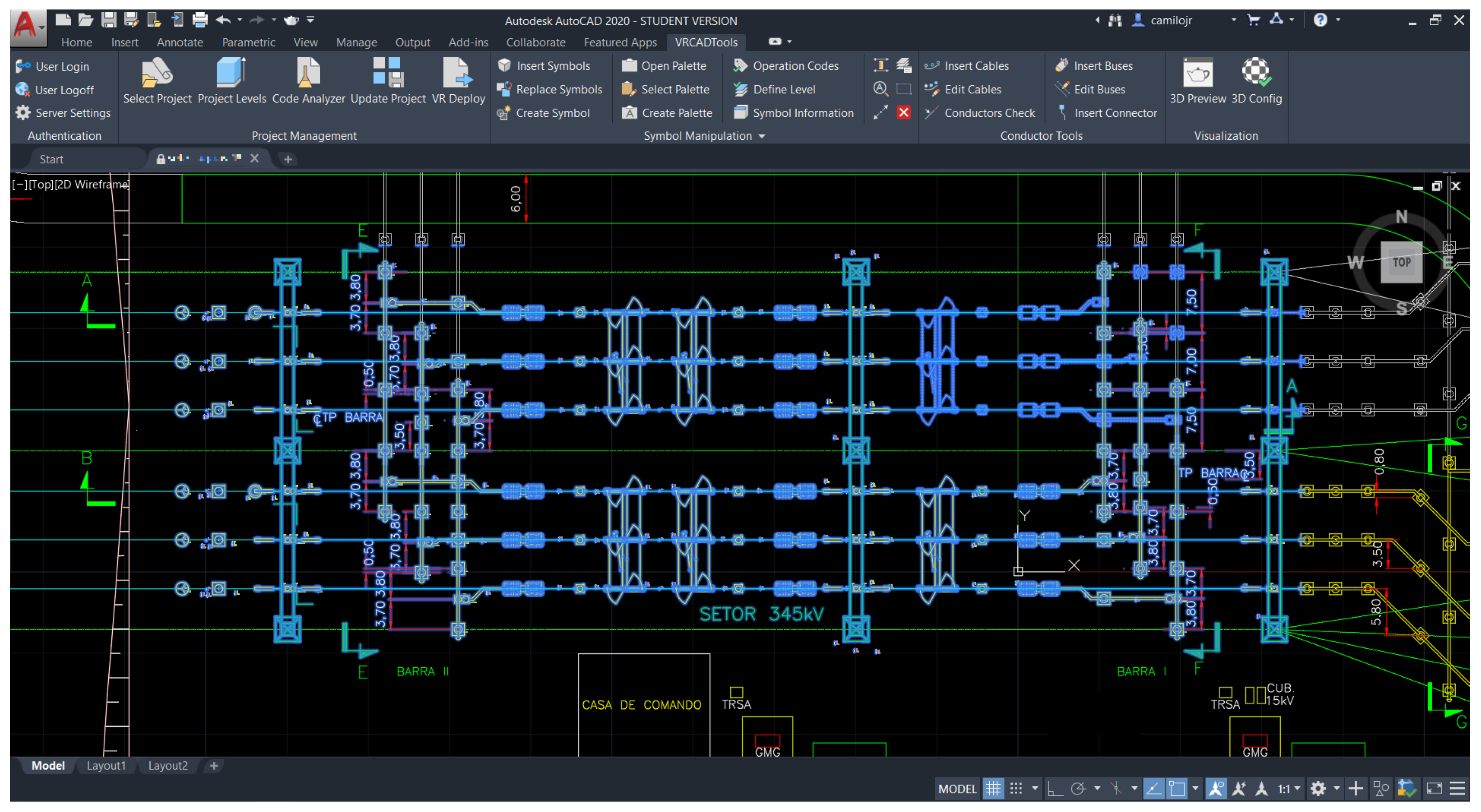
4.3. Graphic Interface of the CAD Editor

To improve usability of the CADE, keyboard shortcuts were created to allow fast access to the program functionalities. The software AutoCAD uses Ribbon menus in its uppermost section, grouping commands in the form of icons and buttons. Figure 12 presents the Ribbon developed to combine all the features in context groups, such as authentication, project management, symbol manipulation, tools for conductors and floor plans preview in 3D. The functions can be executed through access to the menu or by commands typed into an input field.
Each feature presented has a graphic interface. The goal is to provide a graphic display of the options and configurations of each feature, allowing the management and manipulation of all the elements in a way that is comfortable for the user.
Figure 13a presents the equipment search window, with a selection and insertion of symbols into the floor plan. In the figure, it is possible to note the search filters at the uppermost part. At the center there is a list with a symbol and at the lower part a configuration for inserting objects inside the drawing. Figure 13b presents the system for creating and assigning symbols to 3D models registered in the VEM. First, the user is requested to select the symbol on the floor plan, then search and select the 3D model. Finally, after clicking on the button “Register New Symbol”, the symbol is registered on the VEM and assigned (linked) to the selected 3D model.

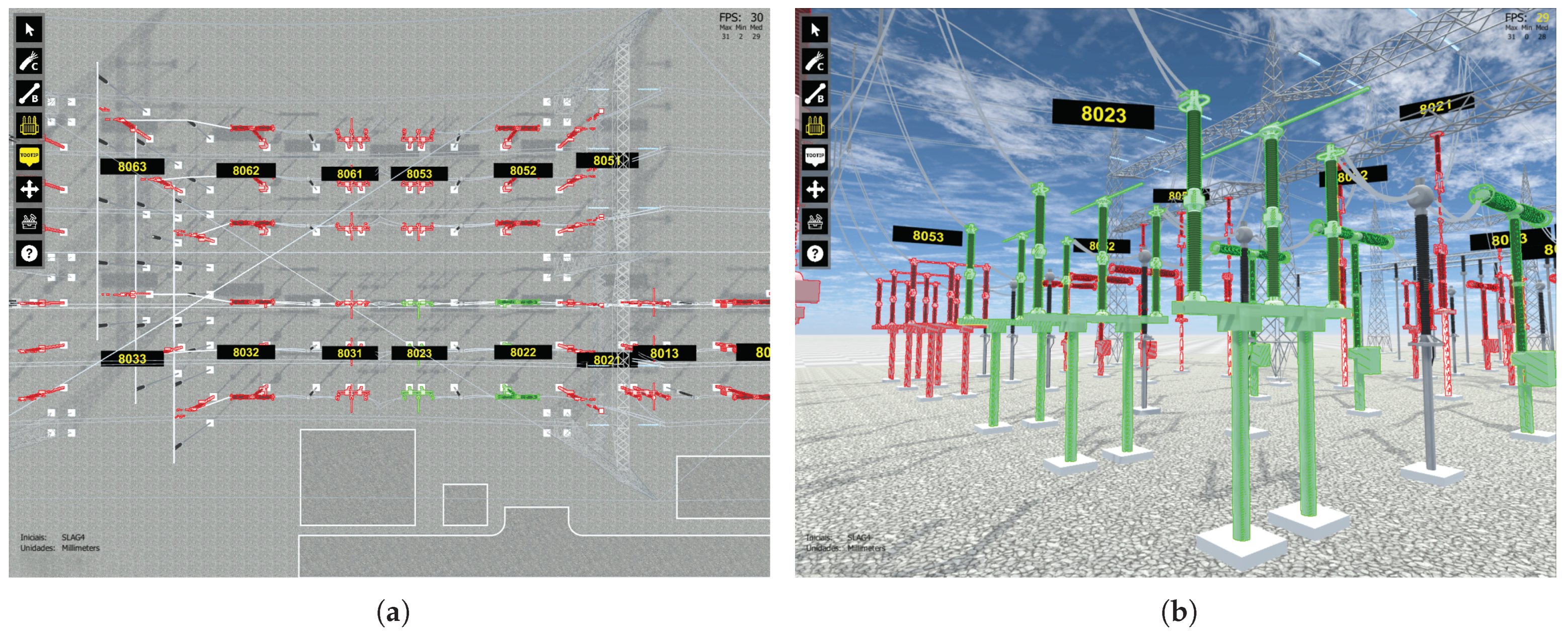
4.4. Integration of Design into Virtual Reality

The information from the floor-plan elements was compiled and converted into integration data preserving all topological aspects, while also combining equipment metadata in a single integration file. Figure 14 exemplifies the data structure of the integration file to the EPS context. The diagram presents the main node of the scene, which includes a list of 3D models and conductors. The element “3d-models[]” represents a list of 3D models that belong to the scene. Each 3D model has its own metadata for identification, relationship with other objects and its transformation matrix. The element “conductors[]” represents the list of conductors that connect the equipment. It is possible to see the bus type and malleable cable.

4.5. Development of the Electric Power Substation

In this section, the development stages of the EPS are presented. First, the geometric modeling of the equipment is presented, along with the preparation of the floor plan through of the AS.

4.5.1. Geometric and Symbol Modeling

Initially, the EPS data were gathered for geometric modeling references, such as equipment reference pictures, videos, diagrams and CAD files. The 3D and EPS symbol modeling were created by applying the convention rules. The software used for the task was AutoDesk 3Ds Max. Figure 15 summarizes some elements that have been modeled and used for the evaluation. The symbols were extracted from the floor plan provided by the power company. Then, they were registered in the VEM and linked to its corresponding 3D models. In total, there were 13 models of equipment designed in 3D, along with 3 non-equipment elements (land, control house and compressor house).

4.5.2. Preparation of the Electrical Substation Floor Plan
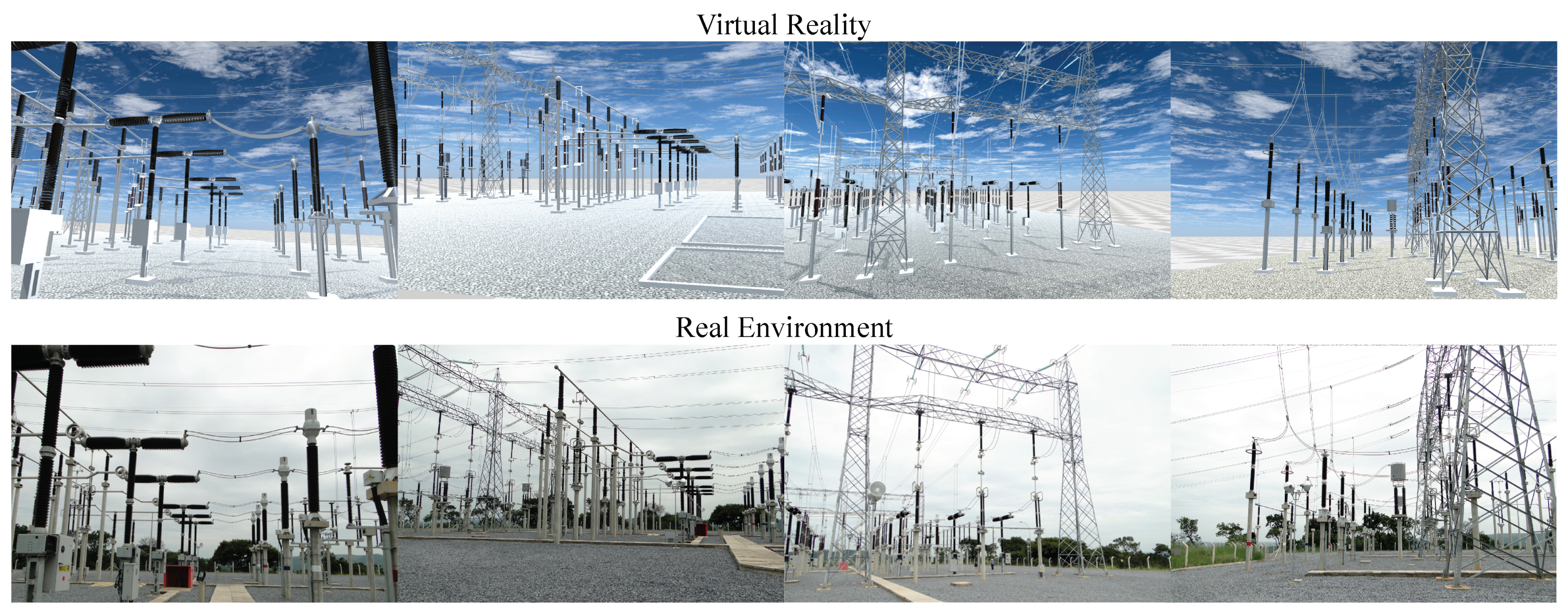
The process of preparing the floor plan followed the design stages of the VEs presented in Section 3.2. The models were designed and registered in the VEM with its data (reference pictures, equipment class, operating voltage, manufacturer and an unique identification code). Additionally in the registration stage, a new EPS design was added, containing a CAD plant provided by the power company.
The development was initiated by inserting the configurations of the floor plan into the CADE, with ground level starting at 0 m and the equipment levels at 0 m, 14 m and 20 m. As such, the majority of the equipment remains at ground level, except the insulators and gantry bridges that support the overhead bus bars. The symbols were filtered and inserted into the design and positioned according to the floor-plan template provided by the power company. The electric conductors were added subsequently. Figure 16 presents the floor-plan design of the EPS, the selected items represent the inserted symbols.
After performing all the insertions and completing the EPS design, a detailed review was done for all the elements, with the aid of tools developed for this purpose. Therefore, verified the consistency of the equipment identifiers for supervision and the integrity of the conductor connections. This stage is important, as the extra identification guarantees the supervised equipment is correct, thus avoiding incorrect readings of the real equipment state.

4.6. Results

The VEM system was deployed in an Amazon Web Services (AWS) server, using the Elastic Compute Cloud (EC2) service. The associated services were made available by means of the API developed with the Django framework. During the design period of the EPS, the existing virtual assets were registered and used without connection problems or system failure.
As it is a centralized architecture, external applications remained synchronous, receiving real-time information on changes made to the floor-plan drawings. Figure 17 presents VEM deployed on AWS, showing the gallery of 3D models.
The process of preparing the virtual EPS were done in the design stages of the VEs. Users were granted access to the VEM and CADE, along with the registered virtual assets. The floor-plan design was produced using the manipulation, review, and implementation tools on CADE. The review of all the elements for the identification of problems was performed, along with its correction. Finally, the EPS was implemented and made available for access via the VRS. Figure 18 presents the virtual environment from the EPS on the VRS, reconstructed from the integration data and through the reconstruction module.
The use of geometric modeling conventions and symbols presented a valid strategy to simplify the elaboration of the 3D scene. The defined rules were used in the 3D models and symbols, making it possible to create the scene from the floor plan and to integrate it into the VRS. Figure 19 demonstrates the employed conventions for ground support bases in equipment assets. Noteworthy here is the use of 1 (Figure 19a), 2 (Figure 19b) and 4 (Figure 19c) bases, all of which were added to the VRS automatically during the reconstruction process, increasing the physical and visual credibility.
Figure 20 presents the result from employment of conventions for connectors. The Figure 20a demonstrates the malleable cabling between the ground equipment and the aerial bus. The Figure 20b exemplifies the connection between equipment. Finally, Figure 20c shows the equipment connected to a rigid bus. The automatic insertion of conductors is performed after the positioning of the equipment, performed by the Reconstruction Module.
Figure 21 presents the results for the supervision mode of the VRS, using a state simulation provided by the power company. This mode of visualization enables the visualization of equipment states in real time, while navigating the VE. Above the three-phase equipment, there is an identification label with the operation code used by the supervision system. Figure 21a demonstrates the top view of the EPS and the identification of the equipment in the arrangements. The elements highlighted in red represent the equipment in a closed-circuit state (energized) and in green in an open circuit state (non-energized), as defined by the power company. Figure 21b shows first-person perspective view for the circuit breaker identified as code 8023, highlighted in green. Please note that the cross arms between the terminals are positioned in an open circuit array, reflecting the visual representation of the state of the real equipment to the virtual.
The virtual environment of the EPS presented visual, constructive and behavioral credibility. The reaching of such fidelity is the result of the geometric modeling, using as a reference CAD documents, diagrams and equipment reference pictures. The constructive credibility achieved herein is the result of using CADE and the reconstruction system of the VRS, which processed and applied the transformation matrices (position, rotation and scale) to the virtual assets and insertion of the electric conductors. In addition. Moreover, it was possible to represent the behavioral and equipment states through visual information (labels and highlights), as well as the disconnector opening and closing animations. Figure 22 presents comparative images of the VE for the EPS and photographs of the real environment.
One problem in the manual conception of VEs for engineering, concerns the errors in accurate positioning of the elements within the scene. In some situations, the difference in the position between the scene and the floor plan can lead to technical problems when it comes to maintenance, as well as to materials during the training processes or construction planning.
Figure 23 presents a bubble chart showing the positioning errors in the manual conception methodology compared to the AS (using the CADE). Each bubble represents one equipment in the floor plan. The radius of each bubble is proportional to the difference between the manual and the automated (AS) equipment position methodology.
The bubble diameter represents the positioning error in Euclidean distance from the VE, produced manually in relation to VE against the one produced by the CADE. Error values range from 6.5 mm and 1221.7 mm. The error average is related to the elements above ground level, as for example gantry bridges and insulators for overhead cabling.
Figure 24 complements the information on positioning presented in Figure 23. The plot presents the 3D positioning of equipment, on which the XY plane represents the equipment position in the ground and the Z axis represents the equipment height. The color of the bubbles also represents the height in relation to the ground, where values of Z 0 are in blue, Z 15 m are in orange and Z 20 m are in brown. There is also the height variation at 0   m not visible on the graph ( 0.05 m, 0.02 m, 0.2 m) and near 20 m ( 18.85 m, 19.72 m, 19.78 m), thus demonstrating the inaccuracy of manual positioning. The diameter of the bubble represents the error in Euclidean distance between manual positioning and that of the CADE.
Around 76.58% of the equipment is positioned at ground level. The mean errors are characterized by the inaccuracy of manual positioning on the XY plane, which represents 52.27% of the positioning errors for the EPS produced manually.
Approximately 23.42% of the equipment is positioned above the ground. However, this high-altitude equipment represents 47.72% of error for the entire VE. Therefore, the error proportion is greater in equipment positioned above the ground. The inaccuracy of the positioning of aerial equipment might be related to the complexity of manipulating three-dimensional axes in 3D environments.
Given this difference in equipment positioning, the developed VE presents a higher precision positioning methodology.

5. Discussion and Conclusions

This study proposed an Authoring System based on the conception of Virtual Environments through engineering designs on floor plans with the objective of facilitating the development of scenarios to VR. A client–server software architecture composed of management solution software was presented. The methodology can be applied in many contexts, as for example in the design of industrial plants, architecture, marketing, and virtual expositions. In order to evaluate the proposal, a Case Study was carried out, which was applied to the development of EPS from a R&D project. Intrinsically, the methodology was adapted to the context and improved to attend to the needs of VEs for EPS.
The methodology proposed was shown to be important in large-scale production of Virtual Environments for EPS for supervision, allowing users with different experience levels to use the system. Due to the underlying theme of two-dimensional CAD, we believe that the Authoring System facilitated the design and adaptation of VEs using game engines.
The proposed software architecture was developed considering the gaps found in the related works, since they do not address integration management strategies between CAD and VR software in the context of EPS. Thus, the architecture provided internet communication between CADE, VEM, and the supervisory system of the electric power company.
The design process of EPS presented relevant results. It was possible to analyze the performance associated with the software architecture using the CAD Editor along with the VEM and VRS. The virtual assets (symbols, 3D models, floor plans, documents, etc.) were registered on VEM and used by the AS during the design process, thus demonstrating the reusability of elements in the design process. Consequently, instances of the VRS are kept up to date, thus ensuring that all the VEs used by the user are identical.
Symbol manipulation on CAD floor plans opens the opportunity for positioning with a high level of accuracy, as presented in Figure 23 and Figure 24, which demonstrate errors due to the manual design methodology of VEs. We also demonstrated that aerial equipment is more susceptible to positioning errors due to the complex task of manipulation in the three-dimensional space. Therefore, the method of Authoring System uses tools that are better equipped to deliver the correct position.
The positioning of elements in VE is relevant in situations that need precision, e.g., in simulations of equipment transport and truck traffic between arrangements. Another example is the analysis of equipment replacement and addition of substation arrangements, where the distances between the elements must be identical to those inserted in the floor plan.
The preparation process of EPS and its integration with the VRS showed good results. A real substation was built and integrated into the VRS. Its virtual assets were inserted into VEM and used during the production process of the floor plan, which allowed the reuse of the elements and better control of what is applied in the VEs.
The integration and reconstruction of the PHE were performed adequately, as shown in Figure 18. All elements drawn in the floor plan were positioned at their correct points, faithfully reproduced in the VR environment. Concrete bases and electrical conductors were created and precisely positioned. No errors were reported or observed during and at the end of the process.
The availability of the elements in the software architecture, opened the possibility of inclusion of a web service supervision, provided by the energy utility. Through the Internet, the VRS successfully accessed the data service supervision and presented to the user the asset states in real time during navigation. All visual information shown in Figure 21a,b comes from the metadata registered in VEM and assigned to the equipment during the floor-plan design. The colored visual representation of equipment state improved the perception of the operator while navigating in VR. Hence, it is possible that system operators follow and manage the assets in the field through VR.

Comparative Analysis

Thus, in order to reach the proposed methodology and obtain the results presented, studies and analyses of the related works presented in Section 2 were carried out. The studies provided the state of the art and attributes to delineate the research gaps and improve the integration processes between CAD and VR software for a virtual EPS Authoring System.
To identify the contributions and differentiate the methodologies used in the related studies, the following qualitative attributes were extracted:
  • CAD drawing category: two-dimensional or three-dimensional space used by the authors;
  • Virtual environment manager (VEM): asset management system used in Virtual Environments such as 3D models assets data (class, type, manufacturer, etc.), VE data (development status, 3D models used, designers, historical versions, etc.), CAD project, users and access control;
  • Integration method: manual, semi-automated (involves manual tasks) and automated;
  • Metamodel: system abstraction that describes the structural and/or behavioral aspects of the software, it is a definition of data structure of the integration file between CAD and RV software;
  • Graphs: data structure that defines the hierarchical elements of the model/scene. Used in elements with moving parts to animate actions and physical states;
  • Topology: definition of the logical relationships between design elements. Used to track the flow of electric current in EPS arrangements in order to represent, through simulations or supervision, the electrical state and functioning of the EPS;
  • Rebuild at runtime (RR): VRS performs VE rebuild during its startup is more likely to update quickly. This ensures that when accessing VEM and obtaining the latest substation update, the system rebuilds it and presents the most current version of the project.
From the characteristics extracted from the related works and the present work, Table 1 was elaborated.
Mattioli et al. [26] presents a methodology for designing VEs for EPS in a semi-automatic process using floor plans (2D). The work context is close to the present one, but the methodology does not provide an automated integration system with the VR software. The design is carried out through manual processes without rebuilding at runtime, requiring VR update at every EPS modification. Another important attribute for use in EPS is the asset topology, which was not used by the author.
Gebert et al. [27] discusses 3D modeling and the automatic integration process. The VR application and the work context do not address EPS, but it is related to the integration methodology, which uses metamodels to define the data structure of the integration file. An important feature of the work is the use of an element management system, increasing the control and sharing of VE information.
The works by [28,30,31], discussed the same characteristics as [27], except for VEM. The authors addressed the integration of three-dimensional CAD models with the automatic integration process. The relevant feature used in AS is the rebuild at runtime, which allows the VE to be updated and rebuilt during use.
In contrast, Zawadzki et al. [32], addresses a semi-automatic integration of parametric CAD models. The models are designed through parameters configured before the integration process, which has a manual work step. This attribute is adversity for the proposed methodology, as it generates an additional effort during the integration process.
The methodology proposed for the design of VEs for EPS through an AS is based on the characteristics of Table 1. Thus, the proposed methodology provided the AS with important attributes for the process of conception, integration, and use of VR. These features are significant for development facilities using CADE, VEM, and VRS functionalities.
Nevertheless, the AS has some limitations regarding symbolic representation. The symbols should be as faithful as possible to the 3D model. As a consequence of that, the process of designing symbols can be arduous. On the other hand, the symbol once designed and attributed to the object, becomes accessible and useful for any floor-plan design, characterizing its reusability. Another limitation is related to complex structures, where many levels or interposed elements are needed, such as a set of ducts in a petroleum refinery or the various floors in a particular construction. The overlapping of symbols can become confusing, since these are usually represented as a tangle of lines and circles.
As future work, a more detailed analysis should be made to assess usability of the proposed system regarding the design methods when using game engines. With information gathered through such evaluation it is possible to improve user experience. In addition, we consider the possibility of using parametric models and Building Information Modeling (BIM) to expand the possibilities of CAD Editor and VR system.

Author Contributions

Conceptualization, C.d.L.B.J., A.C., E.A.L.J., P.C.S. and A.C.S.; Methodology, C.d.L.B.J.; Software, C.d.L.B.J. and P.C.S.; Validation, A.C., E.A.L.J. and A.C.S.; Formal Analysis, C.d.L.B.J. and E.A.L.J.; Investigation, C.d.L.B.J.; Resources, A.C.; Data Curation, C.d.L.B.J. and A.C.S.; Writing—Original Draft Preparation, C.d.L.B.J.; Writing—Review & Editing, C.d.L.B.J., A.C. and P.C.S.; Visualization, C.d.L.B.J.; Supervision, A.C.; Project Administration, A.C.; Funding Acquisition, A.C. All authors have read and agreed to the published version of the manuscript.

Funding

This research was funded by the Minas Gerais Energy Company (CEMIG) and Brazilian Electricity Regulatory Agency (ANEEL), grant number 4020000798, through project GT-0618. We also receive student funding from Coordenação de Aperfeiçoamento de Pessoal de Nível Superior (CAPES)—Finance Code 001, to which the authors are grateful.

Institutional Review Board Statement

Not applicable.

Informed Consent Statement

Not applicable.

Acknowledgments

We thank the Maria do Carmo Barreto Sekita and Tamio Sekita for the financial assistance for publication.

Conflicts of Interest

The authors declare no conflict of interest.

References

  1. Wolfartsberger, J. Analyzing the Potential of Virtual Reality for Engineering Design Review. Autom. Constr. 2019, 104, 27–37. [Google Scholar] [CrossRef]
  2. Silva, A.C.; Cardoso, A.; Lamounier Junior, E.A.; Barreto Junior, C.L. Virtual Reality for Monitor and Control of Electrical Substations. An. Acad. Bras. Ciênc. 2021, 93, e20200267. [Google Scholar] [CrossRef] [PubMed]
  3. Meiguins, B.S.; Gonçalves, A.S.; Garcia, M.B.; Godinho, P.I.A.; Souza, R.S., Jr. Realidade Virtual e Aumentada em Visualização de Informação. In Fundamentos e Tecnologia de Realidade Virtual e Aumentada; Tori, R., Siscoutto, R., Kirner, C., Eds.; SBC—Sociedade Brasileira de Computação: Belém, Brazil, 2006; pp. 319–326. ISBN 85-7669-068-3. [Google Scholar]
  4. ISO. Information Technology for Learning, Education and Training—Human Factor Guidelines for Virtual Reality Content—Part 1: Considerations when Using VR Content; Standard ISO/IEC TR 23842-1:2020; International Organization for Standardization: Geneva, Switzerland, 2020. [Google Scholar]
  5. Roldán, J.J.; Crespo, E.; Martín-Barrio, A.; Peña-Tapia, E.; Barrientos, A. A Training System for Industry 4.0 Operators in Complex Assemblies Based on Virtual Reality and Process Mining. Robot. Comput. Integr. Manuf. 2019, 59, 305–316. [Google Scholar] [CrossRef]
  6. Kovar, J.; Mouralova, K.; Ksica, F.; Kroupa, J.; Andrs, O.; Hadas, Z. Virtual Reality in Context of Industry 4.0 Proposed Projects at Brno University of Technology. In Proceedings of the 17th International Conference on Mechatronics—Mechatronika (ME), Prague, Czech Republic, 7–9 December 2016. [Google Scholar]
  7. Kuts, V.; Otto, T.; Caldarola, E.G.; Modoni, G.E.; Sacco, M. Enabling the Teaching Factory Leveraging a Virtual Reality System Base on the Digital Twin. In Proceedings of the 15th Annual EuroVR Conference, London, UK, 22–23 October 2018; VTT Technical Research Centre of Finland, Ltd.: Espoo, Finland, 2018; pp. 26–31. [Google Scholar]
  8. Pessoa, A.; Gomes, D., Jr.; Reis, P.; Paiva, A.; Silva, A.; Braz, G.; Araújo, A. Uma Ferramenta de Autoria para Construção de Ambientes de Realidade Virtual para Subestações de Energia Baseada em Panoramas Aumentados. In Conference on Graphics, Patterns and Images, 30. (SIBGRAPI), Niterói, RJ. Proceedings; Sociedade Brasileira de Computação: Porto Alegre, Brazil, 2017. [Google Scholar]
  9. Ciprian Firu, A.; Ion Tapîrdea, A.; Ioana Feier, A.; Drăghici, G. Virtual Reality in the Automotive Field in Industry 4.0. Mater. Today Proc. 2021, 45, 4177–4182. [Google Scholar] [CrossRef]
  10. Cardoso, A.; Lamounier, E.; de Lima, G.F.M.; do Prado, P.R.; Ferreira, J.N. VRCEMIG: A Novel Approach to Power Substation Control. In Proceedings of the ACM SIGGRAPH 2016 Posters; ACM: Anaheim, CA, USA, 24 July 2016; pp. 1–2. [Google Scholar] [CrossRef]
  11. Liao, X.; Niu, J.; Wang, H.; Du, B. Research on Virtual Reality Simulation Training System of Substation. In Proceedings of the 2017 International Conference on Virtual Reality and Visualization (ICVRV); IEEE: Zhengzhou, China, 2017; pp. 413–414. [Google Scholar] [CrossRef]
  12. Nasyrov, R.R.; Excell, P.S. New Approaches to Training of Power Substation Operators Based on Interactive Virtual Reality. In Lifelong Technology-Enhanced Learning; Pammer-Schindler, V., Pérez-Sanagustín, M., Drachsler, H., Elferink, R., Scheffel, M., Eds.; Springer International Publishing: Cham, Switzerland, 2018; Volume 11082, pp. 551–555. [Google Scholar] [CrossRef]
  13. Nasyrov, R.R.; Excell, P.S. Creation of Interactive Virtual Reality Scenarios as a Training and Education Tool. In Technology, Design and the Arts—Opportunities and Challenges; Earnshaw, R., Liggett, S., Excell, P., Thalmann, D., Eds.; Springer International Publishing: Cham, Switzerland, 2020; pp. 353–369. [Google Scholar] [CrossRef]
  14. Barata, P.N.A.; Filho, M.R.; Nunes, M.V.A. Consolidating Learning in Power Systems: Virtual Reality Applied to the Study of the Operation of Electric Power Transformers. IEEE Trans. Educ. 2015, 58, 255–261. [Google Scholar] [CrossRef]
  15. Ribeiro, T.R.; dos Reis, P.R.J.; Júnior, G.B.; de Paiva, A.C.; Silva, A.C.; Maia, I.M.O.; Araújo, A.S. AGITO: Virtual Reality Environment for Power Systems Substations Operators Training. In Augmented and Virtual Reality; De Paolis, L.T., Mongelli, A., Eds.; Springer International Publishing: Cham, Switzerland, 2014; Volume 8853, pp. 113–123. [Google Scholar] [CrossRef]
  16. Gonzalez Lopez, J.M.; Jimenez Betancourt, R.O.; Ramirez Arredondo, J.M.; Villalvazo Laureano, E.; Rodriguez Haro, F. Incorporating Virtual Reality into the Teaching and Training of Grid-Tie Photovoltaic Power Plants Design. Appl. Sci. 2019, 9, 4480. [Google Scholar] [CrossRef] [Green Version]
  17. Romo, J.E.; Tipantasi, G.R.; Andaluz, V.H.; Sanchez, J.S. Virtual Training on Pumping Stations for Drinking Water Supply Systems. In Augmented Reality, Virtual Reality, and Computer Graphics; De Paolis, L.T., Bourdot, P., Eds.; Springer International Publishing: Cham, Switzerland, 2019; Volume 11614, pp. 410–429. [Google Scholar] [CrossRef]
  18. Kersten, T.P.; Tschirschwitz, F.; Deggim, S. Development of a Virtual Museum Including a 4D Presentation of Building History in Virtual Reality. Int. Arch. Photogramm. Remote Sens. Spat. Inf. Sci. 2017, XLII-2/W3, 361–367. [Google Scholar] [CrossRef] [Green Version]
  19. Chiluisa, M.G.; Mullo, R.D.; Andaluz, V.H. Training in Virtual Environments for Hybrid Power Plant. In Advances in Visual Computing; Bebis, G., Boyle, R., Parvin, B., Koracin, D., Turek, M., Ramalingam, S., Xu, K., Lin, S., Alsallakh, B., Yang, J., et al., Eds.; Springer International Publishing: Cham, Switzerland, 2018; Volume 11241, pp. 193–204. [Google Scholar] [CrossRef]
  20. Pereira, J.G.; Ellman, A. From CAD to Physics-based Digital Twin: Framework for Real-Time Simulation of Virtual Prototypes. Proc. Des. Soc. Des. Conf. 2020, 1, 335–344. [Google Scholar] [CrossRef]
  21. ISO. Information Technology—Computer Graphics, Image Processing and Environmental Data Representation—Mixed and Augmented Reality (MAR) Reference Model; Standard ISO/IEC 18039:2019; International Organization for Standardization: Geneva, Switzerland, 2019. [Google Scholar]
  22. Technologies, U. Unity Real-Time Development Platform|3D, 2D VR & AR Engine. Available online: https://unity.com/ (accessed on 21 June 2021).
  23. Unreal Engine. Available online: https://www.unrealengine.com/en-US/ (accessed on 31 October 2021).
  24. Amazon Lumberyard. Available online: https://aws.amazon.com/lumberyard (accessed on 31 October 2021).
  25. Moreno, E.F.; Pacheco, E.E.; Andaluz, V.H.; Mullo, Á.S. Multi-user Expert System for Operation and Maintenance in Energized Lines. In Advances in Information and Communication; Arai, K., Kapoor, S., Bhatia, R., Eds.; Springer International Publishing: Cham, Switzerland, 2020; Volume 1130, pp. 454–472. [Google Scholar] [CrossRef]
  26. Mattioli, L.; Cardoso, A.; Lamounier, E.A.; do Prado, P. Semi-automatic Generation of Virtual Reality Environments for Electric Power Substations. In New Contributions in Information Systems and Technologies; Rocha, A., Correia, A.M., Costanzo, S., Reis, L.P., Eds.; Springer International Publishing: Cham, Switzerland, 2015; Volume 353, pp. 833–842. [Google Scholar] [CrossRef]
  27. Gebert, M.; Sterger, W.; Stelzer, R.; Bertelmann, K. Meta-model for VR-based Design Reviews. In Proceedings of the 21st International Conference on Engineering Design, Vancouver, BC, Canada, 21–25 August 2017; Maier, A., Skec, S., Kim, H., Kokkolaras, M., Oehmen, J., Fadel, F., Salustri, F., Loos, M., Eds.; ICED: Vancouver, BC, Canada, 2017. [Google Scholar]
  28. Freeman, I.; Salmon, J.; Coburn, J. A Bi-Directional Interface for Improved Interaction with Engineering Models in Virtual Reality Design Reviews. Int. J. Interact. Des. Manuf. 2018, 12, 549–560. [Google Scholar] [CrossRef]
  29. NX|Software. Available online: https://www.plm.automation.siemens.com/global/en/products/nx/ (accessed on 21 September 2021).
  30. Han, Y.S.; Lee, J.; Lee, J.; Lee, W.; Lee, K. 3D CAD Data Extraction and Conversion for Application of Augmented/Virtual Reality to the Construction of Ships and Offshore Structures. Int. J. Comput. Integr. Manuf. 2019, 32, 658–668. [Google Scholar] [CrossRef]
  31. Lorenz, M.; Spranger, M.; Riedel, T.; Pürzel, F.; Wittstock, V.; Klimant, P. CAD to VR—A Methodology for the Automated Conversion of Kinematic CAD Models to Virtual Reality. Procedia CIRP 2016, 41, 358–363. [Google Scholar] [CrossRef] [Green Version]
  32. Zawadzki, P.; Gorski, F.; Bun, P.; Wichniarek, R.; Szalanska, K. Virtual reality and cad systems integration for quick product variant design. In Advances in Manufacturing; Hamrol, A., Ciszak, O., Legutko, S., Jurczyk, M., Eds.; Springer International Publishing: Cham, Switzerland, 2018; pp. 599–608. [Google Scholar] [CrossRef]
  33. Boyer, S.A. SCADA: Supervisory Control and Data Acquisition, 3rd ed.; ISA-The Instrumentation, Systems, and Automation Society: Research Triangle Park, NC, USA, 2004; ISBN 9781556178771. [Google Scholar]
  34. Daneels, A.; Salter, W. What Is SCADA? In Proceedings of the International Conference on Accelerator and Large Experimental Physics Control Systems, Trieste, Italy, 4–8 October 1999. [Google Scholar]
  35. The Web Framework for Perfectionists with Deadlines|Django. Available online: https://www.djangoproject.com/ (accessed on 21 September 2021).
  36. Blender. Available online: https://blender.org (accessed on 14 August 2021).
  37. Massé, M.H. REST API Design Rulebook: Designing Consistent RESTful Web Service Interfaces; O’Reilly: Beijing Köln, 2012; ISBN 9781449310509. [Google Scholar]
  38. AutoCAD Software 2022. Available online: https://www.autodesk.com/products/autocad/overview (accessed on 21 September 2021).
  39. Trilib 2. Available online: https://ricardoreis.net/trilib-2 (accessed on 14 August 2021).
  40. Nielson, G.M.; Olsen, D.R. Direct Manipulation Techniques for 3D Objects Using 2D Locator Devices. In Proceedings of the Proceedings of the 1986 workshop on Interactive 3D graphics—SI3D’ 86; ACM Press: Chapel Hill, CA, USA, 1987; pp. 175–182. [Google Scholar] [CrossRef]
  41. 3ds Max Software 2022. Available online: https://www.autodesk.com/products/3ds-max/overview (accessed on 21 September 2021).
  42. Inventor Software 2022. Available online: https://www.autodesk.com/products/inventor/overview (accessed on 21 September 2021).
  43. Vogt, A.; Babel, F.; Hock, P.; Baumann, M.; Seufert, T. Prompting In-Depth Learning in Immersive Virtual Reality: Impact of an Elaboration Prompt on Developing a Mental Model. Comput. Educ. 2021, 171, 104235. [Google Scholar] [CrossRef]
  44. Casenave, L.; Lugo, J.E. Design Review Using Virtual Reality Enabled CAD. In Proceedings of the ASME 2017 International Design Engineering Technical Conferences and Computers and Information in Engineering Conference, Cleveland, OH, USA, 6–9 August 2017. [Google Scholar] [CrossRef]
  45. Baca, M. Introduction to Metadata. The Getty Research Institute Publications Program, 3rd ed.; Getty Research Institute, Ed.; The Getty Research Institute: Los Angeles, CA, USA, 2016; ISBN 9781606064801. [Google Scholar]
  46. Sui, Z.; Ji, X.; Wu, L.; Weng, J.; Lin, X. Constructing rules and scheduling technology for 3D building models. In Proceedings of the 18th International Conference on Geoinformatics 2010, Beijing, China, 18–20 June 2010; pp. 1–6. [Google Scholar] [CrossRef]
  47. Sheridan, T.B. Interaction, Imagination and Immersion Some Research Needs. In Proceedings of the ACM Symposium on Virtual Reality Software and Technology—VRST ’00; ACM Press: Seoul, Korea, 2000. [Google Scholar] [CrossRef]
  48. Google Earth—Coordinates 19°31′04 S 44°19′28 W. Available online: https://www.google.com.br/earth/ (accessed on 21 September 2021).
Figure 1. Simplified architecture of the Authoring System.
Energies 14 07435 g001
Figure 2. Detailed architecture of the Authoring System.
Energies 14 07435 g002
Figure 3. Production stages of VEs to Virtual Reality using the Authoring System.
Energies 14 07435 g003
Figure 4. Example of a 3D model symbol with attributes.
Energies 14 07435 g004
Figure 5. Conceptual diagram of the floor plans integration process between CAD Editor and Virtual Reality Software.
Energies 14 07435 g005
Figure 6. Conceptual diagram of the process of integration and reconstruction of the Virtual Reality software scenario.
Energies 14 07435 g006
Figure 7. Demonstration of 3D modeling conventions: (a) positioning of the pivot in the mass center and the Z axis on the lowest point of the object; (b) positioning of the label in the mass center of the object and with Z axis on the uppermost point.
Energies 14 07435 g007
Figure 8. Demonstration of conventions for symbol dimensions where symbolic representation maintains the proportions of the 3D model.
Energies 14 07435 g008
Figure 9. Top view of the EPS photographed by Google Earth satellite in 2021 [48].
Energies 14 07435 g009
Figure 10. Adaptation of the architecture with the inclusion of the Power Company Web Service layer provided by the energy utility.
Energies 14 07435 g010
Figure 11. Convention example of reference points: (a) reference of connectors for electric conductors; (b) references for support bases to the ground.
Energies 14 07435 g011
Figure 12. Shortcuts on the CAD Editor in Ribbon style developed on AutoCAD.
Energies 14 07435 g012
Figure 13. Examples of graphic interfaces on the CAD Editor: (a) search and symbol insertion tools, (b) symbol creation tool.
Energies 14 07435 g013
Figure 14. Data structure of the integration file between the CAD Editor and Virtual Reality software.
Energies 14 07435 g014
Figure 15. 3D models and symbols for the EPS constructed using 3Ds Max and the CAD Editor.
Energies 14 07435 g015
Figure 16. Design of the floor plan of the EPS produced using the CAD Editor.
Energies 14 07435 g016
Figure 17. Virtual Environments Manager implemented on AWS, with the gallery of 3D models.
Energies 14 07435 g017
Figure 18. Virtual environment of the EPS run on the Virtual reality software.
Energies 14 07435 g018
Figure 19. Application of the support bases to the ground: (a) single base; (b) double base supporting a disconnect switch; (c) quadruple base supporting a gantry tower.
Energies 14 07435 g019
Figure 20. Electric conductors inserted between equipment using the connection references: (a) malleable cables connected to the aerial bus; (b) malleable cables connected between equipment on the ground; (c) rigid bus.
Energies 14 07435 g020
Figure 21. Supervision of the EPS through the VRS: (a) top view with emphasis on the labels with asset identification, (b) disconnect switch in open state (green/non-energized) with background equipment in closed state (red/energized).
Energies 14 07435 g021
Figure 22. Images of the EPS in virtual reality and in the real environment.
Energies 14 07435 g022
Figure 23. Manual positioning errors of equipment compared to the Authoring System methodology.
Energies 14 07435 g023
Figure 24. Spatial graph showing the height of the equipment and the positioning errors of the manual design methodology.
Energies 14 07435 g024
Table 1. Comparative table of characteristics used in this work and in related works.
WorkCADVEMIntegrationMetamodelGraphsTopologyRR
Mattioli et al. [26]2DNoSemi-automatedNoNoNoNo
Gebert et al. [27]3D*AutomatedYesNoNoNo
Freeman et al. [28]3DNoAutomatedNoNoNoYes
Han et al. [30]3DNoAutomatedNoNoNoYes
Lorens et al. [31]3DNoAutomatedNoNoNoYes
Zawadzki et al. [32]3DNoSemi-automatedNoNoNoNo
This work2DYesAutomatedYesYesYesYes
(*) Approximate.
Publisher’s Note: MDPI stays neutral with regard to jurisdictional claims in published maps and institutional affiliations.

