Abstract
This research aimed to assess the process conditions, temperature and pressure, on the gasification of alternative refuse-derived fuel (RDF) in the atmosphere of steam and carbon dioxide on a laboratory scale using a fixed bed reactor. For this reason, the selected RDF were analysed, including proximate and ultimate analysis, mercury content and ash composition. After that, isothermal gasification measurements using the thermovolumetric method were performed under various temperatures (700, 750, 800, 900 °C) and pressures (0.5, 1, 1.5 MPa), using steam and carbon dioxide as gasifying agents. The obtained results showed that in the entire analysed range, the increase in temperature positively affect both the steam and CO2 gasification of RDF. The formation rates of main components (H2 and/or CO) of the resulting gas, as well as yields of gas components and maximum carbon conversion degrees increase. However, this positive effect was the greater, the lower the process pressure was. In turn, the effect of pressure was more complex. In the case of RDF steam gasification, an increase in pressure had a negative effect on the process, while when using carbon dioxide as a gasifying agent, an improvement of most analysed parameters was observed; however, only at low temperatures, 700–750 °C.
1. Introduction
The growing amount of municipal solid waste (MSW), i.e., everyday garbage generated in households and commercial buildings, makes their effective management a great challenge [1]. Currently, the world generates 2.01 billion tonnes of municipal solid waste annually. Due to exponential growth of population and urbanization, and the development of social economy coupled with the improvement of living standards, global waste is expected to grow to 3.40 billion tonnes by 2050 [2,3]. Some of the generated MSW are recycled, but the vast majority (~69%) is dumped in landfills or incinerated (~11%) [4,5]. Both of these management pathways have a negative impact on the environment. Landiffled waste contributes to air, water, and soil contaminants and relates to space consumption, odours, and esthetic prejudice [4]. In turn, waste incineration is related to pollutants generation [4]. The necessity to diminish landfill volume and pollutants emission urge the development of more sustainable waste management practices. Since MSW contains organic fraction (usually above 50% [6]), MSW gasification seems very promising. Gasification is a thermal-induced chemical reaction in which the organic fraction of the material is oxidized at high temperatures in the presence of finite oxygen, air, CO2, or H2O/steam [7]. The process yields synthesis gas, the composition of which depends on the gasifying agent; however, it generally comprises CO, H2 and minor fractions of CH4 and CO2 [8]. Such gas can be used to produce energy, fuels, and chemicals [9]. The use of MSW in the gasification process enables recovery of energy from this year-round available, abundant material efficiently and ecologically.
However, municipal solid waste is a highly heterogeneous material, affected by many factors (such as weather, geographic location, food habit, income level, economy) reflecting varied patterns of consumption [10,11]. One may, however, accept that the major components of MSW state food waste (~21%), plastics (~18%) and paper waste (~15%), as well as some amounts of metal scraps and glass [12]. Diversity of MSW negatively affects gasifiers performance and results in poor reproducibility. Consequently, RDF gasification is very complex and challenging to optimise [13]. Therefore, some processing steps are necessary to prepare MSW for gasification, such as size reduction, drying, screening, sorting, separation of metal and glass and, in some cases, pelletisation [14,15]. As a result of these activities, the so-called refuse-derived fuel (RDF) is formed, which can be successfully used in the gasification process [16,17]. The interest in gasification of RDF increases since 1975, when the first plant producing RDF for energy generation was established in the USA, Iowa [2].
Currently, research focuses on selecting optimal process conditions (e.g., RDF type, process temperature), since they determine the distribution of the products obtained [18,19,20]. Galvagno et al. [18] analysed the effect of temperature (850–1050 °C) on steam gasification of RDF and found out that higher temperatures resulted in a higher conversion of organic matter and greater production of syngas enriched in hydrogen. Van Kasteren [19] observed that maximum CO and H2 yields were obtained at the highest analysed temperature, equal to 950 °C. In turn, Dalai et al. [20] examined steam gasification of the RDF process at a temperature range of 675 to 775 °C. The authors proved that the quality of the resulting gas was influenced significantly by the steam/RDF ratio and temperature, and the optimal process temperature was 725 °C. An interesting solution may be supercritical water gasification, i.e., in water media with temperatures and pressures above 374 °C and 22.1 MPa, respectively [21]. Water in its supercritical condition plays the role of reaction medium and reactant and is miscible with organic compounds, which enable solving the major part of fuel and reforming it through a homogeneous mixture. Safari et al. [22], who examined supercritical water gasification of agricultural wastes, proved that waste with high cellulose amount and low lignin amount had the greatest potential to result in high total gas and hydrogen yields in a short time. Based on the results of these researchers, it can be concluded that wet MSW that contains a large proportion of paper/cardboard will be a suitable feedstock for the gasification process aimed at obtaining hydrogen-rich syngas. However, research is necessary to confirm this thesis.
As can be seen, despite many studies, it is challenging to select the optimal process conditions, including the temperature of the RDF gasification. Moreover, to the best of the authors’ knowledge, there are no studies on the impact of pressure neither CO2 atmosphere on RDF gasification. Therefore, the assessment of the influence of conditions on the RDF gasification process is an important topic that requires further research, the results of which may contribute to their utilisation. Such a solution will provide economic and environmental benefits as it reduces the amount of wastes sent to landfills and allows the energy recovery from a renewable source. The thermovolumetric method used by the authors, which consists in analysing the composition of resulting gas, allows for a comprehensive assessment of the gasification process also at elevated pressures. This method enables assessment of the impact of RDF gasification conditions on the process and the kinetics of main products formation, the carbon conversion degree, and quality and quantity of gas obtained [23].
It is also worth emphasising that most research on the gasification process is carried out on chars obtained from parent material; therefore, they do not include the pyrolysis process. On the other hand, pyrolysis plays a crucial role—it affects the composition and quantity of gaseous products and determines the properties of the resulting char [24]. Therefore, when examining the gasification process, in addition to the gasification reactions, the pyrolysis stage should be taken into account. Moreover, pyrolysis and gasification processes occur simultaneously in most gasification reactors currently used (fluidised and entrained bed reactors). Hence, the RDF samples were gasified in the presented work, and not samples of char formed in the pyrolysis.
This study aimed to assess the impact of temperature and pressure conditions on the gasification process of the alternative RDF fuel in an atmosphere of steam and carbon dioxide. Isothermal gasification measurements were carried out at 700, 750, 800 and 900 °C and 0.5, 1, and 1.5 MPa. During the gasification measurements, the concentrations of gaseous products were measured, i.e., CO, H2, CH4, CO2 (CO2 concentration was measured in case of steam gasification). The effect of conditions on the process was analysed based on changes in the formation rates of (i) CO and H2 in case of steam gasification (C + H2O → CO + H2); and (ii) CO in case of CO2 gasification (C + CO2 → 2 CO). Moreover, the yields of the individual gaseous components and the quality of the resulting gas were assessed, and the maximum carbon conversion degree achieved during measurements were analysed. The performed measurements made it possible to evaluate the influence of temperature and pressure on the gasification process in various atmospheres and select the optimal process conditions.
2. Material and Methods
Samples of RFD processed from municipal solid wastes were grounded and characterised, including: (i) proximate analysis (TGA Thermostep analyser by Eltra, Warsaw, Poland, AC calorimeter by Leco, Tychy, Poland); (ii) ultimate analysis (CHS-580 analyser by Eltra); (iii) mercury content (DMA-80 analyser); and (iv) ash composition (Z-2000 Atomic Absorption Spectrometer by Hitachi, Krakow, Poland).
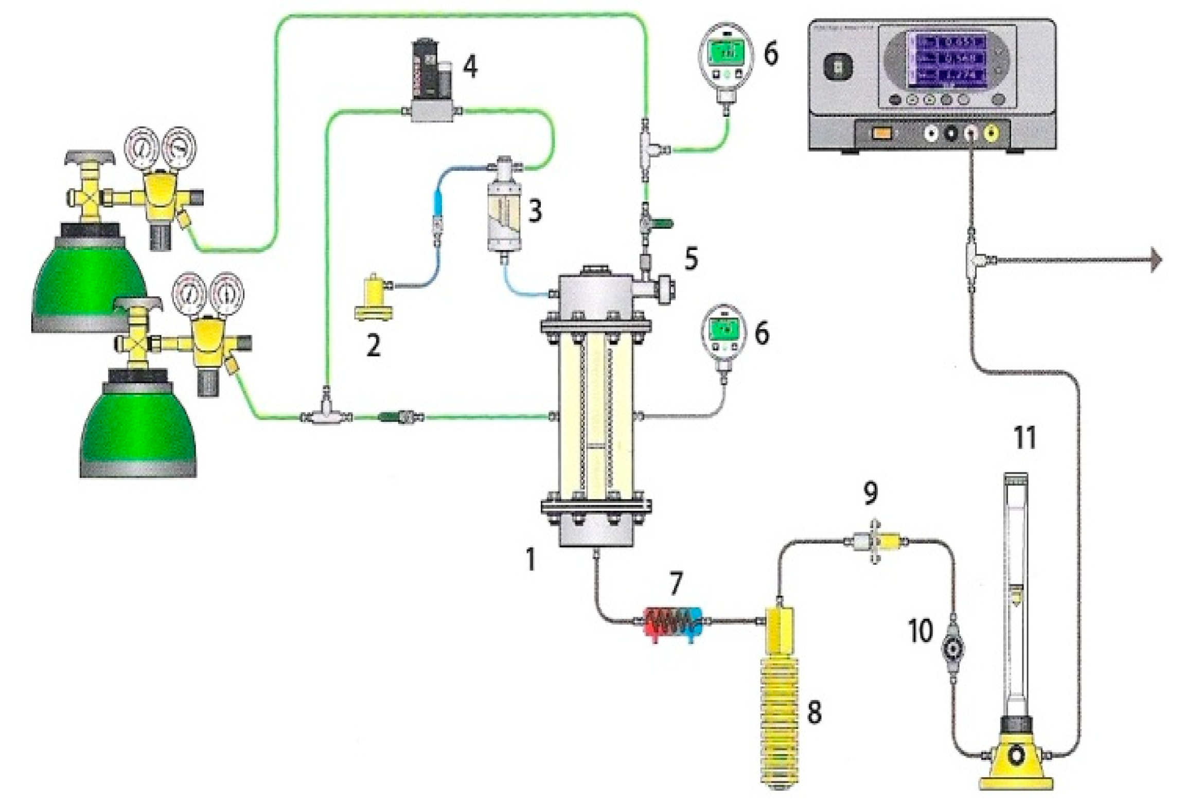
The gasification measurements were performed using thermovolumetric laboratory equipment presented in Figure 1, the detailed description of which is shown in [25].
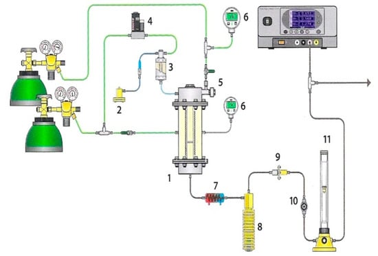
Figure 1.
Laboratory equipment for examinations of gasification process: (1) fixed-bed reactor, (2) water pump, (3) steam generator, (4) mass flow meter, (5) fuel feeder, (6) manometer, (7) cooler, (8) condensate tank, (9) filter, (10) pressure regulator, and (11) rotameter.
The equipment consists of three main systems, namely: (1) a high-pressure fixed-bed reactor with a heating system; (2) a system supplying gasifying medium (steam or CO2), carrier gas (argon or CO2), RDF sample to the reactor; and (3) a system for analysing the obtained gas. A quartz retort, diameter 20 mm, with a grate is placed inside the reactor. The retort is cased with steel, heat-resistant jacket, diameter 169 mm. The ends of the jacket are closed with lids fitted with pipes providing steam and argon* or carbon dioxide and pipes discharging the formed gas. The retort is heated using an electric oven, the insulation of which states mineral wool placed inside the casing. A thermocouple type K sensor measures the temperature of the RDF sample with an accuracy of 2 °C. Additionally, the sensor sends impulses to the controller-programmer, whose task is to maintain the required sample temperature. The sample of RDF fuel is introduced onto the retort grate with the use of a piston feeder. The movement of the piston is triggered by compression of gas inside the feeder chamber. The gas formed during the measurements flows into the condenser to separate tar and water, then is dried and cleaned on the filter and decompressed. After that, the concentrations of carbon monoxide, methane and carbon dioxide* are measured in a continuous way with the use of the Fuji Electric System gas analyser, based on the absorption of infrared radiation. Moreover, samples of gas are collected into syringes at specified time intervals in order to analyse the concentration of hydrogen with the use of the Clarus 580 gas chromatograph with a thermal conductivity detector (TCD) by Perkin Elmer.
The conditions under which the isothermal measurements were carried out are as follows: temperature: 700, 750, 800, 900 °C; pressure: 0.5, 1, 1.5 MPa; carrier gas flow: 2 dm3/min, steam flow: 0.3 g/min; RDF sample mass: 0.5 g. The temperature conditions were selected based on the authors’ previous experiences and a literature review [19,20,26]. When selecting the temperature, the critical guideline was to be in the kinetic region of the reaction, i.e., below 1000 °C, and due to the high reactivity of the selected fuel, the minimum temperature could be relatively low, i.e., 700 °C. In the case of pressures, there are no literature reports on analysing its impact on RDF gasification. However, research on gasification of other fuels indicates that total pressure increase may improve the gasification process, but at high pressures (>1 MPa), this positive effect diminishes. Each measurement was carried out at least twice to ensure repeatability of the results. In the above description, symbol (*) applies to gasification with steam.
The measurements of concentrations of the resulting gas components allowed to determine: (i) curves of changes in their formation rates over time; (ii) yields of gas components and quality of the resulting gas (H2/CO ratio and lower calorific value); as well as maximum carbon conversion degree achieved.
The curves of the formation rates of gaseous products over time were determined using Equation (1).
where: —time (min); —volumetric flow of the resulting gas (cm3/min); —concentration of the individual product in the resulting gas at time (vol.%).
The determined curves were used to calculate the yields of gasification products. The yields of products corresponded to the area under their kinetic curves and were calculated based on Equation (2) (Equation (2) is an adaptation of the algorithm of numerical integration using the trapezoidal method):
where: —volume of a given product (cm3); —concentration of a given product in time ; —concentration of a given product in time .
Finally, maximum carbon conversion degree was calculated using Equations (3) and (4) for gasification with steam and carbon dioxide, respectively:
where: —carbon conversion in time (%), —a volume of a given product formed from the beginning of the process to time t (cm3); —a molar mass of C element ; —a mass of the analysed coal sample (g); —dry and ash-free carbon content (-); —a molar volume of gas
3. Results and Discussion
3.1. Characteristic of RDF
The characteristic of alternative fuel used for the research, supplemented with reference values for this type of fuel, are summarised in Table 1. The analysed RDF has high carbon content, high HHV, and low moisture content compared to this type of fuel, proving a high degree of MSW processing. Moreover, volatile matter and ash contents are also high (within the upper limits of reference values), suggesting that the amount of char formed during gasification measurements (in the pyrolysis stage) will be low, and its quality may be inadequate. Interestingly, the analysed RDF has a very high hydrogen content, much higher than typical refuse-derived fuels. It may be related to a significant share of plastics in the analysed RDF sample [27]. Finally, the mercury content was determined since it is an essential environmental indicator as it is toxic and can accumulate in living organisms [28]. The Hg content in the analysed fuel is relatively low, equal to 899 μg/kg. Therefore, it can be concluded that the use of selected RDF as a fuel will be safe, especially that mercury from RDF gasification is emitted into the atmosphere mainly in the removable form of Hg(g)2+ (~60%) [29].

Table 1.
Characteristic of RDF.
The composition of ash from the analysed RDF is presented in Table 2. One can be observed that the share of calcium oxide, considered compounds that catalyse the gasification process [32], is the highest (above 40%). The ash also contains other catalytically active components (e.g., oxides of iron, potassium, magnesium and sodium [33,34]), but their shares are low. On the other hand, over 1/3 of the ash consists of compounds that have an adverse effect on gasification reaction, such as Al2O3, SiO2 or P2O5 [35,36]. Thus, the effect of ash on the RDF gasification process is difficult to predict.
Table 2.
Composition of RDF ash.
3.2. Gasification of RDF in Steam Atmosphere
3.2.1. Changes in the Formation Rates of Gaseous Components
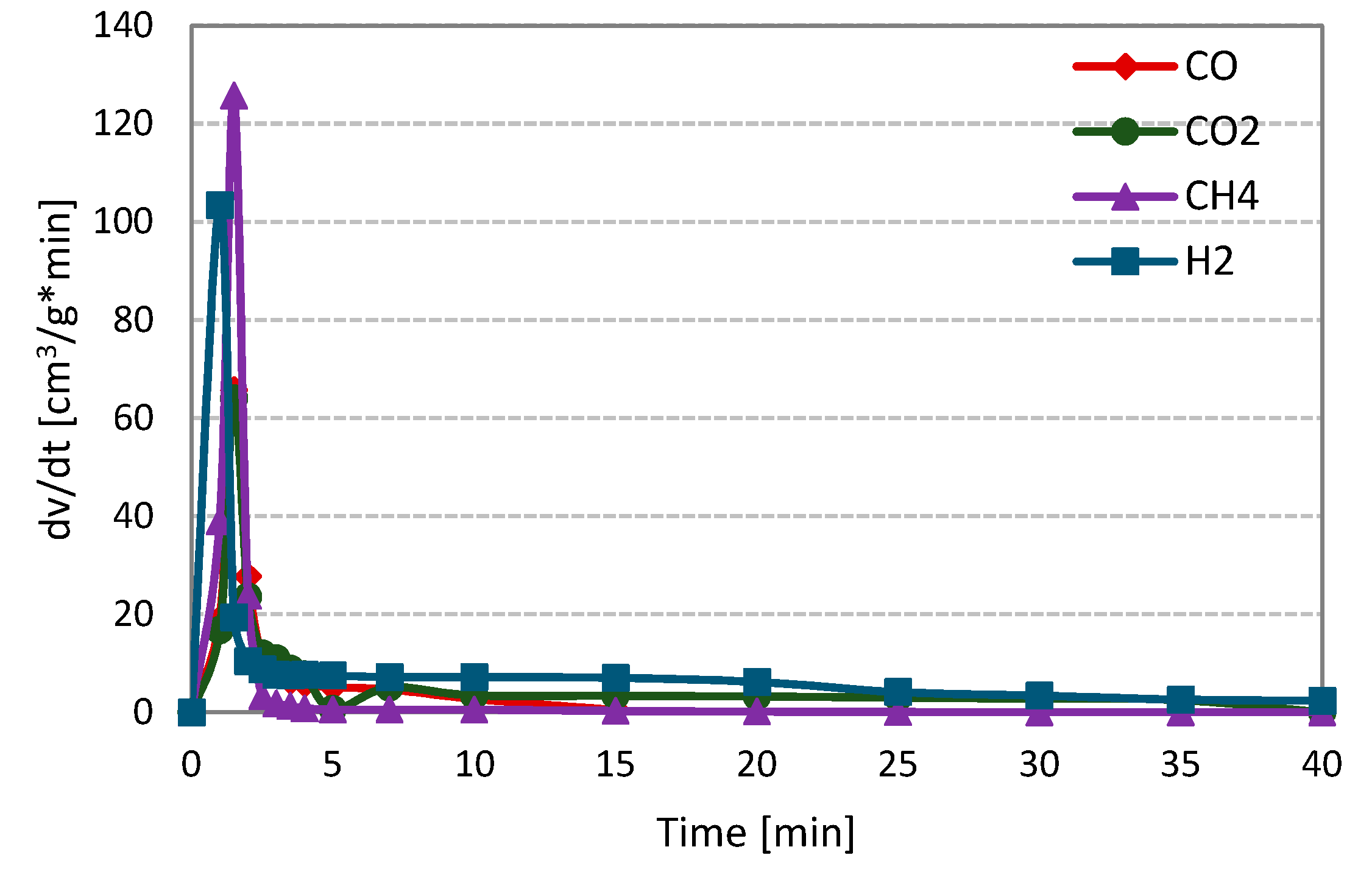
Figure 2 shows the changes in the formation rates of analysed gas components, i.e., carbon monoxide, hydrogen, carbon dioxide and methane, during steam gasification of RDF (on the example of measurement at 800 °C and 1 MPa).
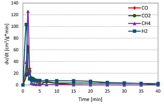
Figure 2.
Changes in the formation rates of gas components during steam gasification of RDF at 800 °C and 1 MPa.
At the initial stage of the RDF gasification, a dynamic increase in the formation rates of all gas components may be observed. This increase was related to the thermal decomposition of fuel, i.e., the pyrolysis process. During the pyrolysis stage, methane was characterised by the highest formation rate, followed by hydrogen and finally carbon monoxide and dioxide (formation rates of CO and CO2 were comparable). Then, a much slower and longer RDF-char gasification took place. At this stage, H2, CO and CO2 were formed, whereas methane was not observed. Moreover, the hydrogen formation rate was the highest, and this gas, along with carbon dioxide, was formed during the whole char gasification stage.
In contrast, the CO formation rate was the lowest, and the formation of this gas ends earlier than other components formed during the gasification stage. The character of the presented curves indicates that carbon-steam reaction (resulting in CO and H2) was accompanied by secondary reactions, e.g., the water-gas shift reaction (WGSR), in which carbon monoxide is converted into carbon dioxide and hydrogen. The curves obtained during gasification under different temperature-pressure conditions were similar to those in Figure 1. The evident domination of the pyrolysis stage during gasification measurements is related to the high volatile matter content in the analysed fuel.
3.2.2. Effect of Process Conditions on H2 and CO Formation Rates
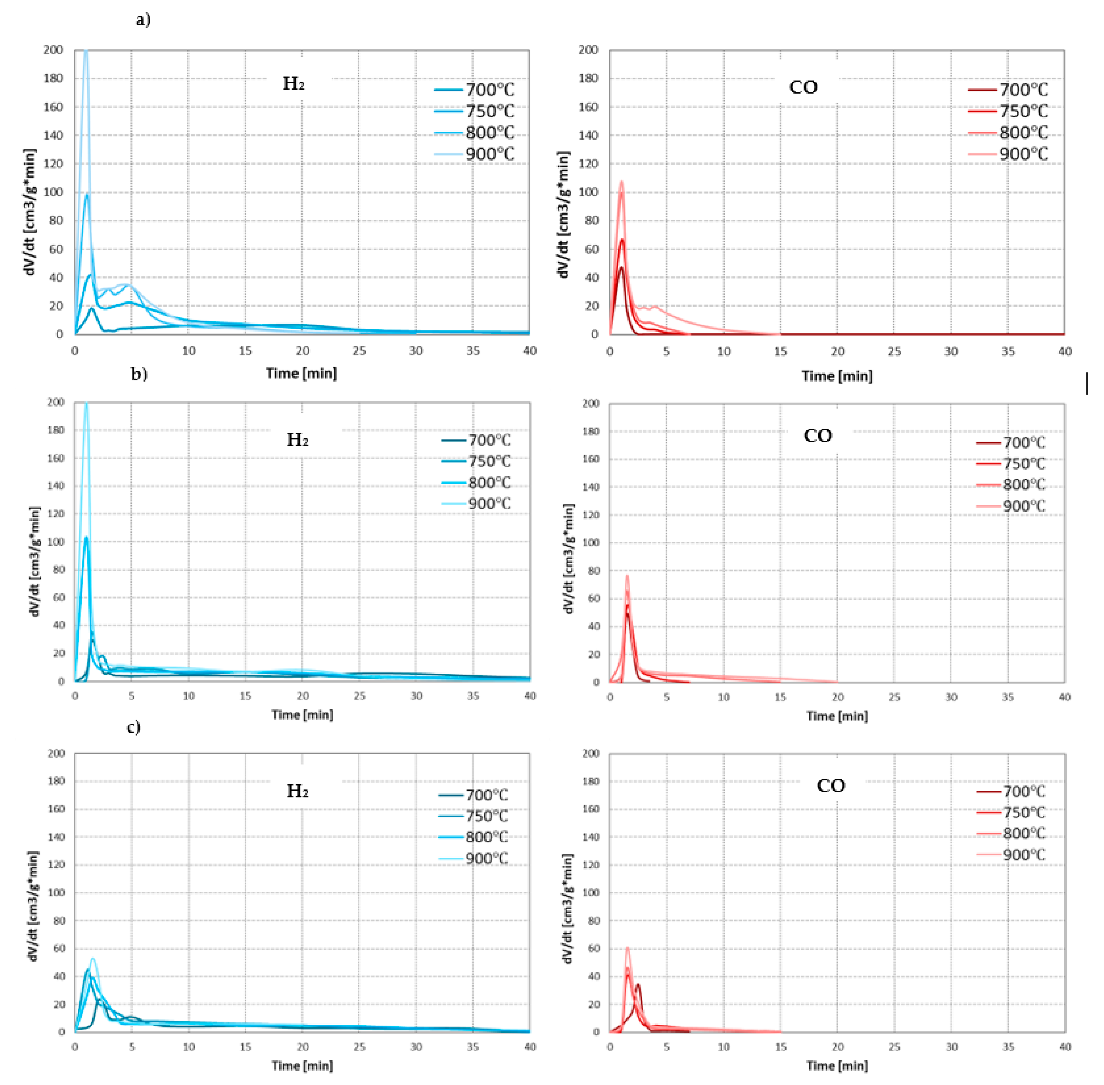
As the main components of the synthesis gas from the steam gasification are hydrogen and carbon monoxide, the effect of conditions on the process was assessed based on the formation rates of these gases. Figure 3 presents changes in the formation rates of H2 and CO during steam gasification of RDF at analysed temperatures and pressures.
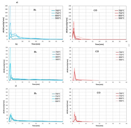
Figure 3.
Changes in the formation rates of H2 and CO during steam gasification of RDF at various temperatures and under: (a) 0.5 MPa; (b) 1 MPa; (c) 1.5 MPa.
In each case analysed, as the process temperature increased, the intensity of the pyrolysis stage increased significantly, resulting in higher H2 and CO formation rates. However, this positive effect of temperature decreased with increasing pressure. The effect of temperature on the char gasification stage was similar. At lower pressures (0.5 and 1 MPa), the increase in temperature generally increase formation rates of H2 and CO. Moreover, higher temperatures resulted in a prolonged time of carbon monoxide formation (at the lowest temperature of 700 °C, CO was formed only in the pyrolysis stage). This phenomenon may result from the low efficiency of the carbon-steam reaction at low temperatures (such as 700 °C) and the conversion of CO formed in this reaction into CO2 and H2 during exothermic WGSR. However, as in the case of the pyrolysis stage, also during the gasification stage, the positive effect of temperature on the formation rates of main gas components decreased with increasing pressure. As a result, it was almost invisible at the highest pressure of 1.5 MPa.
When analysing the effect of pressure, it can be seen that its increase negatively affects the steam gasification process. In most cases, higher pressures resulted in a decrease in rates of CO and H2 formation, both in the pyrolysis stage (especially in the case of H2 at high temperatures) and gasification stage (especially in the case of CO, which at the highest pressure of 1.5 MPa was practically not formed, even at high temperatures). The negative effect of pressure on the release of gaseous products during pyrolysis is confirmed in the literature [37,38]. It is also proved that high pressures favour higher char yields since they inhibit evaporation and thermal ejection of compounds from the liquid intermediate phase (compared to lower pressures) [39]. However, chars formed at high-pressure conditions are generally characterised by low reactivity due to increased uniformity of carbonaceous structure [40]. This phenomenon may explain a decrease in the formation rates of gas components with increasing process pressure during char gasification. Moreover, an increase in pressure changed the formation rate of CO and H2 in line with the predictions of Le Chatelier’s principle.
3.2.3. Effect of Process Conditions on the Resulting Gas
The yields of the gas components obtained during steam gasification of the analysed RDF under various conditions are shown in Figure 4.
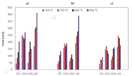
Figure 4.
Yields of gas components formed during steam gasification of RDF at various temperatures and under: (a) 0.5 MPa; (b) 1 MPa; (c) 1.5 MPa.
Based on Figure 4, general conclusions can be drawn that hydrogen is the dominant product of the steam gasification of RDF, followed by carbon dioxide. The highest yields of these gases indicate the importance of secondary reactions. Methane, being a product of the pyrolysis stage, was in most cases the third most yielded gas component (although at high temperatures and 1.5 MPa, its yields were greater than CO2), while carbon monoxide was usually characterised by the lowest yields.
As the temperature rises, the yield of carbon monoxide increases, which results from the endothermic nature of the carbon-steam reaction; however, this increase diminishes at higher pressures. In the case of hydrogen, the dependencies are analogous as for CO, although, at the highest pressure, even a drop in H2 yield was observed above 750 °C. This discrepancy may be because hydrogen was formed in various reactions, including the exothermic WGSR, the efficiency of which may be adversely affected by high pressure [41]. In most cases, also methane yield increase with temperature, which results from increased pyrolysis intensity at high temperatures. In turn, no unequivocal effect of temperature on CO2 yield was observed.
When analysing the effect of pressure, it can be seen that it negatively impacts the yields of most gas components, i.e., CO and H2 (especially at high temperatures) and CO2. The only gas component that was positively influenced by an increase in pressure was methane (the highest yields of CH4 were observed at the highest pressure). It is probably due to the changes in secondary pyrolysis reactions, namely by favouring auto-hydrogenation reactions at high pressures [42].
To assess the quality of the gas obtained under various conditions, the H2/CO ratio and lower heating values were presented in Table 3.
Table 3.
The H2/CO ratio and LHV of gas from steam gasification of RDF.
The resulting gas was characterised by a high H2/CO ratio—in most measurements, this value exceeded 3. The increase in temperature generally decreased this ratio, while an increase in pressure had the opposite effect. In turn, the LHV of the resulting gas ranges from 8.2 to 16.2 MJ/Nm3, and with an increase in temperature, this value generally increases. On the other hand, the effect of pressure was ambiguous. However, gas obtained during gasification at the highest pressure (1.5 MPa) was characterised by the highest LHV, which results from the high percentage share of methane in this gas.
3.2.4. Effect of Process Conditions on Maximum Carbon Conversion Degree
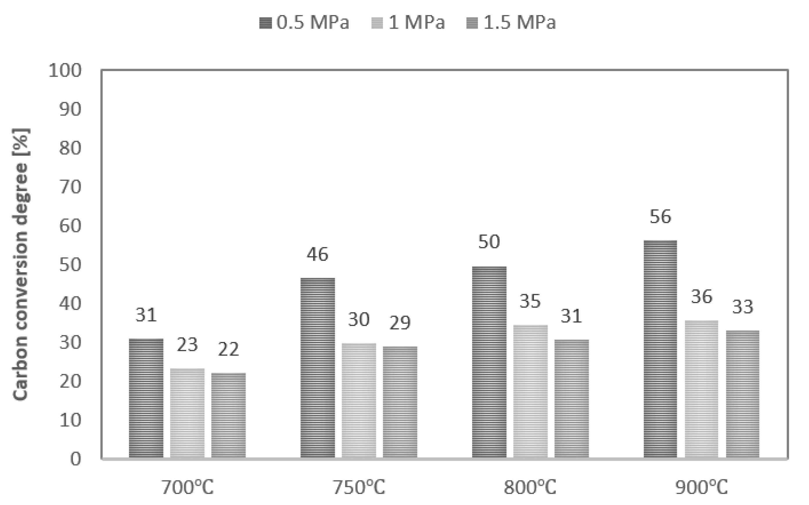
Values of maximum carbon conversion degree achieved during steam gasification of analysed RDF at various conditions are shown in Figure 5. Along with the increase in process temperature, the values of the maximum conversion degree also increase, while the increase in pressure decreases these values. As a result, the maximum carbon conversion degree ranged between 22% (T—700 °C, p—1.5 MPa) and 56% (T—900 °C, p—0.5 MPa). In addition, along with an increase in pressure, the effect of temperature on the carbon conversion degree decreased. However, it should be noted that the maximum conversion degrees achieved were low, regardless of process conditions. This phenomenon is probably due to the high plastics content in the feedstock and the high intensity of the pyrolysis stage, which favour the formation of liquid products during the process [27].
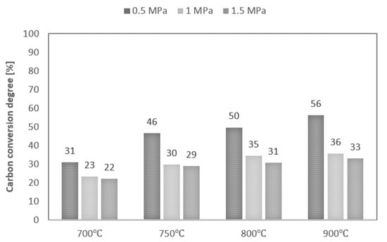
Figure 5.
Values of maximum carbon conversion degree during steam gasification of RDF at various temperatures and pressures.
3.3. Gasification of RDF in Carbon Dioxide Atmosphere
3.3.1. Changes in the Formation Rates of Gaseous Components
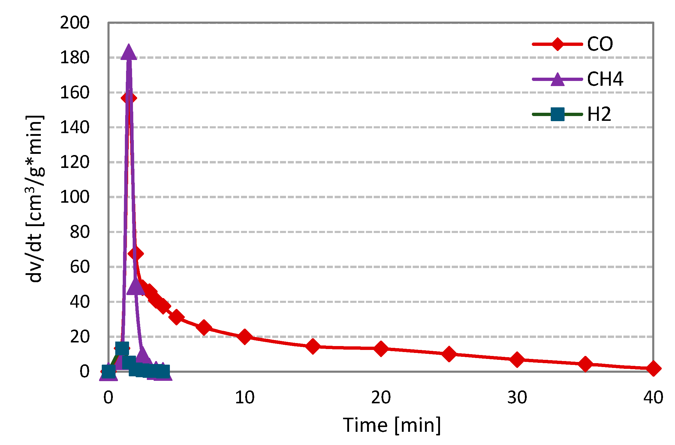
Figure 6 shows the changes in the formation rates of analysed gas components, i.e., carbon monoxide, hydrogen and methane, during CO2 gasification of RDF (on the example of measurement at 800 °C and 1 MPa).
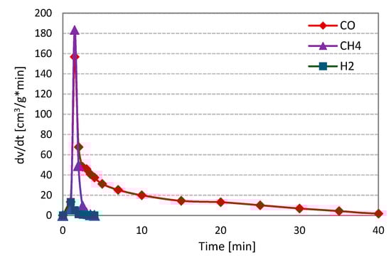
Figure 6.
Changes in the formation rates of gas components during CO2 gasification of RDF at 800 °C and 1 MPa.
As in the case of gasification with steam, violent pyrolysis took place in the first minutes of the measurements. During this stage, methane was characterised by the highest release rate, followed by carbon monoxide and hydrogen (the formation rate of H2 was minimal). After completion of thermal decomposition, the only component of the analysed gas was carbon monoxide—the product of the Boudouard RDF char-CO2 reaction. The curves obtained during gasification under different temperature-pressure conditions were similar to those in Figure 6.
3.3.2. Effect of Process Conditions on the CO Formation Rates
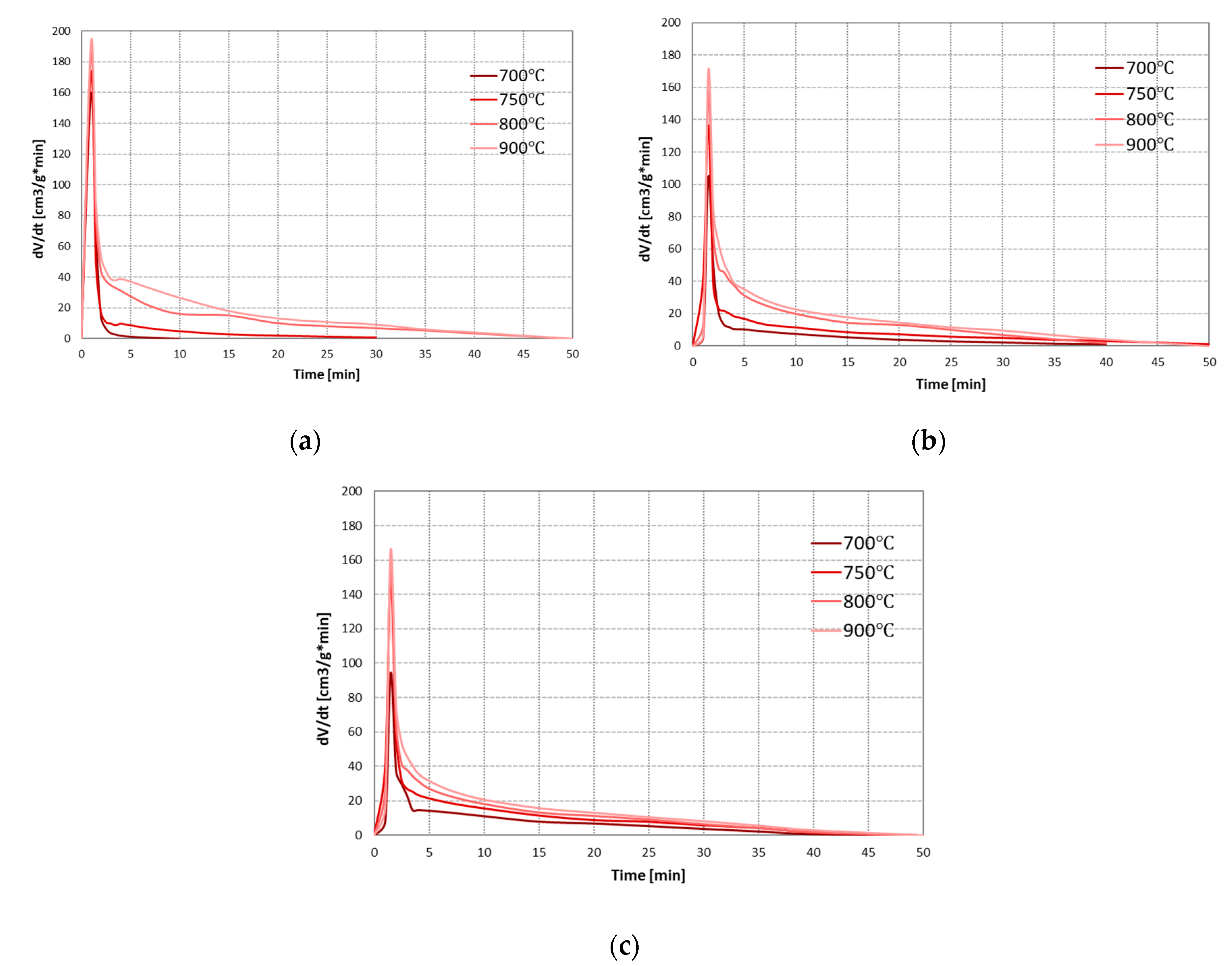
As the main component of carbon dioxide gasification is carbon monoxide, the effect of conditions on the process was assessed based on the formation rates of this gas. Figure 7 presents the changes in the formation rates of CO during CO2 gasification of RDF at analysed temperatures and pressures.
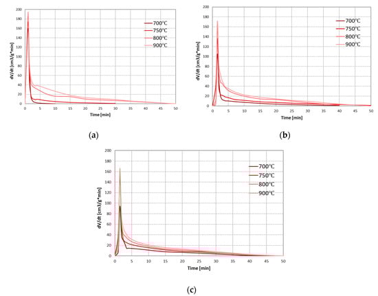
Figure 7.
Changes in the formation rates of CO during CO2 gasification of RDF at various temperatures and under: (a) 0.5 MPa; (b) 1 MPa; (c) 1.5 MPa.
As the process temperature increases, an increase in the carbon monoxide formation rate was observed during the entire process, i.e., both pyrolysis and gasification stages. It is related to the highly endothermic nature of the Boudouard reaction. Moreover, as in the case of steam gasification, an increase in temperature extended the char gasification stage (which at low temperatures and pressure of 0.5 MPa did not occur). On the other hand, the effect of pressure is more complex—with increasing pressure, the maximum formation rates of CO in the pyrolysis stage decreased, whereas in the gasification stage increased, but only at low temperatures (700–750 °C). These results indicate that at low temperatures (in which the gasification stage was not efficient), the increase in pressure improved the CO2 gasification reaction. This phenomenon is possibly related to an increased concentration of active sites [43]. However, at higher process temperatures, the positive effect of pressure was not observed.
3.3.3. Effect of Process Conditions on the Resulting Gas
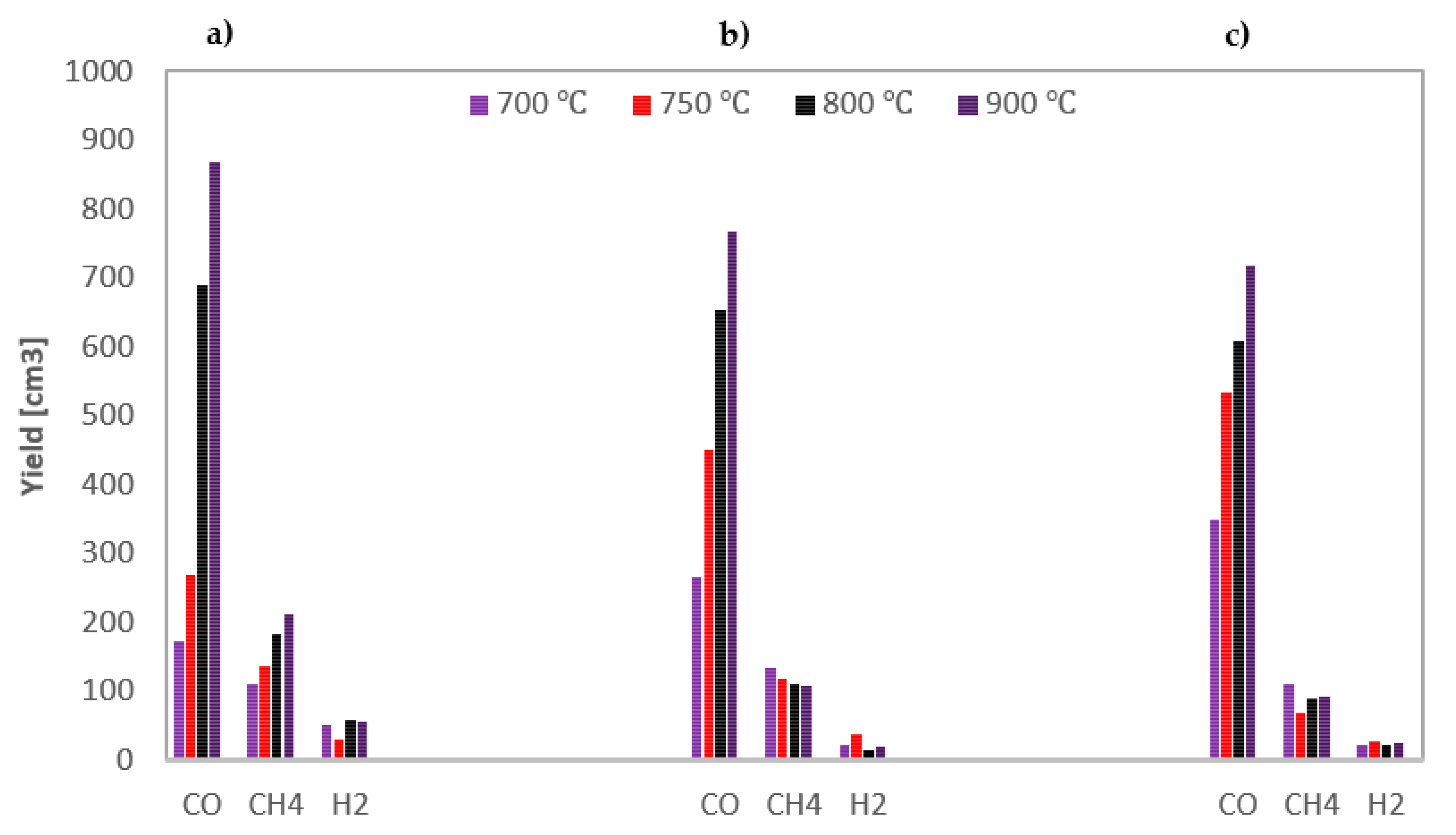
The yields of the gas components obtained during CO2 gasification of the analysed RDF under various conditions are shown in Figure 8.
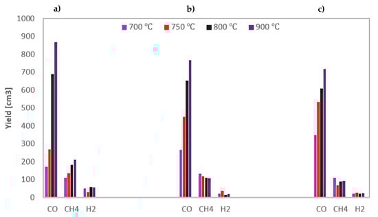
Figure 8.
Yields of gas components formed during CO2 gasification of RDF at various temperatures and under: (a) 0.5 MPa; (b) 1 MPa; (c) 1.5 MPa.
The results from Figure 8 confirm the conclusion drawn from the curves of CO formation rates. The main component of the resulting gas was carbon monoxide, the yields of which increased due to an increase in temperature. In turn, an increase in pressure had a positive effect on CO yields only at low temperatures of 700–750 °C, wherein the greater the pressure increase, the lower the positive effect was. The second most-yielded gas component was methane, and finally hydrogen (the yields of which was minimal). Both these gases were released only during the pyrolysis stage, and there was no unequivocal effect of process conditions on their quantity.
In order to assess the quality of the gas obtained under various process conditions, the lower heating values were presented in Table 4. The H2/CO ratio was omitted due to the minimal content of hydrogen in the resulting gas.
Table 4.
The LHV of gas from CO2 gasification of RDF.
The LHV of the resulting gas was high—it ranges from 15.3 to 19.9 MJ/Nm3, and the influence of the process conditions on this parameter was unequivocal. Along with an increase in both temperature and pressure, the LHV decreased. This decrease was related to the decreasing percentage share of high calorific methane in the resulting gas, along with an increase in temperature and pressure.
3.3.4. Effect of Process Conditions on Maximum Carbon Conversion Degree
Values of maximum carbon conversion degree achieved during CO2 gasification of analysed RDF at various conditions are shown in Figure 9.
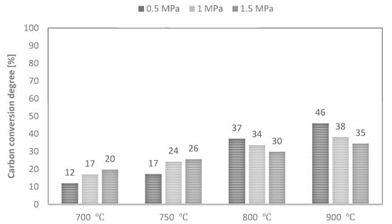
Figure 9.
Values of maximum carbon conversion degree during CO2 gasification of RDF at various temperatures and pressures.
As CO was the dominant gas component of the analysed process, the yield of this gas determined the carbon conversion degree achieved. Therefore, along with an increase in process temperature, the values of the maximum conversion degree also increased. In turn, an increase in pressure increased these values at 700–750 °C and decreased at higher temperatures of 800–900 °C. As a result, the maximum achieved conversion degree ranged between 12% (T—700 °C, p—0.5 MPa) and 46% (T—900 °C, p—0.5 MPa). Since the same RDF was subjected to CO2 and steam gasification process, the maximum carbon conversion degrees were also low in this case.
4. Conclusions
Based on the performed measurements, the effect of temperature-pressure conditions on RDF gasification in steam and carbon dioxide was assessed. The vast majority of literature research on gasification process is based on the ex situ method, i.e., previously prepared and cooled char is then used in the measurements. Therefore, to better reflect the process of fuel gasification occurring in the commercial gasifiers, a new approach was used, i.e., samples of fuel rather than its char were subjected to gasification measurements. Moreover, the use of unique equipment (developed by the authors) based on the thermovolumetric method enables a much more reliable process analysis than the widely used thermogravimetric method since it includes an analysis of sample reactivity and the quality and quantity of the resulting gas.
In turn, to the best of the authors’ knowledge, the effect of high pressure on RDF gasification has not been the subject of published studies so far. The results obtained during the examinations also enable a preliminary assessment of RDF for the process of gasification and can be used to model the process. The RDF selected for research was characterised by especially high volatile matter, ash, and hydrogen contents compared to reference refuse-derived fuels. The gasification measurements proved that increase in temperature from 700 to 900 °C has a positive effect on the process. During measurements, the formation rates of main gas components (CO and H2 in steam gasification and CO in carbon dioxide gasification) increased. Moreover, yields of these gases and maximum carbon conversion degrees were improved. However, when this positive effect of temperature was lower, the higher the pressure was.
On the other hand, the increase in pressure from 0.5 MPa to 1.5 MPa generally had an adverse effect on the gasification process, regardless of the gasifying agent used. In most cases, higher pressure caused deterioration of the analysed parameters. The exceptions were the measurements at low temperatures (700–750 °C) in the atmosphere of carbon dioxide (when an increase in pressure resulted in higher CO formation rates during RDF-char gasification stage as well as an increase in yields of CO and maximum conversion degree achieved). The results obtained during the examinations enable a preliminary assessment of RDF for the process of gasification.
Author Contributions
Conceptualization, K.Ś.; methodology, K.Ś.; validation, K.Ś.; formal analysis, K.Ś.; investigation, K.B. and K.Ś.; resources, K.Ś. and G.C.; data curation, K.Ś.; writing—original draft preparation, K.B. and K.Ś.; writing—review and editing, K.Ś. and G.C.; visualization, K.Ś.; supervision, G.C. All authors have read and agreed to the published version of the manuscript.
Funding
This research was funded by Research Subsidy of the AGH University of Science and Technology for the Faculty of Energy and Fuels (No. 16.16.210.476).
Institutional Review Board Statement
Not applicable.
Informed Consent Statement
Not applicable.
Data Availability Statement
The data that support the findings of this study are available from the corresponding author upon reasonable request.
Conflicts of Interest
The authors declare no conflict of interest.
References
- Karak, T.; Bhagat, R.M.; Bhattacharyya, P. Municipal Solid Waste Generation, Composition, and Management: The World Scenario. Crit. Rev. Environ. Sci. Technol. 2012, 42, 1509–1630. [Google Scholar] [CrossRef]
- Yang, Y.; Liew, R.K.; Tamothran, A.M.; Foong, S.Y.; Yek, P.N.Y.; Chia, P.W.; Van Tran, T.; Peng, W.; Lam, S.S. Gasification of refuse-derived fuel from municipal solid waste for energy production: A review. Environ. Chem. Lett. 2021, 19, 2127–2140. [Google Scholar] [CrossRef] [PubMed]
- Statistica. Projected Generation of Municipal Solid Waste Worldwide from 2016 to 2050. 2020. Available online: https://www.statista.com/statistics/916625/global-generation-of-municipal-solid-waste-forecast (accessed on 2 October 2020).
- Białowiec, A. Hazardous emissions from municipal solid waste landfills. Contemp. Probl. Manag. Environ. Ment. Prot. 2011, 9, 7–28. [Google Scholar]
- Funk, K.; Milford, J.; Simpkins, T. Waste Not, Want Not: Analyzing the Economic and Environmental Viability of Waste-to-Energy (WTE) Technology for Site-Specific Optimization of Renewable Energy Options; NREL/TP-6A50-52829; NREL: Golden, CO, USA, 2013. [Google Scholar]
- Martínez, I.; Grasa, G.; Callén, M.S.; López, J.M.; Murillo, R. Optimised production of tailored syngas from municipal solid waste (MSW) by sorption-enhanced gasification. Chem. Eng. J. 2020, 401, 126067. [Google Scholar] [CrossRef]
- Lam, S.S.; Liew, R.K.; Jusoh, A.; Chong, C.T.; Ani, F.N.; Chase, H.A. Progress in waste oil to sustainable energy, with emphasis on pyrolysis techniques. Renew. Sustain. Energy Rev. 2016, 53, 741–753. [Google Scholar] [CrossRef]
- Foong, S.Y.; Chan, Y.H.; Cheah, W.Y.; Kamaludin, N.H.; Ibrahim, T.; Sonne, C.; Peng, W.; Show, P.-L.; Lam, S.S. Progress in waste valorization using advanced pyrolysis techniques for hydrogen and gaseous fuel production. Bioresour. Technol. 2021, 320, 124299. [Google Scholar] [CrossRef]
- Mondal, P.; Dang, G.; Garg, M. Syngas production through gasification and cleanup for downstream applications—Recent developments. Fuel Process. Technol. 2011, 92, 1395–1410. [Google Scholar] [CrossRef]
- Grazhdani, D. Assessing the variables affecting on the rate of solid waste generation and recycling: An empirical analysis in Prespa Park. Waste Manag. 2016, 48, 3–13. [Google Scholar] [CrossRef]
- Noufal, M.; Yuanyuan, L.; Maalla, Z.; Adipah, S. Determinants of Household Solid Waste Generation and Composition in Homs City, Syria. J. Environ. Public Health 2020, 2020, 7460356. [Google Scholar] [CrossRef]
- Sharma, K.D.; Jain, S. Municipal solid waste generation, composition, and management: The global scenario. Soc. Responsib. J. 2020, 16, 917–948. [Google Scholar] [CrossRef]
- Seo, Y.-C.; Alam, T.; Yang, W.-S. Gasification of Municipal Solid Waste. In Gasification for Low-Grade Feedstock; IntechOpen: London, UK, 2018. [Google Scholar] [CrossRef] [Green Version]
- Pawłowski, P.; Bałazińska, M.; Ignasiak, K.; Robak, J. Przygotowanie odpadów komunalnych do ich energetycznego wykorzystania: Paliwo typu SRF. Piece Przemysłowe Kotły 2016, 4, 20–26. [Google Scholar]
- Caputo, A.C.; Pelagagge, P.M. RDF production plants: Design and costs. Appl. Therm. Eng. 2002, 22, 423–437. [Google Scholar] [CrossRef]
- Achinas, S.; Kapetanios, E. Efficiency Evaluation of RDF Plasma Gasification Process. Energy Environ. Res. 2013, 3, 150–157. [Google Scholar] [CrossRef] [Green Version]
- Corella, J.; Toledo, J.M.; Molina, G. Performance of CaO and MgO for the hot gas clean up in gasification of a chlorine-containing (RDF) feedstock. Bioresour. Technol. 2008, 99, 7539–7544. [Google Scholar] [CrossRef] [PubMed]
- Galvagno, S.; Casu, S.; Casciaro, G.; Martino, M.; Russo, A.A.; Portofino, S. Steam Gasification of Refuse-Derived Fuel (RDF): Influence of Process Temperature on Yield and Product Composition. Energy Fuels 2006, 20, 2284–2288. [Google Scholar] [CrossRef]
- van Kasteren, J.M. Co-gasification of wood and polyethylene with the aim of CO and H2 production. J. Mater. Cycles Waste Manag. 2006, 8, 95–98. [Google Scholar] [CrossRef]
- Dalai, A.K.; Batta, N.; Eswaramoorthi, I.; Schoenau, G.J. Gasification of refuse derived fuel in a fixed bed reactor for syngas production. Waste Manag. 2009, 29, 252–258. [Google Scholar] [CrossRef]
- Rashidi, M.; Tavasoli, A. Hydrogen rich gas production via supercritical water gasification of sugarcane bagasse using unpromoted and copper promoted Ni/CNT nanocatalysts. J. Supercrit. Fluids 2015, 98, 111–118. [Google Scholar] [CrossRef]
- Safari, F.; Salimi, M.; Tavasoli, A.; Ataei, A. Non-catalytic conversion of wheat straw, walnut shell and almond shell into hydrogen rich gas in supercritical water media. Chin. J. Chem. Eng. 2016, 24, 1097–1103. [Google Scholar] [CrossRef]
- Zubek, K.; Czerski, G.; Porada, S. Comparison of Catalysts Based on Individual Alkali and Alkaline Earth Metals with Their Composites Used for Steam Gasification of Coal. Energy Fuels 2017, 32, 5684–5692. [Google Scholar] [CrossRef]
- Czerski, G.; Zubek, K.; Grzywacz, P.; Porada, S. Effect of Char Preparation Conditions on Gasification in a Carbon Dioxide Atmosphere. Energy Fuels 2018, 31, 815–823. [Google Scholar] [CrossRef]
- Śpiewak, K.; Czerski, G.; Porada, S. Effect of K, Na and Ca-based catalysts on the steam gasification reactions of coal. Part I: Type and amount of one-component catalysts. Chem. Eng. Sci. 2021, 229, 116024. [Google Scholar] [CrossRef]
- Czerski, G.; Śpiewak, K.; Grzywacz, P.; Wierońska-Wiśniewska, F. Assessment of the catalytic effect of various biomass ashes on CO2 gasification of tire char. J. Energy Inst. 2021, 99, 170–177. [Google Scholar] [CrossRef]
- Jin, Q.; Wang, X.; Li, S.; Mikulčić, H.; Bešenić, T.; Deng, S.; Vujanović, M.; Tan, H.; Kumfer, B. Synergistic effects during co-pyrolysis of biomass and plastic: Gas, tar, soot, char products and thermogravimetric study. J. Energy Inst. 2019, 92, 108–117. [Google Scholar] [CrossRef]
- Dziok, T.; Bury, M.; Bytnar, K.; Burmistrz, P. Possibility of using alternative fuels in Polish power plants in the context of mercury emissions. Waste Manag. 2021, 126, 578–584. [Google Scholar] [CrossRef] [PubMed]
- Lonati, G.; Zanoni, F. Monte-Carlo human health risk assessment of mercury emissions from a MSW gasification plant. Waste Manag. 2013, 33, 347–355. [Google Scholar] [CrossRef]
- Haydary, J.; Šuhaj, P.; Šoral, M. Semi-Batch Gasification of Refuse-Derived Fuel (RDF). Processes 2021, 9, 343. [Google Scholar] [CrossRef]
- Kara, M.; Günay, E.; Tabak, Y.; Yıldız, Ş. Perspectives for pilot scale study of RDF in Istanbul, Turkey. Waste Manag. 2009, 29, 2976–2982. [Google Scholar] [CrossRef]
- Coetzee, S.; Neomagus, H.; Bunt, J.; Everson, R.C. Improved reactivity of large coal particles by K2CO3 addition during steam gasification. Fuel Process. Technol. 2013, 114, 75–80. [Google Scholar] [CrossRef]
- Śpiewak, K.; Czerski, G.; Sopata, A. Examination of steam gasification of coal with physically mixed catalysts. Pol. J. Chem. Technol. 2019, 21, 51–57. [Google Scholar] [CrossRef] [Green Version]
- Huang, X.; Zhang, F.; Fan, M.; Wang, Y. Catalytic Coal Gasification. In Sustainable Catalytic Processes; Elsevier: London, UK, 2015; pp. 179–199. [Google Scholar]
- Dupont, C.; Jacob, S.; Marrakchy, K.O.; Hognon, C.; Grateau, M.; Labalette, F.; Perez, D.D.S. How inorganic elements of biomass influence char steam gasification kinetics. Energy 2016, 109, 430–435. [Google Scholar] [CrossRef]
- Yip, K.; Tian, F.; Hayashi, J.-I.; Wu, H. Effect of Alkali and Alkaline Earth Metallic Species on Biochar Reactivity and Syngas Compositions during Steam Gasification. Energy Fuels 2010, 24, 173–181. [Google Scholar] [CrossRef]
- Pecha, M.B.; Terrell, E.; Montoya, J.I.; Stankovikj, F.; Broadbelt, L.J.; Chejne, F.; Garcia-Perez, M. Effect of Pressure on Pyrolysis of Milled Wood Lignin and Acid-Washed Hybrid Poplar Wood. Ind. Eng. Chem. Res. 2017, 56, 9079–9089. [Google Scholar] [CrossRef]
- Noumi, E.S.; Blin, J.; Valette, J.; Rousset, P. Combined Effect of Pyrolysis Pressure and Temperature on the Yield and CO2 Gasification Reactivity of Acacia Wood in macro-TG. Energy Fuels 2015, 29, 7301–7308. [Google Scholar] [CrossRef]
- Pecha, M.B.; Arbelaez, J.I.M.; Garcia-Perez, M.; Chejne, F.; Ciesielski, P.N. Progress in understanding the four dominant intra-particle phenomena of lignocellulose pyrolysis: Chemical reactions, heat transfer, mass transfer, and phase change. Green Chem. 2019, 21, 2868–2898. [Google Scholar] [CrossRef] [Green Version]
- Cetin, E.; Moghtaderi, B.; Gupta, R.; Wall, T. Influence of pyrolysis conditions on the structure and gasification reactivity of biomass chars. Fuel 2004, 83, 2139–2150. [Google Scholar] [CrossRef]
- Byron, S.R.J.; Loganathan, M.; Shantha, M.S. A Review of the Water Gas Shift Reaction Kinetics. Int. J. Chem. React. Eng. 2010, 8, 1–32. [Google Scholar] [CrossRef]
- Mazumdar, B.K.; Chatterjee, N.N. Mechanism of coal pyrolysis in relation to industrial practice. Fuel 1973, 52, 11–19. [Google Scholar] [CrossRef]
- Roberts, D.G.; Harris, D.J. Char Gasification with O2, CO2, and H2O: Effects of Pressure on Intrinsic Reaction Kinetics. Energy Fuels 2000, 14, 483–489. [Google Scholar] [CrossRef]


Publisher’s Note: MDPI stays neutral with regard to jurisdictional claims in published maps and institutional affiliations. |
© 2021 by the authors. Licensee MDPI, Basel, Switzerland. This article is an open access article distributed under the terms and conditions of the Creative Commons Attribution (CC BY) license (https://creativecommons.org/licenses/by/4.0/).