Article

Effects of Front Plate Geometry on Brush Seal in Highly Swirling Environments of Gas Turbine

1
Marine Engineering College, Dalian Maritime University, Dalian 116026, China
2
Naval Architecture and Ocean Engineering College, Dalian Maritime University, Dalian 116026, China
*
Author to whom correspondence should be addressed.
Energies 2021, 14(22), 7768; https://doi.org/10.3390/en14227768
Submission received: 11 October 2021 / Revised: 11 November 2021 / Accepted: 12 November 2021 / Published: 19 November 2021
(This article belongs to the Special Issue Advanced Technologies in Gas Turbines)

Abstract

:
Advanced brush seal technology has a significant impact on the performance and efficiency of gas turbine engines. However, in highly inlet swirling environments, the bristles of a brush seal tend to circumferentially slip, which may lead to aerodynamic instability and seal failure. In this paper, seven different front plate geometries were proposed to reduce the impact of high inlet swirl on the bristle pack, and a three-dimensional porous medium model was carried out to simulate the brush seal flow characteristics. Comparisons of a plane front plate with a relief cavity, plane front plate with axial drilled holes, anti-“L”-type plate and their relative improved configurations on the pressure and flow fields as well as the leakage behavior were conducted. The results show that the holed front plate can effectively regulate and control the upstream flow pattern of the bristle pack, inducing the swirl flow to move radially inward, which results in decreased circumferential velocity component. The anti-“L” plate with both axial holes and one radial hole was observed to have the best effect on reducing the swirl of those investigated. The swirl velocity upstream the bristle pack can decline 50% compared to the baseline model with plane front plate, and the circumferential aerodynamic forces on the bristles, which scale with the swirl dynamic head, are reduced by a factor of 4. This could increase the bristle stability dramatically. Moreover, the front plate geometry does not influence the leakage performance significantly, and the application of the axial hole on the front plate will increase the leakage slightly by around 3.5%.

1. Introduction

Brush seal are used in the sealing field with high-speed rotating shafts, such as aero engines and gas turbine engines. As a substitute for the traditional labyrinth seal, it has shown great sealing performance by reducing the leakage rate to 80–90% times that of the latter [1,2,3]. The typical brush seal structure includes front plate, bristle pack and backing ring plate, as shown in Figure 1. In order to reduce the wearing between the bristles and the rotor and make it easier for the bristles to adapt to the radial movement of the rotor, the bristles are inclined at 30–60° in the circumferential direction of rotor rotation. After the airflow enters into the bristle pack, the reverse flow, transverse flow, jet and swirl flow will occur in the bristle pack. The flow resistance caused by the bristles will dissipate a large amount of energy and thereby achieve a good sealing performance.
The mechanical behavior of the brush seal, under the influences of aerodynamic load, reaction force and friction between bristles and rotor, bristles and backing plate and within bristle pack, is quite complicated. Basu et al. [4] experimentally verified that the contact force between the bristles and rotor would increase after being exposed to the airflow, which causes the adverse bristle stiffness and reduces the service life of the brush seal. Stango et al. [5] and Zhao et al. [6,7] analyzed the contact force model between the bristle–rotor under different interferences in a two-dimensional plane and analyzed the effect of the bristles’ geometric parameters on the contact force. Sun [8] investigated the bristle deflections and mechanical behavior based on the fluid–structure interaction model and conducted the experimental validation. In order to simplify the structure of the bristle pack, the porous medium model with appropriate porosity has become a broadly used mathematical method. Chew et al. [9] proposed a non-linear porous medium model for the continuity and momentum equations and calibrated the viscous and inertial coefficients with tested data. Based on this, they proposed an explanation for the bristle flutter and fatigue phenomenon [10]. Li [11] carried out a detailed analysis for the influence of radial clearance, bristle pack width, pressure ratio across the seal and the rotational speed on the leakage characteristics by non-linear porous medium model.
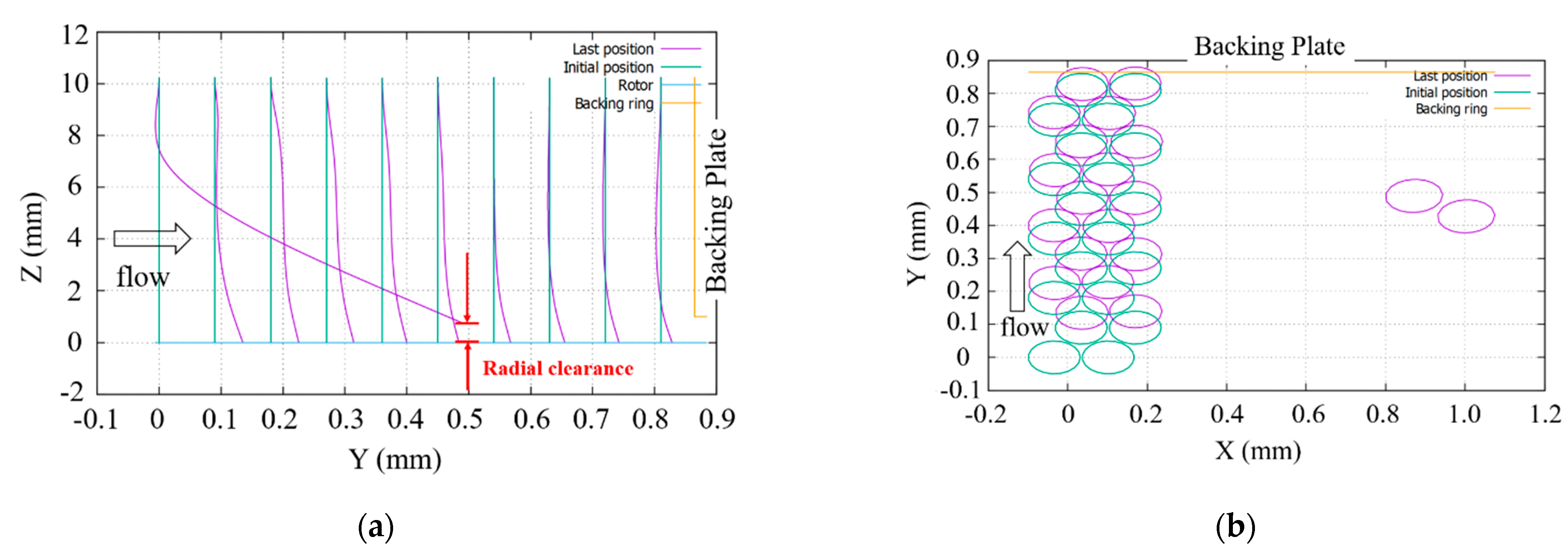
In recent years, researchers have paid more attention to the bristle deformation in the more realistic highly swirling environments and the consequent tip circumferential slip and instability. Sharatchandra et al. [12] and Helm et al. [13] found that the brush seals could weaken the swirling flow, which can benefit shaft dynamic stability [14]. However, lift forces are generated on the bristles under high swirling conditions, and this could cause instability of the upstream bristles and a deterioration in performance. Outirba et al. [15] conducted experiments on bearing chamber brush seals with rotor speeds 0~18,000 rpm. When the rotor reached 4000 rpm (17 m/s), the leakage flow was observed to increase due to the bristle slip caused by centrifugal force and large oil viscosity. Aksit et al. [16] also investigated bearing chamber brush seals. They reported that reduced tip pressure loads and interference could cause aerodynamic instability. Considering possible aerodynamic instability and seal failure, Liu et al. [17] and Kong et al. [18] analyzed the effect of inlet swirl on the bristle deflection using a coupled 3D CFD and mechanical model and demonstrated that when the velocity of inlet swirl increased to a certain critical value, the aerodynamic force would cause the upstream bristle rows to slip circumferentially. Figure 2 shows the bristles slip at a swirl velocity of 250 m/s, where X, Y and Z represented the circumferential, axial and radial direction, respectively. It was indicated that the upstream front plate design could reduce the swirl of flow impacting on the bristles, thereby improving the stability of the seal.
As for the front plate studies, Chi [19] analyzed the front plate’s effect on a low-hysteresis brush seal using a porous medium model. Dogu [20,21,22] presented the influence of the front plate structure, operating conditions and brush seal geometry on the leakage performance based on their improved porous CFD method. In their research, the front plate was observed to have the ability to change the flow fields and enhance the blow down effect effectively (bristle tip radially towards the rotor), but it had little impact on the leakage behavior. However, the investigation of the front plate applied in highly swirling environments is rather limited. This paper will further explore the use of flow conditioning to mitigate the effects of inlet swirl on seal stability. A porous medium model is adopted for the bristle pack, and a plane front plate and anti-“L”-type plate with axial and radial holes are introduced. The effect of front plate geometry on the velocity and pressure distributions as well as the leakage characteristics under high swirl conditions is investigated in this study.

2. CFD Modeling

2.1. Geometry and CFD Mesh Generation

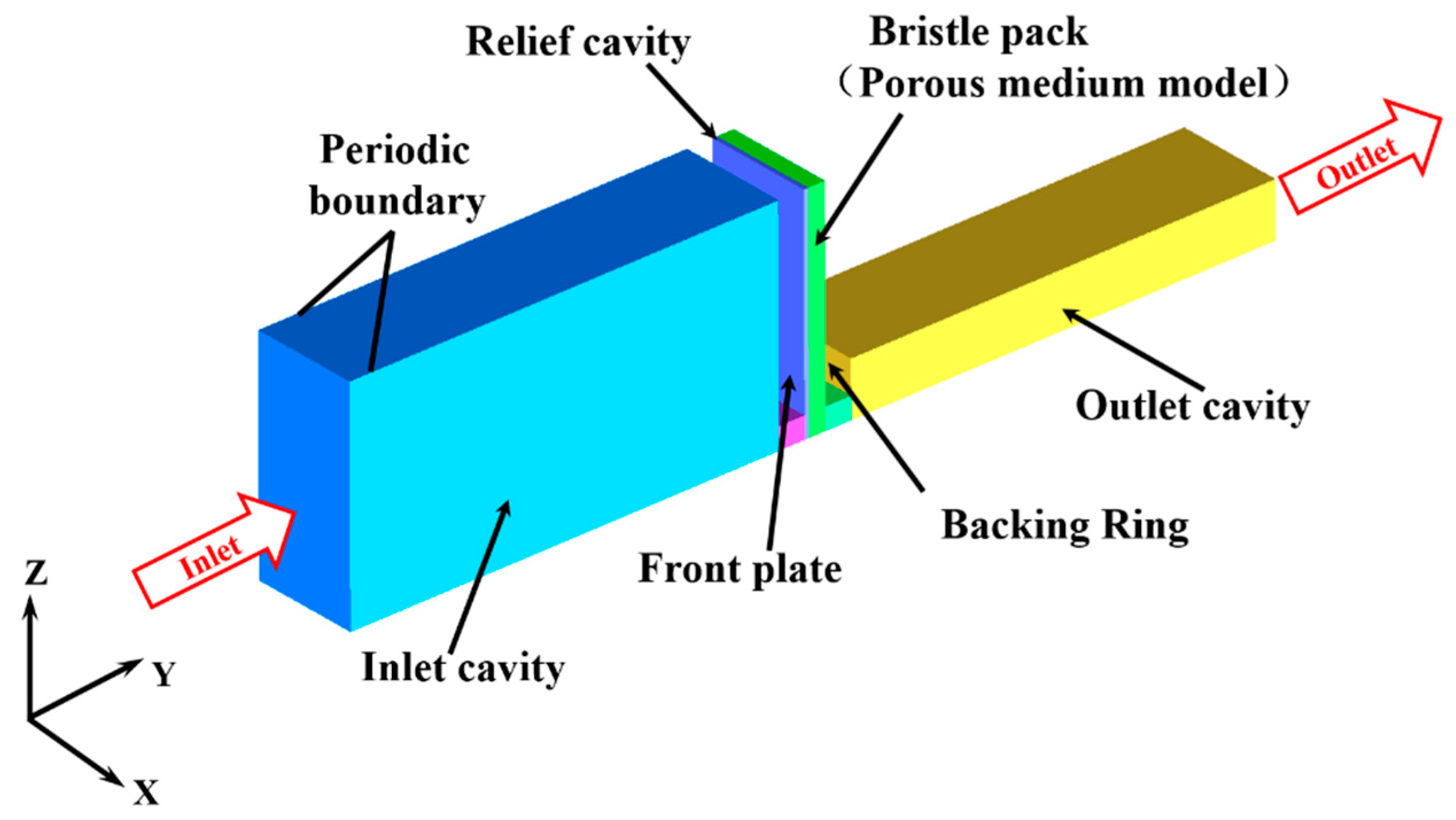
Plane front plate with a relief cavity in the brush seal was regarded as a basic model in this paper. The geometric parameters of the brush seal are summarized in Table 1. Figure 3 presented the computational domain for the baseline, including the inlet cavity, relief cavity, bristle pack and outlet cavity. Assuming a large radius seal, the curvature of the shaft and the rotation of the rotor are neglected in the study, and the clearance between the bristle and the shaft is set to be zero. As shown in the figure, the X–Z coordinates represent the circumferential, axial and radial directions, respectively. The model assumes periodicity in the circumferential direction. Since the aim of the current study is to estimate the flow characteristics upstream of the bristle pack, not within the bristle pack, the bristle pack can thus be simplified as a porous medium model.
Seven different front plate geometries were proposed and modeled to investigate the swirl reducing effect, which are shown in Figure 4. Case-1 was the basic model with a plane front plate, relief cavity, bristle geometric parameters and backing ring. The other six configurations were kept the same as Case-1. Case-2 and Case-3 are designed on the basis of Case-1 and employ one or two axial drilled holes with diameter of 1.5 mm on the front plate. Case-4 is an anti-“L”-type front plate, as shown in Figure 4d, with a reverse axial length of 3 mm. Case-5 is modeled as an anti-“L”-type front plate with an axial drilled hole of 1.5 mm diameter, and Case-6 has a further radial hole in the reverse axial length region. Case-7 is proposed to keep two axial holes based on Case-6.
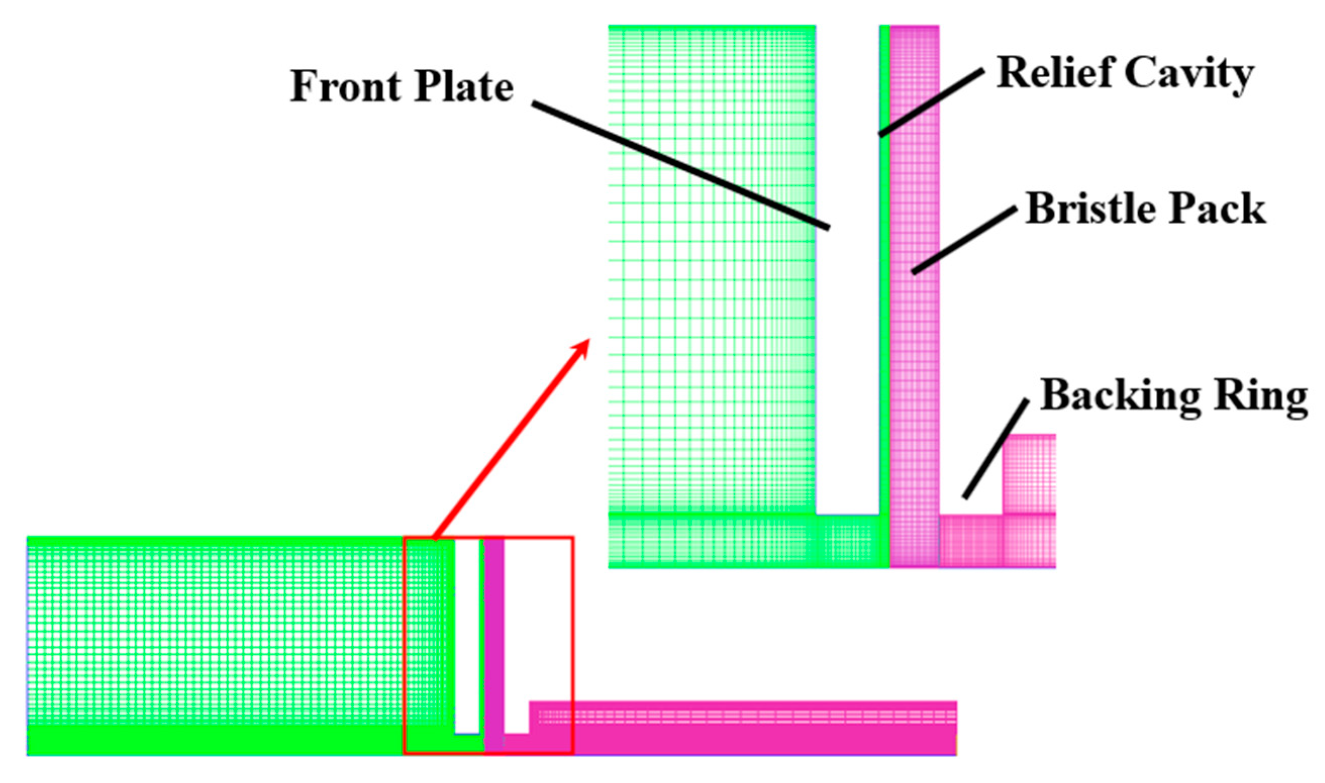
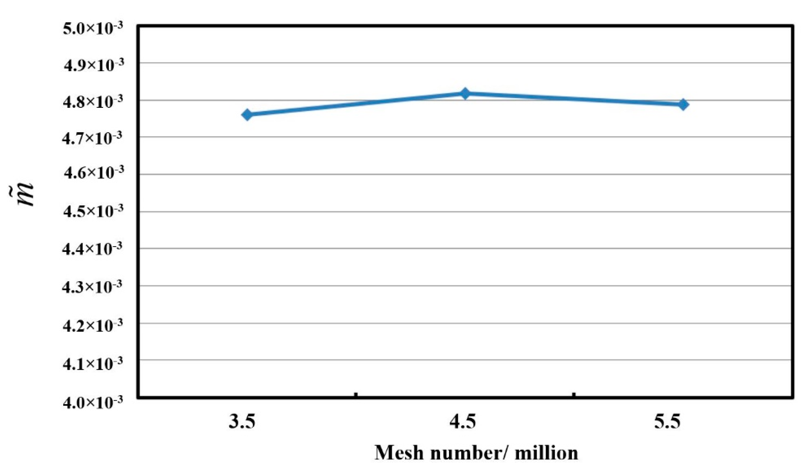
ICEM software was used to generate a hexahedral mesh, as illustrated in Figure 5. In order to improve the calculation accuracy, the mesh is refined through the seal and around the walls. Further details of the porous medium model used for the bristle pack are given below. In order to investigate grid dependency, meshes with about 3.5 million, 4.5 million and 5.5 million cells were considered. To illustrate the grid-independence, the dimensionless mass flow rate [23], which is defined as Expression (1) is plotted in Figure 6, from which it can be seen that the dimensionless mass flow rate differs by 1% for the three mesh numbers. Therefore, 4.5 million mesh was used in the current study.
m ˜ = m ˙ ρ i n V i n A i n

2.2. Numerical Method

The commercial CFD software FLUENT was used to obtain three-dimensional, steady numerical solutions of the flow and energy equations using the k-ε turbulence model and second-order upwind spatial discretization. Air density was calculated based on ideal gas, and physical parameters such as specific heat and viscosity are the functions of temperature. The inlet boundary of a total pressure of 0.5 MPa, a total temperature of 300 K and a circumferential velocity component of 150 m/s was given, and the outlet was specified as a static pressure of 0.1 MPa. Periodic boundary conditions were applied in the circumferential direction, and all further boundaries were assumed to be no-slip and adiabatic. Shaft rotation was not considered here [17]. Standard wall functions were used when imposing the no-slip condition on walls, and the equations were solved using the SIMPLE algorithm. The calculations were considered convergent when the residuals of the continuity equation, energy equation and turbulence equation are all decreased to 10−5 and the typical parameters, such as pressure, velocity and mass flow rate, no longer changed. The overall scalar balances of mass, momentum and energy were also obtained. When the net imbalance was less than 0.001% of the net flux through the domain, the solution was considered converged.

2.3. Porous Medium Model

The bristle pack is composed of many layers of fine bristles that are densely arranged. The airflow passes through the tiny gaps between the bristles under the pressure load. As the main interest here is the condition of the flow approaching the bristles, rather than the detailed flow within the pack, a non-linear, porosity model for the bristles, as first proposed by Chew [9,10], was used. This simplification also ignores any instability of the bristles. That is, any effects of downstream inaccuracy on upstream flow are here assumed small. Chew’s porosity model simulates the flow through the bristle pack by introducing viscosity and inertia losses into the momentum equation, giving
( ρ u i u j ) x j = p x i + τ i j x j + F i
F i = A i j μ u i 0.5 B i j ρ | u | u i
In the equation, Aij is the matrix of viscous resistance coefficient; Bij is the matrix of inertial resistance coefficient. According to reference [24,25], the inertial resistance coefficient along the direction of the bristles is set to be 0, and the other parameters resistance coefficient are obtained as follows:
a z = a n = 66.67 ( 1 ε ) 2 d 2 ε 3
a m = 0.4 ε a n
b z = b n = 2.33 ( 1 ε ) d ε 3
b m = 0
where a and b are the viscosity and inertial resistance coefficients, respectively; z, m and n are the directions that are parallel to the rotating shaft, parallel to the bristles and perpendicular to the bristles, respectively.
Porosity ε refers to the ratio of the void volume to the total volume of the bristle pack in the porous medium and is given by
ε 1 π D 2 N 4 w b sin ϕ
where N is the number of the bristles per unit circumferential length, D the diameter of the brush seal, wb the thickness of the bristle pack and ϕ the angle between the bristle and the tangential direction. The resistance coefficients calculation had been validated by experiments in Ref. [26]. Based on the geometric parameters in Table 1, the porosity of the bristle pack in the current study is 0.192.

2.4. Numerical Method Validation

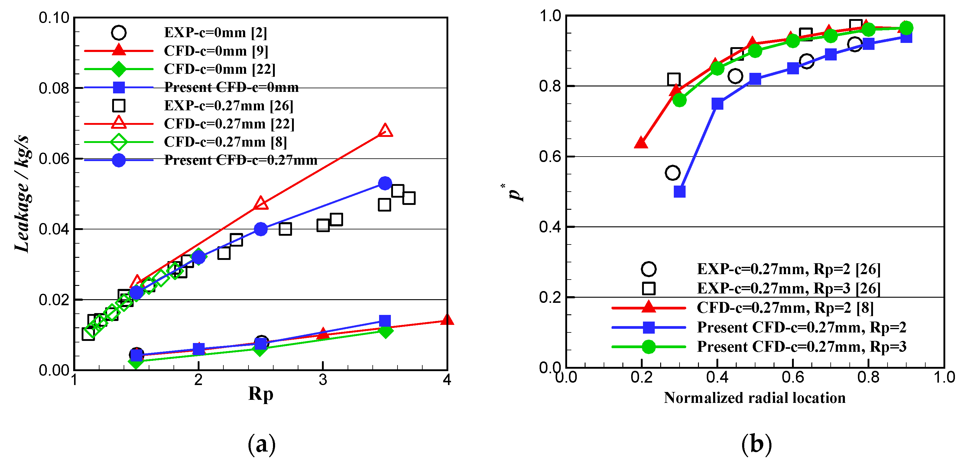
The comparisons of calculated and experimental data published in references were plotted in Figure 7 to validate the numerical method. The calculational model as well as the boundary conditions for validation were consistent with the experiment. Figure 7a compares the leakage flow for brush seals with 0 mm and 0.27 mm radial clearance (c) between the bristle tip and the rotor across a pressure ratio (Rp) of 1 to 4. The non-dimensional pressure variation along the radial backing plate, which is defined as the p* = (ppoutlet)/(pinletpoulet), was shown in Figure 7b. It can be seen that the calculated leakage and pressure distribution are in good agreement with the experimental and numerical results from documents.

3. Analysis and Discussion

3.1. Static Pressure

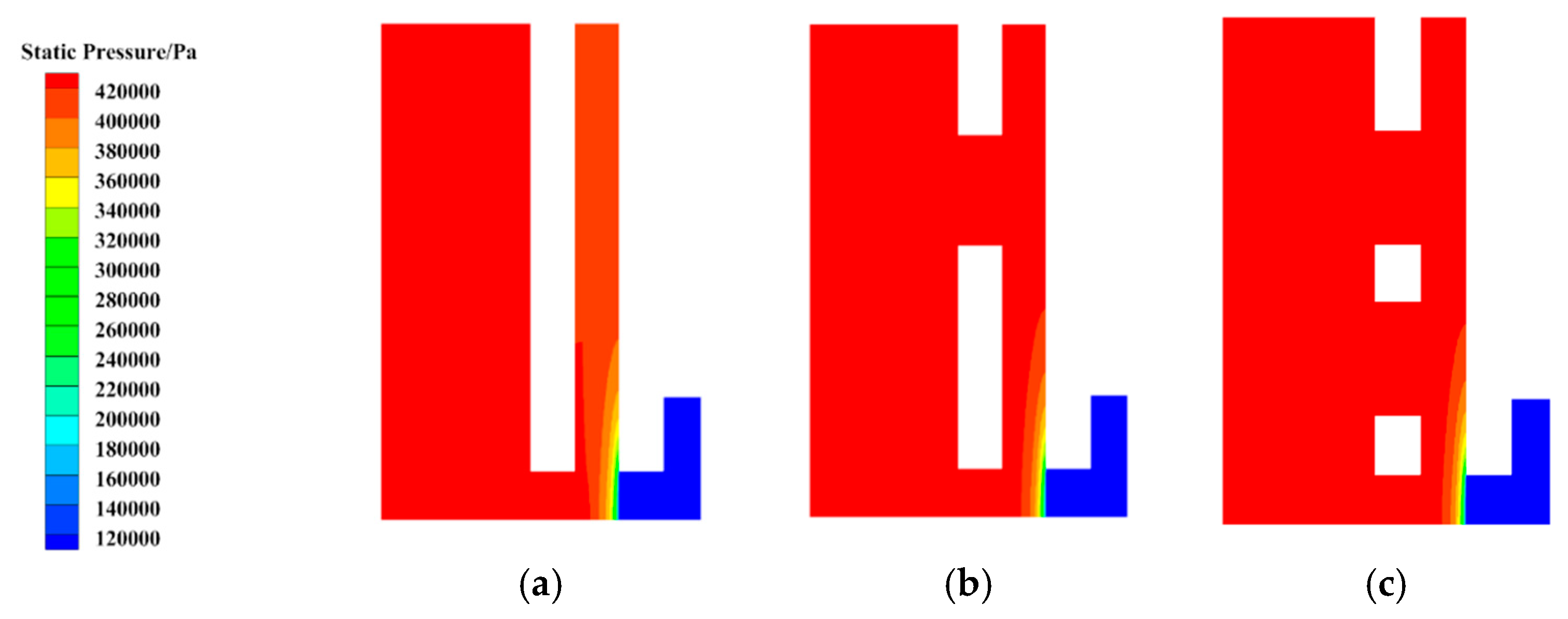
Figure 8 shows the static pressure contour in the brush seal, and pressure contours indicate similar trends for different front plate structures. It is obvious that the static pressure upstream the bristle pack is almost the same. The static pressure in the bristle pack along the axial direction gradually decreases, and the pressure drop near the backing ring corner edge is significant. When the air flows through the backing ring constriction, a part of the pressure energy is converted into kinetic energy accompanying the flow loss. In addition, the static pressure remains basically constant downstream the backing ring.

3.2. Swirl Velocity

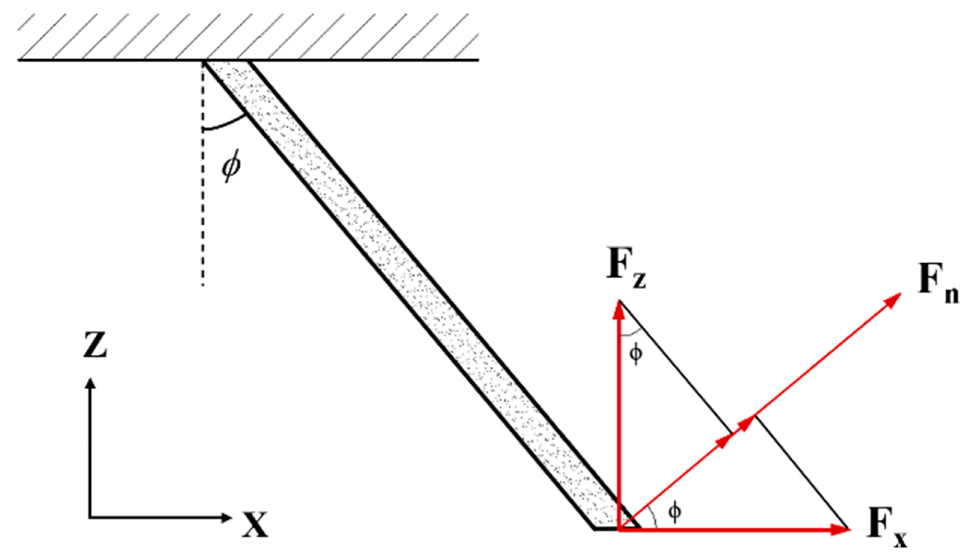
According to ref. [17], it is the ratio of normal-to-axial aerodynamic force on the upstream bristles that determines circumferential slip and aeromechanical instability. In the radial-circumferential plane (X-Z), the normal force Fn is illustrated in Figure 9 and can be expressed as Equation (9). It indicates that with the circumferential force (Fx) decrease and radially inward force (−Fz) increase, the normal force reduces, thereby enhancing the brush seal stability. However, although this force ratio might be estimated from the porous model, this has not been attempted here as the inlet swirl as well as radial velocity immediately upstream of the bristles are considered sufficient to indicate the performance of the front plate geometry and of the normal aerodynamic force acting to displace the bristles.
F n = F x × cos ϕ + F z × sin ϕ
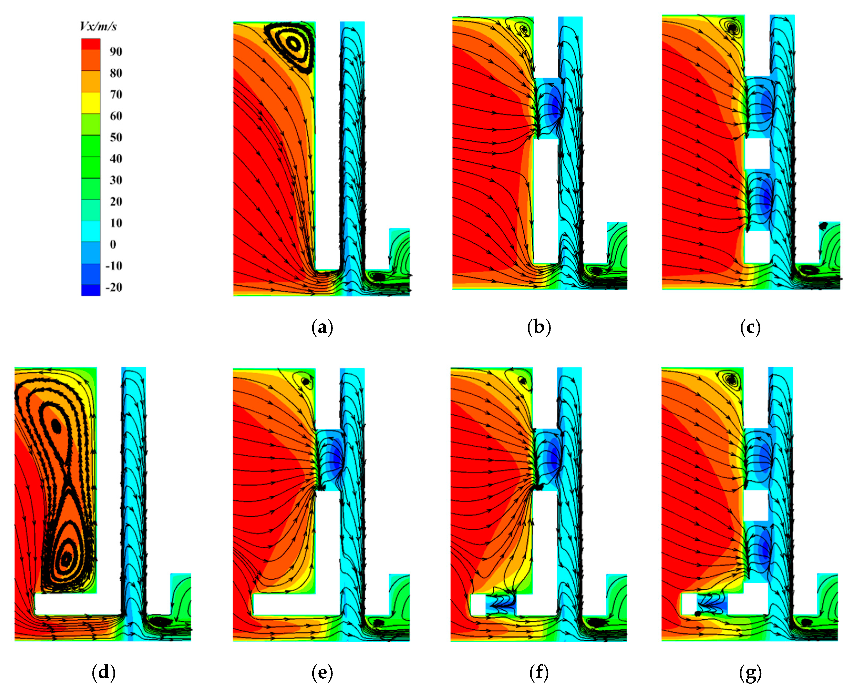
Figure 10 presents swirl velocity contours and streamlines in the Y-Z plane, and a positive value represents a positive direction along the X-axis. For Case 1, the flow is radially inward near the windward surface of the front plate, except for the viscous effect of the plate, this downward flow is largely frictionless and will follow the rule of free-vortex, the flow then pickups swirl when it travels downward. It and then enters into the relief cavity and bristle pack through the space between the tip of the plate and the shaft. In the bristle pack, the airflow is disturbed by closely arranged bristles, resulting in energy dissipation. The swirl velocity is reduced or negated as it passes through the bristle pack due to the strong resistance. Only bristle tips are exposed to the high swirl velocity directly due to the existence of the front plate. Based on Case-1, axial drilled holes 2-A were placed at the front plate for Case-2. The vortex near the root of the front plate becomes smaller with part of flow through drilled holes into the bristle pack, which can alleviate the flow squeeze and decline the swirl velocity gradient upstream the plate. When air entering through holes is resisted by the wall, the swirl velocity decreases and even negative circumferential velocity is observed locally. Meanwhile, the flow spreads around near the hole outlet and suppresses outward radial flow in the relief cavity, resulting in lower swirl velocity upstream the bristle tips compared with Case-1. As for Case-3, another axial drilled holes 3-B were added at the front plate compared with Case-2. Much more flow transports to the bristle pack through axial holes, further reducing the swirl in the relief cavity as well as just upstream of the bristle tips.
As shown in Figure 10d, an anti-“L”-type plate was applied to Case-4. Two large vortices are generated at the reverse axial length region upstream the front plate. The airflow goes through a relatively long channel to the relief cavity and bristle pack due to the reverse axial length, leading to a little swirl reduction upstream the bristle tips. In addition, the flow field is similar with Case-1 in the bristle pack and after the backing ring corner. For Case-5, axial drilled holes 5-A were placed at the anti-“L”-type plate. The larger vortices upstream the front plate are basically eliminated with additional flow through the plate holes. Compared with Case-2, the flow characteristics for axial holes with local flow impingements in the relief cavity are similar, but below the front plate bottom where the bristles are exposed, the swirl velocity is a little reduced thanks to the existence of the reverse axial length. On the basis of Case-5, radial holes (6-B) were located on the reverse axial length for Case-6. A part of flow is delivered from above the anti-“L” structure to below, and this flow injection causes the swirl velocity to weaken slightly at the upstream of the bristle tips. Additionally, the comparison of flow structures between the radial hole 6-B and axial hole 6-A shows that the axial holes tend to have stronger resistance to swirl flow. For Case-7, axial holes 7-B were extra set to the front plate, and the swirl is further reduced upstream the bristles. The combined flow control schemes of the anti-“L”-type plate, axial holes and radial holes yield the best effect on swirl reduction in Case-7.

3.3. Radial Velocity

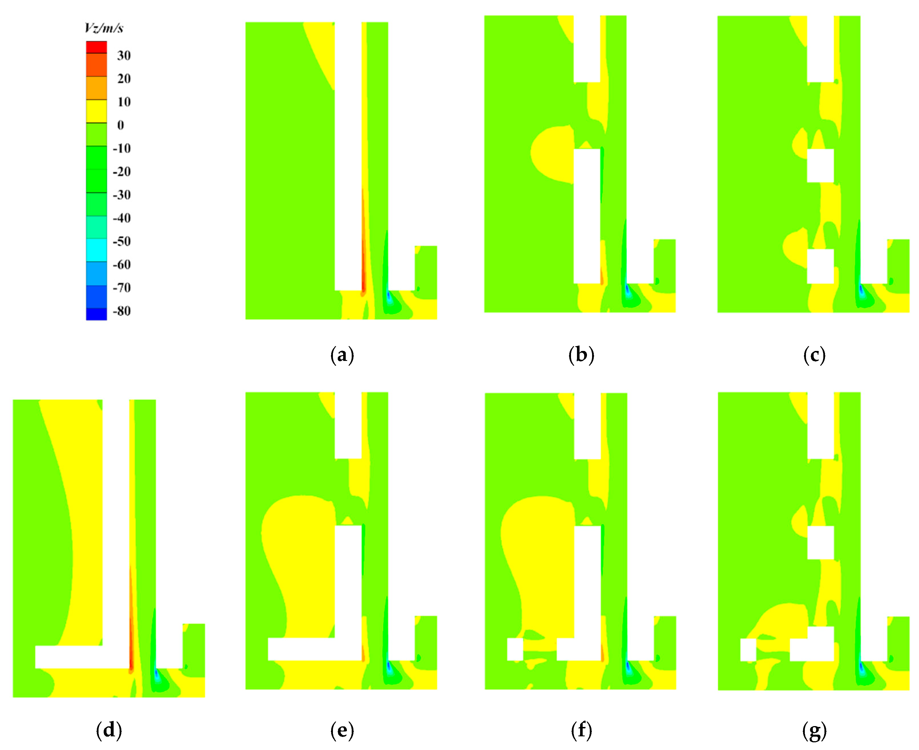
Figure 11 shows radial velocity contours for different cases, and negative values represent radially inward flow. For the basic model Case-1, the long front plate deflects the flow radially inwards and generates radially outward flow at the inner edge of the front plate as well as within the relief cavity. The tortuous, narrow flow path between the bristles provides resistance to the flow and directs the flow radially inwards towards the corner edge of the backing ring. In and after the bristle pack, the variations of radial velocity for different cases are almost the same.
For Cases with axial holes at the front plate, the flow will be divided into inward and outward directions inside the holes, interrupting the original radially outward flow in the relief cavity downstream the holes. Moreover, increasing the number of axial holes improves radially inward flow in the relief cavity, which can pull the bristles radially towards the rotor and enhance the blow-down effect, thereby increasing the brush seal stability. In addition, more outward radial flow is obtained upstream the anti-“L”-type front plate and under the reverse axial length. Even with airflow through axial holes in Cases-5 and Case-7, slightly outward flow still remains upstream the front plate. Furthermore, the radial holes reduce the radial outflow upstream of the bristle tips.

3.4. Flow Fields Analysis in Relief Cavity

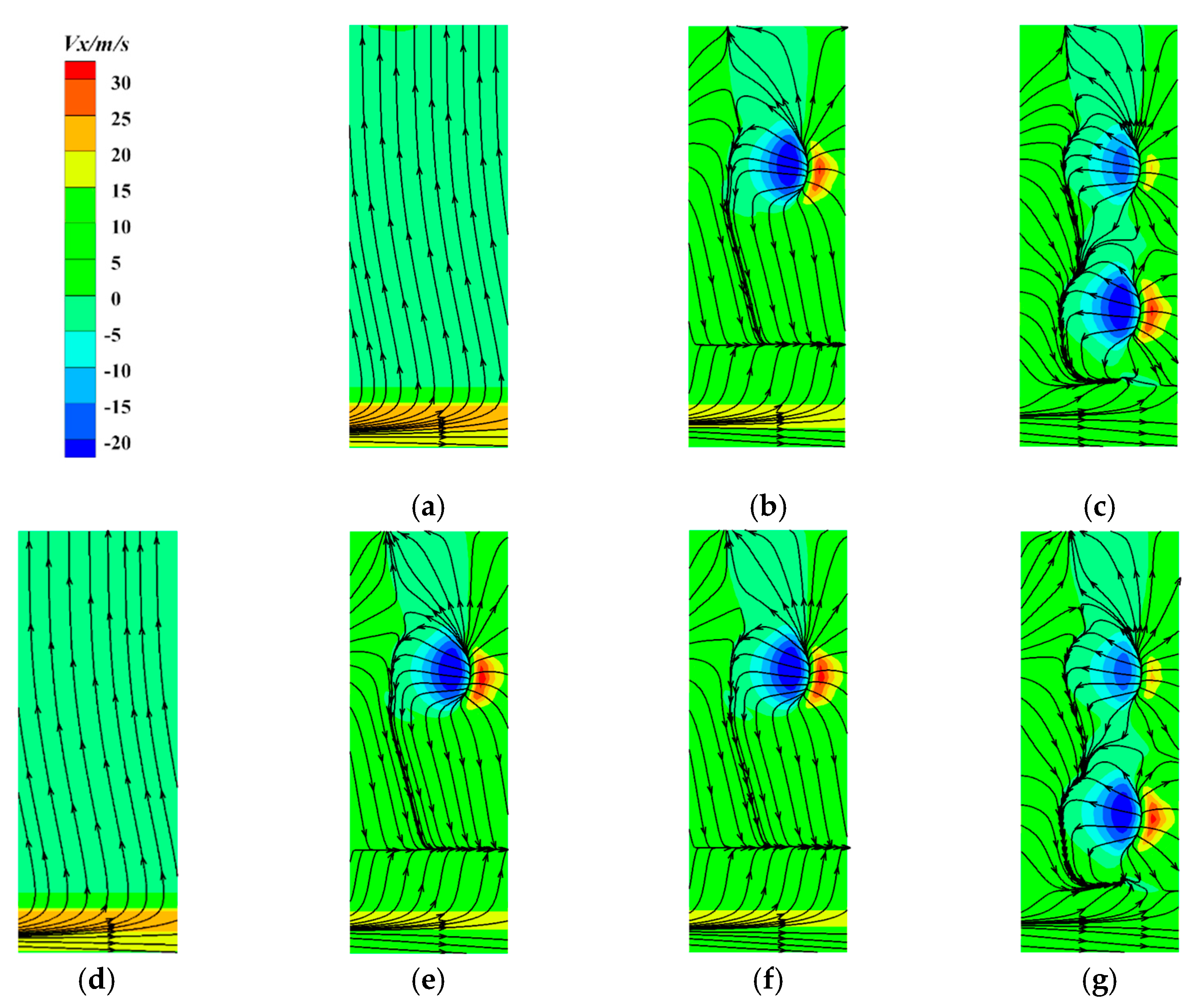
To further analyze the flow fields approaching the bristle pack, the contours of the swirl velocity with streamlines on the plane 0.1 mm upstream of the bristle pack in the relief cavity are shown in Figure 12. As previously discussed, the flow is radially outwards in the relief cavity, and the higher swirl velocity is mainly distributed at the inner diameter of the cavity upstream of the bristle tips in Case-1. For front plates with axial holes, the air flow disperses around in the cavity after passing through the holes due to the resistance of the bristle pack, resulting in local higher positive and negative swirl velocities. Moreover, the airflow from circumferentially adjacent axial holes will impinge and mix with each other, forcing some flows radially inwards. These flow impingements through front plate holes promote the blow-down effect of bristles and contribute to a significant reduction in swirl at the inner diameter of the cavity.
For Case 4 with the anti-“L”-type front plate, the flow field in the relief cavity is basically the same as that of Case-1 except slightly lower swirl velocity distribution upstream of the bristle tips. By comparing Case-2 and Case-5, as well as Cases-3 and Case-7, it can also be seen that the anti-“L”-type plate plays a certain role in reducing the swirl at the inner diameter. Meanwhile, the comparison between Case-5 and Case-6 indicates that the radial holes on the reverse axial length appear to have little effect upon the swirl reduction.

3.5. Swirl Velocity Variation along Axial Direction

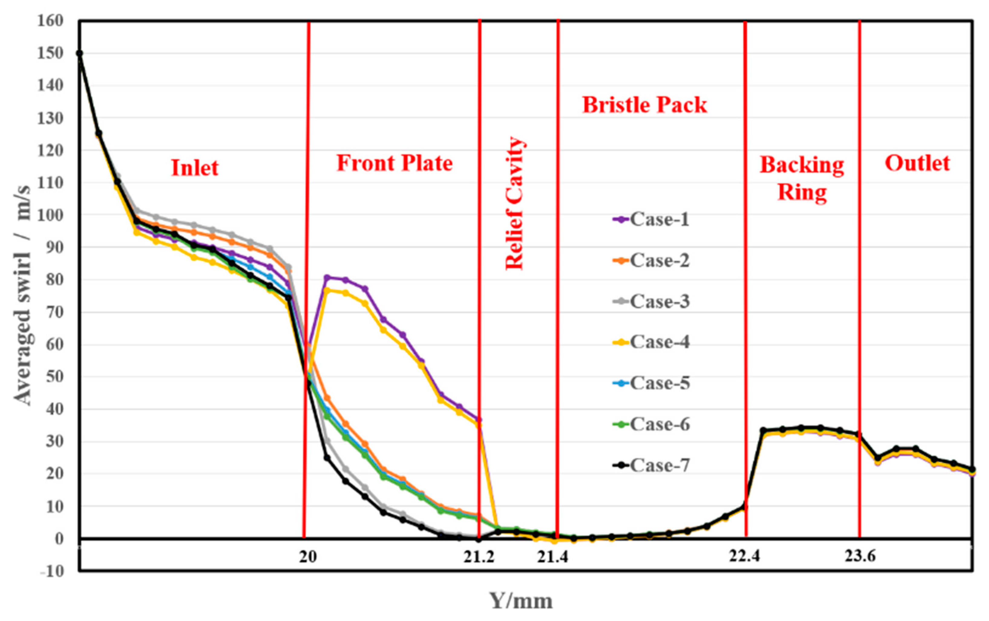
Flow fields analysis could only qualitatively clarify the main functions of the front plate configuration, axial hole and radial hole on the swirl reduction. In order to further quantitatively display the effect, Figure 13 shows the area-averaged swirl velocities on planes of constant axial position for the seven front plate models. It can be seen that the variations of area-averaged swirl velocity for different models are similar, and the value decreases sharply at the front end of the front plate and then slowly decreases to the back end of the front plate due to the presence of a large number of vortices in the axial and radial holes, which is the same as explained in Section 3.2. Consequently, the swirl velocities upstream of the bristle pack are relatively lower than those of Case-1 and Case-4.
Table 2 gives the average swirl velocities on the plane 0.2 mm upstream of the bristle pack. The results indicate that the value for the baseline model (Case-1) is the highest of those investigated, at about 36.7 m/s. Comparing Case-4 to Case-1, the anti-“L”-type front plate is better at reducing the swirl flow, which is consistent with the above analysis. In addition, considering the plane front plate of Case-1, Case-2 and Case-3 and evaluating the anti-“L”-type plate of Case-4, Case-6 and Case-7, it can be found that the swirl velocity reduces with the number of axial holes. On the basis of the plane front plate model in Case-1, one axial hole design decreases the swirl around 28%, and two axial holes will reduce significantly by 42%. The swirl velocity upstream the bristle pack for Case-6 is lower than that of Case-5, which also demonstrates the positive effect of radial holes. In summary, Case-7, which has two axial holes and one radial hole on the anti-“L”-type front plate, shows the best performance on reducing swirl flow. The value for Case-7 can be declined 50% compared to the baseline model. This leads to the circumferential aerodynamic forces on the bristles, which scale with the swirl dynamic head, reducing by a factor of 4, thereby controlling the adverse circumferential slip of the bristle and increasing the brush seal stability significantly.

3.6. Leakage Characteristics

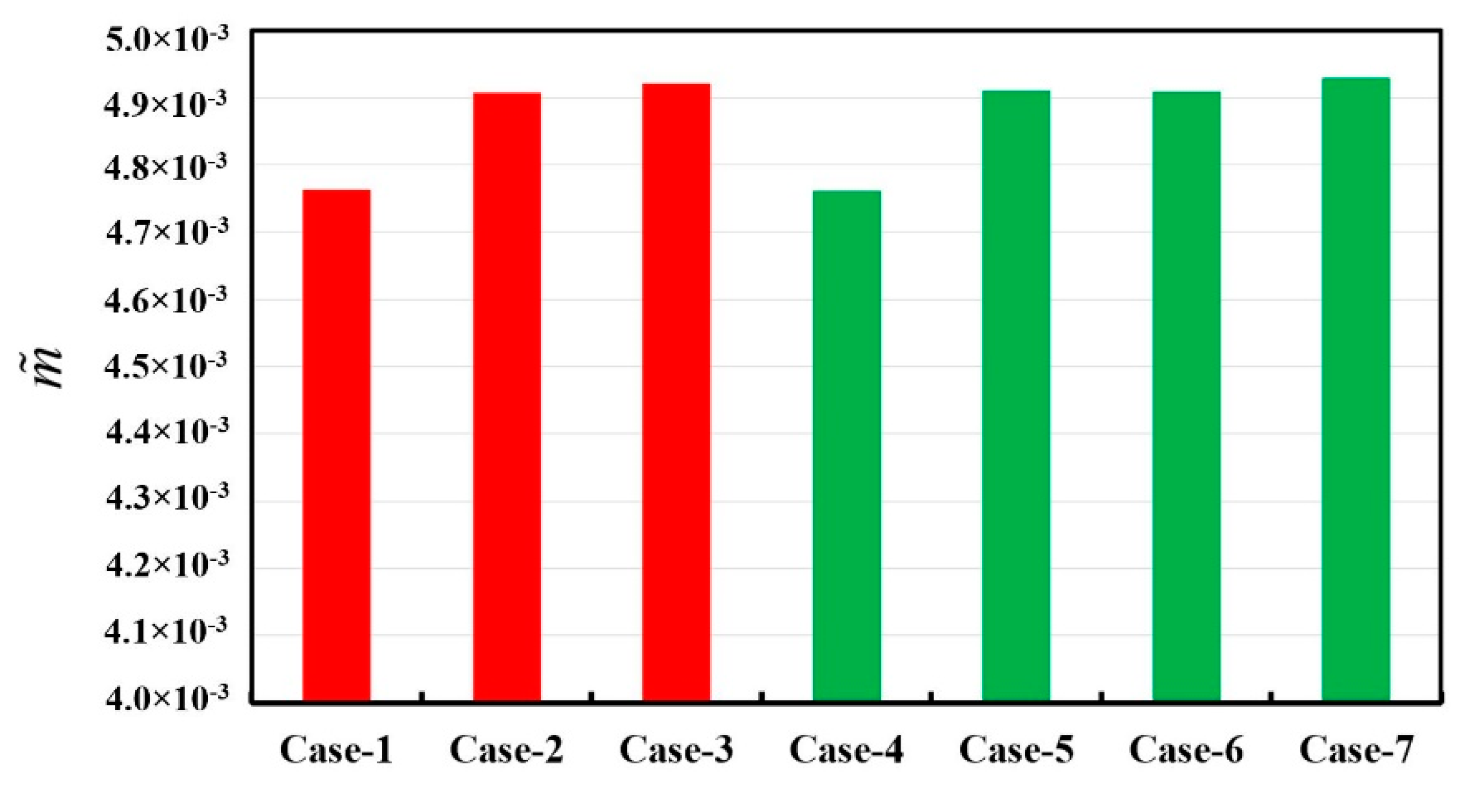
The dimensionless leakage mass flow rates, as defined by Equation (1), for seven models defined as Equation (1) are shown in Figure 14. It can be observed that the leakage flow rates for the model with the plane front plate are similar with those with the anti-“L”-type front plate, all between 4.76 × 10⁻³ to 4.93 × 10⁻³. The axial holed design will increase the leakage flow rate by around 3.5% due to the enlarged flow area upstream the bristle pack, and consequently, the leakage rises with the axial hole number slightly. However, the radial holed design has almost no impact on the leakage flow rate.

4. Conclusions

Seven types of front plate geometries were proposed and compared on the brush seal’s flow fields and leakage characteristics in the current study. The analysis was mainly focused on the effect of reducing the swirl velocity upstream of the bristle pack and hence protecting the bristle from destabilizing aerodynamic forces. The main conclusions are summarized as follows.
  • The flow through the front plate axial holes generate an inward radial flow in the relief cavity to suppress the upward tendance of the flow in the cavity. This can promote the blow-down effect of bristles and result in a significant reduction in swirl upstream of the bristle tips. This will reduce the circumferential forces impacting the bristle pack, thereby enhancing the stability of bristle.
  • The anti-“L”-type front plate leads to large vortices near the windward surface of the front plate and relatively long channel before the bristle tips, both help to decrease the swirl velocity slightly. However, the radial holes on the reverse axial length appear to have little effect upon the swirl reduction.
  • Compared to the plane front plate model, one axial hole designed structure decreases the swirl around 28%, and the application of two axial holes further reduce the value by 42%. Case-7, which has two axial holes and one radial hole on the anti-“L”-type front plate, shows the best performance in reducing swirl. The swirl velocity upstream the bristle pack is declined 50%, reaching 18.4 m/s, which can result in the circumferential aerodynamic force being reduced by a factor of 4.
  • Front plate configuration will not affect the leakage dramatically, while the axially designed hole on the front plate increases the leakage slightly by around 3.5%.

Author Contributions

Conceptualization, Y.L. and X.K.; methodology, B.Y.; validation, Y.L.; formal analysis, Y.L.; investigation, B.Y.; writing—original draft preparation, Y.L. and B.Y.; writing—review and editing, X.K., H.L. and H.C.; visualization, Y.L. and B.Y.; supervision, H.C.; project administration, X.K.; funding acquisition, Y.L. and X.K. All authors have read and agreed to the published version of the manuscript.

Funding

This research was funded by the National Natural Science Foundation of China (No. 52106040, No. 52006021), the Dalian Science and Technology Innovation Fund (No. 2021JJ12GX030), the Natural Science Foundation of Liaoning Province (No. 2020-BS-069), Postdoctoral Research Foundation of China (No. 2021M700648, No. 2021M690498) and the Fundamental Research Funds for the Central Universities (No. 3132021110).

Institutional Review Board Statement

Not applicable.

Informed Consent Statement

Not applicable.

Data Availability Statement

Not applicable.

Conflicts of Interest

The authors declare no conflict of interest.

Nomenclature

AArea, m2
aViscous resistance coefficient
bInertial resistance coefficient
DBristle diameter, m
HHeight of bristle overhang, m
LbBristle length, m
m ˜ dimensionless mass flow rate
NNumber of the bristles per unit circumferential length, bristles/mm
p*Non-dimensional pressure = (ppout)/(pinpout)
RRadial location, m
RpPressure ratio
rRadius of axial/radial hole, m
X, Y, ZCircumferential, axial, radial direction respectively
wbThickness of the bristle pack, m
ZrotorRadial Clearance between Bristles and Rotor, m
δMinimum clearance between bristles, m
εPorosity of the bristle pack
ρDensity of the flow, kg/m3
ϕIncline angle of bristle pack
Subscripts
inAt system inlet
mParallel to the bristles
nPerpendicular to the bristles
zParallel to the rotating shaft

References

  1. Chupp, R.E.; Ghasripoor, F.; Turnpuist, N.A.; Demiroglu, M.; Aksit, M.F. Advanced seals for industrial turbine applications: Dynamics seal development. J. Propuls. Power 2002, 18, 1260–1266. [Google Scholar] [CrossRef]
  2. Bayley, F.J.; Long, C.A. A combined experimental and theoretical study of flow and pressure distributions in a brush seal. J. Eng. Gas Turbines Power 1993, 115, 404–410. [Google Scholar] [CrossRef]
  3. Hur, M.S.; Moon, S.W.; Kim, T.S. A Study on the Leakage Characteristics of a Stepped Labyrinth Seal with a Ribbed Casing. Energies 2021, 14, 3719. [Google Scholar] [CrossRef]
  4. Basu, P.; Datta, A.; Loewenthal, R.; Short, J.; Johnson, R. Hysteresis and bristle stiffening effects in brush seals. J. Propuls. Power 1994, 10, 569–575. [Google Scholar] [CrossRef]
  5. Stango, R.J.; Zhao, H.; Shia, C.Y. Analysis of contact mechanics for rotor-bristle interference of brush seal. J. Tribol. 2003, 125, 414–420. [Google Scholar] [CrossRef]
  6. Zhao, H.; Stango, R.J. Effect of flow-induced radial load on brush/rotor contact mechanics. J. Tribol. 2004, 126, 208–214. [Google Scholar] [CrossRef]
  7. Zhao, H.; Stango, R.J. Analytical approach for investigating bristle/backplate hysteresis phenomenon in brush seals. J. Propuls. Power 2007, 23, 273–282. [Google Scholar] [CrossRef]
  8. Sun, D.; Liu, N.; Fei, C.; Hu, G.Y.; Ai, Y.T.; Choy, Y.S. Theoretical and Numerical Investigation on the Leakage Characteristics of Brush Seals Based on Fluid-Structure Interaction. Aerosp. Sci. Technol. 2016, 58, 207–216. [Google Scholar] [CrossRef]
  9. Chew, J.W.; Lapworth, B.L.; Millener, P.J. Mathematical modeling of brush seals. Int. J. Heat Fluid Flow 1995, 16, 493–500. [Google Scholar] [CrossRef] [Green Version]
  10. Chew, J.W. Porosity modeling of brush seals. J. Tribol. 1997, 19, 769–775. [Google Scholar] [CrossRef]
  11. Li, J.; Yan, X.; Feng, Z.; Shengke, J.; Xianglin, K.; Qi, S.; Jianlu, W. Study on the Leakage Flow Characteristics of Brush Seal Based on Porous Medium Model. J. Xi’an Jiaotong Univ. 2007, 41, 768–779. [Google Scholar]
  12. Sharatchandra, C.; Rhode, L. Computed Effects of Rotor-Induced Swirl on Brush Seal Performance-Part 2: Bristle Force Analysis. J. Tribol. 1996, 118, 920–926. [Google Scholar] [CrossRef]
  13. Helm, P.; Pugachev, A.; Neef, M. Breaking the Swirl with Brush Seals: Numerical Modeling and Experimental Evidence. In Proceedings of the ASME Turbo Expo 2008: Power for Land, Sea and Air, Berlin, Germany, 9–13 June 2008; p. GT2008-50257. [Google Scholar]
  14. Choi, S.M.; Choi, S.; Cho, H.H. Effect of Various Coolant Mass Flow Rates on Sealing Effectiveness of Turbine Blade Rim Seal at First Stage Gas Turbine Experimental Facility. Energies 2020, 13, 4105. [Google Scholar] [CrossRef]
  15. Outirba, B.; Hendrick, P. Influence of Geometrical Parameters on the Performance of Brush Seals for Aero-Engines Bearing Chambers. In Proceedings of the ASME Turbo Expo 2015: Turbine Technical Conference and Exposition, Montreal, QC, Canada, 15–19 June 2015; p. GT2015-43519. [Google Scholar]
  16. Aksit, M.; Dogu, Y.; Tichy, J.; Gursoy, M. Hydrodynamic Lift of Brush Seals in Oil Sealing Applications. In Proceedings of the 40th AIAA/ASME/SAE/ASEE Joint Propulsion Conference and Exhibit, Fort Lauderdale, FL, USA, 11–14 July 2004; p. AIAA 2004-3721. [Google Scholar]
  17. Liu, Y.; Chew, J.W.; Pekris, M.J.; Kong, X. The Effect of Inlet Swirl on Brush Seal Bristle Deflections and Stability. J. Eng. Gas Turbines Power 2020, 142, 071002. [Google Scholar] [CrossRef]
  18. Kong, X.; Huang, T.; Liu, Y.; Chen, H.; Lu, H. Fluid-Structure Interaction Study on the Effect of Inlet Swirl on the Brush Seal Bristle Deflections. J. Eng. Thermophys. 2021, 42, 1224–1232. [Google Scholar]
  19. Chi, J.; Wang, Z. Analysis of front plate’s effect on low hysteresis brush seal. J. Aerosp. Power 2012, 27, 1902–1906. [Google Scholar]
  20. Dogu, Y.; Aksit, M.F. Effects of geometry on brush seal pressure and flow fields-I: Front plate configurations. J. Turbomach. 2006, 128, 367–378. [Google Scholar] [CrossRef]
  21. Dogu, Y.; Akist, M.F.; Demiroglu, M. Evaluation of flow behavior for clearance brush seals. J. Eng. Gas Turbines Power 2008, 130, 012507-1–012507-9. [Google Scholar] [CrossRef]
  22. Dogu, Y.; Bahar, A.S.; Sertcakan, M.C.; Pişkin, A.; Arıcan, E.; Kocagül, M. Computational fluid dynamics investigation of brush seal leakage performance depending on geometric dimensions and operating conditions. J. Eng. Gas Turbines Power 2016, 138, 032506-1–052506-13. [Google Scholar] [CrossRef]
  23. Kong, X.; Liu, Y.; Lu, H.; Tian, Z.; Xin, J. Performance Analysis of Inter-Stage Leakage Flows at Rotating Conditions in an Axial Compressor. J. Therm. Sci. 2020, 29, 1558–1568. [Google Scholar] [CrossRef]
  24. Zhang, Y.; Yan, J.; Li, J. Investigations on Leakage Flow Characteristics of Brush Seal with Consideration of Blow down Effect. Lubr. Eng. 2017, 42, 36–42. [Google Scholar]
  25. Hildebrandt, M.; Schwitzke, C.; Bauer, H.J. Analysis of Heat Flux Distribution during Brush Seal Rubbing Using CFD with Porous Media Approach. Energies 2021, 14, 1888. [Google Scholar] [CrossRef]
  26. Turner, M.T.; Chew, J.W.; Long, C.A. Experimental Investigation and Mathematical Modelling of Clearance Brush Seals. J. Eng. Gas Turbines Power 1998, 120, 573–579. [Google Scholar] [CrossRef]
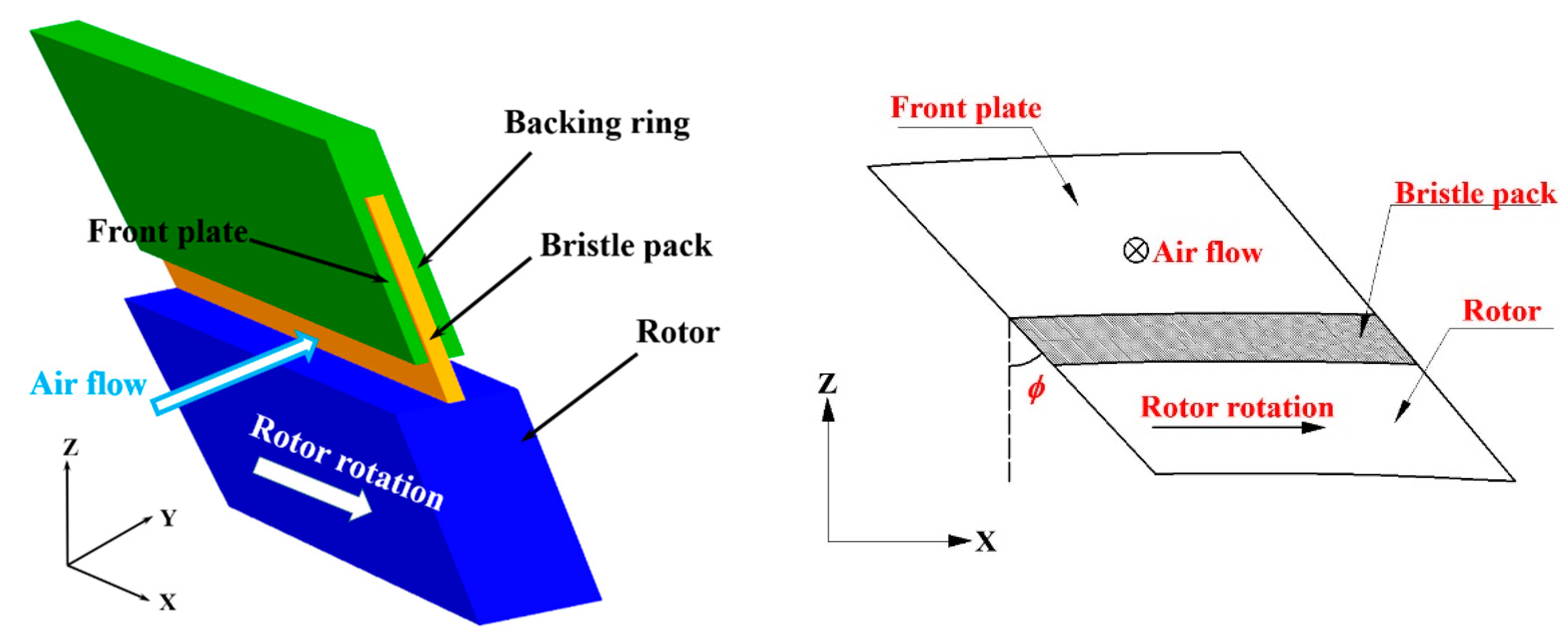
Figure 1. Brush seal structure.
Energies 14 07768 g001
Figure 2. Circumferential slip of bristles at swirl velocity of 250 m/s. (a) Bristle centerlines on the axial—radial plane. (b) Bristle tips on the axial—circumferential plane.
Energies 14 07768 g002
Figure 3. Computational domain.
Energies 14 07768 g003
Figure 4. Seven configurations of the front plate: (a) Case-1; (b) Case-2; (c) Case-3; (d) Case-4; (e) Case-5; (f) Case-6; (g) Case-7.
Energies 14 07768 g004
Figure 5. Mesh generation.
Energies 14 07768 g005
Figure 6. Mesh Independence Study.
Energies 14 07768 g006
Figure 7. Comparisons of the present results with previously published data: (a) leakage flow; (b) pressure variation along radial backing plate.
Energies 14 07768 g007
Figure 8. Static pressure contours: (a) Case-1; (b) Case-2; (c) Case-3; (d) Case-4; (e) Case-5; (f) Case-6; (g) Case-7.
Energies 14 07768 g008aEnergies 14 07768 g008b
Figure 9. Diagram for normal aerodynamic force on bristles.
Energies 14 07768 g009
Figure 10. Swirl velocity contours and streamlines: (a) Case-1; (b) Case-2; (c) Case-3; (d) Case-4; (e) Case-5; (f) Case-6; (g) Case-7.
Energies 14 07768 g010
Figure 11. Radial velocity contours: (a) Case-1; (b) Case-2; (c) Case-3; (d) Case-4; (e) Case-5; (f) Case-6; (g) Case-7.
Energies 14 07768 g011
Figure 12. Swirl velocity contours and streamlines on the plane 0.1 mm upstream of the bristle pack: (a) Case-1; (b) Case-2; (c) Case-3; (d) Case-4; (e) Case-5; (f) Case-6; (g) Case-7.
Energies 14 07768 g012
Figure 13. Swirl velocity variation for different models.
Energies 14 07768 g013
Figure 14. Dimensionless leakage flow rate.
Energies 14 07768 g014
Table 1. Geometric parameters for the baseline model.
Lay Angle to Radial Directionϕ40°
Bristle DiameterD0.10 mm
Bristle Lengthl13.35 mm
Height of Bristle OverhangH1.00 mm
Number of Axial Rows 10
Minimum Clearance between Bristlesδ0.004 mm
Radial Clearance between Bristles and RotorZrotor0 mm
Axial length of Front PlateLFP1.2 mm
Axial length of Backing RingLBR1.2 mm
Axial length of Relief cavityLRC0.2 mm
Table 2. Averaged swirl velocity on the plane 0.2 mm upstream of the bristle pack.
ModelAveraged Swirl Velocity
Case-136.7 m/s
Case-226.5 m/s
Case-321.4 m/s
Case-435.1 m/s
Case-524.8 m/s
Case-624.1 m/s
Case-718.4 m/s
Publisher’s Note: MDPI stays neutral with regard to jurisdictional claims in published maps and institutional affiliations.