Abstract
Hydro-viscous clutch is a speed-regulating device for heavy fans and water pumps. It has important engineering significance in the fields of soft-start for rotating machinery. More and more attention has been paid to its torque and control characteristics. This paper is focused on the torque formula for hydro-viscous clutch (HVC), assuming that multi-friction plates distribute ununiformly with different oil film thickness. A mathematical model of friction plates was constructed, then the distribution formula of the oil film thickness was obtained. A new expression was presented using a modified factor. Parameters such as pressure, viscous torque, and oil film thickness were obtained. The results show that each clearance of friction plates is not the same and the distribution of oil film thickness is influenced by pressing force, groove depth, angular ratio of groove/non-groove, and static friction force. To verify the proposed expression, relevant experiments were carried out on an HVC with multi-friction plates, and the experimental results indicate that the new expression is more accurate compared to the original one.
1. Introduction
Hydro-viscous drive is a new branch of fluid power transmission, in which the power is transmitted by fluid shear based on the Newton inner friction law. In some applications, such as speed regulation of heavy fans and pumps, hydro-viscous clutch (HVC) is used for energy-saving. The output torque of HVC can be regulated by changing the clearance between friction plates, which are the core factor that affects HVC’s performance [1,2,3]. In recent years, HVC has been used in super large engineering applications, such as tunnel boring machines, and higher requirements for its control accuracy are put forward. More and more artificial intelligence learning algorithms are used in the control strategy of HVC [4,5,6,7].
Ideally, the clearance between friction pair is the same and filled with transmission oil. Heat can be taken away while HVC transmits torque. Under this situation, the original expression of torque for HVC predicts the real torque quite well. However, the clearance is quite different in practice. Moreover, problems such as overheating, warping deformation, and serious damage often occur when HVC is working [8,9,10,11]. After disassembling the clutch, it was found that friction plates close to the side of the piston were seriously worn, while the other side suffered no damage [12]. Studies have shown that the oil film uniformity of HVC can be improved by optimizing structure design [13,14,15].
Since the original expression is simplified by the assumption that all the clearances between plates are the same, relevant research can be done for the opposite assumption. Researchers have made some progress in the mathematical model of viscous torque and the flow field simulation of plates for HVC [16,17,18].
Huang et al. [19] revealed the effect of groove on behavior of flow between hydro-viscous drive plates. The results showed that viscous torque decreases obviously when groove number increases, while it changes a little when groove depth increases. Cui et al. [20] studied the mathematical model of fluid torque by shear stress under the influence of fluid temperature in HVC. The results showed that the film torque caused can be predicted correctly by an equivalent radius model and mathematical model. Yao et al. [21]. Established the numerical film torque modeling of friction pair in HVC and pointed out that film torque of a radial grooved plate was less than the vertical–horizontal grooved plate. Yuan et al. [22] developed a mathematical model that incorporates the surface tension effects, which can predict the drag torque well for a disengaged wet clutch. Hu et al. [23] proposed a drag torque model for the wet clutches, which take the shrinking effect of oil film into account. Razzaque et al. [24] analyzed the film flow between plates in the wet clutches under the consideration of groove geometry and orientation. Aphale et al. [25] investigated both a 2D lubrication model and 3D computational fluid dynamics model to evaluate the film torque with the consideration of grooves. Huang et al. [26] studied the flow field of the oil film between plates in hydro-viscous drive and the distribution of temperature and pressure by means of numerical simulation.
From the above-mentioned literature review, it can be found that the mathematical model of viscous torque, the flow between one single friction pair, and the effect of grooves on torque characteristics was well studied. However, the research object of those studies only focused on a single friction plate in HVC. In fact, HVC consists of many friction plates. As a result of the force interaction of every oil film, each clearance between a friction pair is quite different. Therefore, it would be inappropriate to obtain the overall torque of HVC according to the torque of a single friction pair.
In this paper, a new expression of torque for hydro-viscous clutch is given in the condition that each clearance of friction plates is different. Then, how parameters influence the distribution of clearance and the overall torque are presented. Finally, relevant experiments were carried out on an HVC with multi-friction plates.
2. Structure and Work Principle of Hydro-viscous Clutch
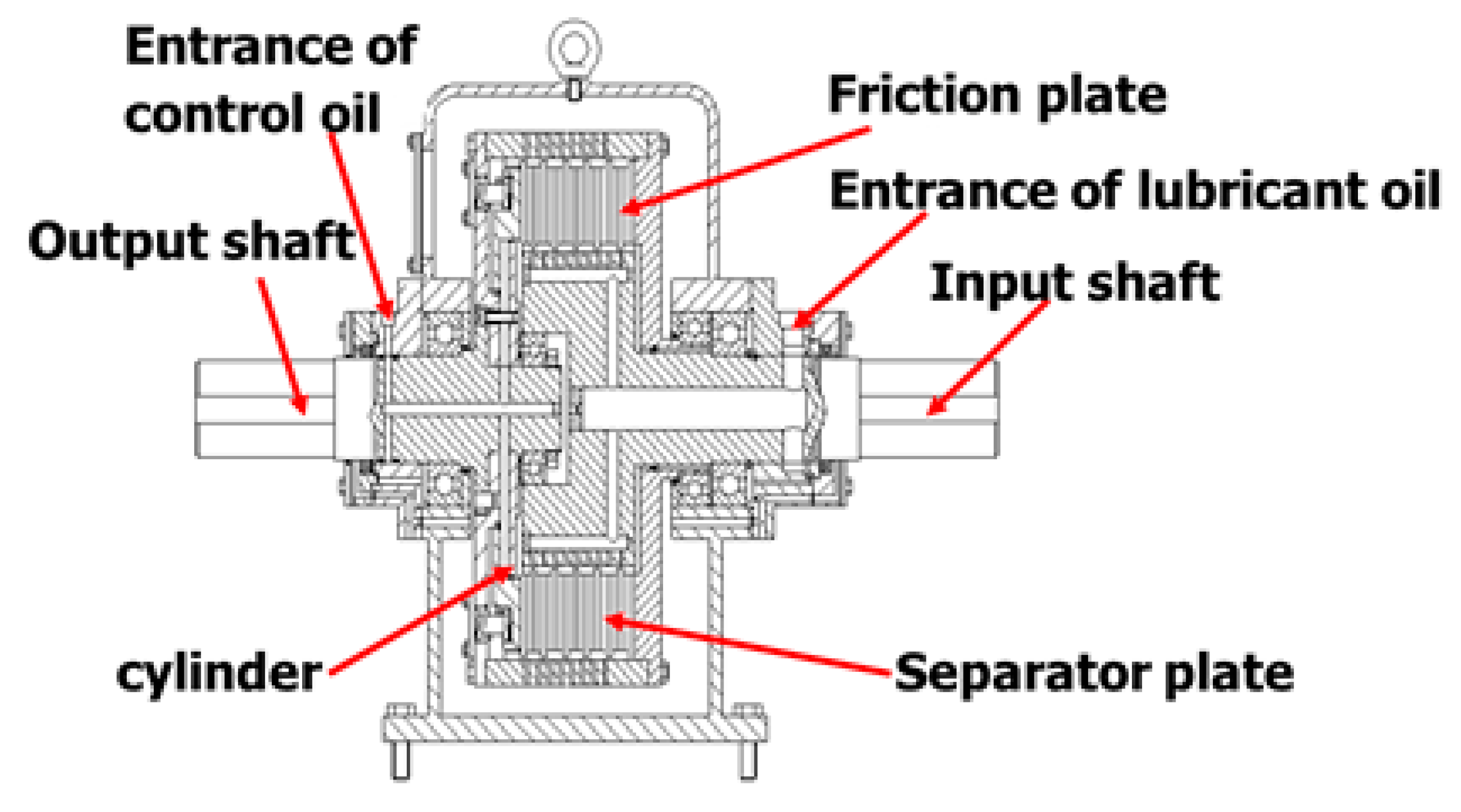
As shown in Figure 1, HVC is made up primarily of the input shaft, friction plate, separator plate, cylinder, output shaft, etc. Its work principle is as follows.
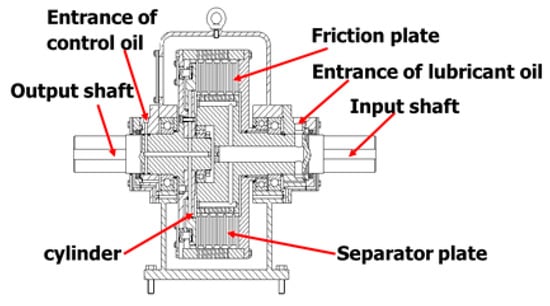
Figure 1.
Schematic diagram of hydro-viscous clutch.
Lubricant oil passes through the oil entrance of the input shaft to the gap between the friction plates and separator plates. On one hand, oil film can provide shear stress for HVC to transmit torque. On the other hand, it can take the heat away. Control oil passes through the control oil inlet channel to the cylinder chamber. By regulating the control oil pressure, the clearance between plates can be changed, so a different torque can be obtained and the torque formula can be derived from Newton inner friction law [1].
where T is the viscous torque, ω1 is the angular velocity of the friction plate, ω2 is the angular velocity of the separator plate, n is the number of plates, μ is the oil dynamic viscosity, r2 is the outer radius of the plate, r1 is the inner radius of the plate, and σ is the oil film thickness, m.
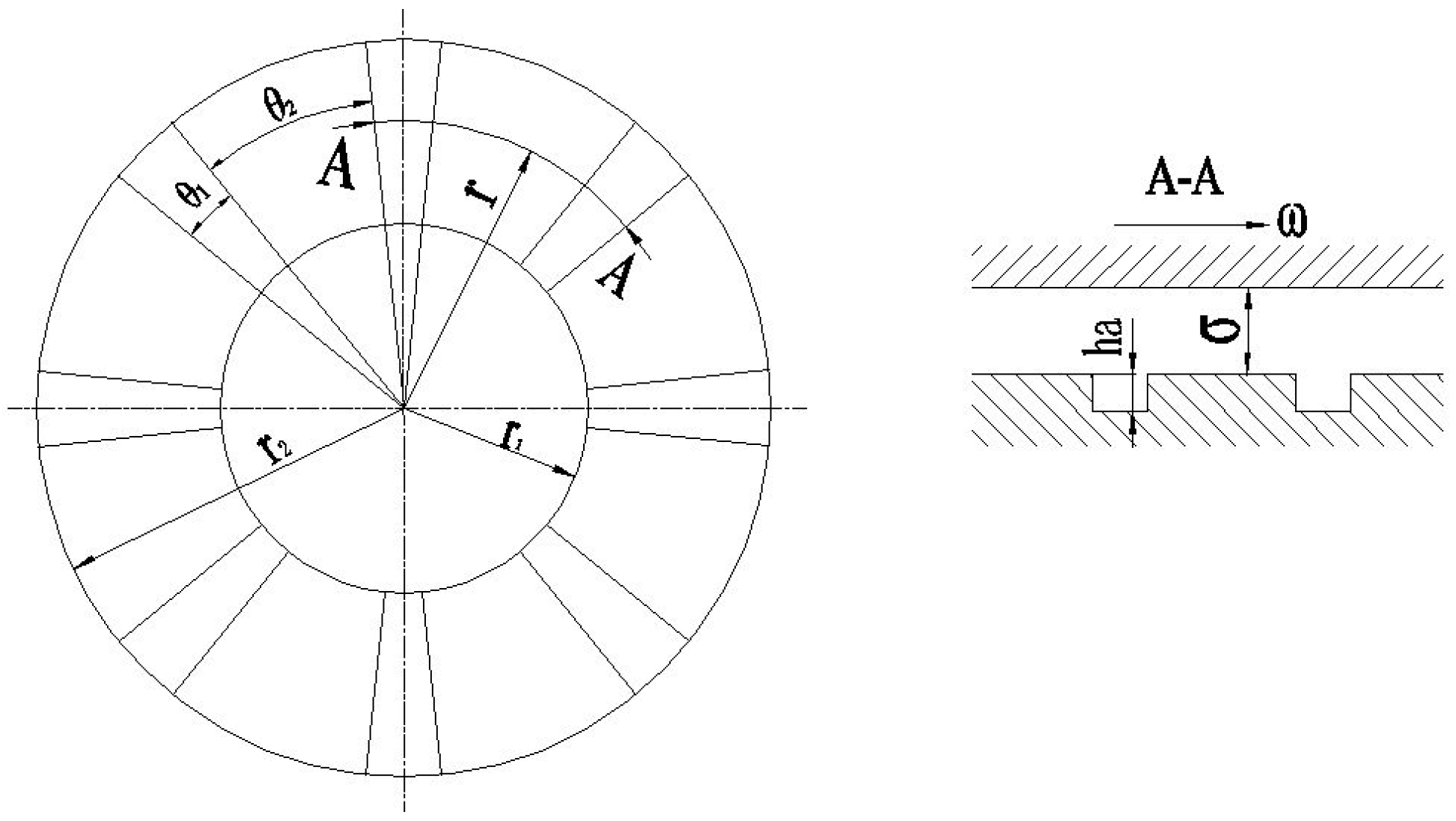
To avoid the thermal deformation of the plate induced by local contact, hydro-viscous plates’ surfaces are often grooved and the radial groove is the typical pattern that is used for hydro-viscous plates, as shown in Figure 2 (the following analysis is based on the plate with radial grooves). It can be deduced as:
where θ1 is the angle of the groove area, θ2 is the angle of the non-groove area, and ha is the groove depth.
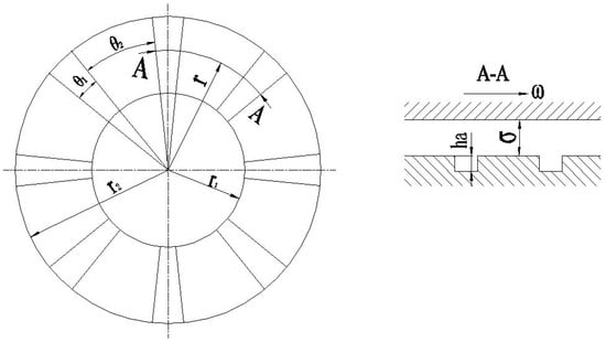
Figure 2.
Friction plate with radial grooves.
Form the above analysis, it can be seen that the viscous torque is usually obtained under the assumption that the oil film thickness is constant. In fact, HVC is composed of dozens of plates, and each clearance between plates may be quite different. Therefore, the viscous torque calculated by Equations (1) and (2) cannot precisely predict the true value.
3. Analysis of Oil Film Bearing Capacity
HVC is also called oil film clutch, since the oil film plays the most important role in transmitting viscous torque. The bearing capacity of oil film consists of the following parts [1]:
where Fd is the oil film bearing capacity, F1 is the bearing capacity of static pressure generated when lubricant oil flows through the gap between two still and parallel friction plates, F2 is the bearing capacity of centrifugal force when lubricating oil gets through two rotating friction plates, F3 is the squeezing force of friction plates when moving against each other, and F4 is the dynamic pressure bearing capacity caused by the groove on the surface of the friction plate.
Lubricating oil flows through the gap between two parallel friction plates and forms gap flow. The fundamental formula is as follows [16]:
Through the formula deduction, F1 can be described as:
where P is the lubricant oil pressure.
When lubricating oil flows through the gap between two rotating friction plates, the loss of pressure caused by centrifugal force leads to the centrifugal bearing capacity. It can be derived as [16]:
where ρ is the density of lubricating oil, and Δω is the angular velocity difference between the drive friction plate and driven separator plate.
When there is movement between friction plates, oil film thickness changes, which causes extrusion force, given by [16]:
The most important part of oil film bearing capacity in this paper is dynamic pressure bearing capacity, which is caused by grooves on the surface of the friction plate. Its expression is complex. For convenient analysis, the friction plate can be regarded as a tablet of length π(r1 + r2) and width (r2 − r1) [13], so the expression can be simplified to:
where z is the number of the groove, l1 is the groove width, and l2 is the step width.
To facilitate the analysis, assume:
so F4 can be described as:
4. Mechanical Analysis of the Friction Plate
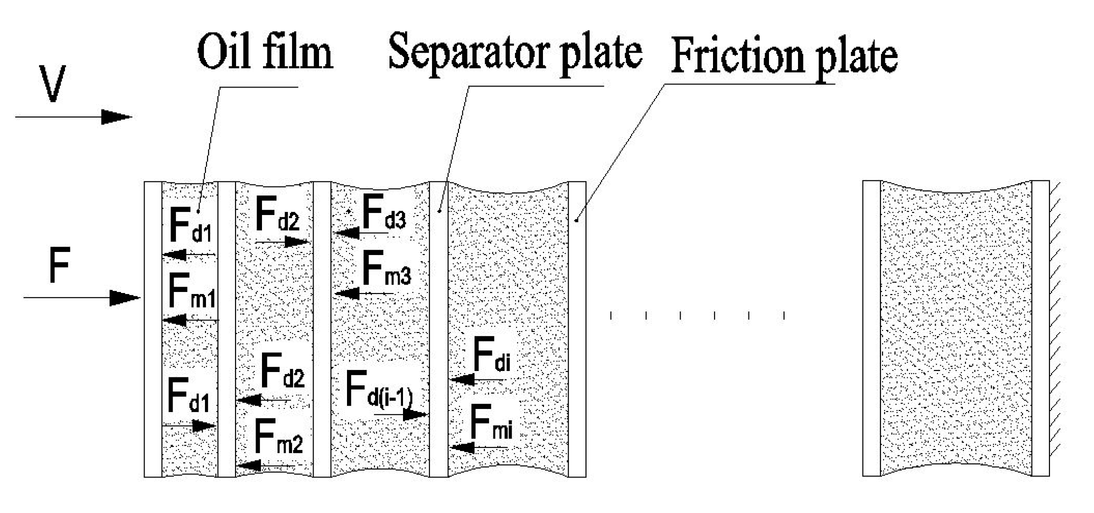
As shown in Figure 3, each friction plate reaches balance under the combination of the oil film bearing capacity and static friction.
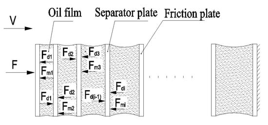
Figure 3.
Mechanical model of friction plates.
Oil film bearing capacity has been analyzed on the above, and the static friction force between the engagement of the friction plate is as follows:
Assume:
so Fmi can be described as:
where Fmi is the static friction force, f is the friction coefficient of plates, n is the number of oil films, and d is the effective diameter of the friction plate. It can be concluded that:
Assuming that HVC is in the state of stable speed, so Δω is constant, consequently each of F2 is equal; meanwhile, the oil film thickness between the friction plates reaches balance, so there is no relative movement between plates, so F3 is zero, and lubricant oil pressure between the friction plates is considered to be equal, so each of F1 is equal too.
From Equations (3)–(12), the distribution characteristic of oil film for HVC can finally be concluded:
From Equation (13), it is obvious that each oil film thickness is different unless K3 is zero, that is to say, there is no static friction force between the engagement of the friction plate. In practice, the static friction force is inevitable, so Equations (1) and (2) are not precise enough to predict the true viscous torque for HVC.
Based on Equation (13), a modified factor αi was introduced to revise the original torque formula.
Assume:
where σz is the total thickness of oil film, and is the average value of oil film thickness.
So, the revised torque formula can be described as:
In order to further study how K3/K1, K2, and ha influence the distribution characteristic of oil film thickness and the viscous torque, the following simulation is based on the practical parameters of HVC listed in Table 1.

Table 1.
Parameters of HVC.
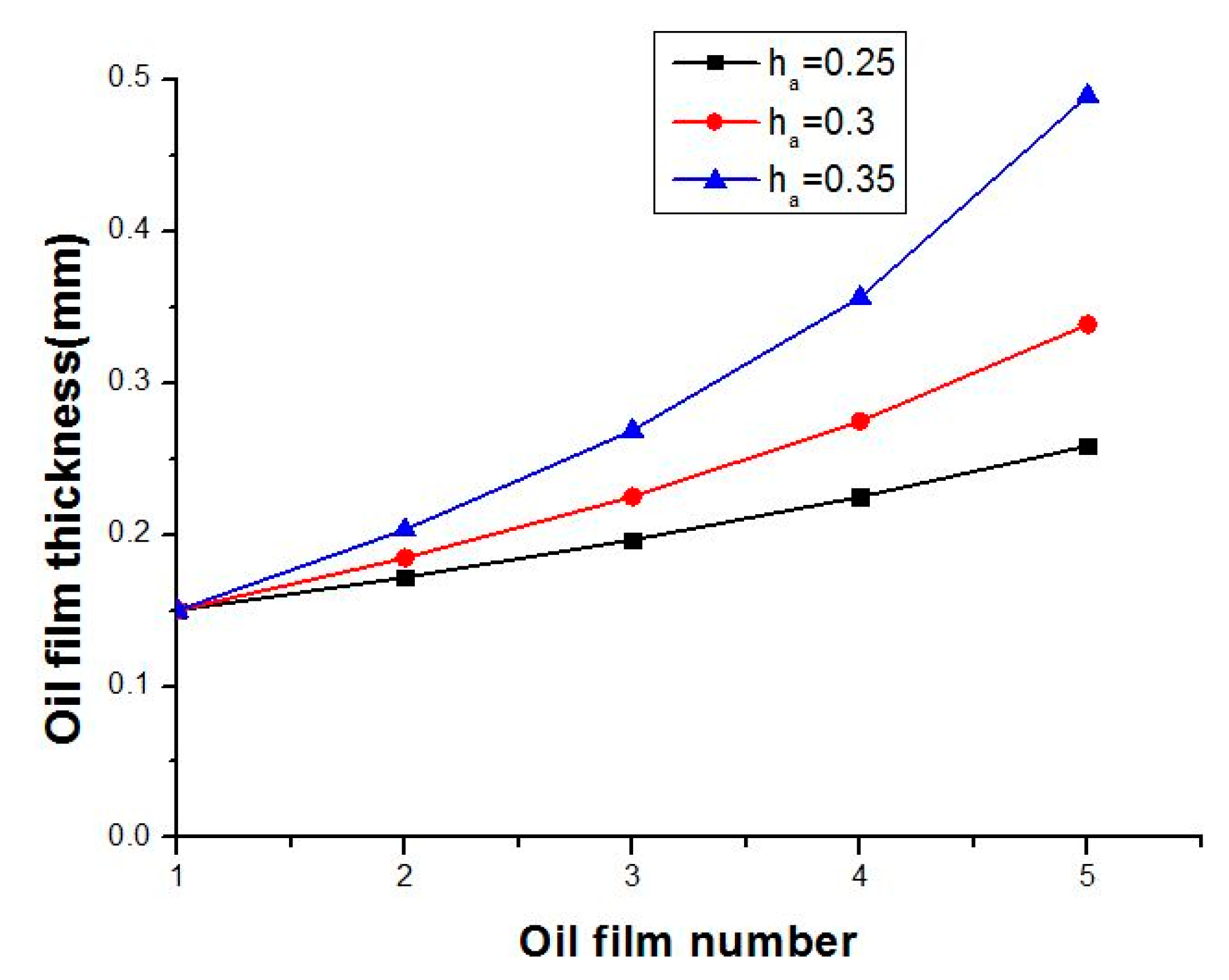
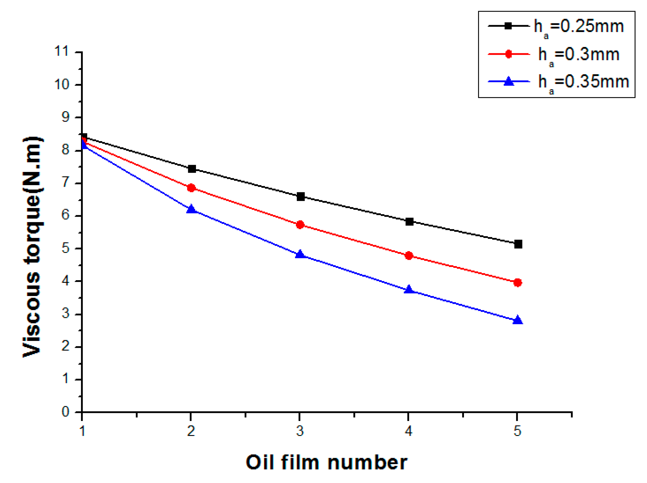
Under the situation of K2 = 2, K3/K1 = 0.1, given ha = 0.25, 0.3, 0.35, the relationship between viscous torque, oil film thickness, and the oil film number is shown in Figure 4 and Figure 5.
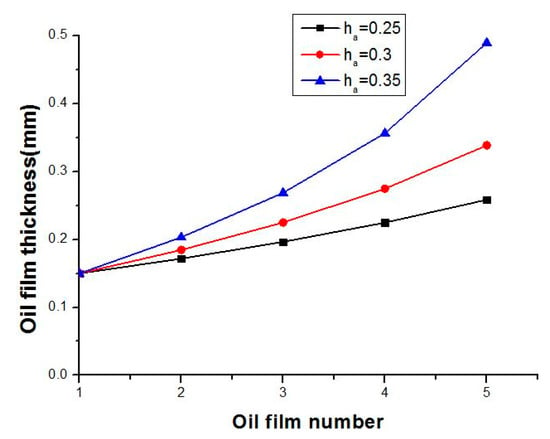
Figure 4.
Oil film thickness distribution with different ha.
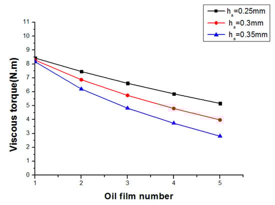
Figure 5.
Viscous torque distribution with different ha.
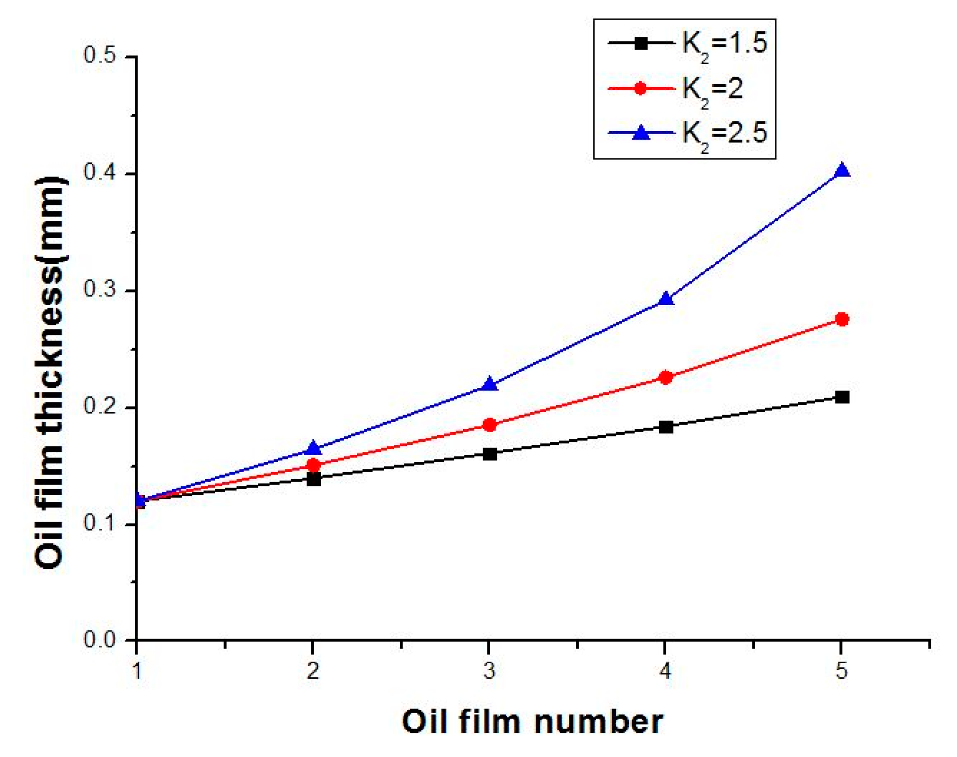
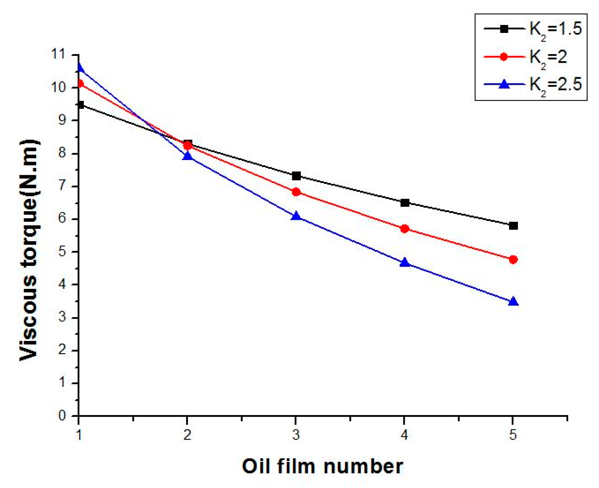
Under the situation of ha = 0.3, K3/K1 = 0.1, given K2 = 1.5, 2, 2.5, the relationship between viscous torque, oil film thickness, and the oil film number is shown in Figure 6 and Figure 7.
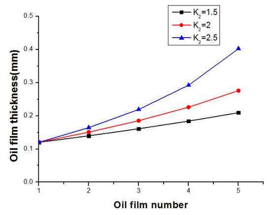
Figure 6.
Oil film thickness distribution with different K2.
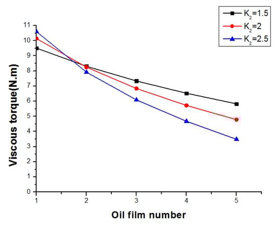
Figure 7.
Viscous torque distribution with different K2.
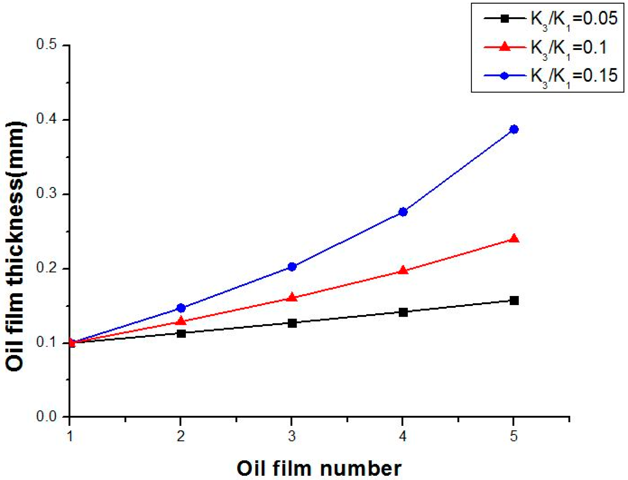
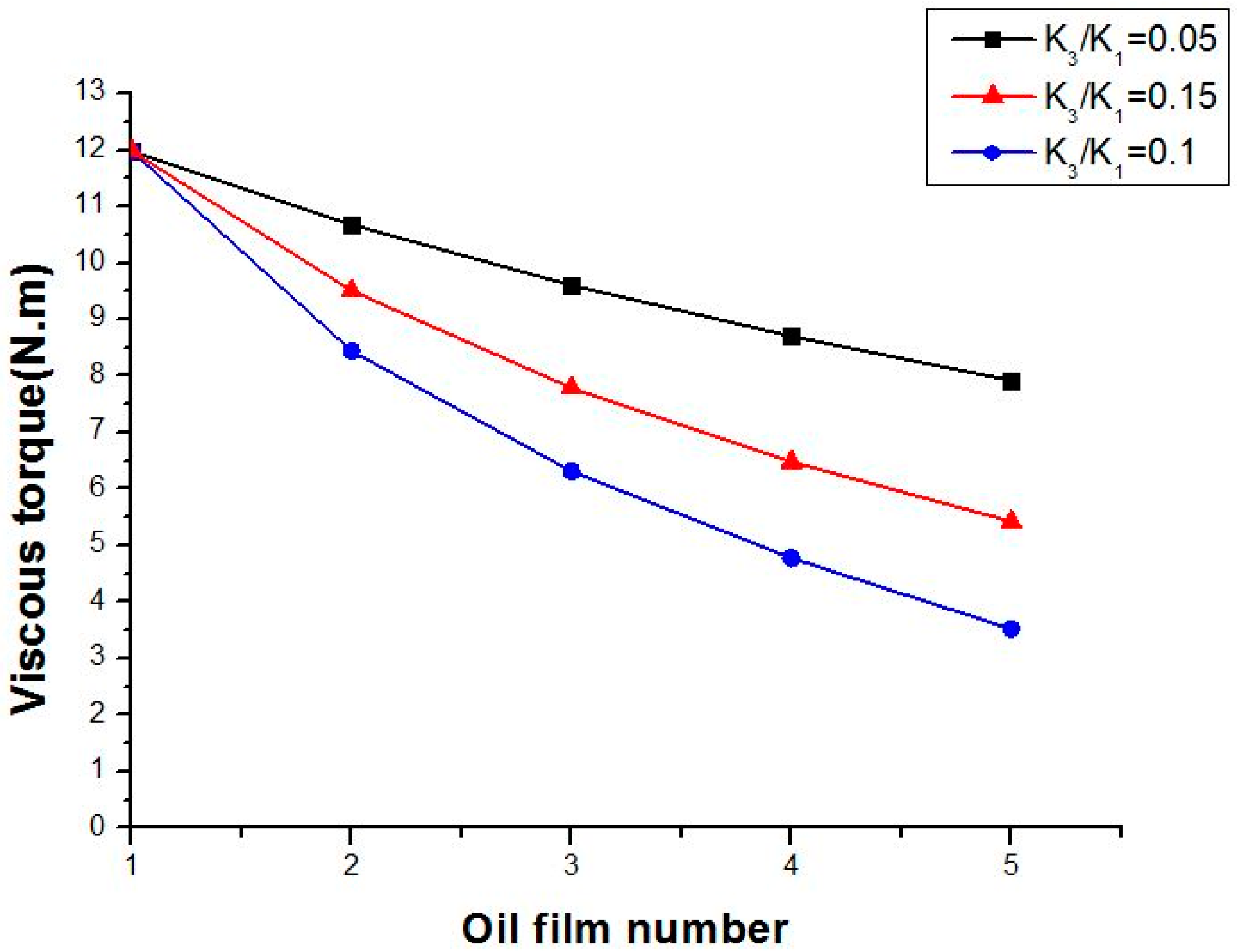
Under the situation of ha = 0.3, K2 = 2, given K3/K1 = 0.05, 0.1, 0.15, the relationship between viscous torque, oil film thickness, and the oil film number is shown in Figure 8 and Figure 9.
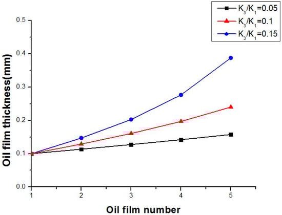
Figure 8.
Oil film thickness distribution with different K3/K1.
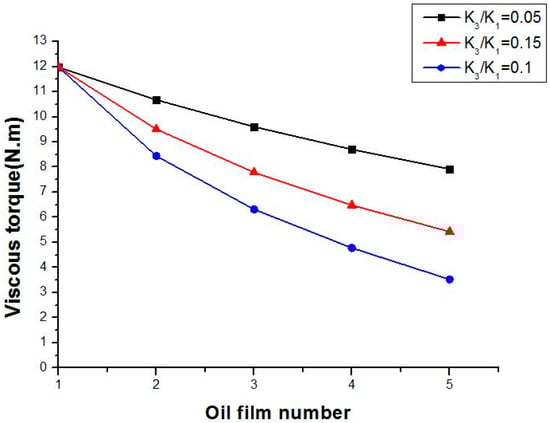
Figure 9.
Viscous torque distribution with different K3/K1.
From Figure 4, Figure 5, Figure 6, Figure 7, Figure 8 and Figure 9, it can be seen that oil film thickness becomes greater as the oil film number increases, while viscous torque becomes lower. Moreover, each oil film thickness and viscous torque becomes more different with the increase in the coefficient K2, ha, and K3/K1. Comparing the above three Figure 4, Figure 6 and Figure 8, the coefficient K3/K1 plays a more important role in determining the distribution of oil film thickness and viscous torque for HVC. That is to say, among the factors of the groove depth, angular ratio of groove/non-groove, and static friction force, the static friction force is the key factor influencing the distribution of oil film thickness, which should be taken into account to calculate the overall viscous torque of HVC.
5. Experimental Apparatus and Results
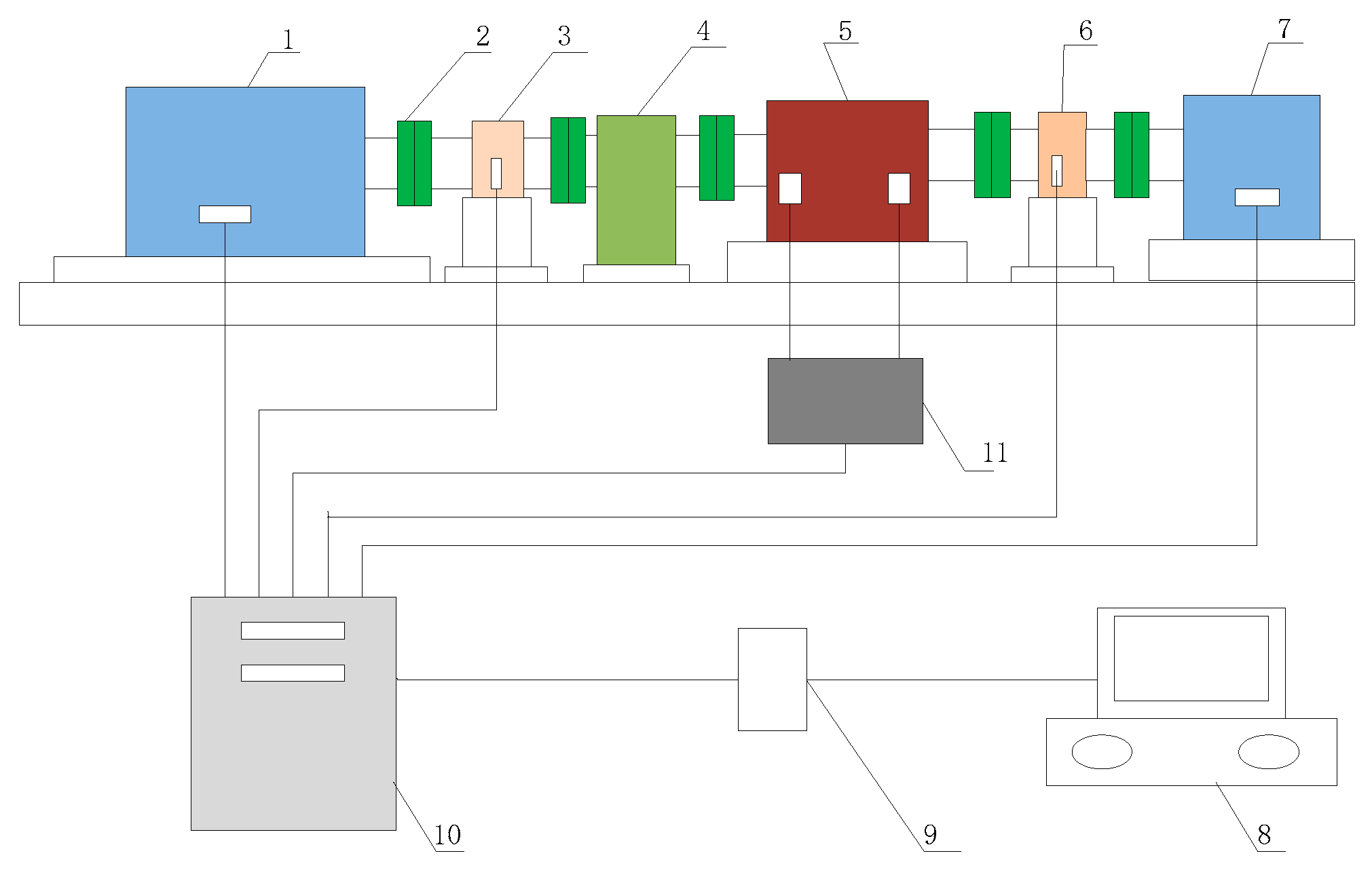
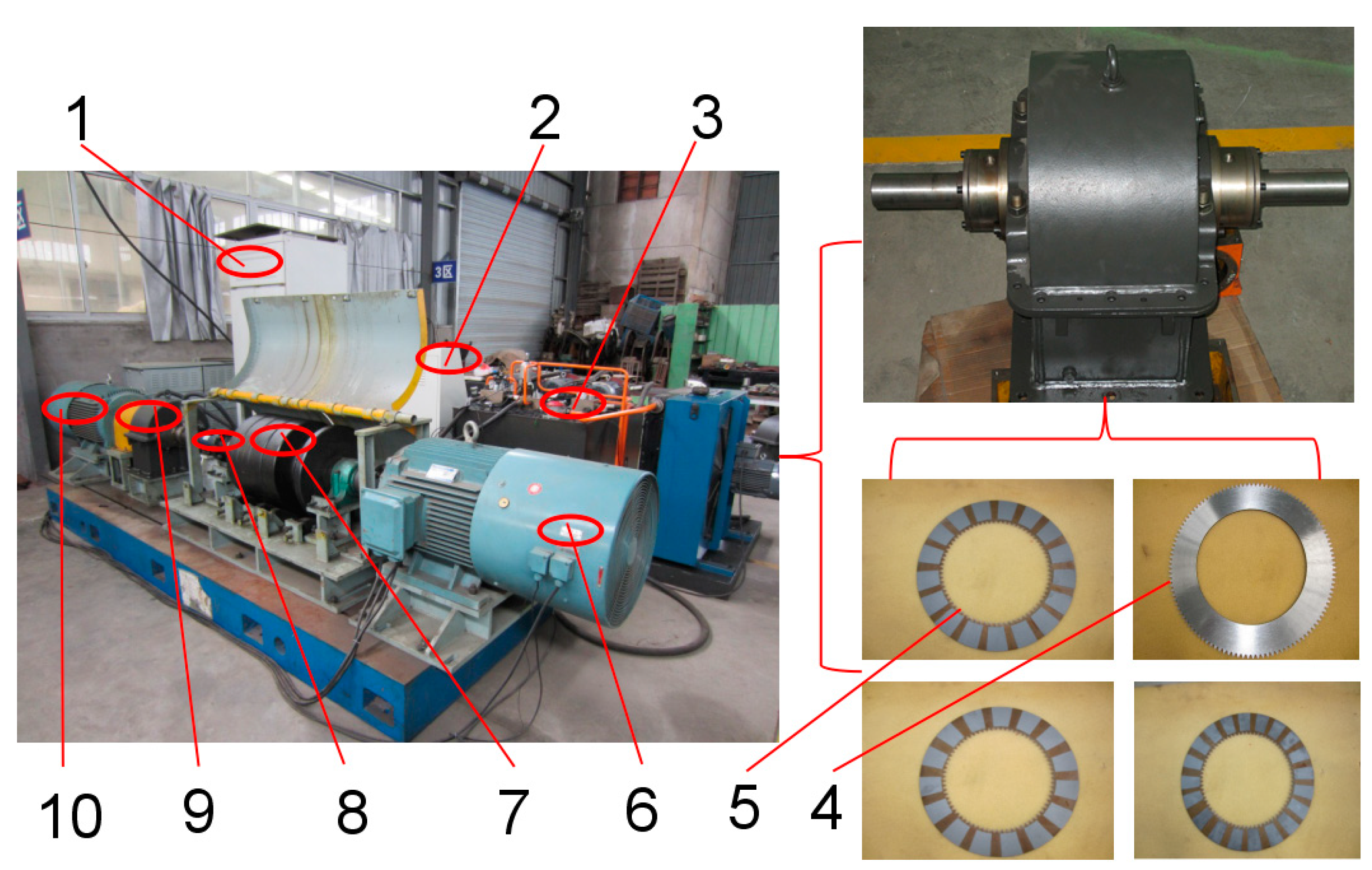
The hydro-viscous clutch test rig is illustrated in Figure 10 and Figure 11. In this system, the drive part is a variable frequency motor to achieve different input speeds for HVC and the loading part is an electric dynamometer to provide precise torque. The hydraulic power unit can provide the needed lubricant oil and control oil for HVC. The flywheel set is used to test the dynamic performance of HVC. With LABVIEW software and PCI 1723 data acquisition card, the industrial control computer sends out command signals to the drive motor, loading motor, and hydraulic power unit. After receiving command signals, the hydro-viscous clutch can work at different input speeds, loading torque, control oil pressure, lubricant oil pressure, and flux.

Figure 10.
Schematic diagram of the HVC test rig. 1—drive motor; 2—coupling; 3,6—torque and speed sensor; 4—flywheel set; 5—HVC; 7—loading motor; 8—computer; 9—signal control cabinet; 10—data acquisition card; 11—hydraulic power unit.
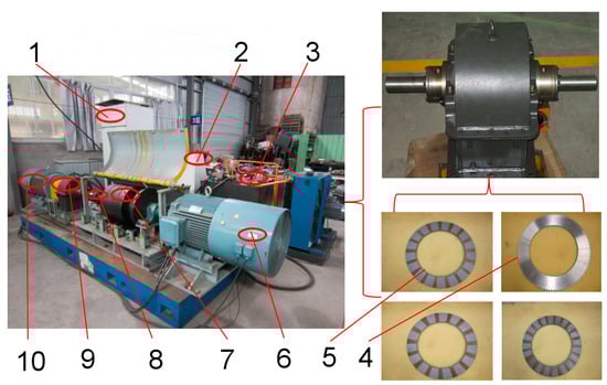
Figure 11.
Photos of the HVC and test rig. 1—signal control cabinet; 2—computer operation cabinet; 3—hydraulic power unit; 4— friction plate, 5—separator plate with different grooves, 6—drive motor; 7—flywheel set; 8—torque and speed sensor; 9—HVC; 10—loading motor.
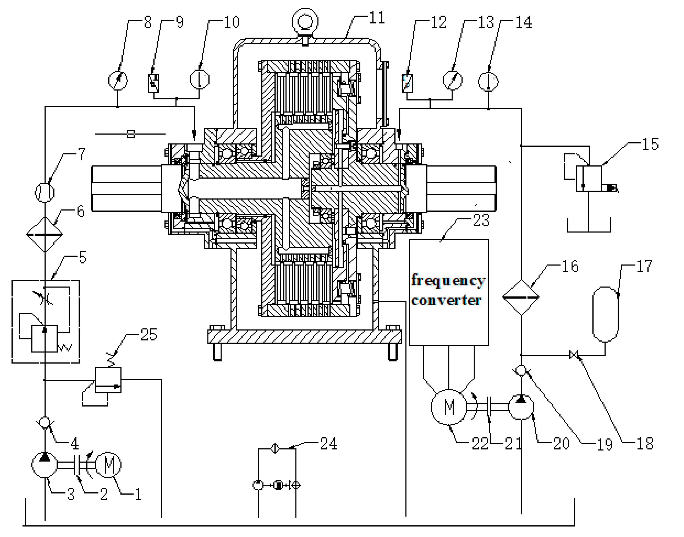
Figure 12 illustrates the schematic diagram of the hydraulic system for HVC. In this part, the whole system can be divided into control oil circuit and lubricant oil circuit. The control oil pump and lubricant oil pump can respectively provide the working fluid for HVC. The flow speed control valve is used to achieve different lubricant oil flow and pressure. The accumulator can absorb the pressure fluctuation under high frequency. The proportional relief valve is used to realize different control oil pressure. The frequency converter is used to achieve low pressure (0.05–0.5 MPa) because of the dead zone pressure of the proportional relief valve. In addition, some manometers, flowmeters, and thermometers are mounted to measure the local pressure, flux, and temperature. Related parameters are acquired by sensors and their curves are finally displayed on the screen of a computer. Table 2 shows the main parameters of the whole test rig.
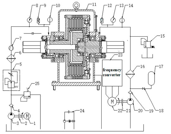
Figure 12.
Diagram of the hydraulic system for HVC. 1,22—oil pump motor; 2,21—coupling; 3—lubricant oil pump; 4,19—check valve; 5—flow speed control valve; 6,16—fine filter; 7—flowmeter; 8,13—manometer; 9,12—Pressure sensor; 10,14—thermometer; 11—hydro—viscous clutch; 15—proportional relief valve; 17—energy accumulator; 18—stop valve; 20—control oil pump; 23—frenquency converter; 24—air cooling circuit; 25—safety valve.
Table 2.
Main parameters of the test rig.
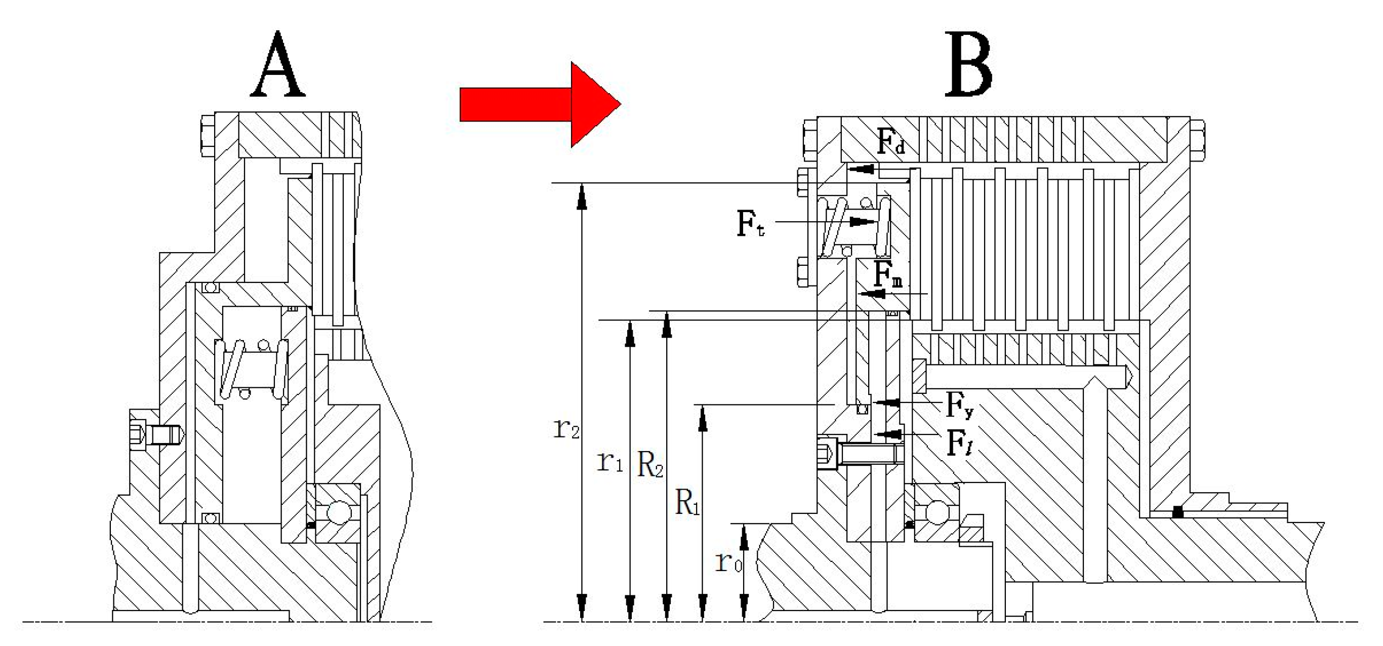
What should be explained in advance is that there are no displacement sensors in HVC to measure each clearance between friction plates. In fact, it is very difficult to accurately measure each oil film thickness of HVC, since the clearance between friction plates is so small. However, if the structure of HVC is improved from the ordinary type to the synchronous type (as is shown in Figure 13) [5,6], the oil film thickness can be indirectly calculated according to the piston force analysis.
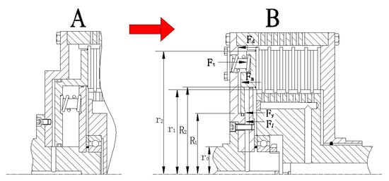
Figure 13.
Comparison of two different types of HVC.
Figure 13 also shows the force modeling of the piston in the synchronous type of HVC. The piston reaches its balance under the resultant force of the spring force, cylinder pressure, centrifugal pressure of the cylinder, static friction force between the engagement of the friction plate, and bearing capacity of the first oil film. It can be described as:
where Ft is the force of the pressure spring, xz is the displacement of the spring, x0 is the precompressed spring length, k is the stiffness of the pressure spring, N is the number of pressure springs, Fy is the control oil force, p is the control oil pressure, R2 is the outer radius of the cylinder, R1 is the inner radius of the cylinder, m, and Fl is the centrifugal force caused by the rotation of the cylinder.
Because the related parameters (including k, x0, N, Fy, Fl, etc.) are clear, and the number of unknown variables σi is equal to the number of equations, each oil film thickness is uniquely determined. However, there is no definite relationship between xz and σi for the ordinary type of HVC, because the initial clearance between each friction plate is randomly distributed without the control oil pressure.
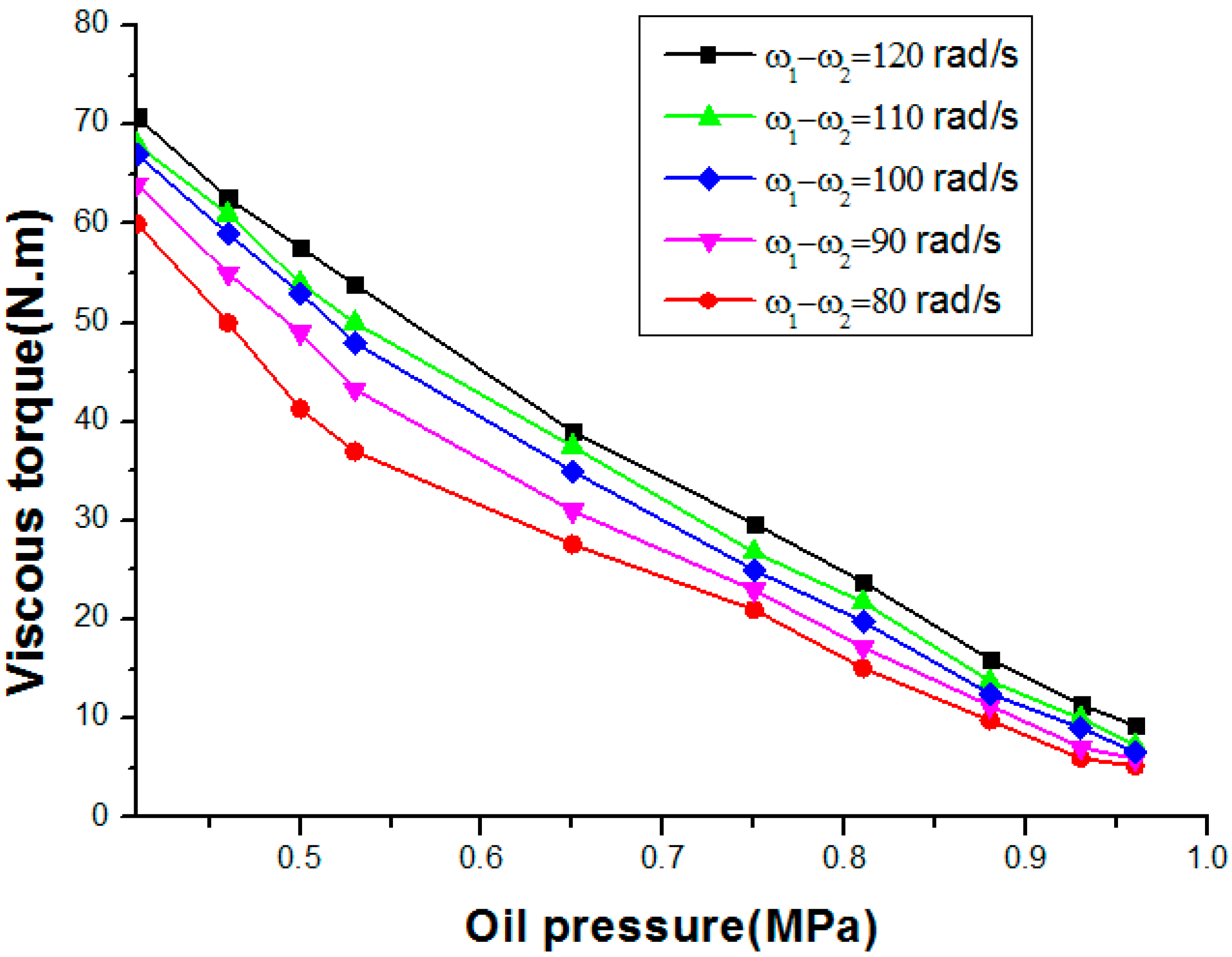
Finally, the overall torque characteristic of HVC and the experimental data related to the overall viscous torque were respectively obtained as shown in Figure 14 and Table 3.
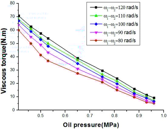
Figure 14.
Overall torque characteristic of HVC.
Table 3.
Experimental data related to the overall viscous torque.
From Figure 14, it can be concluded that the decrease in viscous torque with the increase in control oil pressure increases with the increase in Δω, which conforms to the law of hydro-viscous drive well. From Table 3, it can be summarized that there is a large relative error (from the minimum 25.4% to the maximum 40.2%) by using the original formula to calculate the torque without considering the condition that each clearance of friction plates is different. In addition, with the increase in coefficient K2, ha, and K3/K1, the relative torque error becomes larger, since the difference in oil film thickness and viscous torque becomes greater. By contrast, the torque calculated by the revised formula is much closer to the experimental results, the minimum relative error is reduced to 2.8%, and the average relative error is 5.4%. Furthermore, with the increase in coefficient K2, ha, and K3/K1, the relative torque error becomes smaller, since the revised torque formula can compensate the uneven distribution effect of oil film thickness. Therefore, it supports the conclusion that the revised torque formula is more accurate compared to the original one.
6. Conclusions
A hydro-viscous clutch is composed of multi-friction plates. When it is in the stable speed regulation operation condition, it is generally considered that the oil film thickness between the friction plates is equal (the existing torque formula for HVC is based on this assumption), which is inconsistent with the actual situation. In order to obtain a more accurate torque formula for HVC, this paper has carried out research work from both theoretical and experimental aspects, and the conclusions are as follows:
- (1)
- A new revised torque formula for hydro-viscous drive is proposed through taking into account the condition that each clearance of friction plates is different.
- (2)
- Theoretical analysis indicates that static friction force between the engagement of the friction plate can result in the back oil film thickness being greater than the front one, and the oil film thickness become greater with the increase in the coefficient K2, ha, and K3/K1.
- (3)
- A new structure of HVC is proposed to validate the related torque characteristics of HVC. The experimental results show that there are large relative errors (from the minimum 25.4% to the maximum 40.2%) by using the original formula to calculate the torque. Inversely, the overall viscous torque obtained by the revised formula can predict the true value more precisely with the increase in coefficient K2, ha, and K3/K1, and the minimum relative error can reduce to 2.8%, which proves that the revised model is more accurate than the original one.
Author Contributions
Writing—original draft preparation, X.L.; writing—review and editing, S.Y.; supervision, D.H.; project administration, G.G. All authors have read and agreed to the published version of the manuscript.
Funding
This research received no external funding.
Data Availability Statement
The data used to support the findings of this study are available from the corresponding author upon request.
Acknowledgments
This work was supported by the Natural Science Foundation of Hunan Province of China (2021JJ30378), the Research Foundation of Education Bureau of Hunan Province of China (20B325), and the Open Research Fund of State Key Laboratory of High Performance Complex Manufacturing, Central South University (Kfkt2019-13).
Conflicts of Interest
The authors declare no conflict of interest.
References
- Wei, C.G.; Zhao, J.X. Hydro-Viscous Transmission Technology; National Defence Industry Press: Beijing, China, 1996; pp. 51–80. [Google Scholar]
- Zhang, Y.D.; Zhang, Q.X. Investigation on start behavior of hydro-viscous transmission. J. Beijing Univ. Aeronaut. Astronaut. 2002, 28, 578–780. [Google Scholar]
- Liao, X.P. Research on the Engineering Application of HVC. Master’s Thesis, Xiangtan University, Xiangtan, China, 2008. [Google Scholar]
- Gong, G.F.; Wang, F.; Qin, Y.F.; Zhang, Y.K.; Sun, C.C.; Yang, H.Y. The design of low cost valve-and-pump compounded pressure control system for the hydro viscous clutch. Mechatronics 2020, 65, 102310. [Google Scholar] [CrossRef]
- Xie, H.B.; Gong, H.S.; Yang, H.Y. Improving the extricating performance of TBM cutter-head driving system with hydro-viscous clutch[C]. In Proceedings of the MESA 2016—12th IEEE/ASME International Conference on Mechatronic and Embedded Systems and Applications—Conference Proceedings, Auckland, New Zealand, 29–31 August 2016. [Google Scholar] [CrossRef]
- Chen, P.; Chen, J.H.; Hu, Z.Q. Software-in-the-Loop combined Reinforcement learning method for Dynamic Response Analysis of FOWTs. Front. Mar. Sci. 2021, 7, 1–17. [Google Scholar] [CrossRef]
- Mahdi, I.; Seyede, F.G. Partially-Observed Discrete Dynamical Systems. In Proceedings of the 2021 American Control Conference (ACC), New Orleans, LA, USA, 26–28 May 2021. [Google Scholar]
- Xie, F.W.; Hou, Y.F.; Yang, P. Drive characteristics of viscous oil film considering temperature effect. ASME J. Fluids Eng. 2011, 133, 044502. [Google Scholar] [CrossRef]
- Marklund, P.; Mäki, R.; Larsson, R.; Höglund, E.; Khonsari, M.; Jang, J. Thermal influence on torque transfer of wet clutches in limited slip differential applications. Tribol. Int. 2007, 40, 876–884. [Google Scholar] [CrossRef]
- Xie, F.W.; Zhang, L.Q.; Wang, H. Effect of oil film temperature on hydro-viscous drive characteristics. In Proceedings of the 2011 International Conference on System Science, Engineering Design and Manufacturing Informatization, Guiyang, China, 22–23 October 2011; Volume 2, pp. 246–249. [Google Scholar]
- Meng, Q.R.; Hou, Y.F. Effect of working oil temperature rise on hydro-viscous drive speed regulating start. Trans. Chin. Soc. Agric. Mach. 2010, 41, 214–218. [Google Scholar]
- Liao, X.P.; Gong, G.F.; Zhou, T.V.; Wang, H. Dynamic performance of hydro-viscous drive clutch with double-piston. Trans. Chin. Soc. Agric. Mach. 2014, 7, 1–6. [Google Scholar]
- Gong, G.F.; Liao, X.P.; Liu, Y.; Yang, H.Y. A New Kind of Hydro-Viscous Clutch. CHN Patent No. 201210389516.0, 12 November 2014. [Google Scholar]
- Gong, G.F.; Liao, X.P.; Liu, Y.; Yang, H.Y. A New Kind of Speed Regulating Device. CHN Patent No. 201210389501.4, 2 November 2015. [Google Scholar]
- Liao, X.P.; Gong, G.F.; Zhou, T.V.; Peng, X.B. Design and characteristic of lubricating oil chamber of hydro-viscous drive clutch. J. Drain. Irrig. Mach. Eng. 2014, 12, 1062–1067. [Google Scholar]
- Chen, N. Theoretical and Application Researches on Hydro Viscous Drive. Ph.D. Thesis, Zhejiang University, Zhejiang, China, 2003. [Google Scholar]
- Meng, Q.R. Study on Hydro-Viscous Drive Speed Regulating Start and Control Technology. Master’s Thesis, University of Mining and Technology, Xuzhou, China, 2011. [Google Scholar]
- Huang, J.H. Research on the Mechanism of Fluid Power Transmission by Shear Stress in Hydro-Viscous Drive. Ph.D. Thesis, Zhejiang University, Hangzhou, China, 2011. [Google Scholar]
- Huang, J.H.; Fan, Y.R.; Qiu, M.X.; Fang, W.M. Effect of groove on behavior of flow between hydro-viscous drive plates. J. Cent. South Univ. Technol. 2012, 2, 347–356. [Google Scholar] [CrossRef]
- Cui, H.W.; Yao, S.W.; Yan, Q.D.; Feng, S.S.; Liu, Q. Mathematical Model and Experiment Validation of Fluid Torque by Shear Stress under Influence of Fluid Temperature in Hydro-viscous Clutch. Chin. J. Mech. Eng. 2014, 1, 32–40. [Google Scholar] [CrossRef]
- Yao, S.W.; Cui, H.W.; Wang, X.P.; Feng, S.S. Numerical film torque modeling of friction pair in hydro-viscous clutch. J. Beijing Inst. Technol. 2014, 2, 165–171. [Google Scholar]
- Yuan, Y.Q.; Liu, E.A.; Hill, J.; Zou, Q. An improved hydrodynamic model for open wet transmission clutches. ASME J. Fluids Eng. 2007, 129, 333–337. [Google Scholar] [CrossRef]
- Hu, J.B.; Peng, Z.X.; Yuan, S.H. Drag torque prediction model for the wet clutches. Chin. J. Mech. Eng. 2009, 22, 238–243. [Google Scholar] [CrossRef]
- Razzaque, M.M.; Kato, T. Effects of a groove on the behavior of a squeeze film between a grooved and a plain rotating annular disk. ASME J. Tribol. 1999, 121, 808–815. [Google Scholar] [CrossRef]
- Phale, C.R.; Cho, J.; Schultz, W.W.; Ceccio, S.L.; Yoshiokat Hiraki, H. Modeling and parametric study of torque in open clutch plates. ASME J. Tribol. 2006, 128, 422–430. [Google Scholar]
- Huang, J.H.; Qiu, M.X.; Liao, L.L.; Fu, L.J. Numerical simulation of flow field between frictional pairs in hydro viscous drive surface. Chin. J. Mech. Eng. 2008, 21, 72–75. [Google Scholar] [CrossRef]
Publisher’s Note: MDPI stays neutral with regard to jurisdictional claims in published maps and institutional affiliations. |
© 2021 by the authors. Licensee MDPI, Basel, Switzerland. This article is an open access article distributed under the terms and conditions of the Creative Commons Attribution (CC BY) license (https://creativecommons.org/licenses/by/4.0/).