Article

Control Performance Improvement of Hydro-Viscous Clutch Based on Fuzzy-PID Controller

1
College of Mechanical Engineering, Hunan University of Humanities, Science and Technology, Loudi 417000, China
2
State Key Laboratory of High Performance Complex Manufacturing, Central South University, Changsha 410083, China
3
State Key Laboratory of Fluid Power Transmission and Control, Zhejiang University, Hangzhou 310027, China
4
Department of Mechanical Engineering, Shantou University, Shantou 515063, China
*
Author to whom correspondence should be addressed.
Energies 2021, 14(24), 8282; https://doi.org/10.3390/en14248282
Submission received: 12 November 2021 / Revised: 2 December 2021 / Accepted: 6 December 2021 / Published: 9 December 2021
(This article belongs to the Special Issue New Challenges in Electrohydraulic Control System and Energy Saving)

Abstract

:
As a rotational speed controller, a hydro-viscous clutch (HVC) is usually used in the constant pressure water supply system to maintain the needed water pressure constant. However, when the hydro-viscous clutch is working, it often suffers from the problem of output rotational speed fluctuation since the spool of proportional relief valve can easily get stuck. Consequently, water pressure will fluctuate too. A special pump control system of HVC was proposed based on the Fuzzy-PID controller for the purpose of reducing the fluctuation rate. The MATLAB simulation was carried out according to the mathematical model and the results show that the Fuzzy-PID control strategy is superior to traditional PID control. The corresponding experiment was performed and the result indicate that through applying the Fuzzy-PID controller based pump control system, the rotational output speed fluctuation of HVC can be inhibited from ±60π to ±6π rad/min, and the water pressure fluctuation is dropped from ±0.1 to ±0.002 MPa.

1. Introduction

Hydro viscous drive (HVD) is a new technology of hydrodynamic transmission developed in the 1970s. It relies on the viscosity of fluid to transmit power through the action of fluid shear force. In some heavy pumps industrial fields in waterworks, since its power is directly proportional to the cube of its rotational speed, a hydro-viscous clutch can save a lot of energy by changing the oil film thickness between two friction disks under different control oil pressure to achieve different output rotational speed [1,2].
In general, valves are used to control oil pressure for HVC because of their excellent dynamic performance. For example, a hydraulic serve valve was used to control pressure for HVC using the twin disk corporation (in the commonwealth of Pennsylvania of USA). The “Ω” valve was proposed by the Niigata Coveter Corporation (in the Niigata of Japan) to regulate system pressure for HVC. The proportional relief valve was chosen by Professor Wei to achieve different pressure for HVC [3,4]. However, valves can easily get stuck and lead to output rotational speed fluctuation. More researchers have focused on the stability of HVC. Mikael et al. [5] researched the engagement of the clutch, and the results showed that the output speed of the clutch can be smoothed through optimizing the controlling method of the propulsion cylinder pressure. Huang et al. [6] analyzed the influences of a small ripple of control oil pressure on the output speed of HVC, and concluded that HVC can work stably when the frequency of the control oil’s pressure ripple is higher than 60 Hz and the peak is less than 0.05 MPa. Chen et al. [7] studied the soft start characteristic of HVD, and found that the poor pressure stability of the proportional relief valve under low flow and oil pressure conditions is the reason for the fluctuation of output speed of the hydro-viscous clutch. Furthermore, a special speed regulating valve was developed to improve the start-up steadiness of HVC.
All the above mentioned studies on the stability of HVC are based on the valve control method. However, the pump control system is also widely used in various industrial applications for achieving high energy efficiency and high reliability. FJTE, Ferreira et al. [8] compared the energy savings between a pump control system and a valve control system and pointed out that the reduction of life-circle cost can reach over 25% by using a variable speed pump-controlled system. Nicola et al. [9] studied the energy-saving performance in requirement-oriented irrigation systems supplied by variable speed pumps and concluded that through matching the displacement and the pressure needed by the network characteristic curve, energy savings of about 27–35% may be achieved for the irrigation stations. Mao et al. [10] proposed a hydraulic pump controlled system driven by a variable speed AC servo motor in a hydraulic injection molding machine and the results showed that it can perform good response and robustness against the external disturbance.
In order to improve the pump control system’s performance while keeping its high energy savings, some researchers combined the valve control and pump control methods [11]. Zhao et al. [12] put forward a new control mechanism of valve-pump paralled variable structure control which could be accommodated between valve control and pump control to meet the control requirements, and concluded that the overall characteristic of the variable speed pump control system could be significantly improved. Gong et al. [13] proposed a compounded control system (valve control and pump control) for HVC, the pressure control range is increased by 38% under the low pressure condition.
To further improve the control characteristics of pump control system while simplifying the system, more researchers have focused on the controller design method [14,15,16]. Jahmeerbacus et al. [17] presented a flux control system of an AC motor driven pump based on the fuzzy logic strategy. Simulation results show that the fuzzy logic scheme has good tracking ability under strong disturbance. Kastrevc et al. [18] employed a Fuzzy-PID controller to improve the pressure control performance of the pump control system, experiments verified the apparent robustness of Fuzzy-PID controller.
All the above literature gives us a revelation that the performance of the pump control system with appropriate control algorithm is comparable to that of the valve control system. Consequently, a new pump control system for the HVC will be proposed to overcome the speed fluctuation in this work. Furthermore, in order to significantly improve the control performance of the new pump control system, a Fuzzy-PID controller will be established based on its theoretical model. Additionally, performances of both methods such as the tracking ability, overshoot, adjustment time and anti-interference ability will be compared and analyzed. Finally, an industrial experiment will be carried out to verify the simulation results.

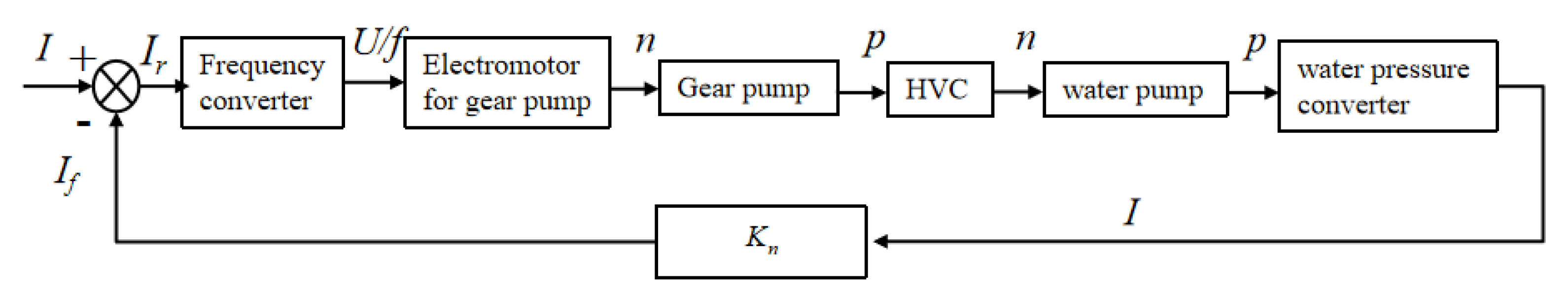
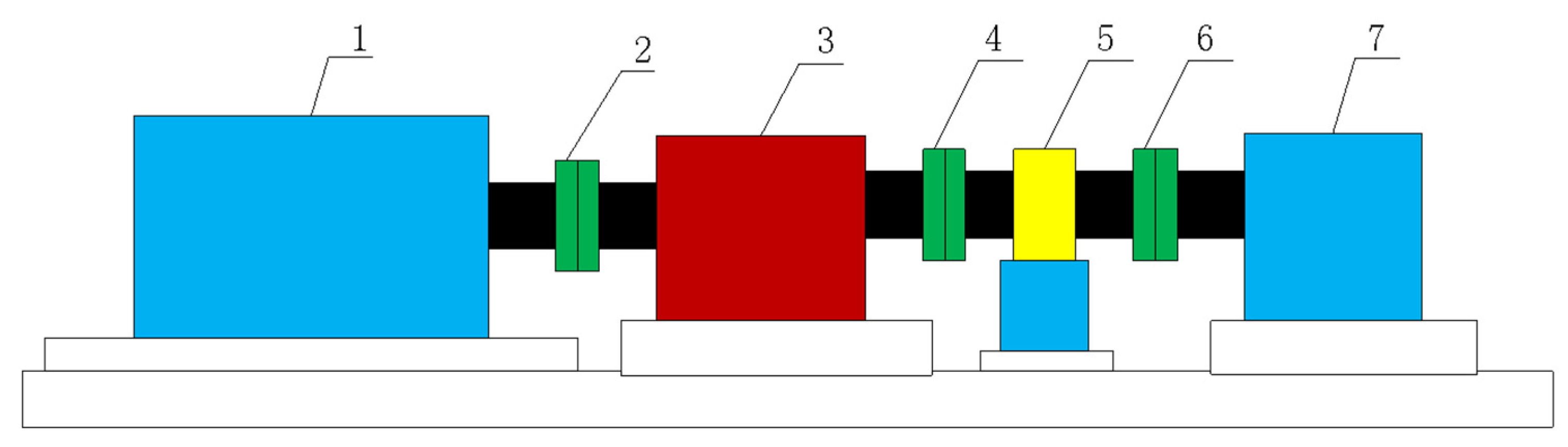
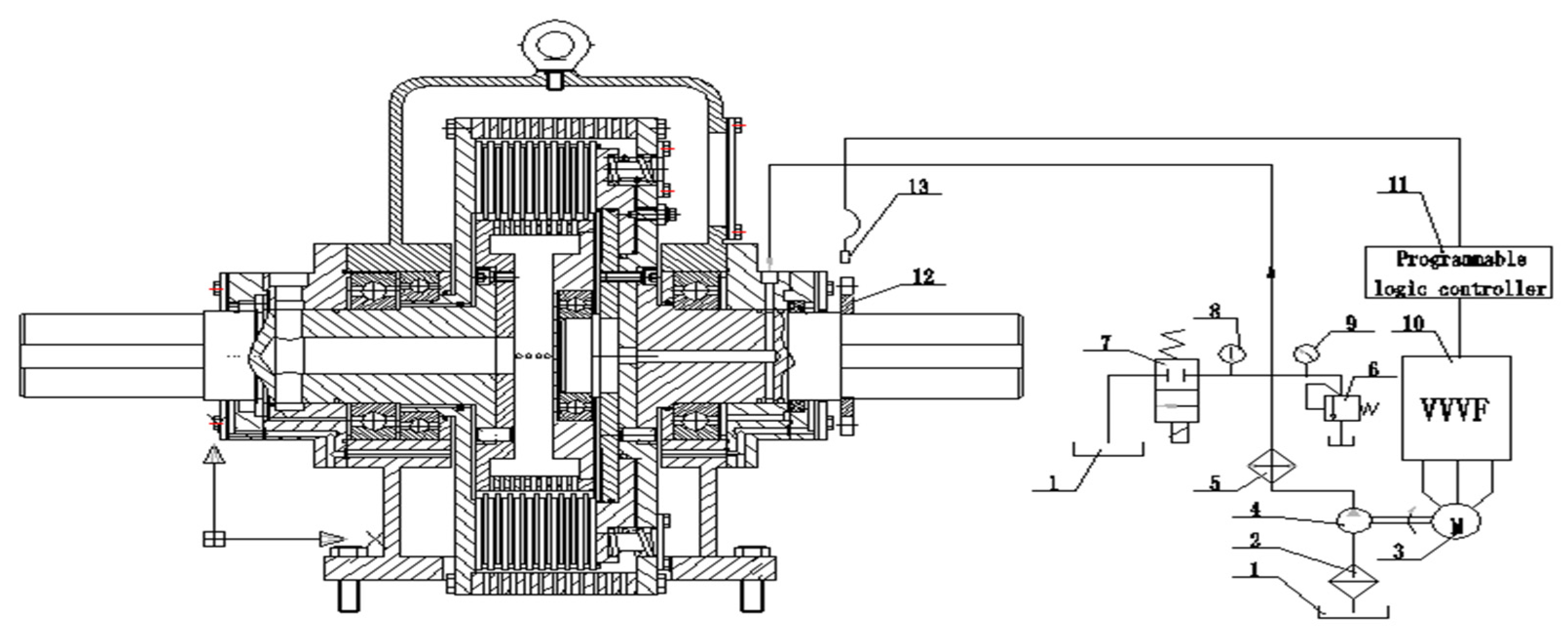
2. Overall and Detailed Design for HVC’s Control System

Table 1 shows the applied technical parameters of HVC.
During the engineering application of HVC with a proportional relief valve, we could see the phenomenon that the output rotational speed of HVC will fluctuate wildly every 10 min [19]. As is known to all, frictional disks will wear down after running for a certain time, which will cause particles. Additionally, oil temperature will rise because of slip loss when the HVC is working at the slip condition. Then, sludge deposition will be produced in lubricant oil under a high temperature situation. Thus, impurities such as particles and depositions will result in the clogging problem for valves. Because the HVC was designed as a normal closed structure as is shown in Figure 1, that is to say, the frictional disks of HVC are clamped by preload spring in the initial state, system pressure of HVC will fluctuate according to the different positions of the relief valve’s spool [20].
In some cases, reliability is considered to be more important to dynamic performance. Therefore, the pump control system is usually used to replace the valve control system [21,22,23,24]. Compared to the proportional relieve valve, the gear pump requires less cleanliness of the oil. Therefore, the new pump system composed of a frequency converter-electric motor-gear pump is steadier than the valve control system. Its diagrammatic sketch is as follows.
Figure 1 shows the signal transform process: Firstly, water pressure “P” can be transformed by a water pressure converter into electric current signal “I”, which will be sent to PLC. Secondly, after dealing with the current signal, the current signal “I” will be sent by PLC to the frequency converter. Thirdly, based on the current signal, the frequency converter produces a specific frequency voltage signal to the electric motor. Fourthly, the gear pump will be powered by the electric motor at a certain speed and supply a required oil pressure for HVC. Finally, HVC outputs a certain speed for the water pump, which can be changed to adjust the water supply, so as to realize the regulation of the pipe pressure of waterworks.
Different from changing the output speed of electric motor by variable frequency speed control technology, the HVD technology is used to change the output speed of HVC, while the output speed of electric motor remains the same. When the water pressure of pipe network need to be increased, we can increase the output seed of HVC by reducing the distance between two friction disks, then the water pump will output more water flow, finally, the water pressure will rise, and vice versa. If we want the pressure of the pipe network to be kept constant during a period, then we should make the output speed of HVC stable and follow the change of the disturbance. Its schematic diagram (shown in Figure 2) is as follows.
As shown in Figure 3, HVC is mainly composed of an input axis, a lubricating oil chamber, friction plates, separator plates, a hydraulic cylinder, an output axis and other parts.
The proposed pump control system of HVC is mainly composed of an electric motor, s frequency converter, a gear pump, a PLC, etc.
A branch of hydraulic oil passes through the filter, gear pump and safety valve and then returns to the oil tank. Safety valve 6 is used to set a limited oil pressure for the system. Another branch of the hydraulic oil passes from the electromagnetic valve to the tank, which can sharply drop the control oil pressure to 0 in emergency circumstances.
The third branch of oil goes directly into the cylinder of HVC. According to the different frequency produced by frequency converter, the gear pump can provide control oil with different pressure for HVC.
The speed sensor can read and feedback the speed signal to PLC. Through its analog modules, the speed signal can be converted into a current signal by PLC. Finally, different oil flow and pressure can be achieved by VVVF control.

3. Modeling and Simulation of the Pump Control System of HVC

As we know, it is difficult for the conventional PID control to achieve high control precision, because the constant pressure water supply system is characterized by nonlinearity, time varying and large inertia. Additionally, when the HVC is working at different output speed, its mathematic model is always changing. Therefore, it is difficult to precisely identify the HVC by the fixed PID parameters. As is known to all, Fuzzy-PID control can deal with such problems well because the PID parameters can be regulated according to the change of system model. Therefore, we designed a Fuzzy-PID controller according to the new pump control system of HVC. Its structural diagram is represented in Figure 4 and its theoretical model of each part can be established as below.

3.1. Frequency Converter

According to the electric motor of gear pump, we chose the F1000-G0007S2B type frequency converter, which can output a certain electrical signal. Its mathematical model is as follows
U 1 = K f K i n t I r
where Kf is the conversion coefficient of frequency-voltage. Kint is the conversion coefficient of Frequency-current. Ir is the input current, and U1 is the output voltage.

3.2. Gear Pump and the Cylinder of HVC

The gear pump is a linear component as its output flow can be controlled almost linearly to its output rotational speed. We chose the gear pump (CB-B10) as the hydraulic power source according to the required control oil pressure for HVC, its mathematical model can be obtained by ignoring the leakage:
Q = n V η v / 60 = K q n n
K q n n V e β e P = A ( P A K 1 )
G ( s ) = Δ p Δ n = K 1 K q n ( K 1 V e β e + A 2 ) s
where K1 is the stiffness coefficient of spring (which can be seen as the load for the cylinder of HVC), Q is the flow of the cylinder, A is the area of the piston, βe is the bulk modulus of hydraulic oil, Ve is the equivalent volume of the cylinder, p is the pressure of the cylinder, and n is the output speed of the gear pump. V is the displacement of gear pump, and ηv is the volumetric efficiency of gear pump.

3.3. Gear Pump Motor

An asynchronous motor (YVP90S-4) was applied according to the power required by the gear pump. It is hard to obtain an accurate mathematical model of asynchronous motor as it is a high-order nonlinear system. By ignoring transient process of electromagnetic field, its electromagnetic torque equation can be obtained
T n = 3 m p U 1 2 ( R 2 / s ) ω 1 [ ( R 1 + R 2 s ) 2 + ω 1 2 ( L 1 + L 2 ) 2 ] = 3 m p ( U 1 ω 1 ) 2 s ω 1 R 2 ( s R 1 + R 2 ) 2 + s 2 ω 1 2 ( L 1 + L 2 ) 2
where mp is the magnetic pole number of the AC asynchronous motor, R1 is the stator phase resistance of the asynchronous motor, R2 is the rotor phase resistance equivalent to the stator side of the asynchronous motor, U1 is the phase voltage of the stator, ω1 is the rotational speed of the motor, s is the slip ratio of the asynchronous motor, L1 is the stator leakage inductance of the asynchronous motor, L2 is the rotor leakage inductance equivalent to the stator side of the asynchronous motor, and Tn is the electromagnetic torque of the asynchronous motor.
When the asynchronous motor is working at the rated condition,
s = 0.09 , R 2 s R 1 , R 2 s ω 1 ( L 1 + L 2 )
Therefore, Equation (5) can be simplified as
T n 3 m p U 1 2 R 2 / s 2 π f ( R 2 / s ) 2 = 3 m p U 1 2 2 π f R 2 s
Because
s = 1 ( n n s ) , n s = 60 f m p ,
Therefore,
T n = 3 m p 2 π R 2 K f U 1 m p 2 40 π R 2 K f 2 n p = K a U 1 K b n
K f = U 1 f       K a = 3 m p 2 π R 2 K f K b = m p 2 40 π R 2 K f 2
Through ignoring energy loss, we can obtain
P Q = T n ω 1
From Equations (2), (4), (7) and (8), we can finally obtain the transfer function of the asynchronous motor as follows
G ( s ) = Δ n Δ f = π 30 K a K f s π 30 K b s + K p n K 2 q n
where
K p n = β e K 1 β e A 2 + V e K 1

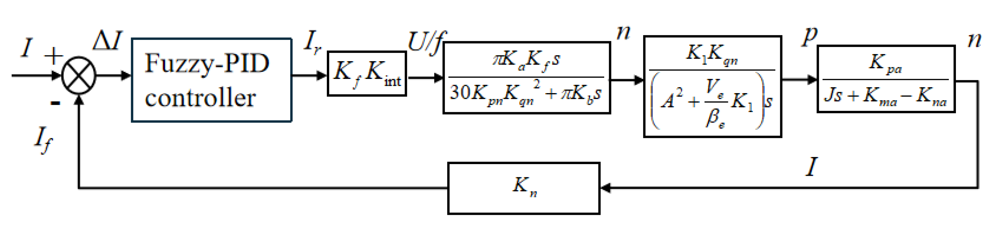
3.4. Modeling of HVC

HVC is the key part of the constant pressure water supply system, through which we can finally control the water pressure and flow. HVC transmits torque and power by oil film between its frictional disks. According to the Newton’s inner friction law, oil film shear stress τ is related to input rotational speed of HVC n1, output rotational speed of HVC n2, oil dynamic viscosity μ and oil pressure of cylinder p, and the function can be described as
τ = F 1 ( μ , n 1 , n 2 , p )
Therefore, the output torque transmitted by HVC can be obtained as
T l = n r 1 r 2 2 π τ r 2 d r = n r 1 r 2 2 F 1 ( μ , n 1 , n 2 , p ) π r 2 d r
where n is the number of frictional disks, r2 is the outside radius, and r1 is the inside radius.
When HVC is working at the stable state, n1, μ can be regarded as constant, thus
T l = F 2 ( p , n 2 )
By increment linearization at the work point a ( p a , n 2 a , T a ) , so
Δ T l = F 2 p Δ p + F 2 n 2 Δ n 2
Assume
K p a = F 2 p | p = p a , n 2 = n 2 a K n a = F 2 n 2 | p = p a , n 2 = n 2 a
Thus
Δ T l = K p a Δ p 1 + K n a Δ n 2
where Kpa is the torque-pressure gain in, and Kna is the torque-speed gain.
According to the Newton’s second law,
Δ T l = J d Δ n 2 d t + K m a Δ n 2
where
K m a = F 3 n 2 | n 2 = n 2 a
Kma is the load factor, and J is the load moment of inertia.
After Laplace transformation, Equation (13) becomes
Δ n 2 = 1 J s + K m a Δ T l
From Equations (14) and (16), we can finally obtain the transfer function of HVC as
G ( s ) = Δ n 2 Δ p = K p a J s + K m a K n a

3.5. Programmable Logic Controller

As we known, when working under the mixed friction condition, surfaces of the HVC’S frictional plates begin to contact together. Because of the complex and variable surface topography, the mixed friction sate is unstable. Therefore, closed-loop feedback control is indispensable for reducing the output speed fluctuation of HVC. We chose PLC as the control center, and it can be seen as a proportional coefficient of Kn. Finally, we can obtain the transfer function block diagram of the new system shown in Figure 5.
According to the actual parameters, we can obtain the simplified transfer function of the new pump control system of HVC as follows
G ( s ) = Δ n 2 Δ i = 20 1.6 s 2 + 4.4 s + 1

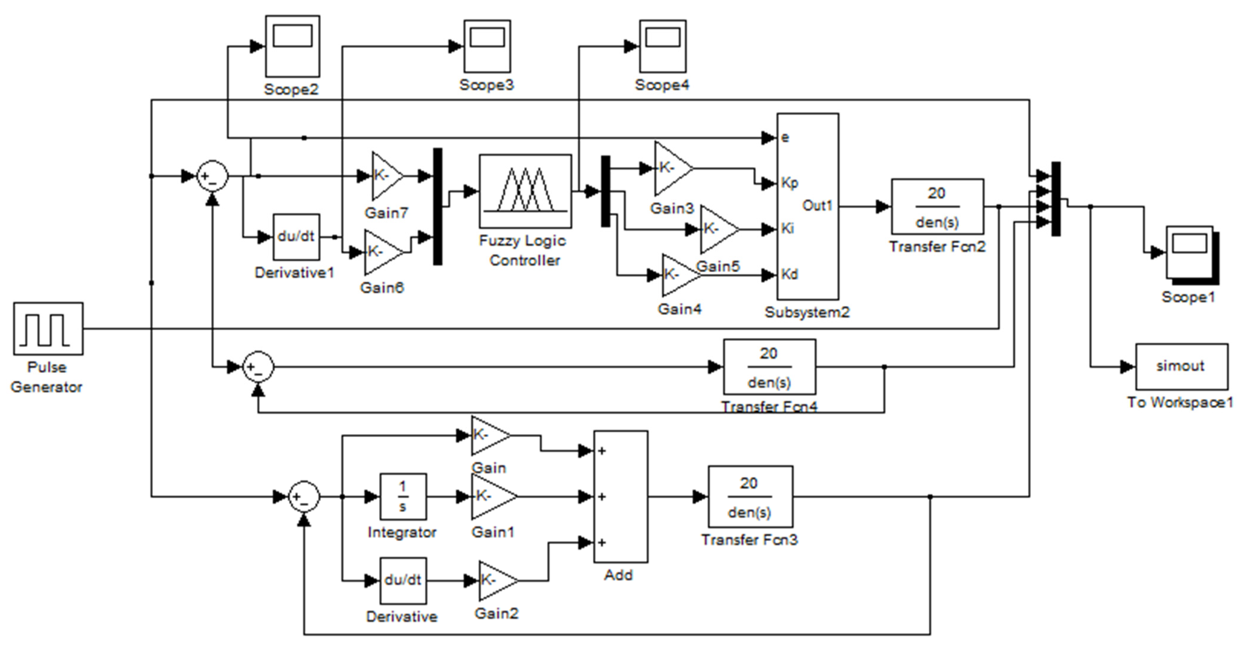
3.6. Simulation of the New System

Based on the theoretical model, analysis of the conventional PID control and Fuzzy- PID control is carried out through MATLAB simulation. In accord with the parameters of the conventional PID control, the the Fuzzy-PID control’s initial values are (Kp = 1.7, Ki = 0.15, and Kd = 0.2) based on the rule of “Ziegler–Nichols”, and the quantitative factor and proportional factor are, respectively, Ke = 1, Kec = 0.55, ΔKp = 0.6, ΔKi = 0.8, and ΔKd = −0.2. The input (e, ec) and output variables (ΔKp, ΔKi, ΔKd) are described by seven fuzzy subsets {NB, NM, NS, ZO, PS, PM, PB}. Table 2 is established based on the common fuzzy control regulation which is generally used in the controlling of HVC [25,26,27,28]. Each row of Table 2. from left to right is respectively the fuzzy control regulation of Kp, Ki, and Kd. The structural diagram of the Fuzzy-PID controller is shown in Figure 6, and the membership function and surface viewer of the Fuzzy-PID controller is shown in Figure 7. Selecting some simple membership functions that reflect the results of fuzzy inference can significantly simplify the calculation process of fuzzy inference. The shape of the membership function of fuzzy quantity is bell-shaped in theory, but it is often simplified to a triangle in the actual control process. As shown in Figure 7, the input (e, ec) and output variables (ΔKp, ΔKi, ΔKd) obey the triangular membership function. The centroid method has been applied for defuzzification, as it is the most commonly used method.
Three different simulation works were carried out using MATLAB. Through using a square wave as an input signal, three different output curves were indicated in Figure 8, we can see that the Fuzzy-PID control method has the best tracking ability, the smallest overshoot and the shortest adjustment time.
Increased an added interference signal by 0.5 after 5 s in each period, the simulation curves are showed in Figure 9. It can be seen that the conventional PID control has nearly no anti-interference ability, while the Fuzzy-PID control is characterized by small fluctuations and a strong anti-interference ability.

4. Experiment Results

As shown in Figure 4, the following is the realization process of Fuzzy-PID control in the experiment.
(1)
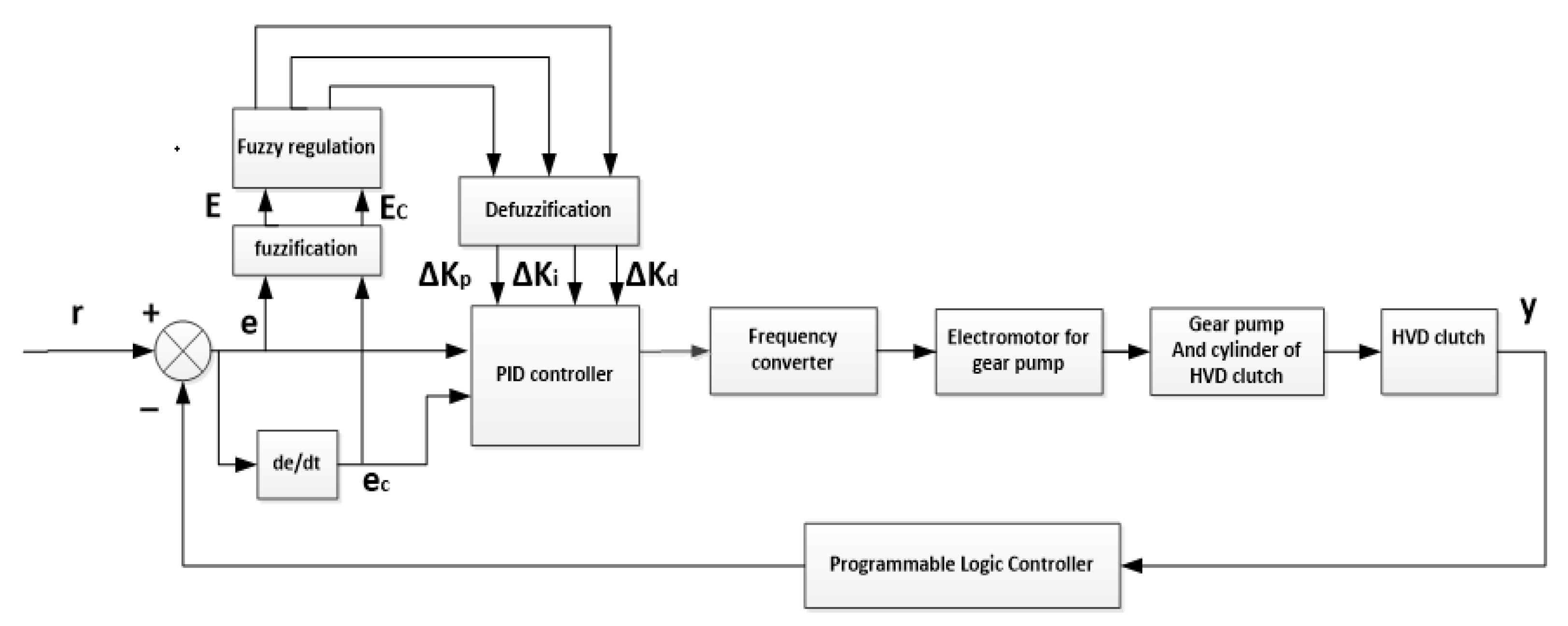
Calculate the error “e” between the actual value of pipe pressure of waterworks and the feedback value. The real-time pipe pressure value can be obtained through the pressure transmitter, and then the error of pipe pressure can be obtained by comparing with the target pressure value of the waterworks.
(2)
Calculate the error change rate “de/dt”. The error is differentiated to calculate the change of error in an A/D sampling period.
(3)
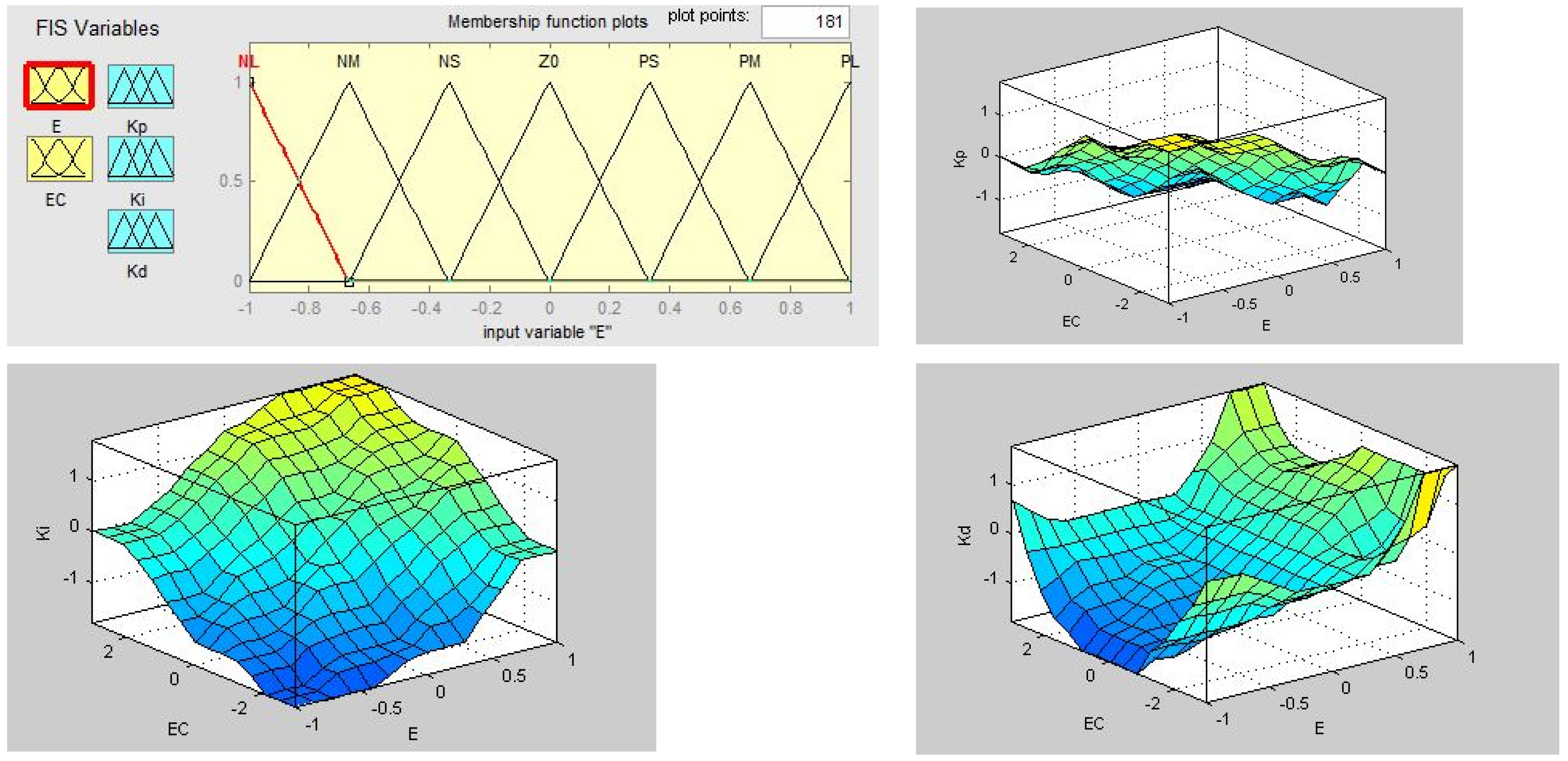
Fuzzification of input. The obtained accurate error “e” and error change rate “ec” are fuzzed into fuzzy quantities.
(4)
Establish control rules. Establish the strategies required in the control with the knowledge of experts or the experience of field operators, as shown in Table 2.
(5)
Fuzzy inference. The fuzzy inference input variables E and EC are used as the inputs of the fuzzy inference part, and then the fuzzy inference is carried out by E, EC and the control rule R according to the inference synthesis rule to obtain the fuzzy control quantity U.
(6)
Defuzzification. In order to apply accurate control to the controlled object, the fuzzy control quantity must be transformed into an accurate quantity, that is, defuzzification.
(7)
Real time regulation of PID control parameters. After the fuzzy control quantity is transformed into an accurate quantity, the three control parameters Kp, Ki and Kd of PID are modified in real-time to make the control system reach the optimal control state.
(8)
Regulation of frequency converter output frequency. The three control parameters of PID are modified in real time to adjust the output frequency of frequency converter and make the oil pump motor of control oil circuit work at an appropriate frequency, so as to realize the regulation of the output speed of HVC.
(9)
Regulation of the pipe pressure of waterworks. By changing the working frequency of the oil pump motor in the control oil circuit, the output speed of the hydro-viscous clutch (i.e., the speed of the water pump) is changed to adjust the water supply, so as to realize the regulation of the pipe pressure of waterworks.
The HVC with the special pump control system has been successfully applied in the 4th waterworks of Shaoyang (Hunan province). The field and experimental data are shown below (Figure 10 and Figure 11).
From Figure 12 we can see, with the proportional relieve valve, when the transmission ratio is set to 0.84, the output speed of HVC increases from 630 to 660 r/min after 16 min then drops to 604 r/min after 28 min. When the transmission ratio is set to 0.92, the output speed of HVC increases from 690 to 723 r/min after 10 min then drops to 661 r/min after 22 min, and then rises to 716 r/min after 32 min. Correspondingly, as it shows in Figure 13 and Figure 14, when the transmission ratio is 0.84, the pipe pressure of waterworks rises from 0.3 to 0.41 MPa after 16 min then drops to 0.18 MPa after 28 min. When the transmission ratio is 0.92, the pipe pressure of the waterworks rises from 0.32 to 0.44 MPa after 10 min then drops to 0.195 MPa after 22 min, and then rise to 0.43 MPa after 32 min.
From Figure 12, Figure 13 and Figure 14 we can also see, after the improvement of PID control, the output speed fluctuation of the new pump control system is nearly decreased from ±60π to ±10π rad/min. Moreover, based on the Fuzzy-PID controller, the output speed fluctuation is decreased to ±6π rad/min and the pressure fluctuation of distribution network is decreased to ±0.002 MPa, which verified the previous theoretical analysis and fulfilled the requirements of water works well.
As it shows in Table 3, when reducing the transmission ratio of HVC from 1 to 0.82, the current consumed by DC motor decreased significantly from 2 to 11.9 A, and the smaller transmission ratio of HVC is, the more obvious the energy-saving effect is.

5. Conclusions

Traditional HVC generally uses valve control system to control the output speed of clutch. Due to the dead zone, oil pollution and other reasons, there is a problem of large water pressure fluctuation in the HVC’s application of a constant pressure water supply system. Because the control accuracy of pump control system is lower than that of a traditional valve control system, in order to meet the high-precision requirements of users and further expand its application field, the Fuzzy-PID control method is proposed. From all the above analysis, the following conclusions can be drawn.
(1)
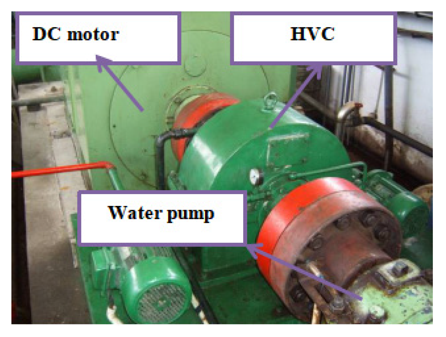
A new pump control system which is composed of a frequency converter, an-electric motor and a gear pump was used to replace the proportional relief valve for HVC, which can solve the blockage and dead-zone problem of the valve control system.
(2)
A mathematical model of the pump control system was established, transfer function of which can be simplified to a second order system.
(3)
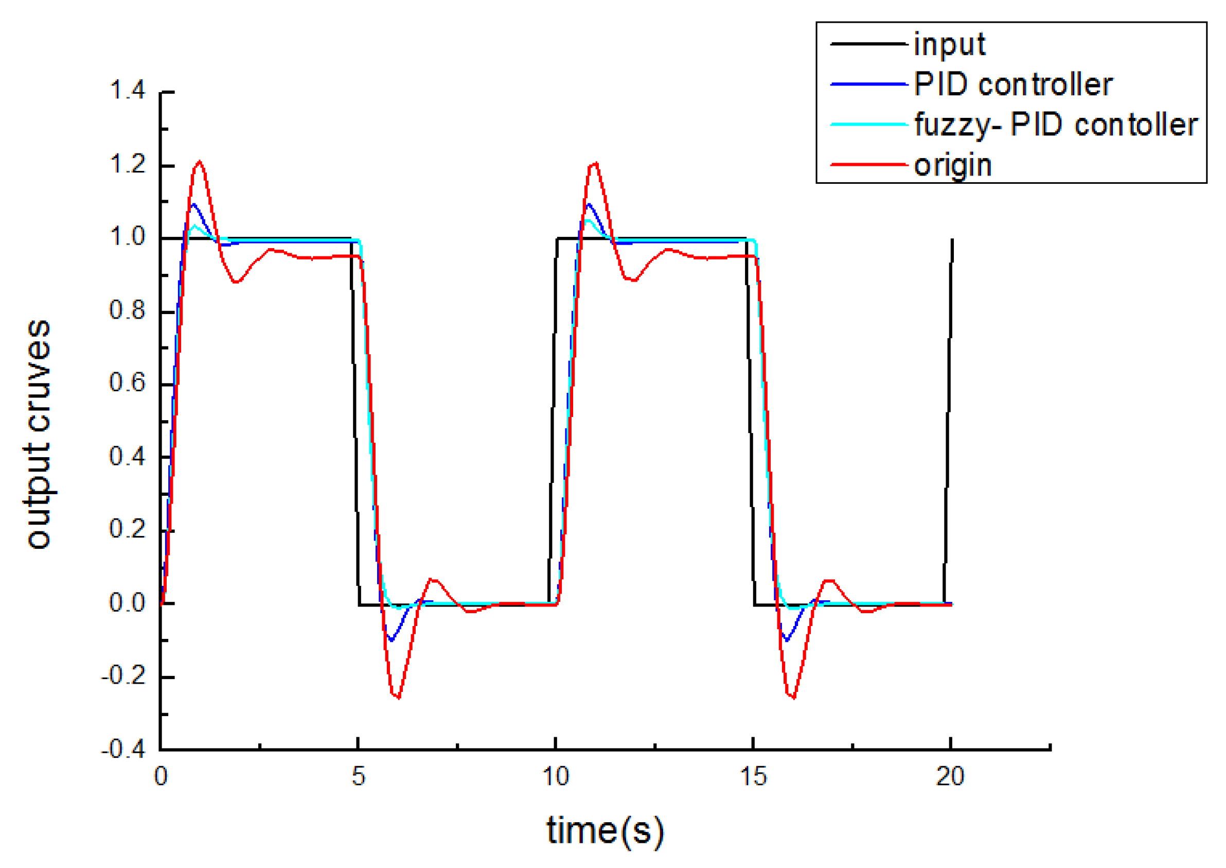
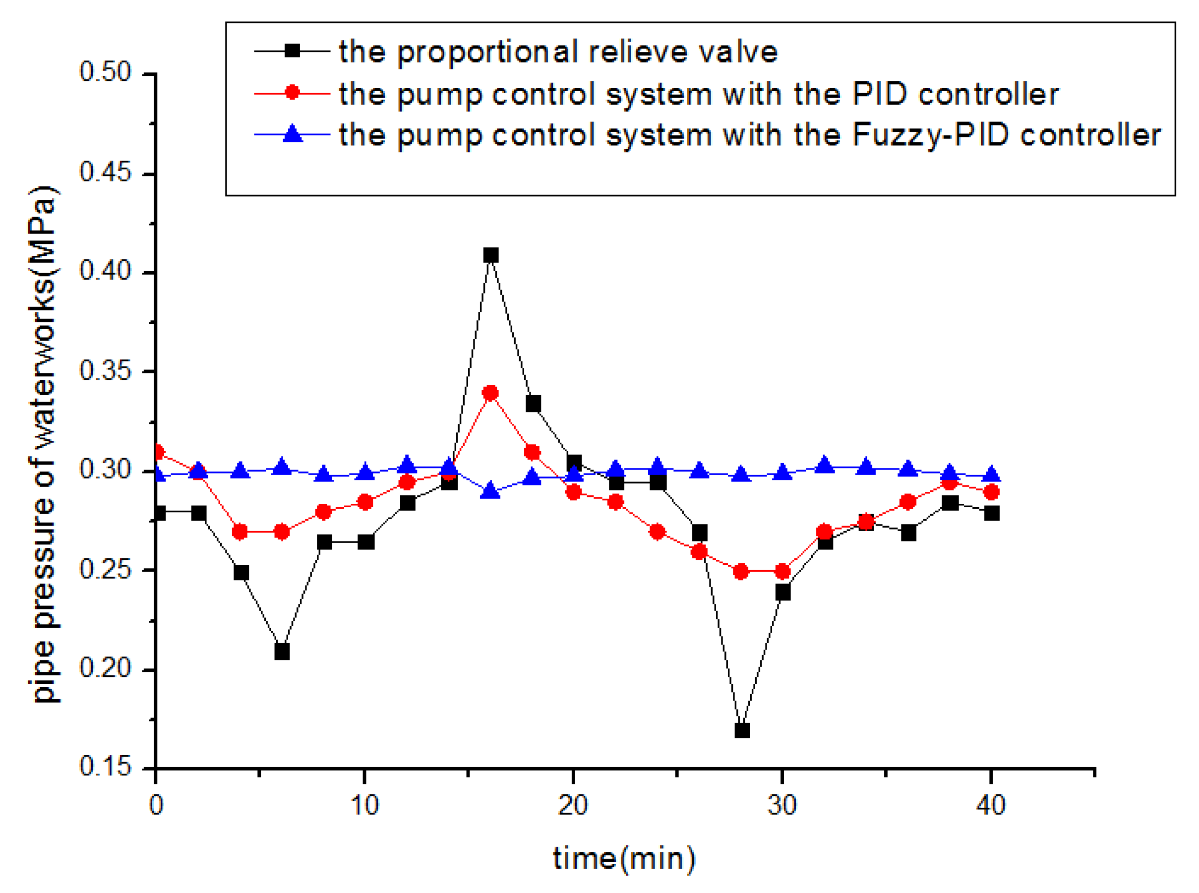
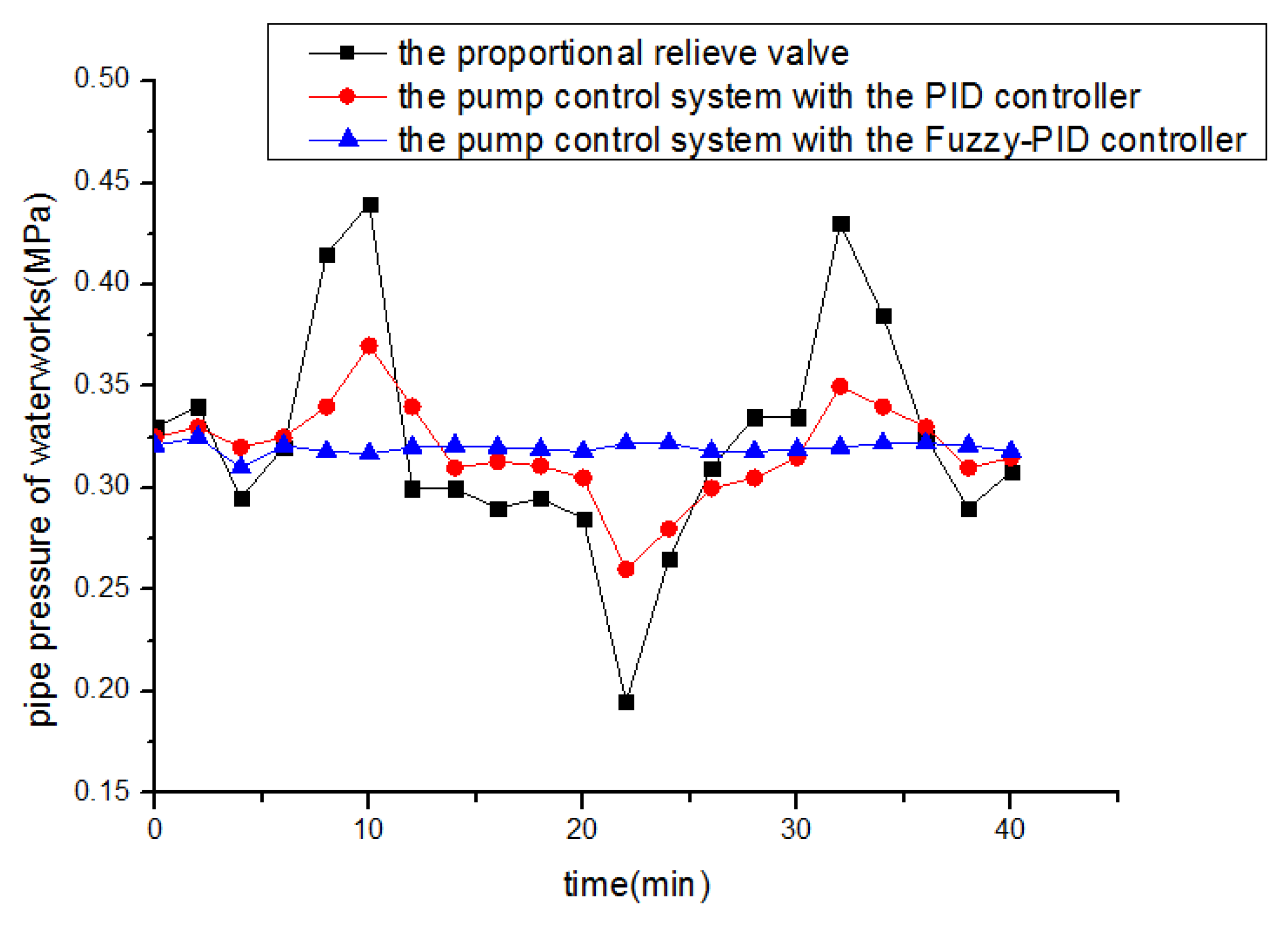
In order to improve the performance of the new pump control system, a Fuzzy-PID controller was designed. The simulation results show that: compared with the conventional PID control, the Fuzzy-PID control method has a better tracking ability, a smaller overshoot, a shorter adjustment time and a stronger anti-interference ability. Therefore, the Fuzzy-PID control method is more suitable for HVC.
(4)
To verify our theoretical analysis results, a relative industrial experiment was carried out and the tested data show that, by applying the pump control system of HVC based on the Fuzzy-PID controller, the speed fluctuation range of HVC is reduced to ±6π rad/min, the pressure fluctuation of distribution network is reduced to ±0.002 MPa, and the current consumed by DC motor decreased significantly from 28 to 11.9 A.

Author Contributions

Writing—original draft preparation, X.L.; writing—review and editing, S.Y.; supervision, D.H.; project administration, G.G. and X.P. All authors have read and agreed to the published version of the manuscript.

Funding

This work was supported by the grant from the Natural Science Foundation of Hunan Province of China (2017JJ3057, 2021JJ30378), the Research Foundation of Education Bureau of Hunan Province of China (20B325), the Open Research Fund of State Key Laboratory of High Performance Complex Manufacturing, Central South University (Kfkt2019-13), the Natural Science Foundation of Guangdong Province, (2021A1515010818), and the Department of education of Guangdong Province of China (2019KTSCX039).

Conflicts of Interest

The authors declare that there is no conflict of interests regarding the publication of this paper.

References

  1. Meng, Q.R.; Hou, Y. Mechanism of hydro-viscous soft start of belt conveyor. J. China Univ. Min. Technol. 2008, 18, 459–465. [Google Scholar] [CrossRef]
  2. Hou, Y.F.; Xie, F.W. Control strategy of disc braking system for downward belt conveyor. Min. Sci. Technol. 2011, 21, 491–494. [Google Scholar] [CrossRef]
  3. Li, F.S. The Analysis of Several Typical Speed Control Systems for HVD. Shandong Inst. Electr. Power 2003, 1, 42–45. (In Chinese) [Google Scholar]
  4. Wei, C.G.; Zhao, J.X. Hydro-Viscous Transmission Technology; National Defence Industry Press: Beijing, China, 1996; pp. 47–50. [Google Scholar]
  5. Mikael, H. Optimizing the smoothness and temperatures of a wet clutch engagement through control of the normal force and drive torque ASME. J. Tribol. 2000, 122, 119–123. [Google Scholar]
  6. Huang, X.G.; Wei, C.G. Stability of oil Film and Out Put Speed of Hydroviscous Drive Affected by the Pressure of Control Oil. J. Beijing Inst. Technol. 2001, 10, 266–271. [Google Scholar]
  7. Wei, J.H.; Chen, N. Research on the soft start-up performance of hydro-viscous drive. J. Coal Sci. Eng. 2004, 10, 70–72. [Google Scholar]
  8. Ferreira, F.J.; Fong, J.A.; de Almeida, A.T. Eco-analysis of Variable Speed Drives for Flow Regulation in Pumping Systems. IEEE Trans. Ind. Electron. 2011, 58, 2117–2125. [Google Scholar] [CrossRef]
  9. Lamaddalena, N.; Khila, S. Energy saving with variable speed pumps in on-demand irrigation system. Irrig. Sci. 2012, 30, 157–166. [Google Scholar] [CrossRef]
  10. Mao, H.C.; Chung, C.C.; Chung, F.J. The high response and high efficiency velocity control of a hydraulic injection molding machine using a variable rotational speed electro-hydraulic pump-controlled system. Int. J. Adv. Manuf. Technol. 2009, 43, 841–851. [Google Scholar]
  11. Ding, H.G.; Zhao, J.Y. A New Method of Improving Low-Speed Performance of Variable Speed Hydraulic Systems: By Leaking Parallel Valve Control. Adv. Mech. Eng. 2014, 6, 1–10. [Google Scholar] [CrossRef]
  12. Zhao, J.Y.; Ding, H.G.; Han, G.Z.; Yang, H.F. A New method of Improving Comprehensive Performances of Variable Speed Pump Control Systems with Large power: Valve pump Parallel Variable Structure Control. In Proceedings of the 2015 International Conference on Fluid Power and Mechatronics, Harbin, China, 5–7 August 2015; pp. 187–193. [Google Scholar]
  13. Gong, G.; Wang, F.; Qin, Y.; Zhang, Y.; Sun, C.; Yang, H. The design of low cost valve-and-pump compounded pressure control system for the hydro viscous clutch. Mechatronics 2020, 65, 102310. [Google Scholar] [CrossRef]
  14. Qin, Y.; Gong, G.; Wang, F.; Sun, C. Research on pressure control strategy of hydraulic system of hydro-viscous variable speed clutch. J. Harbin Eng. Univ. 2020, 41, 1377–1383. [Google Scholar]
  15. Qin, Y.F.; Gong, G.G.; Wang, F.; Sun, C.C. Displacement controller design for piston of hydro-viscous clutch based on RBF neural network. Chin. J. Eng. Des. 2019, 26, 603–610. [Google Scholar]
  16. Qi, H.; Liu, S.; Yang, R.; Yu, Y. Research on new intelligent pump control based on sliding mode variable structure control. In Proceedings of the 2017 IEEE International Conference on Mechatronics and Automation (ICMA), Takamatsu, Japan, 6–9 August 2017; pp. 1239–1244. [Google Scholar]
  17. Jahmeerbacus, M.I. Flow Rate Regulation of a Variable Speed Driven Pumping System Using Fuzzy Logic. In Proceedings of the 4th International Conference on Electric Power and Energy Conversion Systems, Tokyo, Japan, 24–26 November 2015; pp. 1–6. [Google Scholar]
  18. Kastrevc, M.; Pusenjak, R. Fuzzy Pressure Control of Hydraulic System with Gear Pump Driven by Variable Speed Induction Electro-motor. Exp. Tech. 2005, 29, 57–62. [Google Scholar] [CrossRef]
  19. He, S.J.; Zhu, S.S.; Bai, Q. Fault’s analysis and improvement of hydro-viscous speed-regulation clutch used in constant pressure water supply. In Proceedings of the Fifth Session of the National Fluid Power Transmission and Control Conference and the 2008 Air Institute of Hydranlic and Pneumatic Conference of China, Beijing, China, 1 October 2008; pp. 66–70. [Google Scholar]
  20. Liao, X.P.; Gong, G.F.; Zhou, T.Y.; Wang, H. New design of the control system for hydro-viscous clutch. In Proceedings of the IEEE International Conference on Advances in Engineering and Technology Research, Unnao, India, 1–2 August 2015; pp. 1–4. [Google Scholar]
  21. Mao, H.C. A novel pitch control system for a wind turbine driven by a variable-speed pump-controlled hydraulic servo system. Mechatronics 2011, 21, 753–761. [Google Scholar]
  22. Ciotu, M.; Popescu, D.; Motocu, M. Analysis of Energy Efficiency by Replacing the Throttle Valve with Variable Speed Drive Condensate Pump from E.C. Turceni. In Proceedings of the 3rd International Symposium on Electrical and Electronics Engineering (ISEEE ‘10), Galați, Romania, 16–18 September 2010; IEEE: New York, NY, USA, 2010; pp. 293–297. [Google Scholar]
  23. Shen, H.K.; Jin, B.; Chen, Y. Study on energy-saving variable speed hydraulic control system. In Proceedings of the International Conference on Advanced Design and Manufacture, Harbin, China, 8–10 January 2006; pp. 806–811. [Google Scholar]
  24. Yuan, K.; Zhang, Y. The Application of VVVF in the Hydro viscous Dynamometer and Simulation Based on MATLAB. In Proceedings of the 3rd International Conference on Power Electronics and Intelligent Transportation System, Shenzhen, China, 13–14 November 2010; pp. 321–324. [Google Scholar]
  25. Malki, H.A.; Li, H.; Chen, G. New design and stability analysis of fuzzy proportional-derivative control systems. IEEE Trans. Fuzzy Syst. 1994, 2, 245–254. [Google Scholar] [CrossRef]
  26. Xie, F.W.; Hou, Y.F.; Xu, Z.P.; Zhao, R. Fuzzy-immune control strategy of a hydro-viscous soft start device of a belt conveyor. Min. Sci. Technol. 2009, 19, 544–548. [Google Scholar] [CrossRef]
  27. Meng, Q.R.; Hou, Y.F. Research of optimal fuzzy control of hydro-viscous drive soft starter of belt conveyor. China Min. Mag. 2007, 16, 63–65. [Google Scholar]
  28. Sun, C.C.; Gong, G.F.; Wang, F. Fuzzy control strategy for hydro-viscous clutch. In Proceedings of the 9th Fluid Power Transmission Control Conference of China (9th FPTC-2016), Hangzhou, China, 17–18 November 2016; pp. 883–887. [Google Scholar]
Figure 1. Diagrammatic sketch of HVD control system.
Energies 14 08282 g001
Figure 2. Schematic diagram for the HVD control system. 1. electric motor; 2, 4, 6. flexible coupling; 3. HVC; 5. speed sensor; 7. water pump.
Energies 14 08282 g002
Figure 3. New hydraulic pump control system for HVC. 1. Hydraulic oil tank; 2. filter; 3. gear pump motor; 4. gear pump; 5. chiller; 6. safety valve; 7. electromagnetic valve; 8. thermometer; 9. manometer; 10. frequency converter; 11. PLC; 12. measuring speed gear; 13. speed sensor.
Energies 14 08282 g003
Figure 4. System block diagram based on the Fuzzy-PID controller.
Energies 14 08282 g004
Figure 5. Transfer function block diagram of the new system for HVC.
Energies 14 08282 g005
Figure 6. Structural diagram of Fuzzy-PID controller.
Energies 14 08282 g006
Figure 7. The membership function and surface viewer of the Fuzzy-PID controller.
Energies 14 08282 g007
Figure 8. Response curves of different control methods.
Energies 14 08282 g008
Figure 9. Response curves of different control methods.
Energies 14 08282 g009
Figure 10. Test field of HVC.
Energies 14 08282 g010
Figure 11. Electric control cabinet.
Energies 14 08282 g011
Figure 12. Output speed fluctuation of HVC.
Energies 14 08282 g012
Figure 13. Pipe pressure fluctuation when transmission ratio = 0.84.
Energies 14 08282 g013
Figure 14. Pipe pressure fluctuation when transmission ratio = 0.92.
Energies 14 08282 g014
Table 1. Original technical parameters of water supply system.
ParameterValueUnit
Rated power of HVD471KW
Rated torque of HVD6000N·m
Oil pressure0.2–2MPa
Rated power of DC motor355KW
Rated voltage of DC motor1000V
Flow of water pump2700m3/h
Lift of water pump39m
pressure of Pipe network0.29–0.34MPa
Table 2. Regulation table of fuzzy control.
ECNBNMNSZOPSPMPB
E
NBPBNBPSPBNBNSPMNMNBPMNMNBPSNSNBZOZONMZOZOPS
NMPBNBPSPBNBNSPMNMNBPSNSNMPSNSNMZOZONSNSZOZO
NSPMNBZOPMNMNSPMNSNMPSNSNMZOZONSNSPSNSNSPSZO
ZOPMNMZOPMNMNSPSNSNSZOZONSNSPSNSNMPMNSNMPMZO
PSPSNMZOPSNSZOZOZOZONSPSZONSPSZONMPMZONMPBZO
PMPSZOPBZOZONSNSPSPSNMPSPSNMPMPSNMPBPSNBPBPB
PBZOZOPBZOZOPMNMPSPMNMPMPMNMPMPSNBPBPSNBPBPB
Table 3. Energy saving effect of HVC during the test.
TimeFrequency/HzTarget Pressure/MPaRotational Speed of Water Pump/r/minCurrent of DC Motor/A
24:0–6190.29609–61011.9
6–8:30140.34743–74128
8:30–13150.33716–71424
13–17:30160.32689–69121
17:30–22170.31658–65717.8
22–24:0180.30634–63114.8
Publisher’s Note: MDPI stays neutral with regard to jurisdictional claims in published maps and institutional affiliations.

