Article

A Novel Fuzzy PI Control Method for Variable Frequency Brushless Synchronous Generators

Center for More-Electronic-Aircraft Power System, Nanjing University of Aeronautics and Astronautics, Nanjing 211006, China
*
Author to whom correspondence should be addressed.
Energies 2021, 14(23), 7950; https://doi.org/10.3390/en14237950
Submission received: 23 October 2021 / Revised: 20 November 2021 / Accepted: 23 November 2021 / Published: 27 November 2021

Abstract

:
With the application of more electric aircraft (MEA) technology, variable frequencies and high power ratings become import features of aero-generators. The brushless synchronous generator, which has a three-stage structure, is the most commonly used type of aero-generator. Due to the variation of operating conditions, the implementation of generator controllers becomes more and more difficult. In this paper, a state space model of a generator is derived and the influence of different operating conditions on the frequency response characteristics of the generator is revealed. Based on a fuzzy PI controller, an additional fuzzy logic controller is applied to modify the PI parameters of the voltage loop by introducing the generator speed to cope with the speed variation. Finally, the results of the simulations and experiments demonstrate that the dual fuzzy PI controller can improve both the steady-state and dynamic performance of the brushless synchronous generator, verifying the previous theoretical study.

1. Introduction

Due to increasingly constrained energy resources and the urgent need to reduce pollution, MEA technology [1,2] has received attention in the field of aircraft technology. The launch of the Boeing 787 [3] and the Airbus A380 [4] marked the mature application of MEA technology. MEA technology aims to replace other secondary energy sources such as mechanical, pneumatic, and hydraulic energy with as much electrical energy as possible. Thus, aero-generators are playing an important role in the system [5,6] and their capacity needs to increase. The elimination of the integrated drive generator (IDG) makes the frequency of the electrical power systems variable. Therefore, the aero-generators of MEA need to work under various operating conditions.
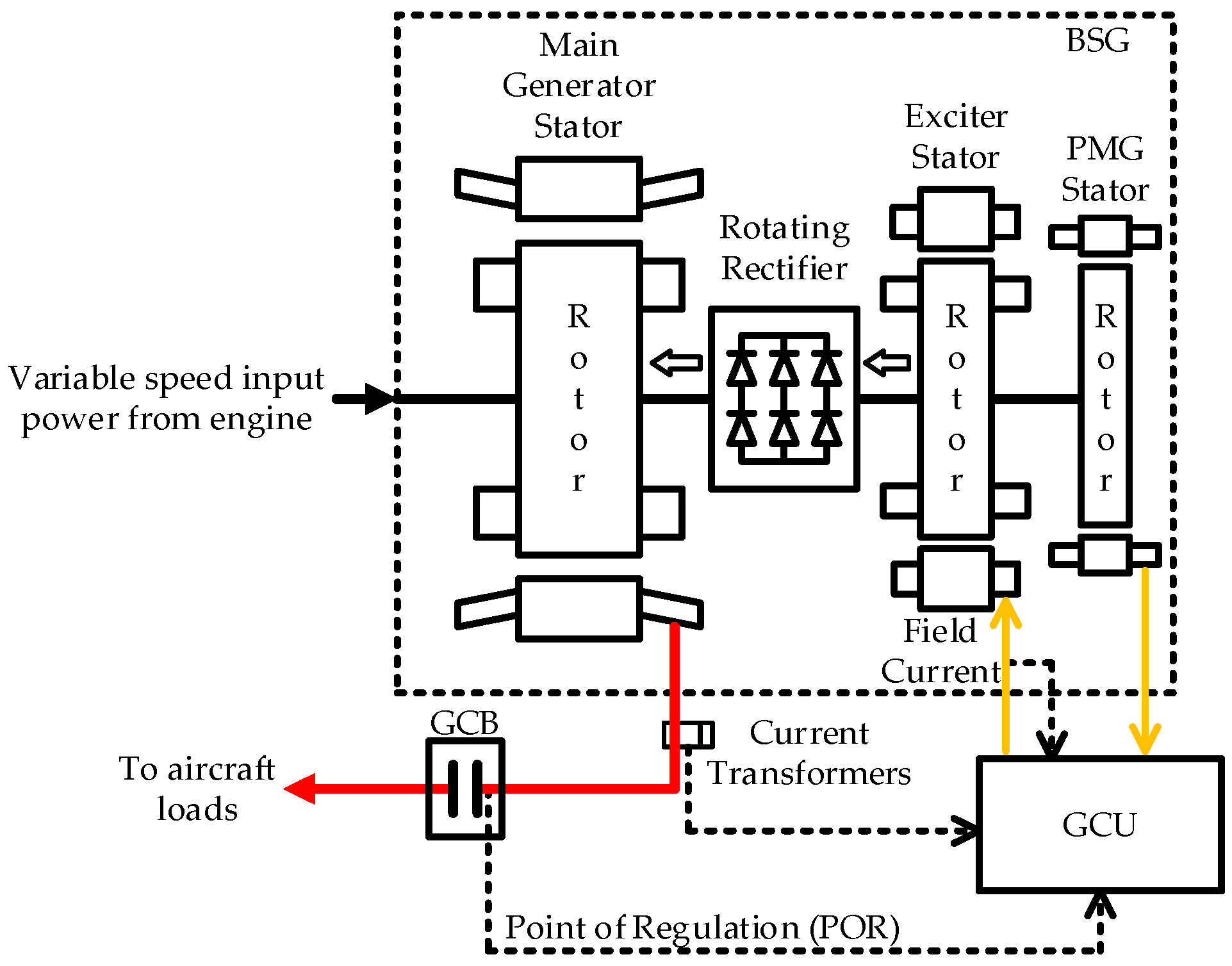
A brushless synchronous generator (BSG) consists of three stages: a main generator, an exciter, and a permanent magnet generator. A BSG is the most commonly used aero-generator because brushless excitation is achieved by the application of the exciter, which improves the service life of the synchronous generator [7,8]. As a BSG needs to control the main generator output voltage by regulating the excitation current of the exciter [9], it needs to be used in conjunction with a generator control unit (GCU). A complete power generation system structure is shown in Figure 1.
Aero-generators operate with a varying ambient temperature, speed, and load. They introduce brushless exciter and rotating rectifier links, which can have an impact on the steady-state accuracy and dynamic performance of the power generation system. Early generator controllers were implemented based on analog circuits so the control method often used a single-voltage loop control method or a dual-loop control method with an outer voltage loop and an inner field current loop. In a single-loop control, the output voltage sampling feedback is subtracted from the reference value and adjusted by the PI controller to control the power switches to regulate the output voltage. The dual-loop control method introduces an inner feedback loop of the field current based on a single-loop control [10] to improve the system performance.
The accuracy of an analog circuit is affected by the ambient temperature. In addition, the control parameter adjustment process is not convenient. Therefore, with the development of digital circuits, generator controllers have also been implemented based on digital circuits [11,12]. Due to digital controllers such as digital signal processors (DSP), it is possible to apply various new control algorithms for generator controllers [13,14,15,16,17,18]. In [17], a modified model reference adaptive system (MRAS) method for the speed sensorless control of an interior permanent magnet synchronous motor (IPMSM) was represented. In [18], a sliding mode controller was used to replace the conventional proportional-integral (PI) speed loop and a finite position phase-locked loop based on the dichotomy was added to achieve a sensorless speed control and provide an accurate rotor position angle. In [11], a three-loop control method with a load feedforward compensation link was proposed. The d-axis component of the load current was used to compensate for the reference value of the field current, which in turn improved the performance of the control system for the load variations. The method required additional load current detection circuits and a rotor position estimation method, thus increasing the complexity of the hardware and software system.
The impedance parameters of the MG and exciter vary at different operating points. In addition, the system includes a nonlinear link, the rotating rectifier, so there are many nonlinear factors in the power generator system [19,20,21]. A conventional PI controller needs a second-order linear model to describe the system [12], making it hard to tune the control parameters for aero-generators.
When the system model is highly nonlinear and the parameters always vary, a fuzzy PI controller is an effective approach. Fuzzy control has the property of a universal function approximator and the designer can model unknown processes using a series of IF-THEN fuzzy rules, which allows the future state of the system to be predicted using fuzzy models. Fuzzy control is not only used for systems that are difficult to model but also for systems where the mathematical model is known but more complex. Although the control performance cannot always be improved, the time required for the controller design and its practical application will be greatly reduced. In [22], a fuzzy PI controller was applied and the simulation results showed that the fuzzy PI controller had a better dynamic performance than a traditional voltage control method under different speed and load conditions.
This paper adopts a dual fuzzy PI controller to introduce the rotor speed into an additional fuzzy controller to compensate for the PI control parameters to achieve a better control effect in the full speed range.
Section 2 describes the system architecture of the variable frequency BSG system, establishes the mathematical model, and shows the differences in the frequency response at different operating conditions.
Section 3 presents the principle of the generator voltage regulation based on a dual fuzzy PI controller and shows its implementation method.
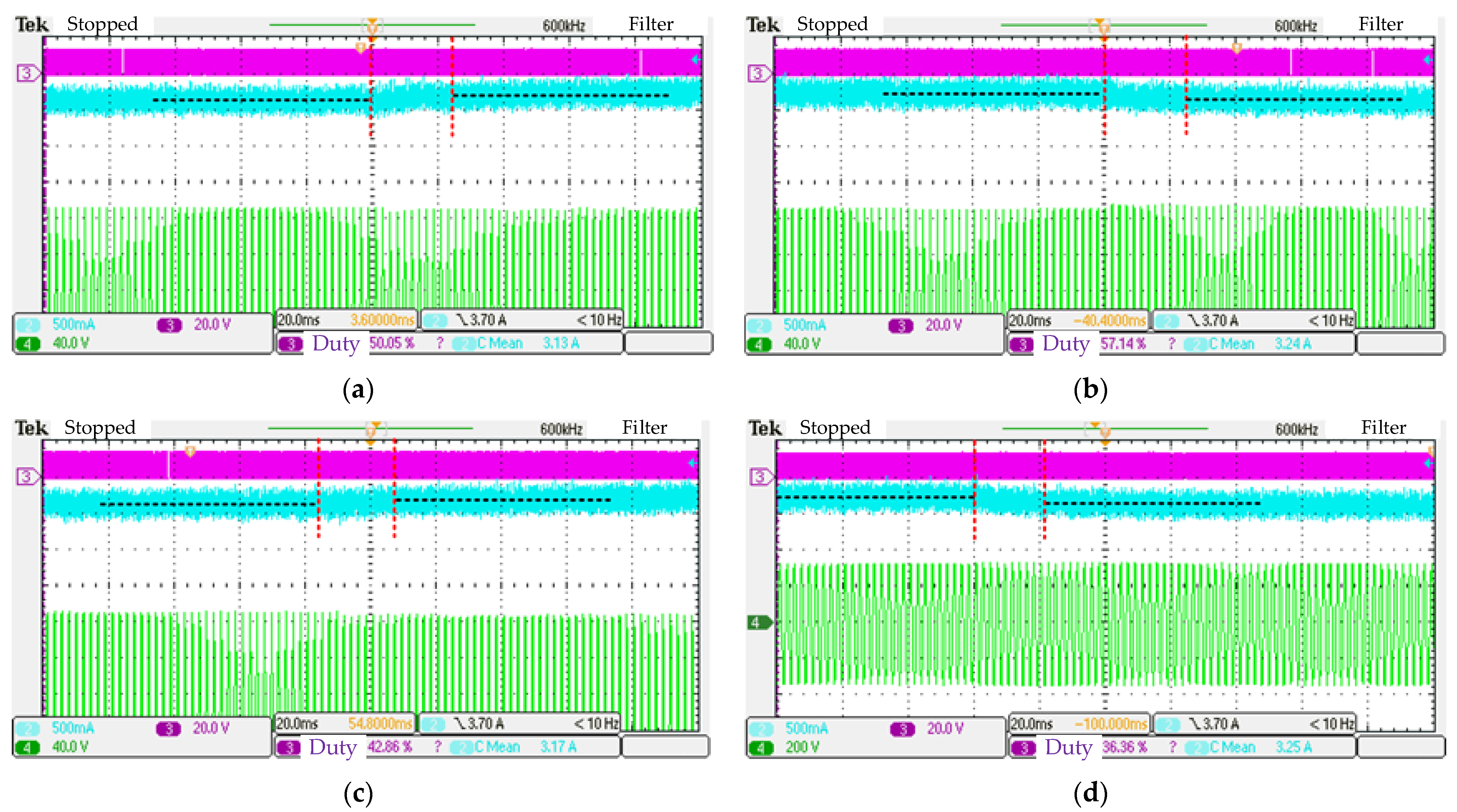
Section 4 conducts simulation tests and compares the dual fuzzy PI control strategy with a conventional PI control and a fuzzy PI control strategy without considering the rotor speed to verify the performance of the dual fuzzy PI control strategy. Additionally, an experimental platform of a variable frequency power generation system is built to verify the effectiveness of the control method proposed in this paper.

2. Generator Modeling

The power generation system consisted of a brushless synchronous generator and a generator control unit (GCU), as shown in Figure 2. The brushless synchronous generator contained three stages of generators: the main generator (MG), a wound rotor synchronous generator with damper windings; the exciter, an electrically excited synchronous generator without damper winding where the armature winding of the exciter was loaded by a rotating rectifier feeding the main generator rotating field winding; and the permanent magnet generator (PMG), a surface-mounted permanent magnet synchronous generator that was used to provide excitation energy to the exciter and to supply power to the digital regulator. The GCU sampled the phase voltages of the MG, the excitation current of the exciter, and the output voltage frequency of the PMG and converted them into digital signals through A/D converters. The PWM duty ratio of the excitation circuit power switch was calculated by the given control algorithm, which transformed the rectified voltage of the PMG output into the excitation voltage required by the exciter, thus keeping the generator output voltage constant.

2.1. State Space Model of the Main Generator

The equivalent circuit model of MG in the dq reference frame is shown in Figure 3. v, i, and λ denote the voltage, current, and flux linkage of each winding, respectively. The subscripts ‘d’, ‘q’, ‘fd’, ‘kd’, and ‘kq’ denote the d-axis armature winding, q-axis armature winding, field winding, d-axis damper winding, and q-axis damper winding, respectively. The superscript indicates the values of the rotor-side windings referred to the stator-side. r is the resistance of each winding where the resistance of the d- and q-axis armature windings is equal and all expressed in rs. Lmd, Lmq, Lls, L′lfd, L′lkd, and L′lkq are the d-axis armature reaction inductance, q-axis armature reaction inductance, armature winding leakage inductance, field winding leakage inductance, d-axis damper winding leakage inductance and q-axis damper winding leakage inductance, respectively, and ω is the electrical angular frequency of the MG.
The load equation of the generator is given by:
{ v o 2 = 1 2 ( v d 2 + v q 2 ) v d = R L i d + L L d i d d t ω L L i q v q = R L i q + L L d i q d t + ω L L i d  
where vo is the RMS value of the output voltage and RL and LL are the load resistance and load inductance, respectively.
As the damper windings were shorted, v′kd and v′kq were equal to zero. Linearizing around the steady-state operating point of the MG and neglecting all higher-order terms, the state space representation of the MG can be obtained as:
{ x ˙ = A 1 B x + A 1 C u y = F ( D + E A 1 B ) x + F E A 1 C u  
where the specific definitions of the matrices in the representation are shown as follows:
A = [ L d L L 0 L m d L m d 0 0 L q L L 0 0 L m q L m d 0 L f d L m d 0 L m d 0 L m d L k d 0 0 L m q 0 0 L k q ]
B = [ r s + R L ω ( L q + L L ) 0 0 ω L m q ω ( L d + L L ) r s + R L ω L m d ω L m d 0 0 0 r f d 0 0 0 0 0 r k d 0 0 0 0 0 r k q ]
C = [ 0 0 1 0 0 ] T
x = [ Δ i d Δ i q Δ i f d Δ i k d Δ i k q ] T
u = [ Δ v f d ]
D = [ r s ω L q 0 0 ω L m q ω L d r s ω L m d ω L m d 0 ]
E = [ L d 0 L m d L m d 0 0 L q 0 0 L m q ]
F = [ v d o 2 v o o v q o 2 v o o ]
y = [ Δ v o ]
where vdo, vqo, and voo denote the d- and q-axis voltage as well as the output voltage at the operating point, respectively. Δ denotes the small signal of the corresponding variables. The inductance values involved were:
{ L d = L l s + L m d L q = L l s + L m q L f d = L l f d + L m d L k d = L l k d + L m d L k q = L l k q + L m q

2.2. Space State Model of the Exciter

The exciter is an electrically excited synchronous generator without damper windings; its mathematical model is based on an MG with the damper winding removed, as shown in Figure 4. The variables of the exciter were expressed in a similar way to the generator, but with an “e” in the subscript to indicate that this was the variable corresponding with the exciter; for example, res indicated the resistance of the armature windings of the exciter.
The output of the exciter was connected to a rotating rectifier, a three-phase uncontrolled full-bridge rectifier circuit that was a nonlinear link and, therefore, needed to be linearized. In [23], a synchronous generator model with a rectified load was linearized by averaging the variables in the dq reference frame. The average model is shown in Figure 5.
Based on the average model, the equation of the rotating rectifier was given by:
{ v f d = k e v ( v e d sin δ e + v e q cos δ e ) i e d = i f d k e i sin ( δ e + ϕ e ) i e q = i f d k e i cos ( δ e + ϕ e ) δ e = arctan v e d v e q
where δe is the power angle of the exciter and ϕe, kev, and kei are the parameters characterizing the operating modes of the exciter and the rotating rectifier.
Linearizing Equation (13) and eliminating Δδe yielded:
{ Δ v f d = k e 1 Δ v e d + k e 2 Δ v e q Δ i e d = k e 3 Δ i f d + k e 4 Δ v e d + k e 5 Δ v e q Δ i e q = k e 6 Δ i f d + k e 7 Δ v e d + k e 8 Δ v e q
The parameters ke1ke8 are all coefficients related to the exciter operating point data (kevo, keio, δeo, and ϕeo) and their calculation methods are shown in Appendix A.
The load of the rotating rectifier was the field winding of the MG; thus, its load equation was:
Δ v f d = 2 N f d 1 2 3 N s 1 2 ( r f d Δ i f d + L f d d Δ i f d d t ) N f d 1 N s 1 L m d ( d Δ i d d t d Δ i k d d t )
where Ns1 and Nfd1 denote the fundamental component turn numbers of the main generator armature windings and field winding, respectively.
The equivalent load equation of the exciter could be obtained from (14) and (15) as:
{ Δ v e d = r e d d Δ i e d + r e d q Δ i e q + L e d d d Δ i e d d t + L e d q d Δ i e q d t k e 9 L e m ( d Δ i d d t d Δ i k d d t ) Δ v e q = r e q d Δ i e d + r e q q Δ i e q + L e q d d Δ i e d d t + L e q q d Δ i e q d t + k e 10 L e m ( d Δ i d d t d Δ i k d d t )
where the calculation methods of equivalent parameters redd, redq, Ledd, Ledq, reqd, reqq, Leqd, Leqq, Lem, ke9, and ke10 are all shown in Appendix A.
Therefore, the state space representation of the exciter could be expressed as:
{ x ˙ e = A e 1 B e x e + A e 1 C e u e y e = F e ( D e A e 1 B e + E e ) x e + F e D e A e 1 C e u e
where the specific definitions of the matrices in the representation were as follows:
A e = [ L e d + L e d d L e d q L e m d k e 9 L e m k e 9 L e m L e q d L e q + L e q q 0 k e 10 L e m k e 10 L e m L e m d 0 L e f d 0 0 ]
B e = [ r s + r e d d ω e L e q r e d q 0 0 0 ω e L e d r e q d r s r e q q ω e L e m d 0 0 0 0 r e f d 0 0 ]
C e = [ 0 0 N e s 1 N e f d 1 ] T
D e = [ L e d 0 L e m d 0 0 0 L e q 0 0 0 ]
E e = [ r e s ω e L e q 0 0 0 ω e L e d r e s ω e L e m d 0 0 ]
F e = N f d 1 N s 1 [ k e 1 k e 2 ]
{ x e = [ Δ i e d Δ i e q Δ i e f d Δ i d Δ i k d ] T u e = [ Δ v e f d ] y e = [ Δ v f d ]
where Nes1 and Nefd1 are the fundamental component turn numbers of the armature windings and field windings exciters, respectively.

2.3. Space State Model of the Brushless Synchronous Generator

Considering the main generator and the exciter as a whole, the BSG state space representation can be obtained by combining Equations (2) and (17). That yielded:
{ x ˙ b s g = A b s g x b s g + B b s g u b s g y b s g = C b s g x b s g + D b s g u b s g
where the matrices are calculated in Appendix B. The state variables, input variables, and output variables were shown as:
{ x b s g = [ Δ i d Δ i q Δ i f d Δ i k d Δ i k q Δ i e d Δ i e q Δ i e f d ] T u b s g = [ Δ u e f d ] y b s g = [ Δ u o ]
The operating conditions of the BSG are shown in Table 1. Thus, bode plots of the BSG operating under various speeds and feeding different loads, as shown in Figure 6, could be obtained by the state space representation in Equation (25). From the bode plots, it could be seen that the BSG system characteristics changed when the speed, as well as the output load, varied.

3. Voltage Regulation Method Based on a Dual Fuzzy PI Controller

From the analysis in the previous section, it was clear that the brushless synchronous generator system was complex and its open-loop transfer function changed at different operating points. The control parameters of the conventional PI controller were fixed, which made the controller difficult to obtain the best performance at all operating points. In addition, the dynamic processes of loading and unloading of the BSG were not symmetrical due to the characteristic that the rotating rectifier could not output a negative voltage. To obtain a better control effect, a fuzzy PI controller for the voltage loop was introduced.

3.1. Principle of the Dual Fuzzy PI Controller

Figure 7 shows a block diagram of the generator system using a fuzzy PI controller as the voltage outer loop controller. The generator controller compared the sampling RMS value of the output voltage with the reference value and obtained the voltage error e and its derivative ec, which were both used to obtain the control parameters kp and ki by a fuzzy logic controller (FLC). The fuzzy PI controller then obtained the reference value of the exciter field current, which was compared with the actual sampling value to obtain the duty ratio d of the excitation circuit through a normal PI controller for the field current loop.
This control scheme allowed the parameters of the voltage regulator to be adjusted by an FLC to achieve a better dynamic performance during the load variations and maintain a better steady-state performance at different load conditions. However, it did not consider the effect of rotor speed variation on the power generation system. Therefore, introducing the value of rotor speed n into the fuzzy PI controller was necessary. Considering that the realization of a 3-D table is difficult for a digital controller, another FLC was added to modify the control parameters, as shown in Figure 8.

3.2. Implementation Method of the Dual Fuzzy PI Control

A Takagi-Sugeno type was selected to realize the fuzzy PI algorithm and the output values were defuzzified by the average method. The membership function is a function that maps a fuzzy variable set to a linguistic variable set. The membership function of FLC1 adopted a structure with a trapezoid in the middle, triangles on the two sides, and trapezoids at the very edges, as shown in Figure 9a. The e′ and ec′ in the figure indicate the normalized value of e and ec, respectively. The linguistic variable set consisted of Negative Big (NB), Negative Middle (NM), Negative Small (NS), Zero (ZE), Positive Small (PS), Positive Middle (PM), and Positive Big (PB). The structure maintained the stability of the PI parameters under the condition of small changes in the steady-state output voltage error. The triangular function segment facilitated the program design and calculation and the trapezoidal shape was used at the edge position to limit the control parameters to fixed values to avoid transient dynamic disturbances or calculation deviations that could cause large changes in the control parameters and affect the stability of the control system.
The membership function of FLC2 is shown in Figure 9b. In the figure, n′ is the normalized rotor speed. Unlike the voltage error, the rotor speed did not vary frequently; thus, a structure with an isosceles triangle in the middle and trapezoid at the extreme edge was applied.
The input linguistic variables obtained from the previous membership functions were processed by fuzzy rules to obtain the output linguistic variables. The rule tables for FLC1 and FLC2 are shown in Table 2, Table 3 and Table 4, respectively.

4. Simulations and Experiments

4.1. Simulation of the Power Generation System

The Simulink model of the power generation system mainly included the BSG model, GCU model, and load model, as shown in Figure 10. The BSG model included the MG model, exciter model, rotating rectifier model, and permanent magnet generator model. The MG and exciter models were established by the theory mentioned in Section 2. The GCU model included a PMG output rectifier, an excitation circuit, and a controller, as shown in Figure 11.
Figure 12 shows the specific structure of the controller, which included a fuzzy PI controller for the voltage loop and a normal PI controller for the field current loop. The controller sampled the zero-crossing point of the PMG line voltage to calculate the generator speed n, which was one of the inputs to the fuzzy PI controller. The output obtained the field current reference value.
The structure of the proposed fuzzy PI controller model is shown in Figure 13. ke, kec, and kn are normalized coefficients of e, ec, and n, respectively.
To verify the performance of the control methods, the voltage regulator was simulated using three methods, a PI controller, a fuzzy PI controller, and a dual fuzzy PI controller. The operating points are shown in Table 1. The parameters of both the PI controller and the fuzzy PI controller were adjusted to the best performance obtained at the intermediate speed, namely, 8205 r/min. The dynamic performance of the three controllers was observed when the load suddenly changed at 6795 r/min and 9615 r/min, respectively. The change range of the load was between 2 kVA (10% of the rated power) and 18 kVA (90% of the rated power). The simulation results of the two rotor speeds are shown in Figure 14 and Figure 15, respectively.
The overshoots σ% and adjustment times Ts of the output voltage are shown in Table 5. Compared with the PI controller and the fuzzy PI controller, the performance of the dual fuzzy PI controller improved; the voltage overshoot was no greater than 5.1 V (2.2% of 230 V) and the adjustment time was no greater than 25 ms.

4.2. Experiment Validation

Figure 16 shows an experimental platform of the BSG and GCU to further verify the performance of the dual fuzzy PI regulation algorithm. The experimental equipment involved included a more electric aircraft power generation system test platform, a brushless synchronous generator, a generator control unit, an upper computer, an oscilloscope, isolation probes, and debugging equipment. TMS320F2812 was adopted as the DSP used in the GCU. The BSG adopted in this experiment was the generator described in the previous sections but the generator speed was limited to 7500 r/min due to practical conditions. To realize the variable frequency power generation experiment, the experimental results were conducted at 6795 r/min and 7500 r/min, respectively.
The corresponding parameters of the tested generator are shown in Table 1. During the experiment, the motor of the testbed drove the tested generator to rotate and the generator output power to the electrical load. The output voltages were measured by the oscilloscope and isolation differential probes.
Table 6 shows the steady-state performance data of the generator at different speeds and different loads where Ua, Ub, and Uc were the RMS values of the three-phase output voltage and ΔU was the voltage modulation. The reference value of the generator output voltage was 230 Vrms and the error value was no greater than 0.8 V. The voltage modulation was the maximum change value of the generator output voltage within one second. Table 6 shows that the maximum voltage modulation of the power generation system with the dual fuzzy PI control was 0.79 V.
Another aspect that measured the performance of the generator controller was the dynamic performance. Figure 17 shows the waveforms related to sudden loading and unloading at 6795 r/min and 7500 r/min where channel 2 (the cyan one) was the exciter field current waveform, channel 3 (the magenta one) was the PWM waveform of the excitation circuit, and channel 4 (the green one) was the generator A-phase output voltage waveform. The sudden loading and unloading were consistent with the Simulink simulation, namely, switching between a 10% and 90% rated load, the corresponding output currents were 2.9 A and 26.1 A.
The overshoot and the adjustment time of the output voltage during the dynamic process could be obtained according to the waveforms in Figure 17 and summarized as shown in Table 7. It could be seen that the voltage regulation method based on the dual fuzzy PI controller had an excellent dynamic performance with an overshoot of no greater than 7.1 V (3.09% of the rated voltage) and an adjustment time of no greater than 26 ms.
It was noted that the adjustment times during unloading were close to those during loading. On the other hand, the overshoots during unloading were larger than those during loading. As the output of the rotating rectifier could not be negative, the dynamic performance during unloading was generally worse than during loading. When designing the controller parameters, it was preferred to make the adjustment times close and overshoots during unloading were acceptable.

5. Conclusions

In this paper, we have shown the development history of the regulation methods for aero brushless synchronous generators. Aero-generators need to work under different speeds and loads and the parameters of their control systems need to be adjusted to achieve an optimal performance. A fuzzy PI control is a control method based on a PI control and the introduction of a fuzzy logic controller to adjust the control parameters according to the real-time operating conditions; therefore, it was suitable in this application.
In this paper, a state space model of the generator was established. The frequency response characteristics under different operating points were obtained, revealing the influence of different operating conditions on the power generation system. To cope with the influence of a speed variation on the performance of the power generation system, we applied an additional fuzzy logic controller based on a fuzzy PI controller and modified the PI parameters of the voltage loop by introducing the generator speed value. A Simulink simulation model of the variable frequency AC power generation system was built and the advantages of the dual fuzzy PI controller over the conventional control method were compared by simulation. Finally, power generation system experiments were implemented to show that the dual fuzzy PI controller could improve the steady-state and dynamic performance of the brushless synchronous generator, which validated the previous theoretical study.

Author Contributions

Y.W. and H.W. conceived and designed the system structure and the experiments; Y.W. and W.L. performed the experiments; Q.W. analyzed the data; Y.W. wrote the paper. All authors have read and agreed to the published version of the manuscript.

Funding

This research was funded by the Funding of Jiangsu Innovation Program for Graduate Education, grant number KYCX17_0263.

Institutional Review Board Statement

Not applicable.

Informed Consent Statement

Not applicable.

Data Availability Statement

Not applicable.

Conflicts of Interest

The authors declare no conflict of interest.

Appendix A

k e 1 = k e v o ( sin δ e o + cos δ e o v e d o cos δ e o v e q o sin δ e o v e d o sin δ e o + v e q o cos δ e o )
k e 2 = k e v o ( cos δ e o sin δ e o v e d o cos δ e o v e q o sin δ e o v e d o sin δ e o + v e q o cos δ e o )
k e 3 = sin ( δ e o + ϕ e o ) k e i o
k e 4 = i f d o cos δ e o cos ( δ e o + ϕ e o ) k e i o ( v e d o sin δ e o + v e q o cos δ e o )
k e 5 = i f d o sin δ e o cos ( δ e o + ϕ e o ) k e i o ( v e d o sin δ e o + v e q o cos δ e o )
k e 6 = cos ( δ e o + ϕ e o ) k e i o
k e 7 = i f d o cos δ e o sin ( δ e o + ϕ e o ) k e i o ( v e d o sin δ e o + v e q o cos δ e o )
k e 8 = i f d o sin δ e o s i n ( δ e o + ϕ e o ) k e i o ( v e d o sin δ e o + v e q o cos δ e o )
r e d d = k e 2 k e 6 + 2 N f d 1 2 3 N s 1 2 k e 8 r f d k det
r e d q = k e 2 k e 3 + 2 N f d 1 2 3 N s 1 2 k e 5 r f d k det
L e d d = 2 N f d 1 2 k e 8 L f d 3 N s 1 2 k det
L e d q = 2 N f d 1 2 k e 5 L f d 3 N s 1 2 k det
r e q d = k e 1 k e 6 + 2 N f d 1 2 3 N s 1 2 k e 7 r f d k det
r e q d = k e 1 k e 3 + 2 N f d 1 2 3 N s 1 2 k e 4 r f d k det
L e q d = 2 N f d 1 2 k e 7 L f d 3 N s 1 2 k det
L e q q = 2 N f d 1 2 k e 4 L f d 3 N s 1 2 k det
L e m = k e 3 k e 8 k e 5 k e 6 k e 9 k det N f d 1 N s 1 L m d
k det = k e 1 k e 3 k e 8 + k e 2 k e 4 k e 6 k e 2 k e 3 k e 7 k e 1 k e 5 k e 6
k e 9 = sin δ e o v e d o sin δ e o + v e q o cos δ e o
k e 10 = cos δ e o v e d o sin δ e o + v e q o cos δ e o

Appendix B

{ A b s g = E b s g 1 F b s g B b s g = E b s g 1 G b s g C b s g = F ( H b s g + I b s g E b s g 1 F b s g ) D b s g = F I b s g E b s g 1 G b s g
E b s g = [ L d L L 0 L m d L m d 0 k e 9 L e m k e 10 L e m 0 0 L q L L 0 0 L m q 0 0 0 L m d 0 L f d L m d 0 0 0 0 L m d 0 L m d L k d 0 k e 9 L e m k e 10 L e m 0 0 L m q 0 0 L k q 0 0 0 0 0 N s 1 N f d 1 k e 1 L e d 0 0 L e d + L e d d L e q d L e m d 0 0 N s 1 N f d 1 k e 2 L e q 0 0 L e d q L e q + L e q q 0 0 0 N s 1 N f d 1 k e 1 L e m d 0 0 L e m d 0 L e f d ]
F b s g = [ r s + R L ω ( L d + L L ) 0 0 0 0 0 0 ω ( L q + L L ) r s + R L 0 0 0 0 0 0 0 ω L m d r f d 0 0 0 0 0 0 ω L m d 0 r k d 0 0 0 0 ω L m q 0 0 0 r k q 0 0 0 0 0 N s 1 N f d 1 ( k e 1 r e s + k e 2 ω e L e d ) 0 0 r e s r e d d ω e L e d r e q d 0 0 0 N s 1 N f d 1 ( k e 1 ω e L e q k e 2 r e s ) 0 0 ω e L e q r e d q r e s r e q q 0 0 0 N s 1 N f d 1 k e 2 ω e L e m d 0 0 0 ω e L e m d r e f d ]
G b s g = [ 0 0 0 0 0 0 0 N e s 1 N e f d 1 ] T
H b s g = [ r s ω L q 0 0 ω L m q 0 0 0 ω L d r s ω L m d ω L m d 0 0 0 0 ]
I b s g = [ L d 0 L m d L m d 0 0 0 0 0 L q 0 0 L m q 0 0 0 ]

References

  1. Wheeler, P.; Bozhko, S. The More Electric Aircraft: Technology and challenges. IEEE Electrif. Mag. 2014, 2, 6–12. [Google Scholar] [CrossRef]
  2. Sarlioglu, B.; Morris, C.T. More Electric Aircraft: Review, Challenges, and Opportunities for Commercial Transport Aircraft. IEEE Trans. Transp. Electrif. 2015, 1, 54–64. [Google Scholar] [CrossRef]
  3. Boeing: 787 Dreamliner. Available online: https://www.boeing.com/commercial/787/ (accessed on 23 October 2021).
  4. A380. Available online: https://www.airbus.com/aircraft/passenger-aircraft/a380.html (accessed on 23 October 2021).
  5. Madonna, V.; Giangrande, P.; Galea, M. Electrical Power Generation in Aircraft: Review, Challenges, and Opportunities. IEEE Trans. Transp. Electrif. 2018, 4, 646–659. [Google Scholar] [CrossRef]
  6. Barzkar, A.; Ghassemi, M. Electric Power Systems in More and All Electric Aircraft: A Review. IEEE Access 2020, 8, 169314–169332. [Google Scholar] [CrossRef]
  7. Nøland, J.K.; Leandro, M.; Suul, J.A.; Molinas, M. High-Power Machines and Starter-Generator Topologies for More Electric Aircraft: A Technology Outlook. IEEE Access 2020, 8, 130104–130123. [Google Scholar] [CrossRef]
  8. Wang, Y.; Nuzzo, S.; Zhang, H.; Zhao, W.; Gerada, C.; Galea, M. Challenges and Opportunities for Wound Field Synchronous Generators in Future More Electric Aircraft. IEEE Trans. Transp. Electrif. 2020, 6, 1466–1477. [Google Scholar] [CrossRef]
  9. Nøland, J.K.; Nuzzo, S.; Tessarolo, A.; Alves, E.F. Excitation System Technologies for Wound-Field Synchronous Machines: Survey of Solutions and Evolving Trends. IEEE Access 2019, 7, 109699–109718. [Google Scholar] [CrossRef]
  10. Stojic, D.; Tarczewski, T.; Joksimovic, D.; Milojcic, N.; Janda, Z.; Ciric, Z. Robust synchronous generator excitation based on novel feedforward control. Int. Trans. Electr. Energy Syst. 2017, 27, e2368. [Google Scholar] [CrossRef]
  11. Ahiakwo, O. Design and Implementation of a Computer-Based Automatic Voltage Regulator for a Synchronous Machine. Master’s Thesis, Tennessee Technological University, Cookeville, TN, USA, 2012. [Google Scholar]
  12. Li, W.; Yang, Y.; Zhang, X. Digital Generator Control Unit Design for a Variable Frequency Synchronous Generator in MEA. Energies 2018, 11, 96. [Google Scholar] [CrossRef] [Green Version]
  13. Rosado, S.; Ma, X.; Francis, G.; Wang, F.; Boroyevich, D. Model-Based Digital Generator Control Unit for a Variable Frequency Synchronous Generator with Brushless Exciter. IEEE Trans. Energy Convers. 2018, 23, 42–52. [Google Scholar] [CrossRef]
  14. Luo, Y.; Zhang, C.; Li, S.; Duan, X.; Zhang, X.; Li, W. Modeling and simulation of three-stage synchronous generator and it’s voltage regulator for aircraft. In Proceedings of the 21st International Conference on Electrical Machines and Systems (ICEMS), Jeju, Korea, 7–10 October 2018; pp. 749–754. [Google Scholar]
  15. Chen, H. Advantages of Adaptive Fuzzy Logic Control for Digital Excitation Systems. Ph.D. Thesis, New Mexico State University, Las Cruces, NM, USA, July 2000. [Google Scholar]
  16. Canciello, G.; Cavallo, A.; Guida, B. Robust Control of Aeronautical Electrical Generators for Energy Management Applications. Int. J. Aerosp. Eng. 2017, 2017, 1745154. [Google Scholar] [CrossRef]
  17. Sun, X.; Zhang, Y.; Tian, X.; Cao, J.; Zhu, J. Speed Sensorless Control for IPMSMs Using a Modified MRAS with Grey Wolf Optimization Algorithm. IEEE Trans. Transp. Electrif. Available online: https://ieeexplore.ieee.org/document/9468675 (accessed on 22 November 2021).
  18. Sun, X.; Li, T.; Zhu, Z.; Lei, G.; Guo, Y.; Zhu, J. Speed Sensorless Model Predictive Current Control Based on Finite Position Set for PMSHM Drives. IEEE Trans. Transp. Electrif. 2021, 7, 2743–2752. [Google Scholar] [CrossRef]
  19. Michna, M.; Kutt, F.; Racewicz, S.; Ronkowski, M. Nonlinear model of synchronous generator for autonomous electrical power systems analysis. In Proceedings of the IEEE 23rd International Symposium on Industrial Electronics (ISIE), Istanbul, Turkey, 1–4 June 2014; pp. 853–858. [Google Scholar]
  20. Ibrahim, M.; Pillay, P. Hysteresis-Dependent Model for the Brushless Exciter of Synchronous Generators. IEEE Trans. Energy Convers. 2015, 30, 1321–1328. [Google Scholar] [CrossRef]
  21. Zhang, Y.; Cramer, A.M. Formulation of Rectifier Numerical Average-Value Model for Direct Interface with Inductive Circuitry. IEEE Trans. Energy Convers. 2019, 34, 741–749. [Google Scholar] [CrossRef]
  22. Fan, X.; Zhang, Z.; Li, J.; Xu, Y.; Han, J. Fuzzy PI multi-loop control of wound rotor synchronous machine for aircraft variable frequency AC generation system. In Proceedings of the 22nd International Conference on Electrical Machines and Systems (ICEMS), Harbin, China, 11–14 August 2019; pp. 1–6. [Google Scholar]
  23. Jadric, I.; Borojevic, D.; Jadric, M. Modeling and control of a synchronous generator with an active DC load. IEEE Trans. Power Electron. 2000, 15, 303–311. [Google Scholar] [CrossRef]
Figure 1. Generator system schematic.
Energies 14 07950 g001
Figure 2. Main functional blocks of the brushless synchronous generator and generator control unit.
Energies 14 07950 g002
Figure 3. Equivalent circuit of the main generator.
Energies 14 07950 g003
Figure 4. Equivalent circuit of the exciter.
Energies 14 07950 g004
Figure 5. Linear model diagram of the exciter and rotating rectifier: (a) block diagram of the average model; (b) system space vector diagram.
Energies 14 07950 g005
Figure 6. Bode plots of the brushless synchronous generator at different operating points.
Energies 14 07950 g006
Figure 7. Block diagram of the fuzzy PI controller for the voltage regulation of the BSG.
Energies 14 07950 g007
Figure 8. Block diagram of the proposed dual fuzzy PI controller.
Energies 14 07950 g008
Figure 9. Member function of the fuzzy logic controller: (a) FLC1; (b) FLC2.
Energies 14 07950 g009
Figure 10. Simulink model of the BSG system.
Energies 14 07950 g010
Figure 11. Simulink model of the GCU.
Energies 14 07950 g011
Figure 12. Simulink model of the controller.
Energies 14 07950 g012
Figure 13. Simulink model of the dual fuzzy PI controller.
Energies 14 07950 g013
Figure 14. Dynamic performance of a power generation system at 6795 r/min: (a) suddenly loaded with a PI controller; (b) suddenly unloaded with a PI controller; (c) suddenly loaded with a fuzzy PI controller; (d) suddenly unloaded with a fuzzy PI controller; (e) suddenly loaded with a dual fuzzy PI controller; (f) suddenly unloaded with a dual fuzzy PI controller.
Energies 14 07950 g014aEnergies 14 07950 g014b
Figure 15. Dynamic performance of a power generation system at 9615 r/min: (a) suddenly loaded with a PI controller; (b) suddenly unloaded with a PI controller; (c) suddenly loaded with a fuzzy PI controller; (d) suddenly unloaded with a fuzzy PI controller; (e) suddenly loaded with a dual fuzzy PI controller; (f) suddenly unloaded with a dual fuzzy PI controller.
Energies 14 07950 g015
Figure 16. Experimental platform for the power generation system: (a) BSG and the testbed; (b) GCU and other equipment.
Energies 14 07950 g016
Figure 17. Dynamic performance of the generator system: (a) suddenly loaded at 6795 r/min; (b) suddenly unloaded at 6795 r/min; (c) suddenly loaded at 7500 r/min; (d) suddenly unloaded at 7500 r/min.
Energies 14 07950 g017
Table 1. Operation conditions of the BSG.
Main GeneratorExciter
Rated Power (kVA)200.33
Rated Phase Voltage (Vrms)2304
Power Factor0.75 (lag)/
Electrical Frequency (Hz)453–641566.25–801.25
Rotor Speed (r/min)6795–9615
Table 2. Fuzzy rules for kp1.
Derived Error ec
Error e NBNMNSZPSPMPB
NBNBNBNMNSNSZZ
NMNBNMNSNSZZPS
NSNMNMNSNSZPSPS
ZNSNSNSZPSPSPM
PSNSNSZPSPSPMPM
PMZZPSPMPMPBPB
PBZPSPSPMPMPBPB
Table 3. Fuzzy rules for ki1.
Derived Error ec
Error e NBNMNSZPSPMPB
NBPBPBPMPSPSZZ
NMPBPMPSPSZZNS
NSPMPMPSPSZNSNS
ZPSPSPSZNSNSNM
PSPSPSZNSNSNMNM
PMZZNSNMNMNBNB
PBZNSNSNMNMNBNB
Table 4. Fuzzy rules for kp2 and ki2.
nNBNMNSZPSPMPB
kp1PBPMPSZNSNMNB
ki2NBNMNSZPSPMPB
Table 5. Simulation result data statistics.
6795 r/min9615 r/min
Suddenly LoadedSuddenly UnloadedSuddenly LoadedSuddenly Unloaded
σ%Tsσ%Tsσ%Tsσ%Ts
PI2.74%68 ms3.22%41 ms2.22%47 ms3.22%26 ms
Fuzzy PI2.70%32 ms2.61%30 ms2.17%40 ms2.61%24 ms
Dual Fuzzy PI2.22%18 ms2.17%24 ms1.81%25 ms2.17%20 ms
Table 6. Results of the steady-state performance experiment.
Speed No LoadHalf LoadFull Load
6795 r/minUa (V)229.7229.4229.5
Ub (V)229.3229.9230.4
Uc (V)230.2229.7229.7
ΔU (V)0.720.780.79
7500 r/minUa (V)229.7229.4229.7
Ub (V)229.7229.9230.1
Uc (V)229.9229.6230.1
ΔU (V)0.620.720.71
Table 7. Results of the dynamic performance experiments.
Suddenly LoadedSuddenly LoadedSuddenly UnloadedSuddenly Unloaded
σ%Tsσ%Ts
6795 r/min2.35%25 ms3.00%26 ms
7500 r/min2.65%24 ms3.09%22 ms
Publisher’s Note: MDPI stays neutral with regard to jurisdictional claims in published maps and institutional affiliations.

