Abstract
Modern multi-megawatt wind turbines are currently designed as pitch-regulated machines, i.e., machines that use the rotation of the blades (pitching) in order to adjust the aerodynamic torque, such that the power is maintained constantly throughout a wide range of wind speeds when they exceed the design value (rated wind speed). Thus, pitch control is essential for optimal performance. However, the pitching activity is not for free. It introduces vibrations to the tower and blades and generates fatigue loads. Hence, pitch control requires a compromise between wind turbine performance and safety. In the past two decades, many approaches have been proposed to achieve different objectives and to overcome the problems of a wind energy converter using pitch control. The present work summarizes control strategies for problem of wind turbines, which are solved by using different approaches of pitch control. The emphasis is placed on the bibliographic information, but the merits and demerits of the approaches are also included in the presentation of the topics. Finally, very large wind turbines have to simultaneously satisfy several control objectives. Thus, approaches like collective and individual pitch control, tower and blade damping control, and pitch actuator control must coexist in an integrated control system.
1. Introduction
Large wind turbines are almost exclusively implemented by three-bladed horizontal-axis machines with variable speed and variable pitch. Such machines normally have four operation regions, depending on the wind speed (see Figure 1). In the first region, the machine does not generate power because the wind speed is below the cut-in value. The second region is defined between the cut-in and the rated values. The machine enters Region III when the wind speed reaches its rated value and remains inside until the cut-out value is reached. The wind turbine enters Region IV after the cut-out value, which is when it is shut down. The transition between Regions II and III is called II½.
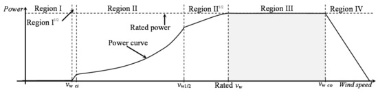
Figure 1.
Operation regions of a variable-speed, variable-pitch, horizontal-axis wind turbine.
In Region III, the wind turbine works with overrated wind speed, i.e., the value for which the machine was designed for normal operation. Therefore, the control strategy is designed to limit the rotor speed and the power. The strategy is implemented as a regulator with the rated speed as the reference signal (set point). The way to achieve this objective is to change the angle of attack of the wind with respect to the blades, affecting the aerodynamic forces acting on the blades. This effect is obtained by rotating the blades along their longitudinal axis, i.e., the blade pitching axis.
In the case of very large wind turbines, the mentioned strategy has several problems. Due to the large swept area, the wind does not have a homogeneous spatial distribution. Hence, it has impacts of different intensities on the rotor surface, causing an imbalance of forces. On the other hand, large machines have considerable inertia and, therefore, they are slow to react when the wind speed changes rapidly. The immediate consequence is that the control action must be fast, which also implies a sharp breaking when the set point is reached. This leads, on the one hand, to the occurrence of important loads and, on the other hand, introduces rapid disturbances in the thrust force, which results in vibrations in the blades and tower. Despite the effort to build the blades and other components as similar as possible, it is inevitable that there are differences between them and, as a consequence, mass imbalances are common, which also induce loads.
Finally, the control problem in the full load region is undertaken by pitch control, which in turn has to consider simultaneously regulation of rotational speed and power, rapid response in front of turbulence, damping of vibrations, and reduction of loads. The present contribution is a review of the methods proposed in the literature to address the different problems that have been mentioned previously. Thus, the second section deals with the subject of control, whose objective is the regulation of rotational speed and the different limitations and improvements. In Section 3, the problem of vibration attenuation is described, while the aspects related to load reduction are presented in Section 4. Anti-windup techniques for wind turbine control are summarized in Section 5, and some rules for the tuning of controller parameters are briefly described in Section 6. Section 7 is devoted to the low-level control of pitch actuators. Finally, conclusions are drawn in Section 8.
2. Pitch Control for Speed and Power Regulation
In variable-speed, variable-pitch machines, the rotational speed and the grid frequency are decoupled due to an indirect connection between generator and grid, which is carried out, nowadays, by the so-called back-to-back converters. This concept is about 25 years old (see [1,2,3,4,5,6]). The focus of interest in the current work is limited to pitch control.
2.1. Collective Pitch Control
Collective pitch control (CPC) is probably the oldest and most common control mechanism used to obtain smooth, regulated, and maximized energy extraction in the case of pitch variable machines. It is based on one controller, where the controlled variable is the rotational speed and the control variable is the pitch angle, which is often called the pitch command. This pitch angle is supplied to all three pitch actuators equally. Figure 2 shows the control system configuration for collective pitch control.

Figure 2.
Collective pitch control system, including the torque control loop.
Figure 2 also includes the torque control loop only for the sake of completeness. β0 is the value of the pitch angle that defines the operating point. Thus, this is the pitch angle necessary to maintain the generator speed at the rated value when the linear controller delivers a control signal equal to zero, because the controlled output has reached the set point.
2.2. Control Laws Applied to the CPC
The control system configuration is practically standard. However, the control laws used to implement the CPC can be different. The classic approach is based on PI control.
2.2.1. Standard PI/PID Controllers
A common control law applied to wind turbines is the PI/PID (proportional, integral, derivative). Thus, PID controllers have been studied and used in industry [7,8,9] as well as in academia (e.g., see [10,11,12]). The application of PID control to wind energy systems dates back to the 1970s and 1980s, as is reported, for example, in [13,14].
There are several configurations for a PID controller. The most common form used in the field of wind energy control is the parallel form [12] given by the transfer function
Kp, Ki, and Kd are the coefficients that have to be tuned in order to obtain optimal behavior. The 1/Td is the cut-off frequency for a low-pass filter that limits the high frequencies of the derivatives part. The first order low-pass filter in the derivative part is necessary for practical implementation, since a pure derivative term is a noncausal system.
2.2.2. Nonlinear PI/PID Controllers
Large-sized wind energy converters are characterized by flexible structures, nonlinearities in the pitch actuators as well as in the aerodynamics, and many operation points. Thus, standard control laws become unsatisfactory for maintaining an acceptable level of control performance. An alternative is to implement a PI/PID control system, where the controller parameters are adjusted by using nonlinear functions of the control error. This procedure is normally called NPI/NPID (Nonlinear PI/PID, see, e.g., [15,16,17]).
The control law is defined by the following:
where functions fj(e), with j = p, i, and d, are given, for instance, by the following nonlinear function:
Hence, the controller gain is given by K0 + K1, in the case of large control errors, and by K0 for small errors. K2 defines the shape of the adapting curve.
NPID approaches have successfully been used in robotics. Its use for the control of wind turbines can be found in [18,19].
2.2.3. Fractional Order PI/PID Controllers
The fractional order PID (FOPID) control, which is also known as PIνDμ with ν and μ as fractional orders, is proposed in [20]. It has been remarked in [21] that the FOPID enhances the performance of the PID control, since the fractional orders contribute two additional parameters, augmenting the possibility of tuning. Furthermore, it is more insensitive to parameter uncertainties.
FOPID control has aroused interest in academia and industry (e.g., see [22,23,24]). The anti-windup problem of FOPID is studied in [25]. The need to use gain-scheduling adaption together with FOPID is presented in [26], where the FOPID includes an anti-windup mechanism for actuators with limited magnitude is applied to a hydroelectric power station. The FOPID controller is short-formulated here, according to [27]. Starting from (1), the FOPID is obtained as a generalization by introducing fractional exponents ν and μ to the Laplace variable s; i.e.,
where (1/sγ) is an integrator with γ real and positive. A continuous integro-differential operator can be expressed as follows:
The exponent γ in (5) is negative in the control law (4). For the implementation of (5), several approximations are available (see [28,29,30]). The application of a FOPID to the collective pitch control of a large wind turbine is presented in [31].
2.2.4. Fractional Order Nonlinear PI/PID Controllers
The NPID can be combined with the FOPID in order to obtain a fractional order nonlinear PID (or PI) control (FONPID or FONPI). The control law is formulated as follows:
where the functions (f) as well as the orders, ν and μ, are defined in the previous subsections. This approach is used for the pitch control of wind turbines in [32].
2.2.5. Collective Pitch Fuzzy Control
Fuzzy control [33,34,35] is a formulation of control systems which is based on fuzzy mathematics (i.e., fuzzy sets, fuzzy logic, and fuzzy systems; see, for instance, [36,37,38]). The advantage of the approach is the possibility to introduce inaccurately and linguistically described information into a control system, whose formulation is mathematically formal. A typical fuzzy controller consists of four main components: a fuzzification interface, the inference machine, the rule base, and the defuzzification interface (see Figure 3).
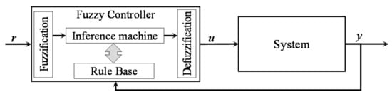
Figure 3.
Control system based on a fuzzy controller.
The collective pitch control of a wind turbine has been implemented by using a fuzzy controller many times. Some of these works are, for instance, [39,40,41,42]. In [43], the CPC combines a PID controller and a fuzzy controller. The final control law includes a fusion factor (κ), such that
When the control error is small, a large value of κ is chosen such that the focus is put on the PID in order to compensate for the steady state error. When the control error is large, κ is small, centering the attention on the fuzzy control in order to speed up the response. A similar configuration, but including a linear quadratic (LQ) controller instead of a PI, can be found in [44]. However, the last one uses controller switching and not controller fusion.
2.3. Collective Pitch Neural Control
The use of neural networks has proven to be an important tool to approximate multidimensional input–output general functions. Thus, one application field of neural networks is control system design [45,46], in particular for nonlinear systems. Therefore, it is also attractive for the implementation of pitch control of wind turbines. An important drawback of neural networks is the fact that they are not dynamic, i.e., they can only be used for the representation of static functions. Thus, the time dependence that characterizes a dynamic system has to be provided outside the neural network.
There are several architectures available for the implementation of a neural network. Radial basis function networks (RBF) [47] seem to be preferred for the implementation of control systems because they include only one hidden layer, a linear output node and a simple learning algorithm. However, multi-layer perceptrons (MLP) and deep neural networks (DNN) [48] are also applied.
The application of neural networks to the pitch control of wind turbines is distinguished by two main concepts: the direct control, i.e., the neural network is the controller, and the hybrid approach, where a classic controller, like PI or PID, is combined with the neural network, whose function is to adjust the controller parameters to the operating point in a similar way as the gain-scheduling mechanism does.
The application of neural control to pitch control of wind turbines is varied and multifaceted. Only a few relevant works are considered as examples in the following. In the case of RBF networks, it is more common to find hybrid approaches. For example, an RBF/PI configuration can be found in [49], an RBF/PID in [50], and an RBF/FOPID in [51]. The latter is a complex approach with the objective of achieving load mitigation. For the training, a set of controller gains and orders for each wind speed is used. Simulation results show some improvements. However, the approach uses a collective pitch control configuration, and, therefore, the load reduction is limited. RBF direct control approaches are also reported in the literature, as, for example, [52,53]. The last one proposed an adaptive control approach to improve the control performance. On the other hand, the pitch angles resulted in being larger.
MLP networks are used as direct controllers in [54,55]. The controller of [54] performs satisfactorily if the wind speed does not change very fast. In such a case, the pitch angles present some slow frequency oscillations. In [55], a comparison with an RBF controller is included as well. Both controllers work satisfactorily, though the RBF approach outperforms the other slightly.
Back propagation (BP) is another network architecture that can be found in the literature for both direct control [56] and hybrid control [57]. In [57], a PI controller with gain-scheduling is compared with a PI controller with a back propagation (BP) neural network. Performance results are similar with a slightly superior behavior for the BP approach.
Finally, studies based on deep neural networks have been reported recently. They can be found, for e.g., in [40,58]. Both approaches use a deep learning mechanism for wind speed estimation. This is combined in [40] with a fuzzy pitch controller and, in the second work, with a hybrid RBF/PI controller. Neural controllers based on deep neural networks are not common.
2.4. Adaption
Wind turbines are characterized by nonlinear dynamics. Hence, in order to use a linear controller, an operating point (u0, y0) must be defined, and the control system has to be set to work on it, as is shown in Figure 4. The problem with wind turbines is the fact that the operating point is not static, but changes with the wind speed, which is a stochastic variable. If the controller is optimally tuned to operate at a defined wind speed, it will experience degraded performance when the wind speed changes. Therefore, an adaptive control law is necessary (e.g., see [59,60,61] for adaptive control).
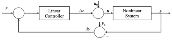
Figure 4.
Control system configuration for a nonlinear system with a linear controller.
The simplest scheme of an adaptive control system is the gain-scheduling approach. The basic idea corresponds to determining a family of operating points and for each operating point to tuning the corresponding controller. Then, an operating point detector is used to set the correct controller parameters. Thus, there are different mechanisms for parameter adaption and for the detector.
In the case of wind turbine pitch control, it is very common to tune the controller parameters for each wind speed between the rated value and the cut-out with a desired resolution, to organize the parameters in a look-up table, and to use an anemometric measurement of the wind speed to select the parameters from the look-up table. Another approach is implemented by using several controllers placed in parallel, but only one is connected to the output. Controllers are switched on according to a variable that selects the controller depending on the operating point [62]. In order to obtain a bumpless switch, the conditioning technique can be used [63]. The switching variable is a measurement or estimation of the wind speed.
Alternatively, a unique parameter sensible to the operating point changes (the scheduling parameter) is defined and the controller parameters are derived as a function of this parameter. Thus, the controller is continuously adjusted according to the variation of the scheduling parameter. In the field of wind turbine control, this is the approach used, for instance, in [64,65,66]. It is derived on the basis of a second order model of the drivetrain by using a PI controller and the pole placement approach. The scheduling parameter is the sensibility function ∂P/∂β or ∂Ta/∂β.
A more advanced approach assumes the wind turbine as a linear parameter-varying (LPV) system and the control system includes a gain-scheduling approach [67,68]. Another alternative is to use a neural network, as described in the previous subsection.
2.5. Collective Pitch Control with Maximum Power Limitation
Sometimes, power fluctuations can be important. Therefore, a protective control loop is added in [69,70]. The idea is illustrated in Figure 5, where two control loops can be observed. The former is the standard collective pitch control, and the latter is a power limiter, where the set point is the maximum design limit for the power. As a control law, PI control is often used.
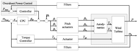
Figure 5.
Power delimiter control as additional control loop for the collective pitch control system.
2.6. Improvement by Using Feed-Forward Control
If a measurement or an estimation of the effective wind speed is available, the performance of the collective pitch control can be improved by using a feedforward approach. The control system configuration is shown in Figure 6, where is the estimation of effective wind speed or a measured value of the wind speed, which has been transferred and scaled to the center of the hub.
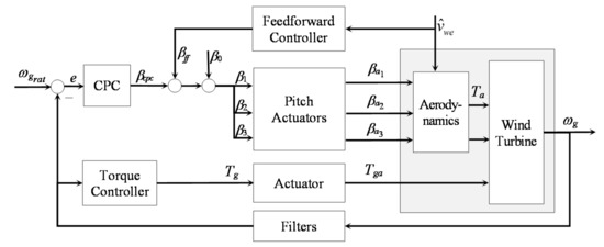
Figure 6.
Power delimiter control as additional control loop for the collective pitch control system.
The approach uses the measured or estimated disturbance to produce an anticipative control signal that is injected together with standard control action, such that the wind turbine reacts at the moment that the disturbance reaches the system [71]. In order to obtain the desired effect, the feedforward control must reach the same point in the system with the same magnitude but the opposite sign.
Feedforward control is relatively new in the field of wind turbines and both approaches, using measurements and estimations, are present in the literature. LiDAR measurements (light detection and ranging) are used, for instance, in [72,73]. Feedforward based on wind speed estimation is reported in [74,75,76]. The feedforward control is normally combined with the collective pitch control. However, the feedforward control is also combined in [77] with a CPC in a control configuration that also includes an IPC control.
2.7. Estimation of the Effectve Wind Speed
As previously described, the feedforward control requires an estimation of the wind speed. A large wind turbine has a rotor that sweeps across an extensive area. Hence, the wind speed is not uniformly distributed and also not homogeneous; therefore, a single point speed measurement, like that obtained from a nacelle anemometer, is not useful for control purposes. On the other hand, the forces caused by the wind acting on the rotor blades are transferred to the rotating shaft. The shaft integrates the forces into a torque that drives the wind turbine.
It is advantageous to find a fictitious wind speed point acting on the center of the hub, which is applied to a dynamic model of the wind turbine to produce the same power output and rotational speed as the real wind turbine under a real wind field [78]. However, the effective wind speed is not measurable and, hence, several approaches are available for its estimation.
A broad review of approaches for effective wind speed estimation is available in [79]. The most common are based on observer [80] or Kalman filters [81]—observer for an unknown input [82], immersion, and invariance estimator [83]. Other methods, such as power balance estimator [78], disturbance–adaptive control [84], and data fusion in the frequency domain [85], can also be considered. Finally, the wind speed has also been estimated by using neural networks, as is reported, for example, in [86,87,88].
2.8. Advantage and Disadvantage of the Controllers
In order to implement a collective pitch control system, any known SISO (single input–single output) control laws can be used (see, e.g., [89]). From a practical point of view, all controllers have similar performance, and the choice depends in some way on the preference, background, and expertise of the control system designer. However, there are a few aspects that can also be considered for the selection.
The wind turbine is a nonlinear system and the operating point changes with the wind speed, and, therefore, controller adaption is necessary. Classic adaptive control methods, such as self-tuning or model-reference control [59,60,61,90], appear to be too complex for the requirements, and practical experience shows that simple gain-scheduling approaches perform satisfactorily.
PI/PID control is widely used in industry and presents the additional advantage that the gain-scheduling adaption is not difficult to implement. Therefore, PID control has some favoritism in practice. The performance of the PID control can easily be improved by the NPID approach, which also includes a kind of adaption, and also by the FOPID and the FONPID. However, the improved performance takes place at the expense of a higher number of parameters; therefore, the parameter tunning is much more complex. In order to reduce the number of parameters to be tuned, the nonlinear law can be applied only to the proportional gain and the fractional order only to the integrator. Thus, the number of additional parameters is only three. Multi-objective optimization can be used (and is sometimes used) for the tuning of many parameters, but the procedure is not straightforward. In such a direction, more research effort is still necessary.
Finally, fuzzy, as well as neural, controls are also used in academia, but their small performance increase does not justify the complex implementation and tuning. However, a useful application is when the approaches are often combined with PI controls in order to implement parameter adaption, similar to the gain-scheduling mechanism. Deep neural control may be an interesting solution for future very large wind turbines, where retards, due to large inertias and high nonlinearities (due to very flexible components), render conventional control approaches ineffective.
3. Control for Compensation of the Pitching Activity
The growing need for renewable energy necessitates ever-larger wind turbines, and the stiffness reduction caused by mass limits makes the structures more flexible and, as a result, more vibration prone. Vibrations can be caused by a variety of factors in general, such as, for instance, turbulent aerodynamic loads, adverse environments, and seismically active locations. Constructive aspects like flexible high towers with a large mass at the top can also lead to important oscillations.
Since the first vibrational mode of the tower in the fore-aft direction is very low-damped, tower oscillations will appear due to the blade pitching because the pitching activity disturbs the aerodynamic thrust force [91], which in turn is transferred through the structure to the tower. All these vibrations are transferred to the blades as well [92]. A comprehensive study of wind turbine vibrations can be followed in [93,94,95,96,97,98,99,100]. The control system can also be used to attenuate large oscillations. Hence, pitch control with damping injection to reduce oscillations is analyzed in the following.
The general concept has its origin in the passivity-based energy shaping plus damping injection controller design methodology proposed for robotic manipulation [101,102,103]. The idea is to add artificial damping by superimposing a proportional term including velocity feedback into the control law. A second order model with a damping term proportional to the movement speed is normally used. The procedure can also be applied to increase the damping of the tower and blades.
3.1. Active Tower Damping Control
The control objective is to reduce tower oscillations caused by the pitching activity. This is accomplished by increasing the injection of tower damping, whose implementation is a complementary control loop. It is called active tower damping control (ATDC).
A simple integral control law is proposed in [91], which can be formulated as follows:
where ∂Ft/∂β is the sensitivity function of the thrust force in terms of the pitch angle at the operating point β0. Figure 7 shows the control system configuration.

Figure 7.
Control system configuration including an active tower damping control loop.
Figure 7 also shows the direct coupling between CPC and ATDC. This aspect has also been pointed out in [104]. Moreover, the actions of both controllers are contradictory: the CPC introduces strong pitch activity in the presence of turbulence, which in turn leads to tower oscillations; on the other hand, the ATDC reduces the fluctuations by changing the pitch angle, i.e., acting against the CPC. Therefore, the controller tuning consists of finding a compromise between both control loops. A solution to the tuning problem is proposed in [105], where the methodology is based on a cooperative game-theoretic approach. It solves the problem by using multi-objective parametric optimization and a decision maker. An effective way to solve cooperative games is to use the Pareto methods of multi-objective optimization (MOO), which can be reviewed in [106,107,108,109].
CPC and ATDC can also be combined in the same way but using more advanced control algorithms. For instance, nonlinear PID algorithms are used in [18] and fractional order PID control is studied in [31].
3.2. Active Blade Damping Control
The damping injection technique can also be used for the damping of blade tip vibrations. However, this is not a common finding in the literature. Such an idea is proposed in [110] for a collective damping of edgewise vibrations, since the edgewise mode is poorly damped with respect to the flapwise mode [111]. The control law is expressed, in terms of the tip deflection, by
where Ddb is the controller coefficient, R is the rotor radius, ωr is the rotor speed, and ωb is the speed of the blade tips. Since the difference (ωb − ωr) is not measurable, an estimation is needed. The estimation requires a model that includes this difference, such as those studied in [112].
4. Pitch Control for Load Reduction
4.1. Loads in Wind Turbines
The wind turbine is subjected to forces and moments, i.e., loads, which are transmitted through the aeroelastic couplings, affecting both the components and the machine as a whole. For instance, rotor blades are affected by bending forces that take place in the rotor plane as well as perpendicular to it. Furthermore, there are forces acting on the tower and on the nacelle that cause yaw and tilt moments that, in turn, twist and bend the tower.
Following [113], loads can be divided into five different categories. However, loads that contribute to fatigue damage in turbine structures, decreasing lifetime and increasing maintenance costs, are of special interest.
As a consequence of the periodic rotation, cyclic loads naturally appear in wind turbines. As a result, loads occur at a frequency of one per revolution, i.e., 1P, and the loads are referred to 1P loads. Hence, the symbol 1P represents the main rotational frequency (rotor angular speed), while the symbols 2P, 3P… nP correspond to the higher harmonic components of this rotor angular speed. A Fourier analysis of the forces and moments reveals that unsteady loads are centred on the 1P, 2P, etc., frequency components [114].
In particular, loads affecting the blades are focused on the 1P component with respect to the nonrotating reference frame [115]; however, on the other hand, the drivetrain, the hub and the non-rotating structure are primarily affected in the stationary reference frame by 3kP fatigue load components (with k = 1, 2, L). However, the last statement is only true when the behaviour is assumed to be linear and stationary. Contrarily, 1P components can also be found in fatigue loads affecting the drivetrain, hub, nacelle, tower, and other components [116].
As a result of the 1P loads, axial aerodynamic forces vary in every blade with a phase shift of 120 degrees. They can be observed in the flapwise bending moments and, consequently, in the rotor tilt and yaw moments. The 1P loads are caused in general by gravity, yaw misalignment, spatial turbulence and wind shear.
4.2. Indivitual Pitch Control Based on Transformation
The control objective in the full load region is not only the power limitation provided by the CPC but also the attenuation of the loads mentioned above. In order to accomplish a compromise between these two objectives, the pitch angle provided by the collective pitch control is individually adjusted for each blade. The technique is known as individual pitch control (IPC) and has been developed and improved for more than twenty years. The IPC uses the measurement of the bending moments at the rotor blade roots and the controllers provide corrections for each pitch angle.
Following the current literature, there are two different concepts for the formulation of the individual pitch control system. The former includes a transformation of the three root bending moments into two orthogonal moments and the latter is built without any transformation. Approaches that include a transformation can also be divided into two cases: approaches based on the Coleman transformation and approaches based on the Clarke transformation. In the present section, methods that include both transformations are reviewed.
The first and best investigated IPC dates from the late nineteenth century. It was first proposed in [117] and later studied and improved in [116]. The approach was inspired by the Coleman transformation, which, in turn, was first known as the Park transformation, used in electrical systems. The approach based on the Clarke transformation was developed later in [118]. The IPC can be configured either as a multi-SISO (single input–single output) control system or as a MIMO (multi input–multi output) control system. Both configurations are represented in Figure 8.
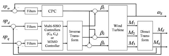
Figure 8.
General configuration of an individual pitch control system with transformations.
MIMO controllers, including the Coleman transformation for IPC, can also be found in the literature. The reason is justified because tilt and yaw moments are not really decoupled. In such cases, a multivariable control scheme can provide a better result. Several approaches have been experimented with. For instance, a linear quadratic regulator (LQR) [119], a linear quadratic Gaussian (LQG) control [116,120], and a robust control system design [77,104] are reported in the literature.
4.3. Indivitual Pitch Control without Transformation
The name individual blade control (IBC) (see [115,121,122]) was coined to refer to a control system that uses a multi-SISO approach that does not include transformations. It is based on three single controllers, assuming that all three moments are decoupled. In [123], the different approaches to the IPC are compared. While MIMO control without transformation is also possible, it has not been implemented so far. The control scheme for the IPC without transformation is illustrated in Figure 9.
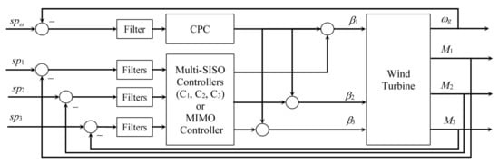
Figure 9.
Control system configuration of the IPC without transformation.
4.4. Control Laws Applied to the IPC
The classic IPC with Coleman transformation uses two standard PI controllers as given in (1), but with Kd equal to zero. This configuration is improved in [19] by using NPI control and in [32] by using FONPI control. In [124], the PI controllers of the IPC are combined with a radial basis function neural network such that the PI controllers are better adapted to the nonlinearities. The results show an important improvement in the load reduction.
In the case of IPC with Clarke transformation, the used control law is the proportional resonant (PR) controller proposed in [125] and given by the following:
where Kk are the individual resonant gains and the index k corresponds to the harmonics 1P, 2P, etc.
The individual blade control, as proposed in [122], is a multi-SISO control system, where the individual SISO controllers can be implemented by using any available control law. However, concrete control algorithms are not mentioned in the literature.
4.5. Analysis and Discusion of the Different Control Schemesfor IPC
Different approaches for the IPC have been developed for the same objective, but the concepts are not equivalent. Embedding the Coleman transformation in the control law, a full coupled MIMO controller is obtained, where the diagonal elements of the transfer matrix are proportional resonant transfer functions as given in (10). All the other six elements are also transfer functions. By embedding the Clarke transformation, a symmetric full transfer matrix with resonant transfer functions in all elements is obtained. Thus, both MIMO controllers are different. While the azimuth angle must be measured in the approach with the Coleman transformation, it is not required for the Clarke transformation or the IBC.
On the other hand, the IBC has a simplified diagonal structure, ignoring cross-coupling interactions. On the other hand, the load information of each individual blade is maintained, something that is lost in the case of approaches with transformation; therefore, the IBC is more flexible to select the loads to be reduced. The cost of this flexibility is the additional controller and the impossibility of considering the blade interactions.
5. Anti-Windup Techniques for Pitch Control
5.1. Classic Anti-Windup Techniques
Controllers with integral action require a technique to avoid the windup of the integrator. With respect to PID control, anti-windup mechanisms have been studied in depth for a long time (see, for instance, [126,127,128]). In the following, the problem is considered for a controller, such that it is valid for the whole family of PID control laws. On the other hand, an anti-windup strategy for the FOPID is described in [25].
For the conventional parallel representation of the PID controller, an important strategy is represented by the back-calculation approach, which is proposed in [129] and shown in Figure 10.

Figure 10.
Fractional order nonlinear PID controller with back-calculation anti-windup approach.
The controller can be formulated in the automatic reset configuration, for which a very simple anti-windup strategy is described in [12]. This is also presented in [130] as an external reset. The scheme is presented in Figure 11.

Figure 11.
Automatic reset configuration with separated integrators and anti-windup strategy.
This strategy has the disadvantage that no parameter is available to tune the anti-windup reaction. Therefore, the configuration is modified in [31], as shown in Figure 12, such that a back-calculation strategy is obtained.
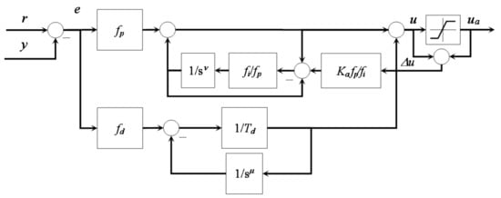
Figure 12.
Back calculation technique embedded in the automatic reset configuration.
5.2. Anti-Windup Techniques for Magnitude and Rate Limitations
The anti-windup mechanisms described above work correctly in the case of actuators with magnitude saturation. However, some actuators, such as, for example, the pitch actuators of wind turbines, are not only limited in magnitude, but also in rate. Hence, an anti-windup mechanism for magnitude and rate limitations is necessary.
It is pointed out in [130] that the external reset scheme appears to change the rate at which the error is integrated, allowing integral action to match the speed of the actuator. This is also correct for the schemes of Figure 13.

Figure 13.
Modified automatic reset configuration for magnitude and rate with back calculation.
5.3. Anti-Windup Technique for Fractional Order Controller
In [25], an anti-windup scheme for FOPID is proposed. The idea is to change the order of the derivative action from μ to σ > 1, when the actuator saturates, such that the derivative action becomes more aggressive, and the control variable leaves the saturation state more abruptly. The concept is illustrated in Figure 14.

Figure 14.
Anti-windup concept taking advantage of the fractional order approach.
5.4. Anti-Windup Technique for the Collective Pitch Control
In the case of the CPC, the problem is given by the fact that there are three nonidentical actuators that can independently saturate only one controller. Although the problem is important, it is seldom treated in the literature. The approach presented here follows [31]. The idea is to fuse the three different signals, ∆βi, into one and to lead the results to the anti-windup scheme. The average value of the following:
of the three variables can be applied if the three actuators are similar. On the other hand, the worst-case strategy can be used when the differences are important. Due to the fact that the pitch angles in full load operation fluctuate between −3 and 25 degrees, the actuators do not saturate in the negative range. Consequently, the differences (∆β) are always negative or zero for all actuators, i.e., ∆βi ≤ 0, ∀i. For the worst-case strategy, the largest negative difference (maximum saturation) is led to the anti-windup mechanism, i.e.,
The anti-windup concept for the CPC is given in Figure 15. The anti-windup mechanism used is presented in Figure 13 or Figure 14.

Figure 15.
Anti-windup strategy for the collective pitch control.
5.5. Anti-Windup Technique for the Individual Pitch Control
In the case of the individual pitch control, the anti-windup mechanism is more complex. Only some approaches have been proposed in [32,131,132]. The problem includes two dimensions: on one hand, controllers and actuators are separated by the inverse Coleman transformation and, on the other hand, there are two controllers and three actuators. Moreover, the actuators share the IPC and the CPC. Thus, the anti-windup strategy should include not only the IPC but also the CPC.
The solution presented here follows [32]. The solution considers first a virtual actuator, i.e., an actuator with an input only for the IPC control variable βipc,i, or in other words, an actuator with an output reduced by the factor (β0 + βcpc), i.e.,
The differences in ∆βipc,i are computed in the non-rotating frame and the controllers are in the rotating frame. As a result, the differences must be transferred to the rotating coordinating system by means of a direct Coleman transformation. Since the Coleman transformation does not preserve the sign, the anti-windup mechanisms must become active when ∆βi < 0 for any i, where the outputs of the Coleman transformation (noted ∆βd and ∆βq) should also be negative. This is obtained by using the following:
The strategy is illustrated in Figure 16.
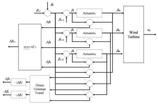
Figure 16.
Anti-windup strategy for the whole pitch control system (CPC and IPC).
6. Parameter Tuning for the Pitch Control with Multi-SISO Controllers
As it was shown in the previous sections, the whole pitch control system consists of several control loops and many controllers, which are in general coupled. Hence, it is desired to tune all controllers considering the interactions and contradictory objectives. An approach for obtaining this is proposed in [133]. It is based on the consideration that all control loops are players in a cooperative differential game [134,135,136], whose solution is provided by a multi-objective optimization problem.
Multi-objective optimization, which is also known as multi-performance, multi-criteria, or vector optimization, was introduced by [137] and many algorithms can be used. Some of them are the NBI (normal boundary intersection [138]), NSGA II (non-dominated sorting genetic algorithm [139]), MOPSO (multi-objective particle swarm optimization [140]), SPEA 2 (strength pareto evolutionary algorithm [141]), NBIm (modified NBI [142]), DSD (directed search domain [143]), MOACO (multi-objective artificial ant colony optimization [144]), MOABC (multi-objective artificial bee colony algorithm [145]), MOBA (multi-objective bat algorithm [146]), DSD II (second version of DSD [143]), NSGA-III (third generation of NSGA, [147]), MOGWO (multi-objective grey wolf optimization [148]), MOM-VO (multi-objective multi-verse optimization [149]), and MOALO (multi-objective ant lion optimization [150]).
The application of this method, based on parametric multi-objective optimization to pitch control, has been reported in [105,110,151,152,153].
7. Low-Level Control of Pitch Actuators
Pitch actuators are modelled by using different levels of complexity. For instance, the pitch subsystem is represented by a first order system in [154,155,156]. Pitch actuators are normally represented by a simple linear model. However, real pitch actuator components have an embedded additional controller.
7.1. Models of Pitch Actuators without Control
In particular, an electromechanical actuator is modelled as a first order system in [157], according to the following:
where β is the pitch angle and βref is the set point defined as a pitch angle. The pitch angle and the pitch rate are also constrained by the following:
It should be remarked that the maximum amplitude constraint, βmax, for the pitch angle, when the wind speed is overrated, is defined as the necessary pitch angle to maintain a rated rotor speed at the maximum permitted wind speed. On the other hand, βmax is set at 90° during the shutdown operation. A graphical representation of the model is presented in Figure 17.
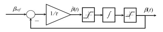
Figure 17.
Model representation of a first order pitch actuator without controller and pitch angle set point.
Some pitch actuators work with a pitch rate set point, i.e., . In such a situation, the block diagram of Figure 17 has to be modified to accept pitch rate set points. This change is illustrated in Figure 18.
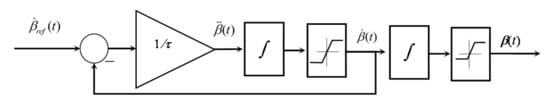
Figure 18.
First order model of the pitch actuator with pitch rate set point.
Second order linear models are used to describe pitch actuators (see, e.g., [158,159,160,161]). Moreover, the second order models can be complemented, as in [162,163], by a dead time Tt. A general second order approach can be described by
with the same constraints as for the first order model, i.e.,
The corresponding block diagram is given in Figure 19.
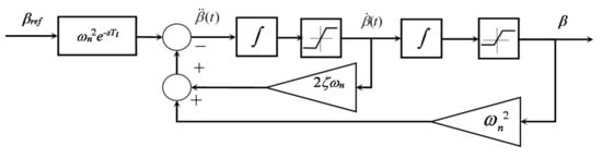
Figure 19.
Pitch actuator model based on a second order system with dead time.
7.2. Models of Pitch Actuators with Control
Pitch actuators normally have an embedded controller. Assuming a PI controller in the pitch actuator control system. The block diagrams change as given in Figure 20 for the first order actuator and in Figure 21 for the second order actuator.
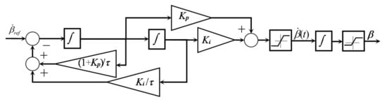
Figure 20.
First order pitch actuator with PI control and pitch rate set point.
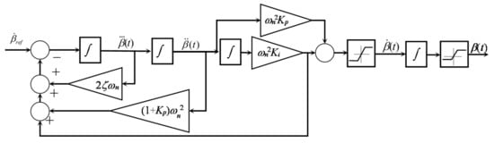
Figure 21.
Second order pitch actuator with PI control and pitch rate set point.
7.3. Pitch Actuators with Fault-Tolerant Control
Fault-tolerant control (e.g., see [164,165]) is a concept whose origin goes back to the birth of safe critical systems, which are not allowed to fail, e.g., an aircraft. Nowadays, the idea has been extended to other kinds of systems, including wind turbines (see [166] for review). The main idea is to define an alternative mission for the system with a finite completion time. This mission has to be fulfilled by the system in the case that a fault occurs. The execution of the mission allows, on one hand, to avoid the crash and, on the other hand, to organize maintenance arrangements and to plan the shutdown, in order to reduce the downtime.
The performance improvement of the pitch control system normally requires major pitching activity leading to increased wear of the pitch actuators. Since actuators and sensors of wind turbines are also prone to faults [167,168], it is expected that pitch actuators will become a weak point in normal operation. For this reason, several concepts for fault tolerant control (FTC) for pitch actuators have been studied.
Pitch actuators are divided into hydraulic and electric systems. The wind energy large converter market has been dominated by hydraulic pitch actuation. They are compact, have a rapid response, and have a high pitching torque. The main disadvantages are the nonlinear behaviour and the hybrid nature (hydraulic power source with electrical control and sensing). The pitch actuator has bias error because of oil leakage in the hydraulic piston, as well as the pitch actuator getting stuck, caused by valve blockage in the hydraulic actuation system, are the most common faults. They are also the most intensely treated cases of fault-tolerant control of pitch actuators (see, for instance, [169,170]).
On the other hand, electric actuators have progressively been adopted because of their simple drive architecture, high reliability, and a unified electric system for power source, sensing, and control. They also have large inertia and the intensive pitching activity can cause overheating and damage. A fault-tolerant control approach for an electrical pitch actuator has been proposed in [171]. However, this field should be studied more exhaustively.
8. Conclusions
The pitch control system is essential, not only for high energy conversion, but also to guarantee a long lifetime of very large wind turbines. In the past twenty years, many control objectives, approaches, and particular techniques have been proposed in order to solve the control problems with which wind energy technology has challenged control engineering. The present review intends to put into context the multifaceted aspects related to the pitch control of wind energy converters and highlight different solutions contributed by the research community.
Performance improvement, prolongation of lifetime, and reduction of vibrations are the main facets of wind turbines. These three aspects are analyzed separately in the work, showing the available approaches for each case. In general, different control schemes for the same control objective perform similarly. Thus, the choice depends on control system designers, where their background, experience, and preferences play an important role.
Control laws more complex than PI/PID normally improve control performance. For instance, FONPI control improves the performance of IPC. However, the implementation and tuning require additional effort that sometimes is not justified in the analysis of the final balance. Moreover, anti-windup mechanisms are essential for all controllers that include integral action. Intelligent control techniques are seldom applied in practice. However, standard techniques will provide limited performance in the case of very large flexible wind turbines. In such a case, intelligent control might become important as a possible solution. Fault-tolerant control of pitch actuators is practically not considered at present, but it is an important concept to increase the reliability of large machines.
Another factor to consider is the fact that very large wind turbines need control for all the objectives presented. Hence, CPC, IPC, ATDC, and ABDC should be included in the integrated control system. A summary of the control objective and approaches are presented in Table 1.

Table 1.
Summary of methods used for the pitch control of large wind turbines.
Funding
This work has been financed by the Federal Ministry of Economic Affairs and Energy (BMWi).
Conflicts of Interest
The author declares no conflict of interest.
References
- McIver, A.; Holmes, D.G.; Freere, P. Optimal control of a variable speed wind turbine under dynamic wind conditions. In Proceedings of the 1996 IEEE Industry Applications Conference Thirty-First IAS Annual Meeting, San Diego, CA, USA, 6–10 October 1996; pp. 1692–1698. [Google Scholar]
- Zinger, D.S.; Muljadi, E.; Miller, A. A simple control scheme for variable speed wind turbines. In Proceedings of the 1996 IEEE Industry Applications Conference Thirty-First IAS Annual Meeting, San Diego, CA, USA, 6–10 October 1996; pp. 1613–1618. [Google Scholar]
- Leithead, W.E.; Connor, B. Control of variable speed wind turbines: Design task. Int. J. Control 2000, 73, 1189–1212. [Google Scholar] [CrossRef]
- Muljadi, E.; Butterfield, C.P. Pitch-controlled variable-speed wind turbine generation. IEEE Trans. Ind. Appl. 2001, 37, 240–246. [Google Scholar] [CrossRef] [Green Version]
- Ackermann, T.; Söder, L. An overview of wind energy-status 2002. Renew. Sustain. Energy Rev. 2002, 6, 67–128. [Google Scholar] [CrossRef]
- Sahin, D.A. Progress and recent trends in wind energy. Prog. Energy Combust. Sci. 2004, 30, 501–543. [Google Scholar] [CrossRef]
- McMillan, G.K. Industrial Applications of PID Control. In PID Control in the Third Millennium; Vilanova, R., Visioli, A., Eds.; Springer: London, UK, 2012; pp. 415–461. [Google Scholar]
- Blevins, T.L. PID advances in industrial control. IFAC Proc. Vol. 2012, 45, 23–28. [Google Scholar] [CrossRef] [Green Version]
- Liu, G.P.; Daley, S. Optimal-tuning PID control for industrial systems. Control. Eng. Pract. 2001, 9, 1185–1194. [Google Scholar] [CrossRef]
- Åström, K.J.; Hagglund, T. Advanced PID Control; ISA—The Instrumentation, Systems and Automation Society: Research Triangle Park, NC, USA, 2005. [Google Scholar]
- Johnson, M.A.; Moradi, M.H. PID Control—New Identification and Design Methods; Springer: London, UK, 2005. [Google Scholar]
- Visioli, A. Practical PID Control; Springer: London, UK, 2006. [Google Scholar]
- Kos, J.M. On line control of a large horizontal axis energy conversion system and its performance in a turbulent wind environment. In Proceedings of the 13th Intersociety Energy Conversion Engineering Conference, San Diego, CA, USA, 20–25 August 1978; pp. 2064–2073. [Google Scholar]
- Wasynczuk, O.; Man, D.T.; Sullivan, J.P. Dynamic behavior of a class of wind turbine generators during random wind fluctuations. IEEE Trans. Power Appar. Syst. 1981, PAS-100, 2837–2845. [Google Scholar] [CrossRef]
- Shahruz, S.M.; Schwartz, A.L. Design of optimal nonlinear PI compensators. In Proceedings of the IEEE Conference on Decision and Control, San Antonio, CA, USA, 15–17 December 1993; pp. 3564–3565. [Google Scholar]
- Xu, Y.; Hollerbach, J.M.; Ma, D. A nonlinear PD controller for force and contact transient control. IEEE Control. Syst. Mag. 1995, 15, 15–21. [Google Scholar]
- Isayed, B.M.; Hawwa, M.A. A nonlinear PID control scheme for hard disk drive servosystems. In Proceedings of the 15th Mediterranean Conference on Control and Automation, Athens, Greece, 27–29 June 2007; pp. 1–6. [Google Scholar]
- Gambier, A.; Nazaruddin, Y. Collective pitch control with active tower damping of a wind turbine by using a nonlinear PID approach. IFAC–PaperOnline 2018, 51, 238–243. [Google Scholar] [CrossRef]
- Gambier, A.; Nazaruddin, Y. Nonlinear PID control for pitch systems of large wind energy converters. In Proceedings of the 2018 IEEE Conference on Control Technology and Applications, Copenhagen, Denmark, 21–24 August 2018; pp. 996–1001. [Google Scholar]
- Podlubny, I. Fractional-order systems and piλdμ-controllers. IEEE Trans. Autom. Control. 1999, 44, 208–214. [Google Scholar] [CrossRef]
- Ranganayakulu, R.; Uday Bhaskar Babu, G.; Seshagiri Rao, A.; Shikchand Patle, D. A comparative study of fractional order PIλ/PIλDμ tuning rules for stable first order plus time delay processes. Resour. Effic. Technol. 2016, 2, 136–152. [Google Scholar] [CrossRef]
- Chevalier, A.; Francis, C.; Copot, C.; Ionescu, C.; de Keyser, R. Fractional-order PID design: Towards transition from state-of- art to state-of-use. ISA Trans. 2019, 84, 178–186. [Google Scholar] [CrossRef] [PubMed]
- Efe, M.O. Fractional order systems in industrial automation—A survey. IEEE Trans. Ind. Inf. 2011, 7, 582–591. [Google Scholar] [CrossRef]
- Monje, C.A.; Vinagre, B.M.; Feliu, V.; Chen, Y.Q. Tuning and autotuning of fractional order controllers for industry applications. Control. Eng. Pract. 2008, 16, 798–812. [Google Scholar] [CrossRef] [Green Version]
- Padula, F.; Visioli, A.; Pagnoni, M. On the anti-windup schemes for fractional-order PID controllers. In Proceedings of the 2012 IEEE 17th International Conference on Emerging Technologies & Factory Automation, Krakow, Poland, 17–21 September 2012; pp. 1–4. [Google Scholar]
- Rosas-Jaimes, O.A.; Munoz-Hernandez, G.A.; Mino-Aguilar, G.; Castaneda-Camacho, J.; Gracios-Marin, C.A. Evaluating fractional PID control in a nonlinear MIMO model of a hydroelectric power station. Hindawi-Wiley 2019, 2019, 9367291. [Google Scholar] [CrossRef]
- El-Khazali, R. Fractional-order PIλDμ controller design. Comput. Math. Appl. 2013, 66, 639–646. [Google Scholar] [CrossRef]
- Oustaloup, A.; Sabatier, J.; Lanusse, P.; Malti, R.; Melchior, P.; Moreau, X.; Moze, M. An overview of the CRONE approach in system analysis, modeling and identification, observation and control. IFAC Proc. Vol. 2008, 41, 10–13. [Google Scholar] [CrossRef] [Green Version]
- Carlson, G.E.; Halijak, C.A. Approximation of fractional capacitors (1/s)1/n by a regular Newton process. IEEE Trans. Circuit Theory 1964, 7, 210–213. [Google Scholar] [CrossRef]
- Vinagre, B.M.; Podlubny, I.; Hernandez, A.; Feliu, V. Some approximations of fractional order operators used in control theory and applications. Fract. Calc. Appl. Anal. 2000, 3, 231–248. [Google Scholar]
- Wang, X.; Gambier, A.; Vinagre, B. Fractional Order PID Control with Rate-limited Anti-windup for the Pitch System of Wind Turbines. In Proceedings of the 2020 IEEE Conference on Control Technology and Applications, Montreal, QC, Canada, 24–26 August 2020; pp. 933–938. [Google Scholar]
- Wang, X.; Gambier, A. Individual pitch control of a large wind turbine using a fractional order nonlinear PI approach with anti-windup strategy. In Proceedings of the 2021 IEEE Conference on Control Technology and Applications, San Diego, CA, USA, 8–11 August 2021; pp. 289–294. [Google Scholar]
- Shaw, I.S. Fuzzy Control of Industrial Systems: Theory and Application; Springer Science+Business Media, LLC: New York, NY, USA, 1998. [Google Scholar]
- Jantzen, J. Foundations of Fuzzy Control, 2nd ed.; John Wiley & Sons: Chichester, UK, 2013. [Google Scholar]
- Hooda, D.S.; Raich, V. Fuzzy Logic Models: An Introduction; Alpha Science International: Oxford, UK, 2017. [Google Scholar]
- Hanss, M. Applied Fuzzy Arithmetic; Springer: Berlin, Germany, 2005. [Google Scholar]
- Pedrycz, W.; Gomide, F. Fuzzy Systems Engineering; John Wiley & Sons: Hoboken, NY, USA, 2007. [Google Scholar]
- Ross, T.J. Fuzzy Logic with Engineering Applications, 3rd ed.; John Wiley & Sons: Chichester, UK, 2010. [Google Scholar]
- Sahoo, S.; Subudhi, B.; Panda, G. Torque and pitch angle control of a wind turbine using multiple adaptive neuro-fuzzy control. Wind. Eng. 2020, 44, 125–141. [Google Scholar] [CrossRef]
- Sierra-Garcia, J.E.; Santos, M. Deep learning and fuzzy logic to implement a hybrid wind turbine pitch control. Neural Comput. Appl. 2021, 1–15. [Google Scholar] [CrossRef]
- Zhang, X.; Wang, W.; Liu, Y. Fuzzy control of variable speed wind turbine. In Proceedings of the 6th World Congress on Intelligent Control and Automation, Dalian, China, 21–23 June 2006; pp. 3872–3876. [Google Scholar]
- Gong, X.; Li, W. Wind turbine fuzzy logic individual pitch control based on chaotic optimization. Earth Environ. Sci. 2018, 146, 012063. [Google Scholar] [CrossRef] [Green Version]
- Guo, R.; Du, J.; Wu, J.; Liu, Y. The pitch control algorithm of wind turbine based on fuzzy control and PID control. Energy Power Eng. 2013, 5, 6–10. [Google Scholar] [CrossRef]
- Viveiros, C.; Melício, R.; Igreja, J.M.; Mendesb, V.M.F. Supervisory control of a variable speed wind turbine with doubly fed. Energy Rep. 2015, 1, 89–95. [Google Scholar] [CrossRef] [Green Version]
- Pham, D.T.; Liu, X. Neural Networks for Identification, Prediction and Control; Springer: London, UK, 1995. [Google Scholar]
- Schiff, S.J. Neural Control Engineering; MIT Press: Cambridge, MA, USA, 2012. [Google Scholar]
- Liu, J. Radial Basis Function (RBF) Neural Network Control for Mechanical Systems; Springer: Berlin/Heidelberg, Germany, 2013. [Google Scholar]
- Aggarwal, C.C. Neural Networks and Deep Learning: A Textbook; Springer: Cham, Switzerland, 2018. [Google Scholar]
- Poultangari, I.; Shahnazi, R.; Sheikhan, M. RBF neural network based PI pitch controller for a class of 5-MW wind turbines using particle swarm optimization algorithm. ISA Trans. 2012, 51, 641–648. [Google Scholar] [CrossRef] [PubMed]
- Yao, X.; Su, X.; Tian, L. Pitch angle control of variable pitch wind turbines based on neural network PID. In Proceedings of the 4th IEEE Conference on Industrial Electronics and Applications, Xi’an, China, 25–27 May 2009; pp. 3235–3239. [Google Scholar]
- Asgharnia, A.H.; Jamali, A.; Shahnazi, R.; Maheri, A. Load mitigation of a class of 5-MW wind turbine with RBF neural network based fractional-order PID controller. ISA Trans. 2020, 96, 272–286. [Google Scholar] [CrossRef]
- El-Mjabber, E.-K.; El Hajjaji, A.; Khamlichi, A. Analysis of a RBF neural network based controller for pitch angle of variable speed wind turbines. Procedia Eng. 2017, 181, 552–559. [Google Scholar] [CrossRef]
- Jafarnejadsani, H.; Pieper, J.; Ehlers, J. Adaptive control of a variable-speed variable-pitch wind turbine using radial-basis function neural network. IEEE Trans. Control. Syst. Technol. 2013, 21, 2264–2272. [Google Scholar] [CrossRef]
- Kang, M.-J.; Kim, H.-C. Neural Network Based Pitch Controller. In Proceedings of the World Congress on Electrical Engineering and Computer Systems and Science, Barcelona, Spain, 13 July 2015; pp. 140–146. [Google Scholar]
- Yilmaz, A.S.; Özer, Z. Pitch angle control in wind turbines above the rated wind speed by multi-layer perceptron and radial basis function neural networks. Expert Syst. Appl. 2009, 36, 9767–9775. [Google Scholar] [CrossRef]
- Ro, K.; Choi, H.-h. Application of neural network controller for maximum power extraction of a grid-connected wind turbine system. Electr. Eng. 2005, 88, 45–53. [Google Scholar] [CrossRef]
- Du, J.; Wang, B. Pitch control of wind turbines based on BP neural network. J. Phys. Conf. Ser. 2020, 1678, 012060. [Google Scholar] [CrossRef]
- Jie, W.; Jingchun, C.; Lin, Y.; Wenliang, W.; Jian, D. Pitch control of wind turbine based on deep neural network. IOP J. Conf. Ser. 2020, 619, 012034. [Google Scholar] [CrossRef]
- Åström, K.J.; Wittenmark, B. Adaptive Control, 2nd ed.; Dover Publications: New York, NY, USA, 2008. [Google Scholar]
- Chalam, V.V. Adaptive Control Systems: Techniques and Applications; Marcel Dekker: New York, NY, USA, 1987. [Google Scholar]
- Tao, G. Adaptive Control Design and Analysis; John Wiley & Sons: Hoboken, NY, USA, 2003. [Google Scholar]
- Liberzon, D. Switching in Systems and Control; Birkhäuser: Boston, MA, USA, 2003. [Google Scholar]
- Hanus, R. A new technique for preventing control windup. J. A 1980, 21, 15–20. [Google Scholar]
- Leithead, W.E.; Leith, D.J.; Hardan, F.; Markou, H. Global gain-scheduling control for variable speed wind turbines. In Proceedings of the European Wind Energy Conference, Nice, France, 1–5 March 1999; pp. 853–856. [Google Scholar]
- Tibaldi, C.; Hansen, M.H.; Henriksen, L.C.; Bak, C. Effects of gain-scheduling methods in a classical wind turbine controller on wind turbine aero-servo-elastic modes and loads. In Proceedings of the 32nd ASME Wind Energy Symposium, National Harbor, MD, USA, 13–17 January 2014; pp. 1–12. [Google Scholar]
- Hansen, M.H.; Hansen, A.; Larsen, T.J.; Øye, S.; Sørensen, P.; Fuglsang, P. Control Design for a Pitch-Regulated, Variable Speed Wind Turbine; Technical Report; Risø National Laboratory: Roskilde, Denmark, 2005. [Google Scholar]
- Díaz de Corcuera, A.; Pujana-Arrese, A.; Ezquerra, J.M.; Milo, A.; Landaluze, J. Linear models-based LPV modelling and control for wind turbines. Wind. Energy 2015, 18, 1151–1168. [Google Scholar] [CrossRef]
- Shan, W.W. Gain Scheduling Pitch Control for Fatigue Load Reduction for Wind Turbines; Fraunhofer Verlag: Stuttgart, Germany, 2016. [Google Scholar]
- Perdana, A. Dynamic Models of Wind Turbines. Ph.D. Thesis, Chalmers University of Technology, Göteborg, Sweden, 2008. [Google Scholar]
- Shahidehpour, M.; Eremia, M. Wind power generation. In Handbook of Electrical Power System Dynamics: Modeling, Stability, and Control; John Wiley & Sons: Hoboken, NY, USA, 2013; pp. 179–228. [Google Scholar]
- Goodwin, G.C.; Graebe, S.F.; Salgado, M.E. Control System Design; Prentice Hall: Upper Saddle River, NY, USA, 2001. [Google Scholar]
- Scholbrock, A.; Fleming, P.; Fingersh, L.; Wright, A.; Schlipf, D.; Haizmann, F.; Belen, F. Field testing LIDAR based feed-forward controls on the NREL controls advanced research turbine. In Proceedings of the 51st AIAA Aerospace Sciences Meeting Including the New Horizons Forum and Aerospace Exposition, Dallas, TX, USA, 7–10 January 2013; pp. 1–8. [Google Scholar]
- Park, H.-S.; Chang, P.H.; Lee, D.Y. Continuous zero phase error tracking controller with gain error compensation. In Proceedings of the American Control Conference, San Diego, CA, USA, 2–4 June 1999; pp. 3554–3558. [Google Scholar]
- Nam, Y.; Kimt, J.; Paek, l.; Moon, Y.-H.; Kim, S.-J.; Kim, D.-J. Feedforward pitch control using wind speed estimation. J. Power Electron. 2011, 11, 211–217. [Google Scholar] [CrossRef]
- Jiao, X.; Yang, Q.; Zhu, C.; Fu, L.; Chen, Q. Effective wind speed estimation and prediction based feedforward feedback pitch control for wind turbines. In Proceedings of the 12th Asian Control Conference (ASCC), Kitakyusyu, Japan, 9–12 June 2019; pp. 799–804. [Google Scholar]
- Taruffi, F.; Fontanella, A.; Muggiasca, S.; Di Carlo, S.; Belloli, M. Numerical design of a wind observer and feedforward control of wind turbines. J. Phys. Conf. Ser. 2020, 1452, 012003. [Google Scholar] [CrossRef] [Green Version]
- Ungurán, R.; Petrovic, V.; Boersma, S.; van Wingerden, J.-W.; Pao, L.Y.; Kühn, M. Feedback-feedforward individual pitch control design for wind turbines with uncertain measurements. In Proceedings of the 2019 American Control Conference, Philadelphia, PA, USA, 10–12 July 2019; pp. 4151–4158. [Google Scholar]
- Van der Hooft, E.L.; Engelen, T.G. Estimated wind speed feed forward control for wind turbine operation optimisation. In Proceedings of the European Wind Energy Conference and Exhibition, London, UK, 22–25 November 2004; pp. 1–9. [Google Scholar]
- Jena, D.; Rajendran, S. A review of estimation of effective wind speed based control of wind turbines. Renew. Sustain. Energy Rev. 2015, 43, 1046–1062. [Google Scholar] [CrossRef]
- Østergaard, K.Z.; Brath, P.; Stoustrup, J. Estimation of effective wind speed. J. Phys. Conf. Ser. 2007, 75, 012082. [Google Scholar] [CrossRef] [Green Version]
- Najafi Khoshrodi, M.; Jannati, M.; Sutikno, T. A review of wind speed estimation for wind turbine systems based on Kalman filter technique. Int. J. Electr. Comput. Eng. 2016, 6, 1406–1411. [Google Scholar]
- Odgaard, P.F.; Damgaard, C.; Nielsen, R. Unknown input observer based estimation of wind speed for wind turbines control. In Proceedings of the 18th IFAC World Congress, Milan, Italy, 28 August–2 September 2011; pp. 1698–1703. [Google Scholar]
- Ortega, R.; Mancilla-David, F.; Jaramillo, F. A globally convergent wind speed estimator for wind turbine systems. Int. J. Adapt. Control. Signal Process. 2013, 27, 413–425. [Google Scholar] [CrossRef]
- Wrigth, A.D. Modern Control Design for Flexible Wind Turbines; National Renewable Energy Laboratory: Golden, CO, USA, 2004. [Google Scholar]
- Xu, Z.; Hu, Q.; Ehsani, M. Estimation of effective wind speed for fixed-speed wind turbines based on frequency domain data fusion. IEEE Trans. Sustain. Energy 2012, 3, 57–64. [Google Scholar] [CrossRef]
- Barambones, O.; Gonzalez de Durana, J.M.; Kremers, E. A Neural Network Based Wind Speed Estimator for a Wind Turbine Control. In Proceedings of the 15th IEEE Mediterranean Electrotechnical Conference, Valletta, Malta, 26–28 April 2010; 2010. [Google Scholar]
- Jaramillo-Lopez, F.; Kenné, G.; Lamnabhi-Lagarrigue, F. A novel online training neural network-based algorithm for wind speed estimation and adaptive control of PMSG wind turbine system for maximum power extraction. Renew. Energy 2016, 86, 38–48. [Google Scholar] [CrossRef]
- Sardar Maran, P.; Ponnusamy, R. Neural network based wind speed estimation and wind energy prediction. Eur. J. Sci. Res. 2013, 95, 324–331. [Google Scholar]
- Isermann, R. Digital Control Systems, 2nd ed.; Springer: Berlin, Germany, 1989. [Google Scholar]
- Nguyen, N.T. Model-Reference Adaptive Control; Springer: Cham, Switzerland, 2018. [Google Scholar]
- Bossanyi, E.A. Wind turbine control for load reduction. Wind Energy 2003, 6, 229–244. [Google Scholar] [CrossRef]
- Murtagh, P.J.; Basu, B.; Broderick, B.M. Along-wind response of a wind turbine tower with blade coupling. Eng. Struct. 2005, 27, 1209–1219. [Google Scholar] [CrossRef]
- Arrigan, J.; Huang, C.; Staino, A.; Basu, B.; Nagarajaiah, S. A frequency tracking semi-active algorithm for control of edgewise vibrations in wind turbine blades. Smart Struct. Syst. 2014, 13, 177–201. [Google Scholar] [CrossRef]
- Fitzgerald, B.; Basu, B. Vibration control of wind turbines: Recent advances and emerging trends. Int. J. Sustain. Mater. Struct. Syst. 2020, 4, 347–372. [Google Scholar] [CrossRef]
- Rezaee, M.; Aly, M.A. Vibration control in wind turbines to achieve desired system-level performance under single and multiple hazard loadings. Struct. Control. Health Monit. 2018, 25, e2261. [Google Scholar] [CrossRef]
- Xie, F.; Aly, A.-M. Structural control and vibration issues in wind turbines: A review. Eng. Struct. 2020, 210, 110087. [Google Scholar] [CrossRef]
- Zhao, X.; Weiss, G. Suppression of the vibrations of wind turbine towers. IMA J. Math. Control. Inf. 2011, 28, 377–389. [Google Scholar] [CrossRef]
- Zuo, H.; Bi, K.; Hao, H. A state-of-the-art review on the vibration mitigation of wind turbines. Renew. Sustain. Energy Rev. 2020, 121, 109710. [Google Scholar] [CrossRef]
- Han, Q.; Wei, J.; Han, Q.; Zhang, H. Dynamics and Vibration Analyses of Gearbox in Wind Turbine; Springer Nature: Singapore, 2017. [Google Scholar]
- Barszcz, T. Vibration-Based Condition Monitoring of Wind Turbines, 1st ed.; Springer Nature: Cham, Switzerland, 2019. [Google Scholar]
- Takegaki, M.; Arimoto, S. A new feedback method for dynamic control of manipulators. J. Dyn. Syst. Meas. Control. 1981, 103, 119–125. [Google Scholar] [CrossRef]
- Stramigioli, S. Creating artificial damping by means of damping injection. In Proceedings of the 1996 ASME International Mechanical Engineering Congress and Exposition, Atlanta, GA, USA, 17–22 November 1996; pp. 601–606. [Google Scholar]
- Ortega, R.; Spong, M.W. Adaptive motion control of rigid robots: A tutorial. Automatica 1989, 25, 877–888. [Google Scholar] [CrossRef]
- Shan, M. Load Reducing Control for Wind Turbines; Fraunhofer Verlag: Stuttgart, Germany, 2017. [Google Scholar]
- Gambier, A. Simultaneous design of pitch control and active tower damping of a wind turbine by using multi-objective optimization. In Proceedings of the 1st IEEE Conference on Control Technology and Applications, Kohala Coast, Australia, 27–30 December 2017; pp. 1679–1684. [Google Scholar]
- Miettinen, K.M. Nonlinear Multiobjective Optimization, 4th ed.; Kluwer Academic Publishers: New York, NY, USA, 2004. [Google Scholar]
- De Weck, O.L. Multiobjective optimization: History and promise. In Proceedings of the 3rd China-Japan-Korea Joint Symposium on Optimization of Structural and Mechanical Systems, Kanazawa, Japan, 30 October–2 November 2004; pp. 1–14. [Google Scholar]
- Andersson, J. A Survey of Multiobjective Optimization in Engineering Design; Linköping University: Linköping, Sweden, 2000. [Google Scholar]
- Marler, R.T.; Arora, J.S. Survey of multi-objective optimization methods for engineering. Struct. Multidiscip. Optim. 2004, 26, 369–395. [Google Scholar] [CrossRef]
- Gambier, A. Evolutionary multiobjective optimization with fractional order integral objectives for the pitch control system design of wind turbines. IFAC-PaperOnLine 2019, 52, 274–279. [Google Scholar] [CrossRef]
- Hansen, M.H. Aeroelastic instability problems for wind turbines. Wind Energy 2007, 10, 551–577. [Google Scholar] [CrossRef]
- Gambier, A. Dynamic modelling of the rotating subsystem of a wind turbine for control design purposes. IFAC-PapersOnLine 2017, 50, 9896–9901. [Google Scholar] [CrossRef]
- Manwell, J.; McGowan, J.; Rogers, A. Wind Energy Explained: Theory, Design, and Application; John Wiley & Sons: Chichester, UK, 2009. [Google Scholar]
- Barlas, T.K.; van Kuik, G.A.M. Review of state of the art in smart rotor control research for wind turbines. Prog. Aerosp. Sci. 2009, 46, 1–27. [Google Scholar] [CrossRef]
- Han, Y.; Leithead, W.E. Combined wind turbine fatigue and ultimate load reduction by individual blade control. J. Phys. Conf. Ser. 2014, 524, 012062. [Google Scholar] [CrossRef] [Green Version]
- Bossanyi, E.A. Individual blade pitch control for load reduction. Wind Energy 2003, 6, 119–128. [Google Scholar] [CrossRef]
- Caselitz, P.; Kleinkauf, W.; Krüger, T.; Petschenka, J.; Reichardt, M.; Störzel, K. Reduction of fatigue loads on wind energy converters by advanced control methods. In Proceedings of the European Wind Energy Conference, Dublin, Ireland, 8 October 1997; pp. 555–558. [Google Scholar]
- Zhang, Y.; Chen, Z.; Cheng, M. Proportional resonant individual pitch control for mitigation of wind turbines loads. IET Renew. Power Gener. 2013, 7, 191–200. [Google Scholar] [CrossRef]
- Stol, K.A.; Moll, H.-G.; Bir, G.; Namik, H. A comparison of multi-blade coordinate transformation and direct periodic techniques for wind turbine control design. In Proceedings of the 47th AIAA Aerospace Sciences Meeting, Orlando, FL, USA, 5–8 January 2009; pp. 1–10. [Google Scholar]
- Selvam, K.; Kanev, S.; van Wingerden, J.W.; van Engelen, T.; Verhaegen, M. Feedback–feedforward individual pitch control for wind turbine load reduction. Int. J. Robust Nonlinear Control. 2009, 19, 72–91. [Google Scholar] [CrossRef] [Green Version]
- Leithead, W.E.; Neilson, V.; Dominguez, S. Alleviation of unbalanced rotor loads by single blade controllers. In Proceedings of the Wind Energy Conference and Exhibition (EWEC), Marseille, France, 16–19 March 2009; pp. 1–9. [Google Scholar]
- Pettas, V.; Salari, M.; Schlipf, D.; Cheng, P.W. Investigation on the potential of individual blade control for lifetime extension. J. Phys. Conf. Ser. 2018, 1037, 032006. [Google Scholar] [CrossRef] [Green Version]
- Lio, W.H.; Jones, B.L.; Lu, Q.; Rossiter, J.A. Fundamental performance similarities between individual pitch control strategies for wind turbines. Int. J. Control 2017, 90, 37–52. [Google Scholar] [CrossRef] [Green Version]
- Liu, H.; Huo, F.; Xiao, S.; Zhang, X.; Zhu, S.; Ji, G.; Dai, H.; Feng, J. Individual pitch control of wind turbine based on RBF neural network. In Proceedings of the 35th Chinese Control Conference, Chengdu, China, 27–29 July 2016; pp. 5769–5773. [Google Scholar]
- Teodorescu, R.; Blaabjerg, F.; Liserre, M.; Loh, P.C. Proportional-resonant controllers and filters for grid-connected voltage- source converters. IEE Proc. Electron. Power Appl. 2006, 156, 750–762. [Google Scholar] [CrossRef] [Green Version]
- Rundqwist, L. Anti-Reset Windup for PID Controllers; Technical Report; Lund Institute of Technology: Lund, Sweden, 1991. [Google Scholar]
- Bohn, C.; Atherton, D.P. An analysis package comparing PID anti-windup strategies. IEEE Control. Syst. Mag. 1995, 15, 34–40. [Google Scholar]
- Visioli, A. Modified anti-windup scheme for PID controllers. IEE Proc. 2003, 150, 49–54. [Google Scholar] [CrossRef]
- Fertik, H.A.; Ross, C.W. Direct digital control algorithm with anti-windup feature. ISA Trans. 1967, 6, 317–328. [Google Scholar]
- Van Doren, V. Fixing PID, Part 3. Control. Eng. 2015, 25, 1–10. [Google Scholar]
- Kanev, K.; van Engelen, T. Exploring the limits in individual pitch control. In Proceedings of the European Wind Energy Conference, Marseille, France, 16–19 March 2009; pp. 1–12. [Google Scholar]
- Ungurán, R. Lidar-Assisted Feedback-Feedforward Individual Pitch and Trailing Edge Flaps Control of Variable-Speed Wind Turbines. Ph.D. Thesis, Carl von Ossietzky Universität Oldenburg, Oldenburg, Germany, 2019. [Google Scholar]
- Gambier, A.; Wellenreuther, A.; Badreddin, E. Optimal control of a reverse osmosis desalination plant using multi-objective optimization. In Proceedings of the 46th IEEE Conference on Decision and Control, New Orleans, LA, USA, 12–14 December 2007; pp. 1814–1819. [Google Scholar]
- Haurie, A. A historical perspective on cooperative differential games. In Advances in Dynamic Games and Applications; Birkhauser: Boston, MA, USA, 2001; pp. 19–29. [Google Scholar]
- Petrosjan, L.A. Cooperative differential games. In Advances in Dynamic Games; Birkhäuser: Boston, MA, USA, 2005; pp. 183–200. [Google Scholar]
- Schmitendorf, W.E. Cooperative games and vector-valued criteria problems. In Proceedings of the IEEE Conference on Decision and Control, New Orleans, LA, USA, 13–15 December 1972; pp. 340–344. [Google Scholar]
- Pareto, V. Manuale di Economia Politica; Societa Editrice Libraria: Milan, Italy, 1906. [Google Scholar]
- Das, I.; Dennis, J.E. Normal-Boundary Intersection: A new method for generating the Pareto surface in nonlinear multicriteria optimization problems. SIAM J. Optim. 1998, 8, 631–657. [Google Scholar] [CrossRef] [Green Version]
- Deb, K.; Pratap, A.; Agarwal, S.; Meyarivan, T. A fast and elitist multiobjective genetic algorithm: NSGA-II. IEEE Trans. Evol. Comput. 2002, 6, 182–197. [Google Scholar] [CrossRef] [Green Version]
- Coello, C.C.; Lechuga, M.S. MOPSO: A proposal for multiple objective particle swarm optimization. In Proceedings of the 2002 Congress on the Evolutionary Computation, Honolulu, HI, USA, 12–17 May 2002; 2002; pp. 1051–1056. [Google Scholar]
- Zitzler, E.; Laumanns, M.; Thiele, L. SPEA2: Improving the Strength Pareto Evolutionary Algorithm; Swiss Federal Institute of Technology (ETH): Zurich, Switzerland, 2001. [Google Scholar]
- Motta, R.S.; Afonso, S.M.; Lyra, P.R. A modified NBI and NC method for the solution of N-multiobjective optimization problems. Struct. Multidiscip. Optim. 2012, 46, 239–259. [Google Scholar] [CrossRef]
- Erfani, T.; Utyuzhnikov, S.V. Directed Search Domain: A Method for even generation of Pareto frontier in multiobjective optimization. J. Eng. Optim. 2010, 43, 1–17. [Google Scholar] [CrossRef]
- Angus, D.; Woodward, C. Multiple objective ant colony optimisation. Swarm Intell. 2009, 3, 69–85. [Google Scholar] [CrossRef]
- Akbari, R.; Hedayatzadeh, R.; Ziarati, K.; Hassanizadeh, B. A multi-objective artificial bee colony algorithm. Swarm Evol. Comput. 2012, 2, 39–52. [Google Scholar] [CrossRef]
- Yang, X.S. Bat algorithm for multi-objective optimisation. Int. J. Bio-Inspired Comput. 2011, 3, 267–274. [Google Scholar] [CrossRef]
- Deb, K.; Jain, H. An evolutionary many-objective optimization algorithm using reference-point-based nondominated sorting approach, Part I: Solving problems with Box constraints. IEEE Trans. Evol. Comput. 2014, 18, 577–601. [Google Scholar] [CrossRef]
- Mirjalili, S.; Saremi, S.; Mirjalili, S.M.; Coelho, L.D.S. Multi-objective grey wolf optimizer: A novel algorithm for multicriterion optimization. Expert Syst. Appl. 2016, 47, 106–119. [Google Scholar] [CrossRef]
- Mirjalili, S.; Jangir, P.; Mirjalili, S.Z.; Saremi, S.; Trivedi, I.N. Optimization of problems with multiple objectives using the multi- verse optimization algorithm. Knowl.-Based Syst. 2017, 134, 50–71. [Google Scholar] [CrossRef] [Green Version]
- Mirjalili, S.; Jangir, P.; Saremi, S. Multi-objective ant lion optimizer: A multi-objective optimization algorithm for solving engineering problems. Appl. Intell. 2017, 46, 79–95. [Google Scholar] [CrossRef]
- Behera, A.; Gambier, A. Multi-objective optimal tuning of the multi-loop pitch control systems of a wind turbine. In Proceedings of the 2018 American Control Conference, Milwaukee, WI, USA, 27–29 June 2018; pp. 3068–3073. [Google Scholar]
- Gambier, A. Multiobjective optimal control: Algorithms, approaches and advice for the application. In Proceedings of the 2020 International Automatic Control Conference (CACS), Hsinchu, Taiwan, 4–7 November 2020; pp. 1–7. [Google Scholar]
- Gambier, A.; Behera, A. Integrated pitch control system design of a wind turbine by using multi-objective optimization. IFAC PapersOnLine 2018, 51, 330–335. [Google Scholar] [CrossRef]
- Bianchi, F.D.; de Battista, H.; Mantz, R.J. Wind Turbine Control Systems; Springer Nature: London, UK, 2007. [Google Scholar]
- Geng, H.; Yang, G. Output power control for variable-speed variable-pitch wind generation systems. IEEE Trans. Energy Convers. 2010, 25, 494–503. [Google Scholar] [CrossRef]
- Fortmann, J. Modeling of Wind Turbines with Doubly Fed Generator System; Springer: Wiesbaden, Germany, 2014. [Google Scholar]
- Georg, S. Fault Diagnosis and Fault-Tolerant Control of Wind Turbines. Ph.D. Thesis, University of Rostock, Rostock, Germany, 2015. [Google Scholar]
- Odgaard, P.F.; Stoustrup, J.; Kinnaert, M. Fault-tolerant control of wind turbines: A benchmark model. IEEE Trans. Control. Syst. Technol. 2013, 21, 1168–1182. [Google Scholar] [CrossRef] [Green Version]
- Odgaard, P.; Johnson, K. Wind turbine fault detection and fault tolerant control—An enhanced benchmark challenge. In Proceedings of the 2013 American Control Conference, Washington, DC, USA, 17–19 June 2013; pp. 4447–4452. [Google Scholar]
- Jonkman, J.; Butterfield, S.; Musial, W.; Scot, G. Definition of a 5-MW Reference Wind Turbine for Offshore System Development; Research Report; National Renewable Energies Laboratory (NREL): Golden, CO, USA, 2009. [Google Scholar]
- Larsen, A.J.; Mogensen, T.S. Individal Pitch Control of Wind Turbines; Research Report; Technical University of Denmark: Kongens Lyngby, Denmark, 2006. [Google Scholar]
- Esbensen, T.; Sloth, C. Fault Diagnosis and Fault-Tolerant Control of Wind Turbines; Research Report; Aalborg University: Aalborg, Denmark, 2009. [Google Scholar]
- Sloth, C.; Esbensen, T.; Stoustrup, J. Active and passive fault-tolerant LPV control of wind turbines. In Proceedings of the 2010 American Control Conference, Baltimore, MD, USA, 30 June–2 July 2010; pp. 4640–4646. [Google Scholar]
- Miksch, T.; Gambier, A. Fault-tolerant control by using lexicographic multi-objective optimization. In Proceedings of the 8th Asian Control Conference, Kaohsiung, Taiwan, 15–18 June 2011; pp. 1078–1083. [Google Scholar]
- Ding, S.X. Advanced Methods for Fault Diagnosis and Fault-Tolerant Control; Springer: Berlin, Germany, 2020. [Google Scholar]
- Badihi, H.; Zhang, Y.; Hong, H. A review on application of monitoring, diagnosis, and fault-tolerant control to wind turbines. In Proceedings of the 2013 Conference on Control and Fault-Tolerant Systems, Nice, France, 9–11 October 2013; pp. 365–370. [Google Scholar]
- Badihi, H.; Zhang, Y. Fault-Tolerant individual pitch control of a wind turbine with actuator faults. IFAC PapersOnLine 2018, 51, 1133–1140. [Google Scholar] [CrossRef]
- Wilkinson, M.; Harman, K.; Hendriks, B. Measuring wind turbine reliability- results of the Reliawind project. In Proceedings of the European Wind Energy Conference, Brussels, Belgium, 14–17 March 2011; pp. 1–8. [Google Scholar]
- Shi, Y.; Li, S.; Wang, S.; Zhai, Y. Pitch angle control with fault diagnosis and tolerance for wind turbine generation systems. J. Syst. Control. Eng. 2021, 235, 1355–1366. [Google Scholar] [CrossRef]
- Ettouil, R.; Chabir, K.; Abdelkrim, M.N. Synergetic fault-tolerant control for pitch control of wind turbine. Electr. Eng. 2018, 100, 2527–2535. [Google Scholar] [CrossRef]
- Kandukuri, S.T.; Huynh, V.K.; Karimi, H.R.; Robbersmyr, K.G. Fault diagnostics for electrically operated pitch systems in offshore wind turbines. J. Phys. Conf. Ser. 2016, 753, 052005. [Google Scholar] [CrossRef] [Green Version]

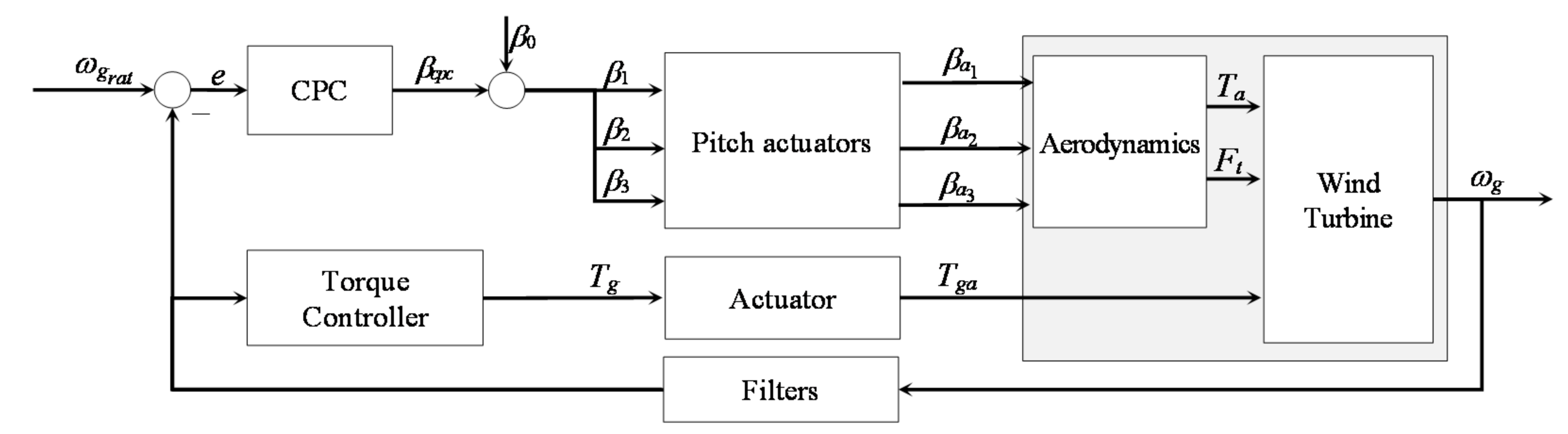
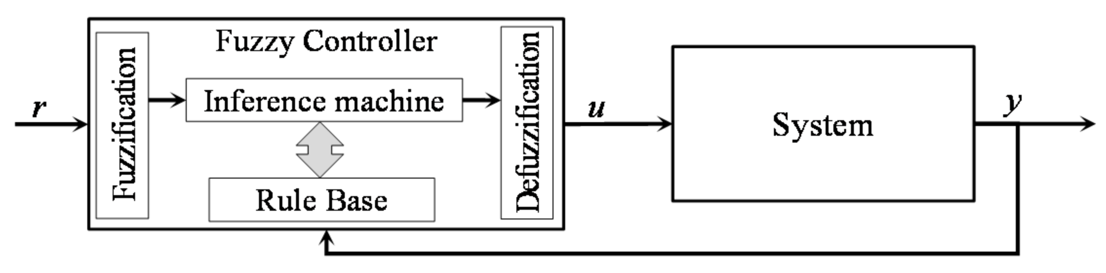
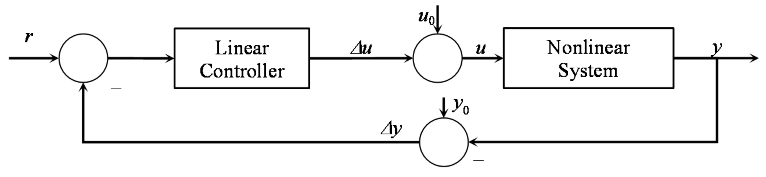


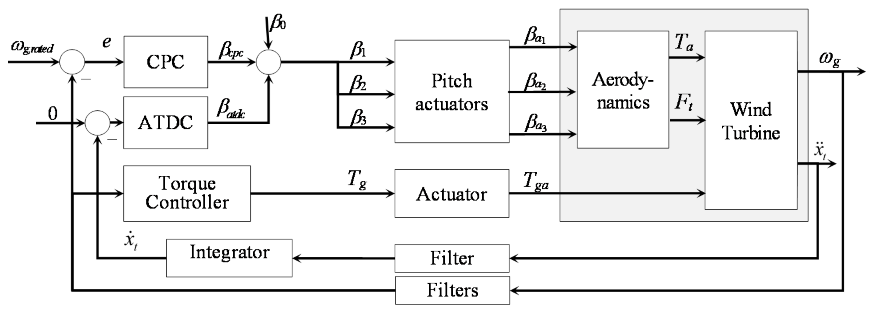


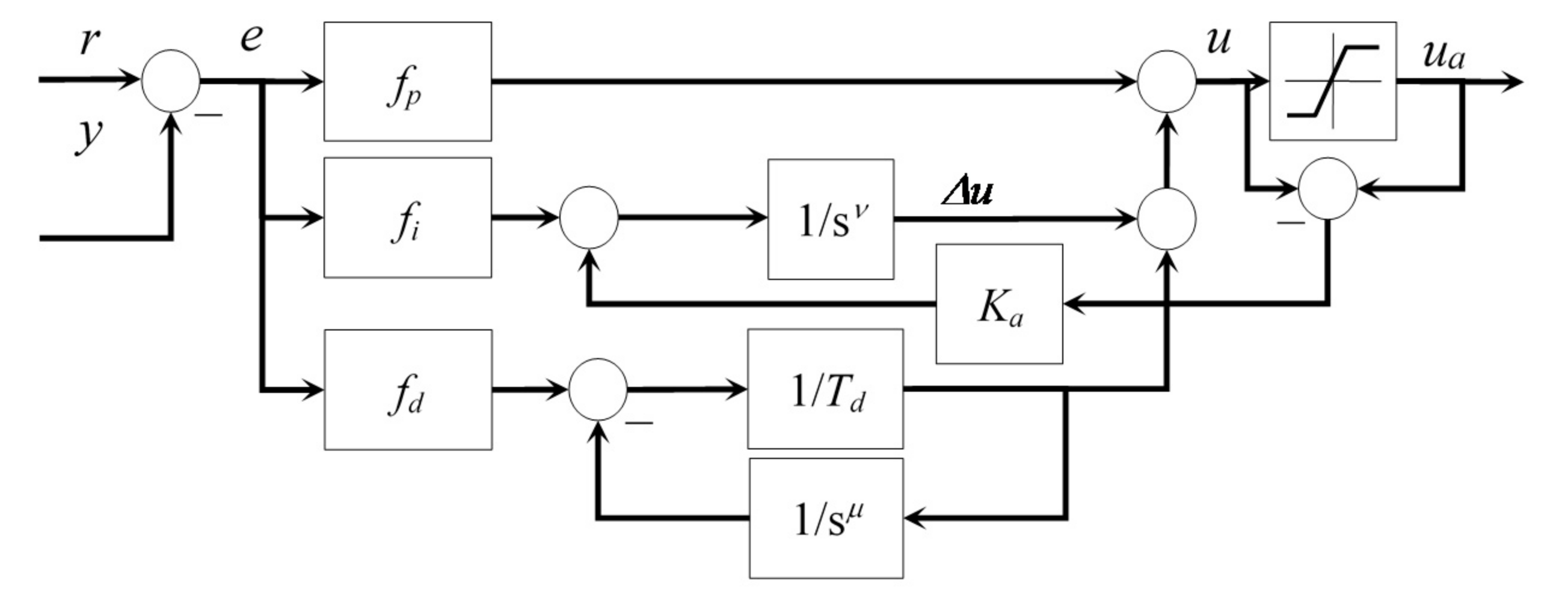
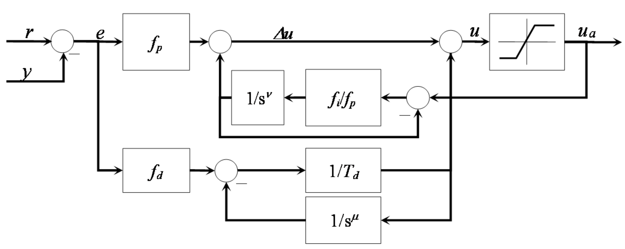

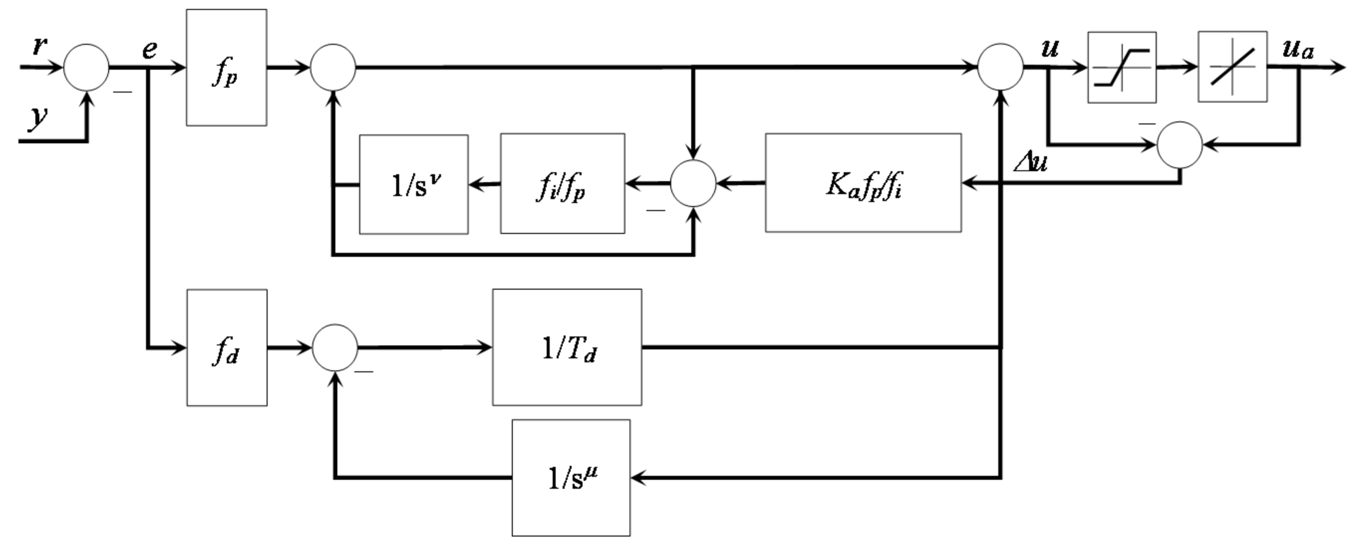
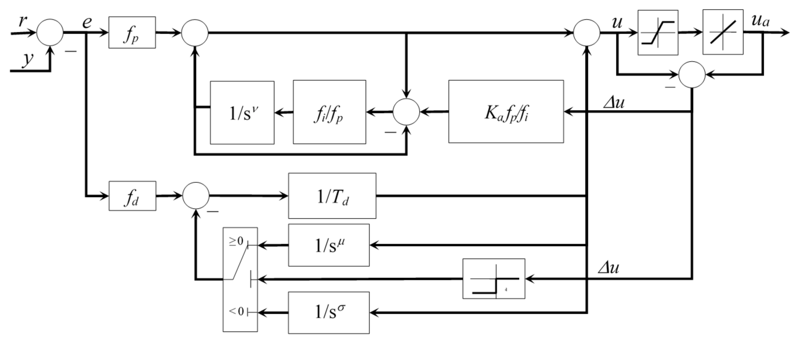
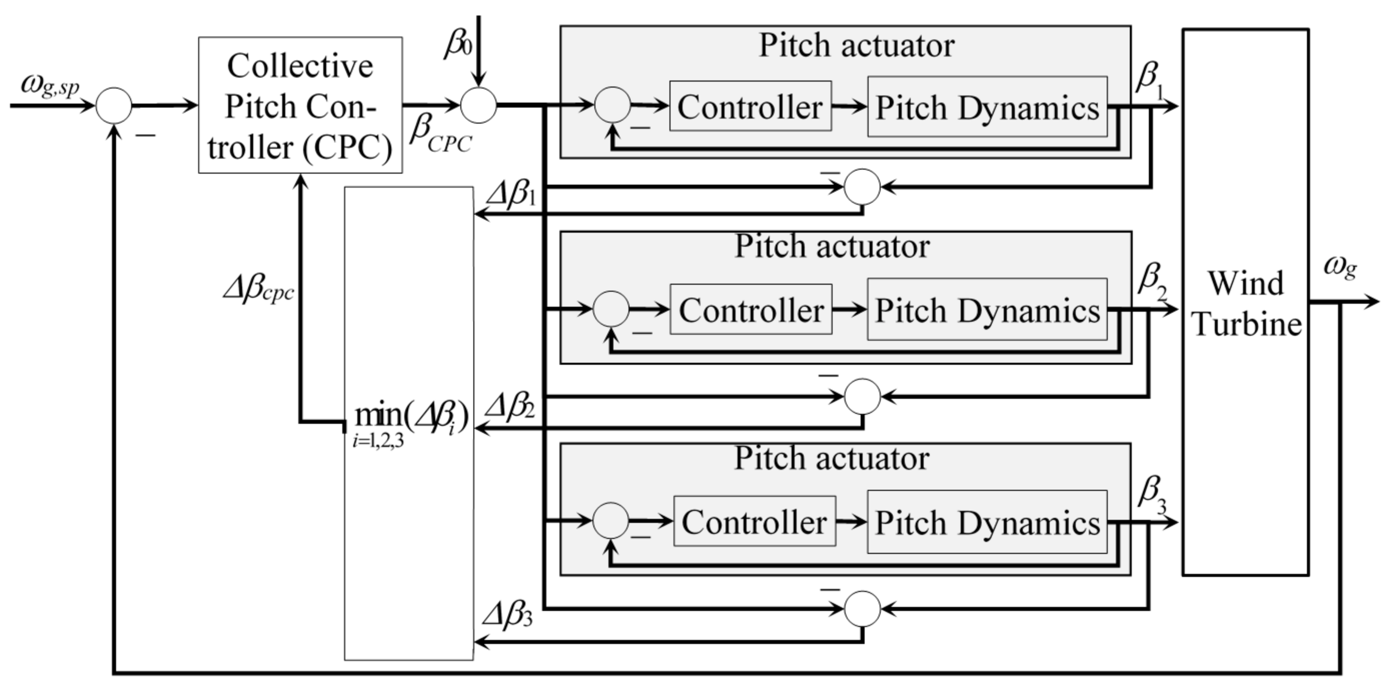

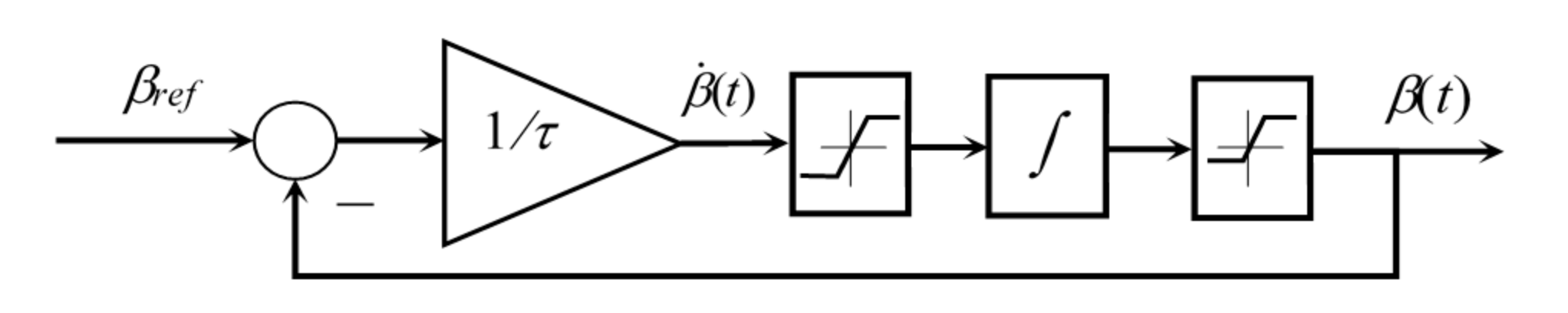

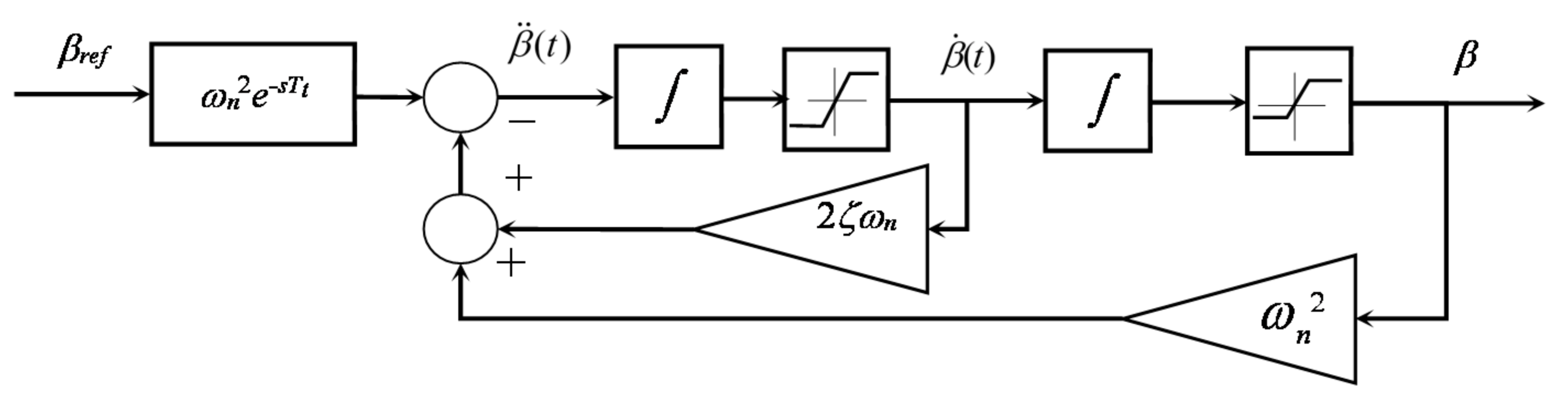


Publisher’s Note: MDPI stays neutral with regard to jurisdictional claims in published maps and institutional affiliations. |
© 2021 by the author. Licensee MDPI, Basel, Switzerland. This article is an open access article distributed under the terms and conditions of the Creative Commons Attribution (CC BY) license (https://creativecommons.org/licenses/by/4.0/).