Article

Electrohydrodynamic Enhancement of Phase Change Material Melting in Circular-Elliptical Annuli

1
School of Mathematics and Physics, China University of Geosciences, Wuhan 430074, China
2
Center for Mathematical Sciences, China University of Geosciences, Wuhan 430074, China
*
Author to whom correspondence should be addressed.
Energies 2021, 14(23), 8090; https://doi.org/10.3390/en14238090
Submission received: 16 October 2021 / Revised: 28 November 2021 / Accepted: 1 December 2021 / Published: 3 December 2021

Abstract

:
Phase change material (PCM) has received significant attention due to its great potential for thermal energy storage. However, the major undesirable property of PCM is related to its low thermal conductivity. In this work, the electrohydrodynamic (EHD) enhancement of PCM melting in circular-elliptical annuli is investigated numerically by using the lattice Boltzmann method (LBM). The key motivation for our choice of the elliptical shape is due to the fact that the more curved elliptical surface corresponds to stronger charge injection strength, which may lead to stronger flow field, and the consequent increase of heat transfer rate. The influences of several non-dimensional parameters, including electric Rayleigh number T, thermal Rayleigh number ( R a ) and the aspect ratio ( A R ) of the inner ellipse are investigated in detail. Based on the numerical results, it is found that the radial electro-convective flow induced by the external electric field makes a significant contribution to the enhancement of melting heat transfer, and specially, the maximum time saving in some cases is more than 85 % . Moreover, we observe that when the Coulomb force is dominant over the buoyancy force, no matter the inner elliptical tube is oriented horizontally or vertically, the total melting times in these two cases are nearly the same, and the melting performance obtained for the circular electrode is usually better than the other cases. However, when the flow regime is dominated by the buoyancy force, the use of a slender vertical-oriented elliptical electrode instead of the circular one is more efficient.

1. Introduction

Phase change materials (PCMs) have been well acknowledge to have prominent characteristics like heat recovery capacity, high heat storage density and repeatable utilization [1,2,3,4], and the application of PCMs is usually encountered in a widely range of scientific and engineering fields such as energy conservation in building applications [5,6], cooling of electronic devices [7], and thermal management of photovoltaic [8], just to name a few. Despite PCMs have huge potential for energy storage, the low thermal conductivity of PCMs always weakens the thermal energy charging and discharging rates [9,10], which places higher demands on heat transfer enhancement technology.
Over the last few decades, various heat transfer argumentation technologies have been implemented by researchers to improve the PCM melting performance, and the strategies include but are not limit to dispersion of highly conductive nanoparticles [11,12], use of extended surfaces [13,14] and use of high conductivity porous matrices embedded with PCM [15]. For instance, Zeng et al. [11] conducted an experimental study to investigate the melting of nanoparticle-enhanced phase change materials (NePCMs) in a bottom-heated vertical cylindrical cavity, and the authors observed that the melting rate of the NePCMs relies on the competing effect between the enhanced heat conduction and the weakened natural convection. Abdi et al. [13] experimentally investigated the effects of the vertical fins with varying number and length on the enhancement of phase change process, and it is noted that phase change processes can be improved considerably as a result of the increase of the heat transfer area by vertical fins. Shatikian et al. [14] numerically studied the efficiency of fins in a PCM heat sink during melting, and they observed that the distribution of the temperature in the fins relies on the fins thickness, and fins with lower thickness experience a larger temperature gradient in contrast to thicker ones, while approaching an isothermal condition at the end of the process, thus showing a transient behavior. In addition, the cooper foam is employed by Zhang et al. [15] to enhance the thermal conductivity of paraffin, and their experimental results show that due to the thermal non-equilibrium effect, the temperature difference between the paraffin and ligament of cooper foam is quite larger, which must be taken into consideration in the numerical simulation.
In reality, the aforementioned techniques are the so called passive heat transfer argumentation techniques, and as pointed out in some previous works [16,17], the heat transfer enhancement level of these passive techniques is usually proportional to the volume of added foreign material, and when the volume of added material increases, the thermal storage density of the system begins to decrease, which is usually undesirable in some cases, especially in thermal management of spacecraft pursuing the minimizing space [18]. Fortunately, different from the passive techniques, the active techniques do not have these limitations and they can make full use of the heat storage performance of the PCM in the system. Some examples of active heat transfer enhancement techniques include ultrasonic wave [19], magnetic field [20], mechanical vibration [21] and electrohydrodynamic (EHD) [22]. For more details on the recent progress of active heat transfer enhancement technologies for PCM melting, we refer the reader to the recent review presented by Wu et al. [23].
As one of the most promising active heat transfer enhancement techniques, electrohydrodynamic (EHD) has drawn considerable attention due to its distinct advantages such as rapid and smart control, fast responding, no moving mechanical parts [24]. Over the past few decades, extensive studies have been performed to reveal the basic mechanism of EHD enhancement of single-phase flow. For example, McCluskey et al. [25] experimentally investigated the performance of electric field in enhancing heat transfer, and the results indicate that electrical effects dominate over the buoyancy effects for all cases considered, and the average heat transfer rates are shown to increase by up to an order of magnitude when the electroconvective motion is presented. Worraker et al. [26] and Castellanos et al. [27] studied the electrohydrodynamic instability in the presence of a temperature gradient, and the results show that the flow instability is more easily to be induced when an external electric field is applied, which further give rise to the enhancement of heat transfer. More recently, Wu et al. [28] numerically studied the electro-thermo-convection induced by a strong unipolar injection between horizontal concentric annuli, and they found that the augmentation of heat transfer is due to the radial flow motion induced by unipolar injection of ions. With the similar configuration, Hassen et al. [29] numerically studied the effects of injection strength, mobility as well as radius ratio on heat transfer performance, and it is found that the heat transfer rate increases with lower values of mobility number and higher charge injection strength.
Apart from the single-phase flow system mentioned above, EHD technology has also shown some distinct advantages in enhancing two-phase heat transfer [30], such as droplet evaporation [31], boiling and condensation heat exchange [32,33]. As far as the PCM melting is considered, only few open literature can be found. To the best of our knowledge, the first experimental work on EHD enhancement of melting was conducted by Nakhla et al. [22] in 2015, and they experimentally found that the total melting time of paraffin wax can be reduced by 40.5 % under the application of the high voltage of 8.0 kV when compared to the case without electric field, and the power consumption is only 2.4 % of the heater input power. Later, Nakhla et al. [34] and Sun et al. [35] designed some other experiments to investigate the influence of the electric field on the melting of n-octadecane, and their results show that the Coulomb force plays a vital role in enhancing the melting performance. More recently, the interaction between Coulomb force and buoyancy force during melting of octadecane filled in a vertical latent heat thermal storage module is studied by Nakhla and Cotton [17], and it is observed that the application of EHD reduced the charging time by 1.7 fold as a result of EHD enhancing the convection heat transfer by cell bifurcation. In addition to the above experimental works, few numerical works on EHD melting problem are also reported. Luo et al. [36] and Selvakumar et al. [37] employed the lattice Boltzmann (LB) method and finite volume (FV) method to numerically study the EHD melting problem, respectively. Based on their numerical results, it is found that EHD can be served as a promising technique in enhancing the PCM melting, especially for the organic phase change material with a larger latent heat term.
Although these existing studies illustrate the potential of EHD in enhancing PCM melting, the configurations considered in these works are usually limited to the simple square cavity or parallel-plane [35,36,37,38]. Actually, the geometric configuration of interest in PCM melting problem is usually related to the annular cavities [39,40], and the applications of this type of containers can be found in various shell and tube heat exchangers [39]. Most recently, we note that the electro-thermo-convection with a melting boundary in horizontal concentric circular annuli is investigated by Lu et al. [41], and the authors made a detail analysis of the onset of flow motion and the dynamics of fluid flow and interface during the melting process. However, it is noted that the electrode considered in this work is a so-called circular electrode, and to our best knowledge, the investigation of EHD melting in circular-elliptical annuli has not been reported. Actually, as presented in some previous works [39,42,43], the ellipse configuration is usually encountered in industrial, and has a wide range of practical applications [39,42,43], including shell-and-tube heat exchanges, coil condensers, heat pipe design, coil distillation facilities. In addition, it is well known that for a given volume, an ellipse has a greater circumference, indicating the overall surface area of elliptical annulus is greater, which may potentially lead to better melting heat transfer performance [10,44]. Moreover, curved or sharp electrodes which leads to local high electric fields and are of great interest in EHD enhanced heat transfer [45].
Framed in this general background, in this work, we intend to study the EHD enhancement of PCM melting in circular-elliptical annuli, and as far as the numerical method is concerned, the LB method is considered which has been developed into a powerful numerical solver for modeling thermal multiphase flows with phase change [46,47,48], as well as the EHD flows [49,50,51,52]. The remainder of this paper is organized as follows. In the next section, the configuration as well as the governing equations are presented. The LB equations are introduced in Section 3. Then, two numerical validations are carried out in Section 4 and the simulation results are discussed in detail later in Section 5. Finally, some conclusions are drawn in Section 6, and some details about the numerical procedure for the present work are given in the Appendix A.

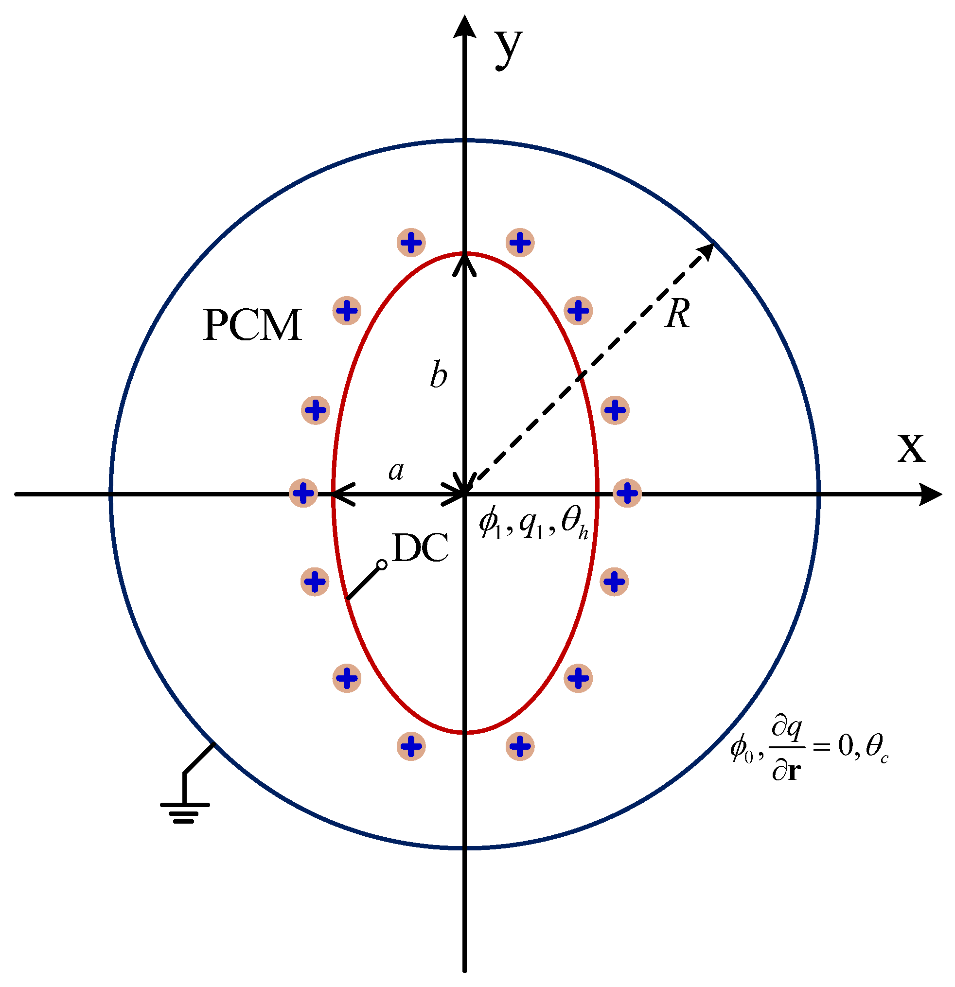
2. Physical Statement and Governing Equations

The schematic of the physical model is shown in Figure 1, in which the concentric annulus with an elliptical cylinder is initially filled with a pure dielectric substance with a melting point of θ m . The inner elliptical electrode with the semi-minor and semi-major axes being a and b (define A R = a / b as the aspect ratio) is kept at a high temperature of θ h and a high potential of ϕ 1 . In addition, the unipolar injection is considered in the present work, which means that the ions are injected from the elliptical electrode only, and the space charge q 1 at the emitter electrode is assumed to be homogeneous and autonomous. Moreover, the outer cylinder corresponds to the grounded collection electrode with a potential of ϕ 0 ( ϕ 0 < ϕ 1 ) and a temperature of θ c ( θ c = θ m < θ h ).
The fluid flow is assumed to be incompressible and Newtonian. Besides, all the thermophysical properties of PCM remain constant during the phase change process, except for the fluid density variation in the buoyancy force term, which is taken as a function of the temperature by considering the Boussinesq approximation. In such a case, the current EHD melting problem is governed by the following equations [36,46,53],
· u = 0 ,
( ρ 0 u ) t + · ( ρ 0 uu ) = p + · μ u + q E + ρ 0 g β θ θ r ,
· ε ϕ = q ,
E = ϕ ,
q t + · q K E + u = · D q ,
H t + · ( c p θ u ) = 1 ρ 0 · ( λ θ ) ,
where u = ( u x , u y ), E = ( E x , E y ) and g = ( 0 , g ) are fluid velocity field, electric field and gravitational acceleration, respectively. The scalars ρ 0 , t, p, μ , β , ϕ , q, H, θ , represent for the fluid density, time, modified pressure, dynamic viscosity, volumetric expansion coefficient, electric potential, charge density, total enthaply and temperature. In addition, the symbols ε , K, D, ( c p ) , λ are electrical permittivity, ionic mobility, charge diffusion coefficient, specific heat and thermal conductivity. Moreover, Equation (6) is the total enthalpy-based energy conservation equation, and the definition of H is given as
H = c p θ + f l L ,
where f l , L are the liquid fraction and latent heat of PCM, respectively. Obviously, the total enthalpy can be divided into two parts, the sensible heat C p θ and latent heat f l L .
To have a universal description for current problem, it is particularly convenient to work with nondimensional equations, and here the above equations are non-dimensionalized by adopting the following dimensionless quantities, identified by asterisks:
x * = x l , u * = u υ / l , t * = t l 2 / υ , q * = q q 1 , ϕ * = ϕ ϕ 1 ϕ 0 , E * = E * ϕ 1 ϕ 0 / l , θ * = θ θ h θ c , ρ * = ρ ρ 0 , p * = p ρ 0 ( υ / l ) 2 , H * = H c p ( θ h θ c ) = θ * + f l S t e ,
where the length scale is taken as l = R / 2 , and in this way, the corresponding dimensionless governing equations are expressed as [28,54]
* · u * = 0 ,
u * t * + * · ( u * u * ) = * p * + ( * ) 2 u * + T M 2 q * C E * + R a P r θ * ,
* · 1 C * ϕ * = q * ,
E * = * ϕ * ,
q * t * + * · q * T M 2 E * + u * = T M 2 α * 2 q * ,
θ * t * + * · ( θ * u * ) = 1 P r * 2 θ * + 1 S t e f l t * .
accompanied by the following seven dimensionless parameters (for clarity, asterisks are omitted) [36]:
R a = g β θ h θ c l 3 υ χ , T = ε ϕ 1 ϕ 0 μ K , C = q 1 l 2 ε ϕ 1 ϕ 0 , M = 1 K ε ρ 0 1 / 2 , P r = υ ρ c p λ , α = D K ϕ 1 ϕ 0 , S t e = c p θ h θ c L ,
in which the thermal Rayleigh number R a is defined as the ratio between the buoyancy and viscous force. Similar to R a , the electric Rayleigh number T is defined as the ratio of the Coulomb force and the viscous force. C and α is the charge injection strength and charge diffusion coefficient, respectively. In addition, the Prandtl number P r is defined as the ratio of momentum diffusion capacity to heat diffusion capacity, for the generally organic PCMs, its typical value obeys P r 10 [55]. Further, the non-dimensional mobility M is the ratio of the hydrodynamic mobility to the ionic mobility [56], and its value is always greater than 3 [57]. The Stefan number S t e indicates the ratio of sensible and latent heat of PCM. Additionally, the maximum magnitude of velocity and widely used Fourier number are adopted to measure the flow motion and melting process for phase change problem, respectively, which are defined as
V m a x = m a x ( u 2 + v 2 ) , F o = λ t ( ρ c p ) l 2 .

3. The Lattice Boltzmann Equations

3.1. Lattice Boltzmann Equation for Flow Field

In this work, the incompressible lattice Bhatnagar-Gross-Krook (LBGK) proposed by Guo et al. [53] is adopted to simulate the fluid field, and the evolution of the particle velocity distribution function reads
f i x + c i Δ t , t + Δ t f i x , t = 1 τ l f i x , t f i ( e q ) x , t + Δ t F i ,
where c i , Δ t are the discrete velocity and time step, respectively. τ l is the dimensionless relaxation time, depending on the fluid viscosity as a function of v = ρ 0 c s 2 τ l 0.5 Δ t . In addition, the f i x , t is the distribution function at time t and location x in direction i. Further, the local equilibrium distribution function f i ( e q ) x , t is defined as
f i ( e q ) ( x , t ) = η i p + ω i c i · u c s 2 + uu : ( c i c i c s 2 I ) 2 c s 4 ,
where I is the second-order identity matrix. w i and c i are weight coefficient and discrete velocity in the direction of i, which depend on the used DnQq (n-dimensional q-velocity) discrete velocity model. For all evolution functions except for the electric field, the classical D2Q9 model proposed by Qian et al. [58] is considered, and the corresponding w i and c i are given by
ω i = 4 / 9 , i = 0 , 1 / 9 , i = 1 4 , 1 / 36 , i = 5 8 ,
c i = ( 0 , 0 ) , i = 0 , c cos ( i 1 ) π 2 , sin ( i 1 ) π 2 , i = 1 4 , 2 c cos ( 2 i 1 ) π 4 , sin ( 2 i 1 ) π 4 , i = 5 8 .
where c = Δ x / Δ t is the streaming speed, and related to the sound speed through c s = c / 3 . Among them, Δ x is the lattice space. In addition, η i is the model parameter, calculated by η 0 = ω 0 1 / c s 2 + ρ 0 , η i = ω i / c s 2 ( i 0 ) . Moreover, an external force term needs to be added in Equation (18) to exert the influence of buoyancy and Coulomb force on flow motion. Based on the the modified second-order moment model proposed by Guo et al. [59], the force term can be expressed as
F i ( x , t ) = ω i 1 1 2 τ f c i · F c s 2 + Fu + uF : c i c i c s 2 I 2 c s 4 ,
where F = q E + g β l ( θ θ 0 ) . Then, the macroscopic qualities including the velocity field and pressure can be evaluated by
u = i c i f i + Δ t 2 F ,
p = c s 2 1 ω 0 i 0 f i ω 0 u 2 2 c s 2 .

3.2. Lattice Boltzmann Equation for Electric Potential

In order to accurately obtain the electric potential field, an improved LB model developed by Chai et al. [60] to solve the Poisson equation is adopted, and the corresponding evolution function reads
g i x + c i Δ t , t + Δ t g i x , t = 1 τ ϕ g i x , t g i ( e q ) x , t + Δ t ω ^ i ξ R ,
where ξ is the artificial model coefficient, controlling the evolution speed of electric potential. In addition, the source term R is defined as R = q / ε . Further, the D2Q5 discrete scheme is considered and the local equilibrium distribution function g i ( e q ) x , t reads
g i ( e q ) = ω ^ 0 1 ϕ , i = 0 , ω ^ i ϕ , i = 1 4 .
In this model, the weight coefficient ω ^ is given by
ω ^ i = 0 , i = 0 , 1 / 4 , i = 1 4 .
The relaxation time τ ϕ for potential relies on the coefficient ξ through ξ = c ^ s 2 τ ϕ 0.5 Δ t , where c ^ s 2 = c 2 / 2 . Further, the electrical potential is calculated by
ϕ = 1 1 ω ^ 0 i g i .
In addition, in order to calculate the Coulomb force, the value of electric field must be determined. The most straightforward method is to apply the difference scheme to the definition of electric field [Equation (4)]. However, due to the kinetic essence of the LB method, the electric field E can be evaluated locally by
E = 1 τ ϕ c ^ s 2 i c i g i .

3.3. Lattice Boltzmann Equation for Charge Density

The solving of charge transport equation is the pivotal part in EHD problems owing to the strong convection-dominating characteristic. Following the work of Luo et al. [49], the evolution equation for charge density is expressed as
h i x + c i Δ t , t + Δ t h i x , t = 1 τ q h i x , t h i ( e q ) x , t ,
where τ q is the dimensionless relaxation time for charge density, and it depends on the charge diffusion coefficient D e as a function of
D e = c s 2 τ q 0.5 Δ t .
Moreover, the local equilibrium distribution function h i ( e q ) x , t is defined as
h i ( e q ) ( x , t ) = q ω i { 1 + c i · K e E + u c s 2 + c i · K e E + u 2 c s 2 K e E + u 2 2 c s 4 } ,
and finally, the macroscopic charge density can be obtained by
q = i h i .

3.4. Lattice Boltzmann Equation for Temperature Field

To solve the energy conservation equation, the optimal two-relaxation-time (OTRT) LB model developed by Lu et al. [61] is employed here, which shows a great efficiency in eliminating the unphysical numerical diffusion across solid-liquid interface, and the corresponding evolution function can be expressed as
l i x + c i Δ t , t + Δ t = l i ( e q ) ( x , t ) + 1 1 2 τ s 1 2 τ a l i ( x , t ) l i ( e q ) ( x , t ) 1 2 τ s 1 2 τ a l i ( x , t ) l i ( e q ) ( x , t ) ,
where τ s and τ a denote the symmetric and anti-symmetric relaxation time. l i ¯ and l i ¯ ( e q ) represent the distribution function and equilibrium distribution function along the opposite direction of i, respectively. Among them, the local equilibrium distribution function is defined as
l i e q = H c p θ + ω i c p θ 1 | u | 2 2 c s 2 , i = 0 , ω i c p θ 1 + c i · u c s 2 + ( c i · u ) 2 2 c s 4 | u | 2 2 c s 2 , i 0 .
In this context, the anti-symmetric relaxation time is calculated by
λ ρ 0 c p = c s 2 ( τ a 0.5 ) Δ t ,
and the symmetric relaxation time can be evaluated from
1 τ s + 1 τ a = 2 .
Then, the total enthalpy can be obtained by
H = i l i .
Once H is determined, the total liquid fraction f l and temperature θ can be also calculated through the following thermodynamic relations
f l = 0 H H s H H s H l H s H s < H < H l , 1 H H l
θ = H c p H H s H l H H l H s θ s + H H s H l H s θ l H s < H < H l , θ l + H H l c p H H l
in which H s and H l are the total enthalpy at solidus temperature θ s and liquidus temperature θ l , respectively.

3.5. Boundary Treatment

In this study, the volumetric LB scheme is adopted to treat the moving phase interface boundary [62], while the non-equilibrium extrapolation scheme proposed by Guo et al. [63] is used to deal with the curved boundaries. The details for these two schemes can be found in previous works [62,63], which are not presented here for simplicity.

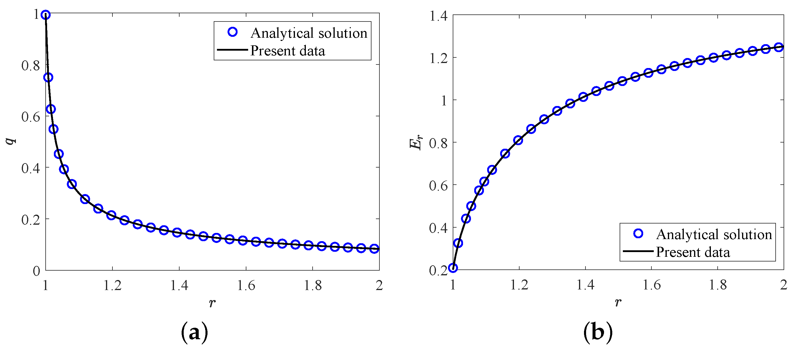
4. Code and Results Verifications

In this section, two validation tests are performed to verify the accuracy of the present LB model. Firstly, we consider the melting of PCM inside a square cavity, and the evolution of total liquid fraction and average Nusselt number along the heating wall during the melting process for S t e = 0.01 , P r = 0.02 , R a = 2.5 × 10 4 are presented in Figure 2. It can be seen that the present results agree well with the benchmark solutions reported in ref. [64]. Further, in the second test, the analytic hydrostatic solutions between two coaxial cylinders (the radius ratio is equal to 2.0 ) for C = 10 are compared with our present numerical results. The analytical solution of hydrostatic state can be found in ref. [65]. As shown in Figure 3a,b, the profiles of charge density and the electric field strength in the radial direction obtained from our numerical results show good agreements with the analytical solutions. Here we would like to point out that all the simulations in the present work are implemented on the Tesla V100S Graphics Processing Unit (GPU) using NVIDIA’s Compute Unified Device Architecture (CUDA) for a higher computing speed. Additionally, to derive the grid independence results, the grid independence test is also performed at different grid resolutions with R a = 10,000, T = 1000 , A R = 3 / 4 . As shown in Table 1, one can find that the grid resolution of 512 × 512 is fine enough to give the grid independence results, which will be adopted in the following simulations.

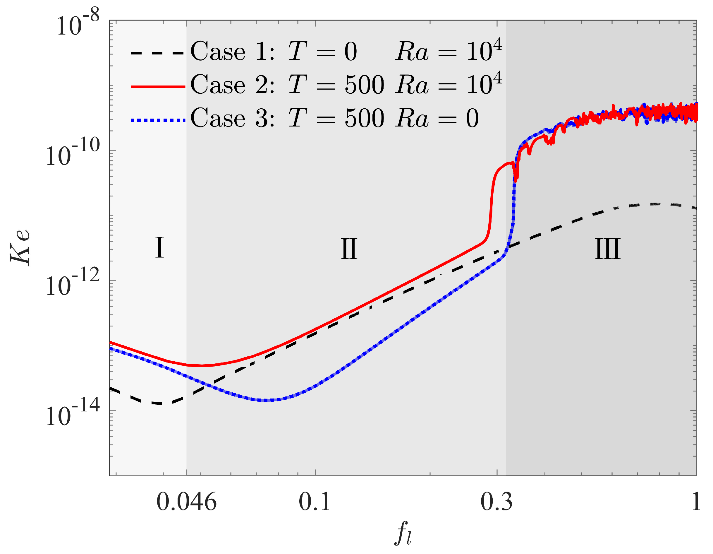
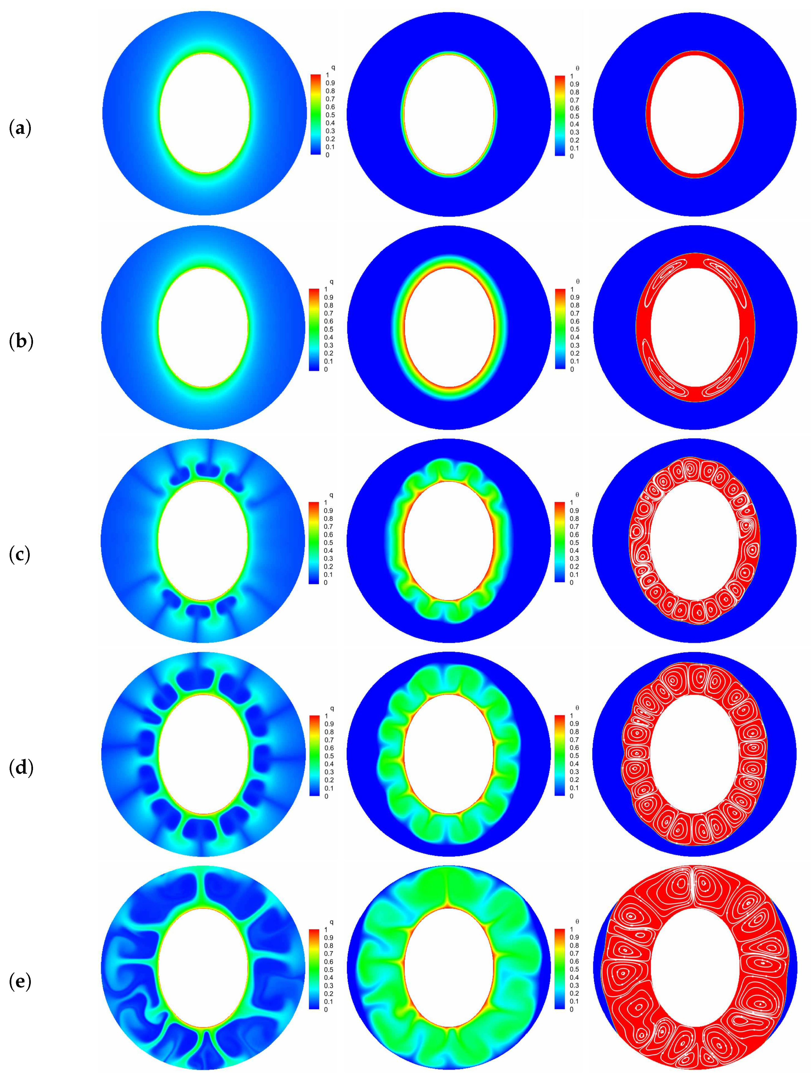
5. Results and Discussions

We now turn to investigate the effect of EHD on PCM melting in the present circular-elliptical annuli, and the distributions of charge density, temperature and flow fields during the melting process are presented and discussed. Additionally, unless specially stated, all the simulations are performed under the strong charge injection with C = 10 , and the dimensionless charge diffusion number α is set to 10 3 [41], the aspect ratio ( A R ) is kept at 3 / 4 , while the non-dimensional mobility parameter (M), Prandtl number ( P r ) and Stefan number ( S t e ) are fixed at 10, 10 and 0.1 [41], which are all in the range of typical organic dielectric PCMs in thermal energy storage applications [36]. Further, the product of the semi-major and the semi-minor axes is fixed at R 2 / 4 in this work such that the PCM volume for different configurations is a constant.
In order to have a preliminary insight into the complex physical mechanism behind EHD enhancement of PCM melting, we first focus on the onset of flow motion, which marked the transition from a purely conduction regime to a convection regime in the melting with or without electric field. As presented in the work of Lu et al. [41], the kinetic energy density ( K e ) and the effective electric Rayleigh number are usually used to capture the onset of flow motion in melting problem, which are given as
K e = 1 V f V f u 2 d V , T e = T h ¯
where V f is the volume of fluid as a function of time, u is the fluid velocity, h ¯ is the average thickness of the fluid domain, which is calculated by h ¯ = 1 R r [ r 2 + f l ( R 2 r 2 ) r ] with r = R / 2 in this work. Figure 4 plots the evolution of kinetic energy vs. the total liquid fraction for three cases, in which case 1 and case 2 represent the nature convection melting without and with electric field, respectively, and case 3 shows the EHD melting in the absence of buoyancy force effect. It can be seen that the kinetic energy density decreases gradually in all the above cases at the initial stage of melting marked by zone I, which indicates that the flow motion does not exit and heat conduction is the main mode of melting at this stage. As melting processes, the kinetic energy density in case 1 begins to increase as a result of the motivation of nature convection. This growth marks the transition to thermal convection regime marked by zone II from the initial conduction regime. Almost at the same time, the kinetic energy density for the case of melting with electric field (case 2) also increases, and it is worth noting that the growth rate for this case is similar to that for case 1 in zone II. This is the result of melting dominated by thermal convection regime since the coulomb force is too small to induce the electroconvection at present stage for case 2. As for case 3, although the convection also occurs accomplished by the increase in K e at this stage, the reason for the growth is quite different from the previous two cases. In fact, the convection for case 3 in zone II is caused by the unbalanced Coulomb force in present circular-elliptical annular system. As a result, a different growth rate of K e can be observed in Figure 4. As the melting goes on, a suddenly increase happens to K e for case 2 and case 3 at around f l = 0.32 due to the motivation of electroconvection, indicating the transition of thermal convection dominated regime to electroconvection dominated regime marked by zone III., and the corresponding critical electric Rayleigh number is about 200.0. Finally, the kinetic energy density for the cases with electric field (case 2 and case 3) are kept at large values and shakes disorderly in zone III as shown in Figure 4. Whereas, the kinetic energy density for melting without electric field (case 1) shows a decline trend at the final stage in zone III.
In what follows, the influence of the electric field on PCM melting in the absence of the buoyancy force effect (i.e., R a = 0 ) is studied. Figure 5 plots the time evolution of the liquid fraction f l as well as the maximum flow velocity V m a x , in which five representative points (marked as A , B , C , D , E ) are also included, and the corresponding distributions of charge density, temperature field and the liquid fraction with streamlines are depicted in Figure 6. At the initial stage, due to the free charges are mainly transported by the drift and diffusion mechanisms, the Coulomb force is too small to overcome the viscous damping such that heat conduction is the main mode of heat transfer at this melting stage, thus the flow motion is inhibited as discussed above and presented at point A (see Figure 6a). By passing time, as show in Figure 6b, although the distributions of the charge density and the isotherms seem uniform, four slender vortices are formed in the liquid region. Actually, since the emitter electrode in the present work is a kind of the curved electrodes, the distribution of the electric field along the surface of elliptical electrode is then related to the local curvature [45], and a sharper electrode surface usually corresponds to a higher electric field. In such a case, the Coulomb force in the present circular-elliptical annular is expected to be asymmetry, which further causes the fluid flow in the liquid region. As the melting goes on, the Coulomb force gradually increases and finally overcomes the viscous force, resulting in the sharp increase of the maximum flow velocity as shown in point C of Figure 5b. In addition, due to the electric convection is motivated at this moment, some charge void regions as well as thermal plumes can be clearly seen in the bottom and top sections of the inner elliptical tube (see Figure 6c), and along with the increasing of the flow strength, the number of them is found to increase (see Figure 6d). Further, with the increasing effect of of the radial flow, the vortices around the inner elliptic annulus formed at point C increase in size and some of them merge in paries (see Figure 6c–e). With the further development of melting (see Figure 6e), the electric convection in the annular is fully motivated and the melting rate in this stage is a little larger than that in the initial stage (Figure 5a). Moreover, as shown in point E of Figure 5b, the maximum velocity V m a x undergoes oscillation when F o 1.58 (i.e., f l = 0.62 , and the corresponding critical electric Rayleigh number is about 345.5), the EHD system transits to a chaotic state [28].
Finally, we would like to point out that due to the Coulomb force near the left and right sides of the inner elliptic electrode is smaller in contrast to the top and bottom sections, the PCM in these areas is finally melted as depicted in Figure 6e.
The above discussion clearly shows that the presence of the electric field indeed has a significant effect on PCM melting, however, it should be noted that the buoyancy force also plays an important role in PCM melting. In such a case, we are going to investigate the interaction of Coulomb and buoyancy forces for the present circular-elliptical annular, and in order to quantitatively reflect the enhancement of PCM melting, an evaluation factor Φ is introduced, which is defined as
Φ = t 0 t 1 t 0 × 100 % ,
where t 1 and t 0 stand for the total melting time for the cases with and without EHD. Figure 7 presents the time evolution of total liquid fraction f l and the charging time reduction for various electric Rayleigh number T, in which the thermal Rayleigh number is set to 10 4 , and T = 0 corresponds to the case of melting without electric field. It is clear that the total melting time is decreased with increasing the electric Rayleigh number as a result of the increasing flow strength. Specifically, we note that when the electric Rayleigh number increases from 0 to 500, the charging time of the system reduces 82.3 % (see Figure 7b), while the change in melting time caused by electric Rayleigh number varying from 500 to 1000 is just 6.4 % (see Figure 7b), which indicates that an electric Rayleigh number higher than 500 is not recommended from the perspective of energy consumption. In addition, comparing the curves in Figure 7a, one can observe that the value of the separation point obtained for a larger electric Rayleigh number is usually smaller than that obtained for a smaller one, and the PCM melting rate is enhanced with the increase of electric Rayleigh number. To intuitively illustrate this statement, the distributions of charge density, temperature field and the liquid fraction with streamlines for different electric Rayleigh numbers at F o = 2.0 are presented in Figure 8. As depicted in this figure, since the Coulomb force is increased with the increasing electric Rayleigh number, the electro-convection in the system is more easily to be induced for a larger electric Rayleigh number. As a result, it is noted that along with the increasing of the electric Rayleigh number, more electro-plumes and therm-plumes are formed around the inner elliptical electrode, which indicates that the flow strength in the annular is increased, and of course a larger PCM melting rate is expected for a larger electric Rayleigh number. Further, it is interesting to note that compared with the case of pure buoyancy force (i.e., T = 0 ), the distributions of plumes (electro- or thermo- plumes) as well as the melting front in the presence of electric field are not symmetry about the vertical centerline even at a smaller electric Rayleigh number of T = 250 . In fact, according to the works of Lu et al. [54], the influence of the buoyancy force and the Coulomb are related to the combined effect of the effective Rayleigh number and the effective electric Rayleigh number, which are the functions of the depth of the fluid layer (see Equation (16) in ref. [54]). Note that the directions of the buoyancy force and the Coulomb force are different, and when the impact of the effective Rayleigh number and the effective electric Rayleigh number are comparable, an oscillatory flow is expected, and this also explain why the flow structure in Figure 8b is asymmetrical. Finally, since the Coulomb force trends to induce a flow from inner ellipse to outer circular while buoyancy prefers a flow in the vertical direction, the thermal convection and electro-convection behave to be a cooperative mechanism in the upper region, causing the melting front expands faster in this area. However, in the lower region, owing to the opposite direction of these two forces, the melting front advances more sluggishly toward the bottom of the outer cylinder.
The aspect ratio ( A R = a / b ) appeared in the aforementioned results is fixed at a constant value of 3 / 4 , and as pointed out by some researchers [10,66] that the melting performance in the annular is also related to the the aspect ratio of the elliptical cylinder. In such a case, the influence of the aspect ratio of the inner elliptical electrode is studied in this paragraph, and all of the elliptical tubes considered here have identical area. The time evolution of the liquid fraction f l together with the total melting time for different aspect ratios A R are presented in Figure 9, in which two special thermal Rayleigh number of R a = 10 4 and R a = 10 5 are considered, and the electric Rayleigh number for all cases is set to T = 500 . As shown in Figure 9a, it can be clearly seen that as the aspect ratio increases from 1 / 2 to 2, the total melting time decreases with increasing A R up to A R = 1 at which the minimum total melting time is obtained. For A R > 1 , the total melting time starts to increase with increasing A R . According to the definition of the aspect ratio, one can also deduce from Figure 9a that for a given inner elliptical electrode, no matter the inner elliptical tube is oriented horizontally or vertically, the total melting times in these two cases are nearly the same, and the conclusion drawn here is largely different from the case of pure buoyancy force [10]. To reveal the mechanisms behind this phenomenon, the distributions of the solid-liquid interface are also presented in Figure 10. As show in this figure, although the buoyancy force is taken into account, the influence of it is insignificant in contrast to that of Coulomb force, and this statement can be verified by the comparable PCM volume in the bottom and the top sections of the annulus. In such a case, the melting performance in the circular-elliptical annular is mainly determined by the Coulomb force, which tends to induce a radial flow from the inner ellipse to the outer circular cylinder, and thus the melting performance depends little on the orientation direction of the inner elliptical electrode. In addition, since the local electric field along the surface of elliptical electrode strongly related to the local curvature, the the melting front expands faster in the areas with higher curvature (see Figure 10). Based on the present numerical results, we can concluded that as the Coulomb force is dominant over the buoyancy force, a circular electrode is recommended to enhance the PCM melting. However, as shown in Figure 9b, when the thermal Rayleigh number is increased from 10 4 to 10 5 , the total melting time is always increased with increasing A R , and in such a case, the utilization of an slender vertical-oriented elliptical electrode is recommended instead of the circular one, and this conclusion is similar to that reported for the PCM melting under the effect of pure buoyancy force [10]. Figure 11 illustrates the melting patterns for three different aspect ratios. For one thing, since the thermal convection at the top (bottom) section is cooperation (competing) with the electro-convection as already mentioned, the melting rate at the top section for all aspect ratios is slightly higher than that in the bottom section, and thus the portion of the solid PCM at the bottom of the annular is melted slowly. For another, as reported by [10,66], the intensify of the thermal convection at the top section is relatively larger for a slender vertical-oriented elliptical, and this is also the main reason why the total melting time obtained for A R = 1 / 2 is smaller compared with the other cases.

6. Conclusions

In this paper, the influence of electric field on PCM melting in circular-elliptical annuli is numerically investigated by using the lattice Boltzmann method. Different from previous works, the electrode considered here is a kind of elliptical electrode, and it is known that the more curved elliptical surface corresponds to stronger charge injection strength, which may lead to stronger flow field, and the consequent increase of heat transfer rate. In addition, for a given volume, it is known that an ellipse has a greater circumference, indicating the overall surface area of elliptical annulus is greater, which may potentially lead to better melting heat transfer performance. Four different evolution equations are employed to reveal the complex coupling among fluid field, electric field, charge density and temperature field. After verifying the present models by two tests, we firstly focus on the onset of flow motion during the melting process of PCM. Then, the influence of electric Rayleigh number, thermal Rayleigh number as well as the aspect ratio on the melting performance of PCM with electric field are studied in detail.
Based on the simulation results, it is observed that there exists three melting regimes named conduction dominated regime, thermal convection dominated regime and electroconvection dominated regime for PCM melting with electric field. In addition, results show that the melting rate can be significantly improved by applying an external electric field, and the total melting time is decreased with increasing electric Rayleigh number. Moreover, a circular electrode ( A R = 1 ) is recommended to enhance the PCM melting when the Coulomb force is dominant over the buoyancy force, while if the buoyancy force is dominant over the Coulomb force, a slender vertical-oriented elliptical electrode ( A R = 1 / 2 ) has a better performance for the enhancement of PCM melting.

Author Contributions

Methodology, formal analysis, investigation, and writing original draft preparation, K.H.; supervision, methodology, J.H.; conceptualization, supervision, review and editing, funding acquisition, L.W. All authors have read and agreed to the published version of the manuscript.

Funding

This work was financially supported by the National Natural Science Foundation of China (No. 12002320), and the Fundamental Research Funds for the Central Universities (No. CUGGC05).

Institutional Review Board Statement

Not applicable.

Informed Consent Statement

Not applicable.

Data Availability Statement

The computed data can be provided from corresponding author on request.

Conflicts of Interest

The authors declare no conflict of interest.

Appendix A. The Numerical Procedure for the Present Work

In this appendix, the solution procedure for the present work is briefly described, and the present work can be repeated with the following procedure:
(1) Initialize the values of pressure, fluid velocity, electric potential, electric field, charge density as well as the temperature field based on the physical problem, then equilibrium distribution functions f i ( e q ) , g i ( e q ) , h i ( e q ) , l i ( e q ) can be determined from Equations (18), (25), (31) and (34), which are also used to initialize the distribution function f i , g i , h i , l i .
(2) Perform the collision and the streaming steps of Equation (17), and calculate the pressure p and the fluid velocity u by using Equations (22) and (23).
(3) Solve the lattice Boltzmann equation for electric potential [i.e., Equation (24)], and calculate the electric potential ϕ and the electric field E by employing Equations (27) and (28), respectively.
(4) Perform the collision and the streaming steps of Equation (29), and calculate the charge density q with Equation (32).
(5) Solve the lattice Boltzmann equation for temperature field [i.e., Equation (33)], and calculate the total liquid fraction f l and temperature θ using Equations (38) and (39), respectively.
(6) Go back to step 2 with updated body force until the melting process is finished.

References

  1. Zalba, B.; Marın, J.M.; Cabeza, L.F.; Mehling, H. Review on thermal energy storage with phase change: Materials, heat transfer analysis and applications. Appl. Therm. Eng. 2003, 23, 251–283. [Google Scholar] [CrossRef]
  2. Kenisarin, M.; Mahkamov, K. Solar energy storage using phase change materials. Renew. Sustain. Energy Rev. 2007, 11, 1913–1965. [Google Scholar] [CrossRef]
  3. Sharma, A.; Tyagi, V.V.; Chen, C.; Buddhi, D. Review on thermal energy storage with phase change materials and applications. Renew. Sustain. Energy Rev. 2009, 13, 318–345. [Google Scholar] [CrossRef]
  4. Tomita, S.; Celik, H.; Mobedi, M. Thermal analysis of solid/liquid phase change in a cavity with one wall at periodic temperature. Energies 2021, 14, 5957. [Google Scholar] [CrossRef]
  5. Khudhair, A.M.; Farid, M.M. A review on energy conservation in building applications with thermal storage by latent heat using phase change materials. Energy Convers. Manag. 2004, 45, 263–275. [Google Scholar] [CrossRef]
  6. Sheikholeslami, M.; Jafaryar, M.; Shafee, A.; Babazadeh, H. Acceleration of discharge process of clean energy storage unit with insertion of porous foam considering nanoparticle enhanced paraffin. J. Clean. Prod. 2020, 261, 121206. [Google Scholar] [CrossRef]
  7. Kalbasi, R.; Salimpour, M.R. Constructal design of phase change material enclosures used for cooling electronic devices. Appl. Therm. Eng. 2015, 87, 339–349. [Google Scholar] [CrossRef]
  8. Atkin, P.; Farid, M.M. Improving the efficiency of photovoltaic cells using PCM infused graphite and aluminum fins. Sol. Energy 2015, 114, 217–228. [Google Scholar] [CrossRef]
  9. Mat, S.; Al-Abidi, A.A.; Sopian, K.; Sulaiman, M.Y.; Mohammad, A.T. Enhance heat transfer for PCM melting in triplex tube with internal-external fins. Energy Convers. Manag. 2013, 74, 223–236. [Google Scholar] [CrossRef]
  10. Darzi, A.A.R.; Jourabian, M.; Farhadi, M. Melting and solidification of PCM enhanced by radial conductive fins and nanoparticles in cylindrical annulus. Energy Convers. Manag. 2016, 118, 253–263. [Google Scholar] [CrossRef]
  11. Zeng, Y.; Fan, L.; Xiao, Y. An experimental investigation of melting of nanoparticle-enhanced phase change materials (NePCMs) in a bottom-heated vertical cylindrical cavity. Int. J. Heat Mass Transf. 2013, 66, 111–117. [Google Scholar] [CrossRef]
  12. Khodadadi, M.; Sheikholeslami, M. Heat transfer efficiency and electrical performance evaluation of photovoltaic unit under influence of NEPCM. Int. J. Heat Mass Transf. 2021, 122232. [Google Scholar] [CrossRef]
  13. Abdi, A.; Shahrooz, M.; Chiu, J.N.W. Experimental investigation of solidification and melting in a vertically finned cavity. Appl. Therm. Eng. 2021, 198, 117459. [Google Scholar] [CrossRef]
  14. Shatikian, V.; Ziskind, G.; Letan, R. Numerical investigation of a PCM-based heat sink with internal fins. Int. J. Heat Mass Transf. 2005, 48, 3689–3706. [Google Scholar] [CrossRef]
  15. Zhang, P.; Meng, Z.; Zhu, H. Experimental and numerical study of heat transfer characteristics of a paraffin/metal foam composite PCM. Energy Procedia 2015, 75, 3091–3097. [Google Scholar] [CrossRef] [Green Version]
  16. Velraj, R.; Seeniraj, R.V.; Hafner, B.; Faber, C.; Schwarzer, K. Heat transfer enhancement in a latent heat storage system. Sol. Energy 1999, 65, 171–180. [Google Scholar] [CrossRef]
  17. Nakhla, D.; Cotton, J.S. Effect of electrohydrodynamic (EHD) forces on charging of a vertical latent heat thermal storage module filled with octadecane. Int. J. Heat Mass Transf. 2021, 167, 120828. [Google Scholar] [CrossRef]
  18. Wu, W.; Liu, N.; Cheng, W.; Liu, Y. Study on the effect of shape-stabilized phase change materials on spacecraft thermal control in extreme thermal environment. Energy Convers. Manag. 2013, 69, 174–180. [Google Scholar] [CrossRef]
  19. Setareh, M.; Saffar-Avval, M.; Abdullah, A. Experimental and numerical study on heat transfer enhancement using ultrasonic vibration in a double-pipe heat exchanger. Appl. Therm. Eng. 2019, 159, 113867. [Google Scholar] [CrossRef]
  20. Shi, E.; Zonouzi, S.A.; Aminfar, H.; Mohammadpourfard, M. Enhancement of the performance of a NEPCM filled shell-and-multi tube thermal energy storage system using magnetic field: A numerical study. Appl. Therm. Eng. 2020, 178, 115604. [Google Scholar] [CrossRef]
  21. Al Omari, S.A.B.; Ghazal, A.M.; Elnajjar, E.; Qureshi, Z.A. Vibration-enhanced direct contact heat exchange using gallium as a solid phase change material. Int. Commun. Heat Mass Transf. 2021, 120, 104990. [Google Scholar] [CrossRef]
  22. Nakhla, D.; Sadek, H.; Cotton, J.S. Melting performance enhancement in latent heat storage module using solid extraction electrohydrodynamics (EHD). Int. J. Heat Mass Transf. 2015, 81, 695–704. [Google Scholar] [CrossRef]
  23. Wu, Y.; Zhang, X.; Xu, X.; Lin, X.; Liu, L. A review on the effect of external fields on solidification, melting and heat transfer enhancement of phase change materials. J. Energy Storage 2020, 31, 101567. [Google Scholar] [CrossRef]
  24. Seyed-Yagoobi, J.; Bryan, J.E. Enhancement of heat transfer and mass transport in single-phase and two-phase flows with electrohydrodynamics. Adv. Heat Transf. 1999, 33, 95–186. [Google Scholar]
  25. McCluskey, F.M.J.; Atten, P.; Perez, A.T. Heat transfer enhancement by electroconvection resulting from an injected space charge between parallel plates. Int. J. Heat Mass Transf. 1991, 34, 2237–2250. [Google Scholar] [CrossRef]
  26. Worraker, W.J.; Richardson, A.T. The effect of temperature-induced variations in charge carrier mobility on a stationary electrohydrodynamic instability. J. Fluid Mech. 1979, 93, 29–45. [Google Scholar] [CrossRef]
  27. Castellanos, A.; Velarde, M.G. Electrohydrodynamic stability in the presence of a thermal gradient. Phys. Fluids 1981, 24, 1784. [Google Scholar] [CrossRef]
  28. Wu, J.; Traoré, P.; Zhang, M.; Pérez, A.T.; Vázquez, P.A. Charge injection enhanced natural convection heat transfer in horizontal concentric annuli filled with a dielectric liquid. Int. J. Heat Mass Transf. 2016, 92, 139–148. [Google Scholar] [CrossRef]
  29. Hassen, W.; Oztop, H.F.; Kolsi, L.; Borjini, M.N.; Abu-Hamdeh, N. Analysis of the electro-thermo-convection induced by a strong unipolar injection between two concentric or eccentric cylinders. Numer. Heat Tranf. A Appl. 2017, 71, 789–804. [Google Scholar] [CrossRef]
  30. Rashidi, S.H.; Bafekr, R.; Masoodi, R.; Languri, E.M. EHD in thermal energy systems—A review of the applications, modelling, and experiments. J. Electrostat. 2017, 90, 1–14. [Google Scholar] [CrossRef]
  31. Heidarinejad, G.; Babaei, R. Numerical investigation of electrohydrodynamics (EHD) enhanced water evaporation using Large Eddy Simulation turbulent model. J. Electrostat. 2015, 77, 76–87. [Google Scholar] [CrossRef]
  32. Gao, M.; Cheng, P.; Quan, X. An experimental investigation on effects of an electric field on bubble growth on a small heater in pool boiling. Int. J. Heat Mass Transf. 2013, 67, 987–991. [Google Scholar] [CrossRef]
  33. Sadek, H.; Ching, C.Y.; Cotton, J. The effect of pulsed electric fields on horizontal tube side convective condensation. Int. J. Heat Mass Transfer. 2010, 53, 3721–3732. [Google Scholar] [CrossRef]
  34. Nakhla, D.; Thompson, E.; Lacroix, B.; Cotton, J.S. Measurement of heat transfer enhancement in melting of n-Octadecane under gravitational and electrohydrodynamics (EHD) forces. J. Electrostat. 2018, 92, 31–37. [Google Scholar] [CrossRef]
  35. Sun, Z.; Yang, P.; Luo, K.; Wu, J. Experimental investigation on the melting characteristics of n-octadecane with electric field inside macrocapsule. Int. J. Heat Mass Transfer. 2021, 173, 121238. [Google Scholar] [CrossRef]
  36. Luo, K.; Pérez, A.T.; Wu, J.; Yi, H.; Tan, H. Efficient lattice Boltzmann method for electrohydrodynamic solid-liquid phase change. Phys. Rev. E 2019, 100, 013306. [Google Scholar] [CrossRef] [PubMed]
  37. Selvakumar, R.D.; Qiang, L.; Luo, K.; Traoré, P.; Wu, J. Numerical modeling of solid-liquid phase change under the influence an external electric field. Int. J. Multiph. Flow 2021, 136, 103550. [Google Scholar] [CrossRef]
  38. He, K.; Guo, X.; Zhang, X.; Wang, L. Numerical investigation of electrohydrodynamic solid-liquid phase change in square enclosure. Acta Phys. Sin. 2021, 70, 149101. [Google Scholar]
  39. Dhaidan, N.S.; Khodadadi, J.M. Melting and convection of phase change materials in different shape containers: A review. Renew. Sustain. Energy Rev. 2015, 43, 449–477. [Google Scholar] [CrossRef] [Green Version]
  40. Hassen, W.; Elkhazen, M.I.; Traore, P.; Borjini, M.N. Charge injection in horizontal eccentric annuli filled with a dielectric liquid. Eur. J. Mech. B/Fluids 2018, 72, 691–700. [Google Scholar] [CrossRef]
  41. Lu, C.; Luo, K.; Zhou, P.; Yi, H. Lattice Boltzmann analysis for electro-thermo-convection with a melting boundary in horizontal concentric annuli. Phys. Fluids 2021, 33, 043605. [Google Scholar] [CrossRef]
  42. Schulenberg, F.J. Finned elliptical tubes and their application in air-cooled heat exchangers. ASME J. Eng. Ind. 1966, 88, 176–186. [Google Scholar] [CrossRef]
  43. Chang, T.; Yeh, W. Theoretical investigation into condensation heat transfer on horizontal elliptical tube in stationary saturated vapor with wall suction. Appl. Therm. Eng. 2011, 31, 946–953. [Google Scholar] [CrossRef]
  44. Wang, X.; Djakovic, U.; Bao, H. Experimental evaluation of heat transfer performance under natural and forced convection around a phase change material encapsulated in various shapes. Sustain. Energy Technol. Assess. 2021, 44, 101025. [Google Scholar] [CrossRef]
  45. Léal, L.; Miscevic, M.; Lavieille, P.; Amokrane, M.; Pigache, F.; Topin, F.; Nogarède, B.; Tadrist, L. An overview of heat transfer enhancement methods and new perspectives: Focus on active methods using electroactive materials. Int. J. Heat Mass Transf. 2013, 61, 505–524. [Google Scholar] [CrossRef]
  46. Huang, R.; Wu, H.; Cheng, P. A new lattice Boltzmann model for solid-liquid phase change. Int. J. Heat Mass Transf. 2013, 59, 295–301. [Google Scholar] [CrossRef]
  47. Li, Q.; Luo, K.; Kang, Q.; He, Y.; Chen, Q.; Liu, Q. Lattice boltzmann methods for multi-phase flow and phase-change heat transfer. Prog. Energy Combust. Sci. 2016, 52, 62–105. [Google Scholar] [CrossRef] [Green Version]
  48. Huang, J.; He, K.; Wang, L. Pore-Scale Investigation on Natural Convection Melting in a Square Cavity with Gradient Porous Media. Energies 2021, 14, 4274. [Google Scholar] [CrossRef]
  49. Luo, K.; Wu, J.; Yi, H.; Tan, H. Lattice Boltzmann model for Coulomb-driven flows in dielectric liquids. Phys. Rev. E 2016, 93, 023309. [Google Scholar] [CrossRef] [PubMed]
  50. Luo, K.; Wu, J.; Yi, H.; Tan, H. Lattice Boltzmann modelling of electro-thermo-convection in a planar layer of dielectric liquid subjected to unipolar injection and thermal gradient. Int. J. Heat Mass Transf. 2016, 103, 832–846. [Google Scholar] [CrossRef]
  51. He, K.; Chai, Z.; Wang, L.; Ma, B.; Shi, B. Numerical investigation of electro-thermo-convection with a solid-liquid interface via the lattice Boltzmann method. Phys. Fluids 2021, 33, 037128. [Google Scholar] [CrossRef]
  52. Wang, L.; Wei, Z.; Li, T.; Chai, Z.; Shi, B. A lattice Boltzmann modelling of electrohydrodynamic conduction phenomenon in dielectric liquids. Appl. Math. Model. 2021, 95, 361–378. [Google Scholar] [CrossRef]
  53. Guo, Z.; Shi, B.; Wang, N. Lattice BGK model for incompressible Navier–Stokes equation. J. Comput. Phys. 2000, 165, 288–306. [Google Scholar] [CrossRef]
  54. Lu, C.L.; Luo, K.; Zhou, P.C.; Yi, H.L. Rayleigh-Bénard convection in a dielectric fluid under an external electric field with a melting boundary. Phys. Rev. Fluids 2021, 6, 063504. [Google Scholar] [CrossRef]
  55. Kenisarin, M.M. Thermophysical properties of some organic phase change materials for latent heat storage. A review. Sol. Energy 2014, 107, 553–575. [Google Scholar] [CrossRef]
  56. Felici, N. Phénomènes hydro et aérodynamiques dans la conduction des diélectriques fluides. Rev. Gen. Electr. 1969, 78, 717–734. [Google Scholar]
  57. Atten, P. Electrohydrodynamic instability and motion induced by injected space charge in insulating liquids. IEEE Trans. Dielectr. Electr. Insul. 1996, 3, 1–17. [Google Scholar] [CrossRef]
  58. Qian, Y.; d’Humiéres, D.; Lallemand, P. Lattice BGK models for Navier-Stokes equation. Europhys. Lett. 1992, 17, 479. [Google Scholar] [CrossRef]
  59. Guo, Z.; Zheng, C.; Shi, B. Discrete lattice effects on the forcing term in the lattice Boltzmann method. Phys. Rev. E 2002, 65, 046308. [Google Scholar] [CrossRef] [PubMed]
  60. Chai, Z.; Shi, B. A novel lattice Boltzmann model for the Poisson equation. Appl. Math. Model. 2008, 32, 2050–2058. [Google Scholar] [CrossRef]
  61. Lu, J.; Lei, H.; Dai, C. An optimal two-relaxation-time lattice Boltzmann equation for solid-liquid phase change: The elimination of unphysical numerical diffusion. Int. J. Therm. Sci. 2019, 135, 17–29. [Google Scholar] [CrossRef]
  62. Huang, R.; Wu, H. Total enthalpy-based lattice Boltzmann method with adaptive mesh refinement for solid-liquid phase change. J. Comput. Phys. 2016, 315, 65–83. [Google Scholar] [CrossRef]
  63. Guo, Z.; Zheng, C.; Shi, B. An extrapolation method for boundary conditions in lattice Boltzmann method. Phys. Fluids 2002, 14, 2007–2010. [Google Scholar] [CrossRef]
  64. Mencinger, J. Numerical simulation of melting in two-dimensional cavity using adaptive grid. J. Comput. Phys. 2004, 198, 243–264. [Google Scholar] [CrossRef]
  65. Wu, J.; Vázquez, P.A.; Traoré, P.; Pérez, A.T. Finite amplitude electroconvection induced by strong unipolar injection between two coaxial cylinders. Phys. Fluids 2014, 26, 124105. [Google Scholar] [CrossRef]
  66. Bazai, H.; Moghimi, M.A.; Mohammed, H.I. Numerical study of circular-elliptical double-pipe thermal energy storage systems. J. Energy Storage 2020, 30, 101440. [Google Scholar] [CrossRef]
Figure 1. Schematic of EHD melting in a circular-elliptical annular.
Energies 14 08090 g001
Figure 2. The comparisons of (a) total liquid fraction and (b) average Nusselt number with F o between present numerical results and Mencinger’s [64] results. Parameters: R a = 2.5 × 10 4 , P r = 0.02 , S t e = 0.01 .
Energies 14 08090 g002
Figure 3. The comparisons of (a) charge density and (b) electric field strength at hydrostatic state between present numerical results and analytical solutions.
Energies 14 08090 g003
Figure 4. Kinetic energy density K e in the fluid domain vs. total liquid fraction f l in which A R = 3 / 4 .
Energies 14 08090 g004
Figure 5. Time evolution of (a) the total liquid fraction f l and (b) the maximum flow velocity V m a x . Parameters: R a = 0 , T = 500 , A R = 3 / 4 .
Energies 14 08090 g005
Figure 6. The transient distributions of charge density, temperature field and the liquid fraction with streamlines at five representative instants [(a) point A , F o = 0.045 ; (b) pont B , F o = 0.498 ; (c) point C , F o = 1.019 ; (d) point D , F o = 1.381 ; (e) point E , F o = 2.491 ]. Parameters: R a = 0 , T = 500 , A R = 3 / 4 .
Energies 14 08090 g006
Figure 7. (a) Time evolution of the total liquid fraction f l , and (b) the the charging time reduction for different electric Rayleigh number. Parameters: R a = 10,000, A R = 3 / 4 .
Energies 14 08090 g007
Figure 8. The transient distributions of charge density, temperature field and the liquid fraction with streamlines at F o = 2.0 for different electric Rayleigh numbers ((a) T = 0 ; (b) T = 250 ; (c) T = 350 ; (d) T = 500 ). Parameters: R a = 10,000, A R = 3 / 4 .
Energies 14 08090 g008
Figure 9. Time evolution of the total liquid fraction f l for different aspect ratios A R in which T = 500 : (a) R a = 10 4 ; (b) R a = 10 5 .
Energies 14 08090 g009
Figure 10. The transient distributions of the solid-liquid interface for different aspect ratios ((a) A R = 1 / 2 ; (b) A R = 1 ; (c) A R = 2 ) at F o = 1.0 , 2.0 and 2.7 , in which R a = 10 4 , T = 500 .
Energies 14 08090 g010
Figure 11. The transient distributions of the solid-liquid interface for different aspect ratios ((a) A R = 1 / 2 ; (b) A R = 1 ; (c) A R = 2 ) at F o = 1.0 , 5.4 and 8.2 , in which R a = 10 5 , T = 500 .
Energies 14 08090 g011
Table 1. The total melting time and averaged maximum velocity at different grid resolutions. Parameters: R a = 10,000, T = 1000 , A R = 3 / 4 .
Grid Resolution 312 × 312 512 × 512 704 × 704
Total melting time2.04071.99701.9894
Averaged maximum velocity104.485197.785896.3265
Publisher’s Note: MDPI stays neutral with regard to jurisdictional claims in published maps and institutional affiliations.

