Abstract
In this study, we have proposed a novel current injection determination method that improves the voltage unbalance based on the unbalanced line impedance in a distribution network with a large-capacity PV system. An increase in the unbalance of the distribution line voltage was observed owing to a large-scale reverse power flow. To visualize this phenomenon, the P-V curves were derived for each phase to indicate the increase in the voltage unbalance with respect to the reverse power flow. Based on the derived P-V curves, the effect of a current unbalance on the voltage unbalance was investigated. It was clarified that there is a current unbalance that can improve the voltage unbalance even if the line impedance is unbalanced. In other words, the current unbalance that can theoretically make the voltage unbalance zero could be expressed in terms of the symmetrical components of unbalanced line impedance. As an application of the proposed method, the effect of the mitigation of voltage unbalance was demonstrated by controlling single-phase reactors, whose numbers were determined by using the relationship between the unbalanced line current and unbalanced line impedance.
1. Introduction
When the amount of photovoltaic (PV) power generation interconnection to the distribution system increases, it affects the power quality by increasing the distribution line voltage owing to the reverse power flow [1]. Therefore, it is necessary to take measures against the voltage increase associated with the PV interconnection in addition to the equipment planning based on the conventional demand assumption. To maintain the voltage within the proper range at a limited cost, it is necessary to understand the characteristics of equipment related to voltage control, such as the distribution lines and voltage regulation equipment, and functionally combine them for operation.
In contrast, in recent years, a rare phenomenon in conventional distribution systems has been observed due to the significant increase in the number of PV interconnections. The distribution line voltage generally increased during the reverse power flow; however, a reduction in the distribution line voltage and an expansion of voltage unbalance were observed during the large-scale reverse power flow [2]. The distribution line voltage reduction owing to the reverse power flow could be explained by an increase in the voltage with respect to the active power as it affects the line resistance and a decrease in the voltage with respect to the reactive power as it affects the line reactance [2,3,4]. The voltage unbalance in the distribution network is usually explained in terms of an unbalanced load, an unbalanced PV system, and unbalanced distribution system impedance [5]. It is clear from the observation results in the actual distribution line that the expansion of the voltage unbalance is also affected by the voltage reduction; however, no theoretical explanation has been provided.
Voltage unbalance in power systems, which has a significant impact on customer equipment, such as increased electromagnetic losses in induction motors [6] and emission of harmonic currents from inverters [7], is widely known as one of the issues of power quality. Therefore, various studies on the analysis of voltage unbalance have previously been conducted. A new sparse formulation for analyzing unbalanced voltage is shown to be robust and can be solved with a small number of convergence times [8]. A three-phase power flow solution method that contributes to real-time control in distribution automation systems is described [9]. A method to analyze the voltage unbalance in distribution systems with renewable energy sources has been proposed based on a sequence networks-based methodology [10]. In [11], a method to clarify the voltage unbalance in a distribution system with plug-in electric vehicles based on a Monte Carlo stochastic analysis is proposed. Although the voltage deviation is the main factor determining the hosting capacity of PV [12,13,14], voltage unbalance can also be one of the limiting factors for hosting capacity [15]. In another study [16], a stochastic method suggests that the high PV penetration may cause a voltage unbalance problem. Although the analytical results of these studies indicate that an increase in PV penetration affect the expansion of voltage unbalance, few studies have analyzed the cause of the expansion of voltage unbalance with an increase in PV penetration from the perspective of line impedance unbalance.
The primary purpose of this study is to analytically indicate the expansion of voltage unbalance caused by the voltage reduction and impedance unbalance of the distribution line. The expansion phenomenon of the voltage unbalance measured in the actual distribution system has been introduced in Section II. The P-V curve for each phase was derived from the circuit equation, and the expansion of voltage unbalance caused by the increase in the reverse power flow has been visualized in Section III.
The second purpose of this study is to develop the mitigation of voltage unbalance in the distribution system. There have been various investigations on voltage unbalance management. Table 1 summarizes the results of the survey on voltage unbalance mitigations. Because most of the voltage unbalance in the distribution system depends on the magnitude of the single-phase load, the reconfiguration of the distribution system is useful for improving the voltage unbalance [17]. In a similar study, a method to minimize the voltage unbalance by switching the residential load from one phase to another phase has been proposed [18]. Controlling the supply current to the three-phase rectifier is useful for mitigating the voltage unbalance [19]. For example, in [20] a metaheuristic method was proposed to solve the optimum capacitor placement problem for the purpose of improving the distribution system loss, and voltage unbalance. An application of the optimal power flow problem to determine the active power curtailment and reactive power control amount of a single-phase inverter was proposed to improve the voltage unbalance [21]. The three-phase inverter structure with the control algorithm, which injects asymmetrical power to reduce the voltage unbalance, has been proposed [22]. In another study [23], an injection current that behaves as a resistor against the negative and zero phase voltages was proposed with a battery storage system. A control method for a single-phase battery storage system was developed, and a demonstration test was conducted to improve the voltage unbalance of the low-voltage system to which the PV was connected [24]. Although three single-phase inverters can be combined and used to supply power as a three-phase inverter [25], it has been proposed to improve the voltage unbalance by controlling the combined inverter with an active power filtering function [26]. Coordinated control of electric vehicle chargers and PV inverters was proposed to eliminate the power imbalance that differed from phase to phase [27]. The smart inverter for a PV could mitigate the voltage unbalance by controlling the active and reactive powers based on particle swarm optimization [28]. Through computer simulations and experiments, it was confirmed that injecting an asymmetric three-phase current with STATCOM effectively improved the voltage unbalance [29]. A proposed control algorithm for distribution static compensators and dynamic voltage restorers to improve the voltage unbalance in low-voltage distribution system has been verified by using electromagnetic transient programs [30]. A control method of a three-phase inverter is proposed to improve the voltage unbalance of the islanded microgrid. Although the compensation value of improving the voltage unbalance is designed according to the impedance of the system, the unbalance of the distribution line impedance is not taken into account [31].

Table 1.
Summary of survey on voltage unbalance mitigations.
The improvement measures of voltage unbalance adopted in several papers generally detected the voltage unbalance and injected the unbalanced current by controlling the equipment such as the load, inverter, and reactive power compensation system for reducing the voltage unbalance. The method proposed in this study is novel in such a way that the injected unbalanced current is determined based on the unbalanced line impedance. To our knowledge, there are no papers that discuss the improvement of voltage unbalance by this method. The expansion phenomenon of voltage unbalance caused by the voltage reduction owing to the reverse power flow strongly depends on the unbalanced line impedance. Therefore, by focusing on the unbalanced line impedance, we have developed a method for injecting an unbalanced current.
The remainder of this paper is organized as follows: The proposed improvement of voltage unbalance based on the unbalanced line impedance is presented in Section IV, with application case studies provided in Section V, followed by the conclusions in Section VI.
2. Measurement of Expansion of Voltage Unbalance
From the measurement of the medium-voltage distribution feeder, it was found that the unbalanced voltage expanded owing to the reverse power flow from the large-capacity PV system. Figure 1 depicts an actual medium-voltage feeder in Japan, in which the expansion of unbalanced voltage was measured. A large-capacity PV system of 7000 kW was interconnected 7.05 km away from the substation. Medium-voltage and low-voltage customers were distributed via the distribution line. The sum of the maximum power consumption of each customer is described between the nodes in Figure 1. The voltage and current near the substation and PV system were measured using sensors.
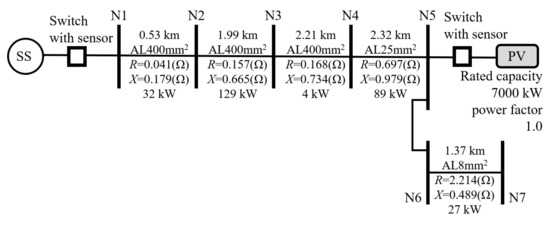
Figure 1.
Actual medium voltage feeder with measured unbalanced voltage.
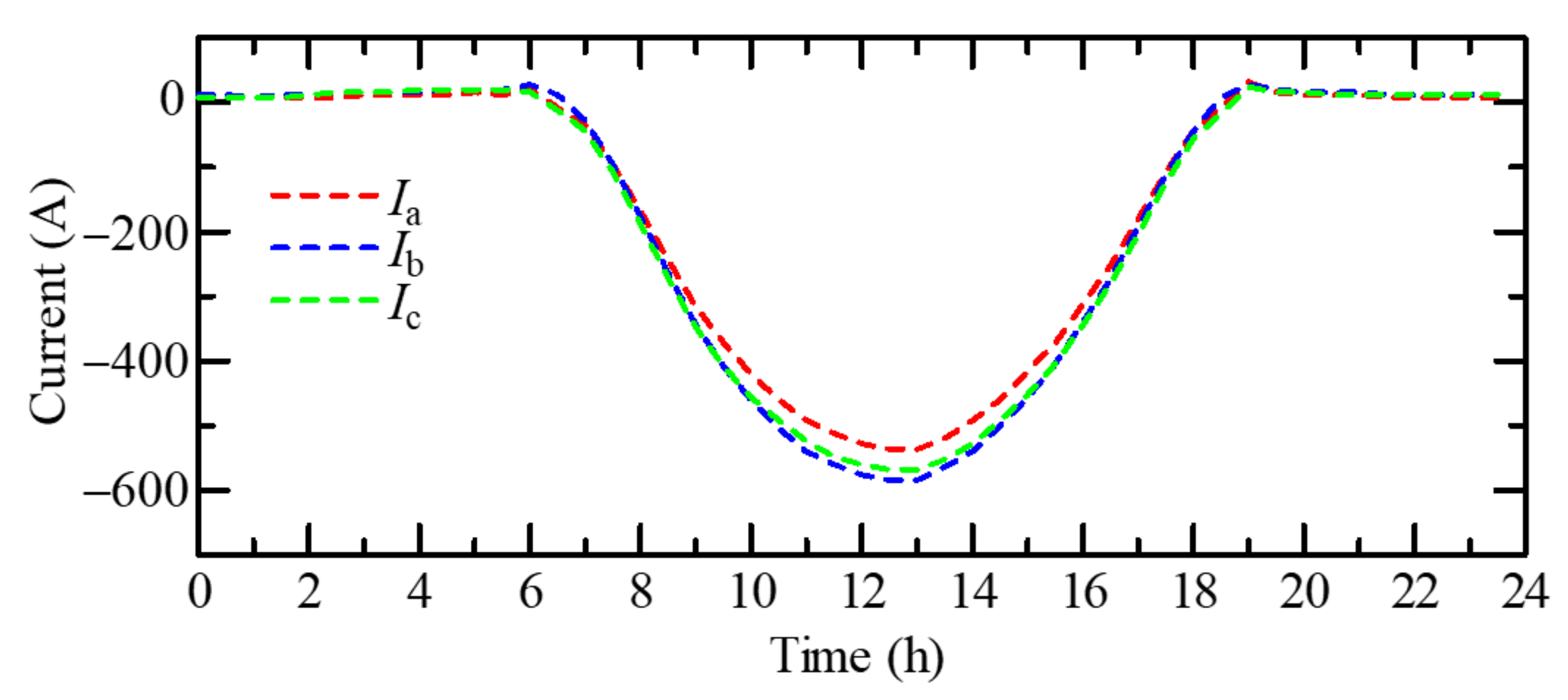
Figure 2 depicts the time variation in the RMS value of the line current measured using a sensor near the substation on 23 April 2017. At night, the current had a positive value that corresponded to the forward power flow. From 6 a.m. to 6 p.m., the current had a negative value owing to the reverse power flow from the large-capacity PV system. By comparing three-phase currents, it could be confirmed that these three-phase currents were slightly unbalanced when the large reverse power flow was measured.
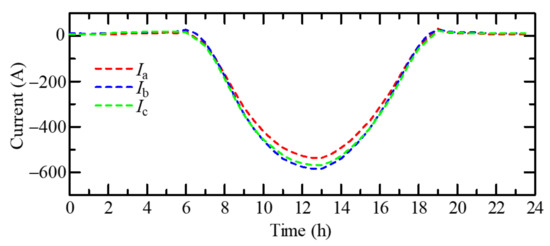
Figure 2.
Time variation in the measured current in an actual distribution system.
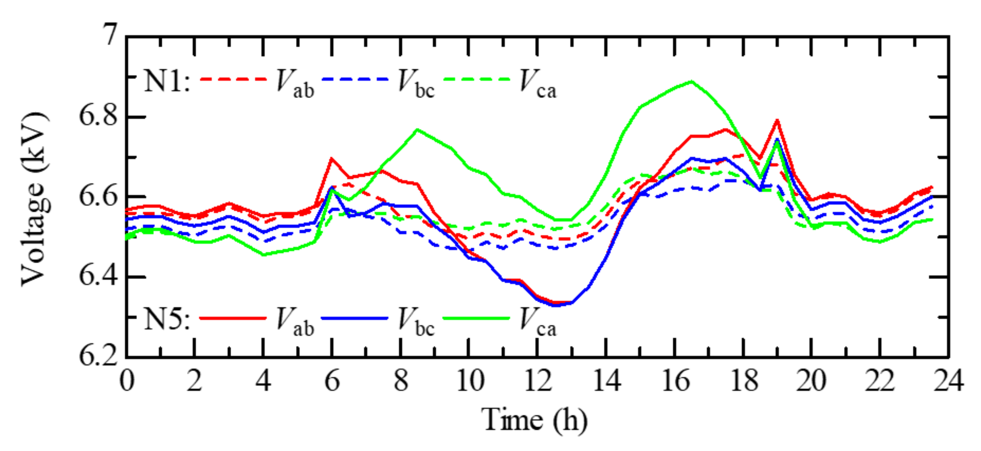
Figure 3 depicts the time variation in the RMS value of line-to-line voltage measured using sensors on the same day, which expresses the voltage unbalance expansion owing to the reverse power flow in the large-capacity PV system. The broken and solid lines indicate the voltage near the substation and PV system, respectively. The voltage unbalance at the substation remained constant throughout the day. In contrast, the voltage in the PV system had a large unbalance when the reverse power flow was large. From 6 a.m. to 9 a.m., when the output of the PV system was smaller than the rated power, the voltage Vca increased, and the voltage Vab and Vbc decreased with an increase in the PV output. The voltage reduction due to the reverse power flow could be explained by the previously mentioned theory [2]. Thereafter, when the PV output further increased, the voltage Vca started to decrease. At around 12 p.m., when the PV output passed through a maximum, there was a difference of approximately 200 V among the three-phase voltages.
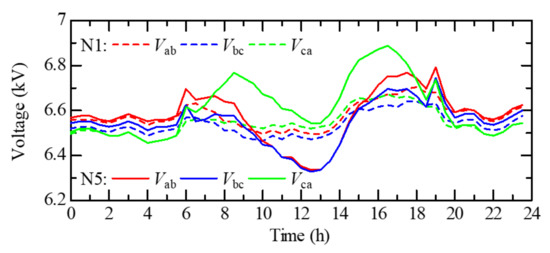
Figure 3.
Time variation in the measured voltage in an actual distribution system.
It was found that the reverse power flow caused a variation in the three-phase voltage during each phase (Vca was different from Vab and Vbc) and expanded the voltage unbalance. The primary purpose of our study is to investigate the mechanism for the expansion of voltage unbalance owing to the large reverse power flow.
3. Mechanism of Unbalanced Voltage Caused by Voltage Reduction due to Reverse Power Flow
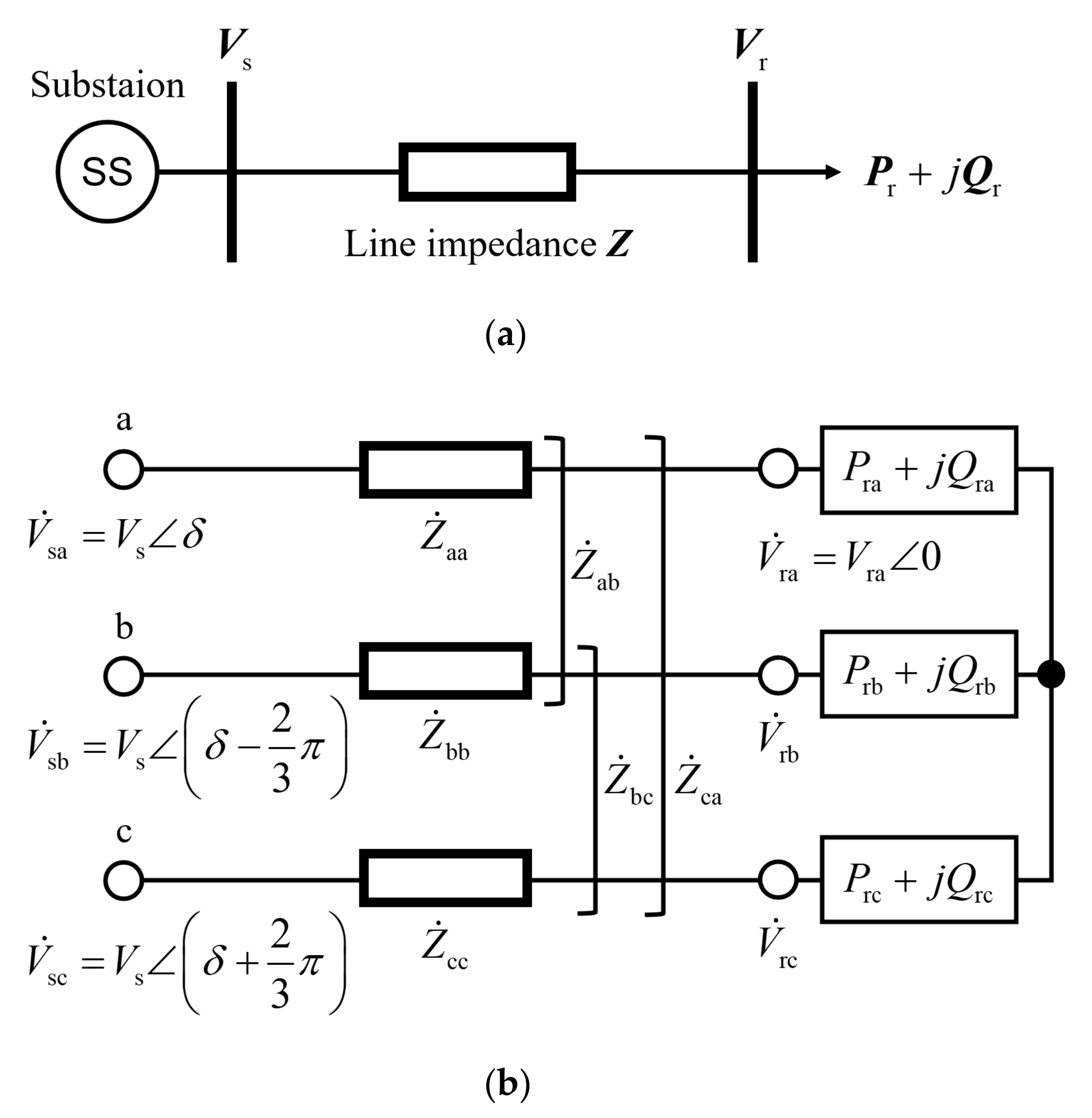
The P–V curve for each phase was derived to clarify the mechanism of the expansion of voltage unbalance. Although the method for deriving the P-V curve is generally well known, the mutual impedance between phases must be considered while deriving the P-V curve for each phase. We derived P-V curves for each phase using a simplified distribution system model as depicted in Figure 4 to theoretically reveal that the voltage unbalance expands with respect to the reverse power flow. The simplified model consists of the sending end, receiving end, and three-phase line impedance. The line impedance is composed of the self-impedance and mutual impedance between the phases, as depicted in Figure 4b. The capacity between wires is neglected because the current flowing in the capacity between wires is sufficiently small compared to the line current. When the active power supplied to the receiving end is negative, it means that a power generation system such as a PV is connected, and the three-phase voltage at the sending end is balanced. As the line impedance is unbalanced, the voltage at the receiving end is three-phase unbalanced, even if the power at the receiving end is three-phase balanced. If the power at the receiving end becomes three-phase unbalanced, then the unbalanced voltage may become severe.

Figure 4.
Simplified distribution system model: (a) single-line diagram; (b) three-phase circuit diagram.
The line current is expressed in terms of the symmetrical components:
where the zero-sequence current is equal to zero because the Japanese distribution system is ungrounded, and a is defined as a phasor rotation operator.
By inserting Equation (1) into Ohm’s law equation, we obtain the voltage drop between the sending and receiving ends.
First, let us consider the P-V curve of the a-phase. The following equation gives the voltage drop of the a-phase:
where
The complex power at the receiving end is given by Equation (6).
By substituting the current unbalance (defined by Equation (7)) into Equation (6) leads to the positive sequence current :
where
By using the current unbalance , Equation (4) can be rewritten as,
By inserting Equation (8) into Equation (10), we obtain the quadratic equation of .
After solving Equation (11), we finally obtain the a-phase voltage .
Equation (12) not only derives the P-V curve for the a-phase receiving end voltage but also relates to the P-V curve for the other phases. By using the phase angle and positive sequence current , which are obtained by substituting and into Equations (8)–(10), we obtain the b-phase and c-phase voltage drops:
where
The complex powers of the b- and c-phases are expressed using the following equations:
By combining Equations (13) and (15), we also obtain Vrb and Vrc, which derive the P-V curve for the b- and c-phase receiving end voltages.
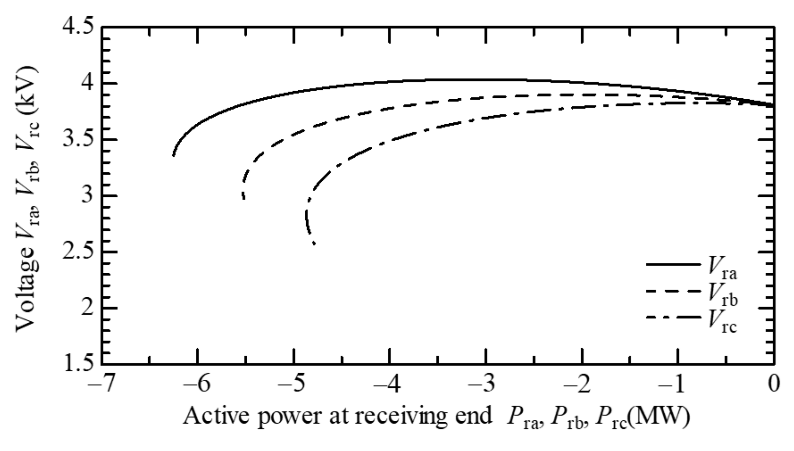
The P-V curve of each phase was drawn by varying the current imbalance ratio . Figure 5 depicts the P-V curves when the three-phase current is balanced, that is, when .The horizontal axis indicates the active power of the receiving end, and the vertical axis indicates the phase voltage. The material of the distribution line was a hard-drawn aluminum-stranded conductor with a length of 5 km and a cross-section of 400 mm2. The three-phase distribution lines were arranged horizontally. The line impedance could be expressed using the following equation:

Figure 5.
P-V curve when the three-phase current is balanced ().
We can see that even if the three-phase current is balanced, the three-phase voltage will be unbalanced because the line impedance is unbalanced. The unbalanced voltage increases with an increase in the reverse power flow, as depicted in Figure 5.
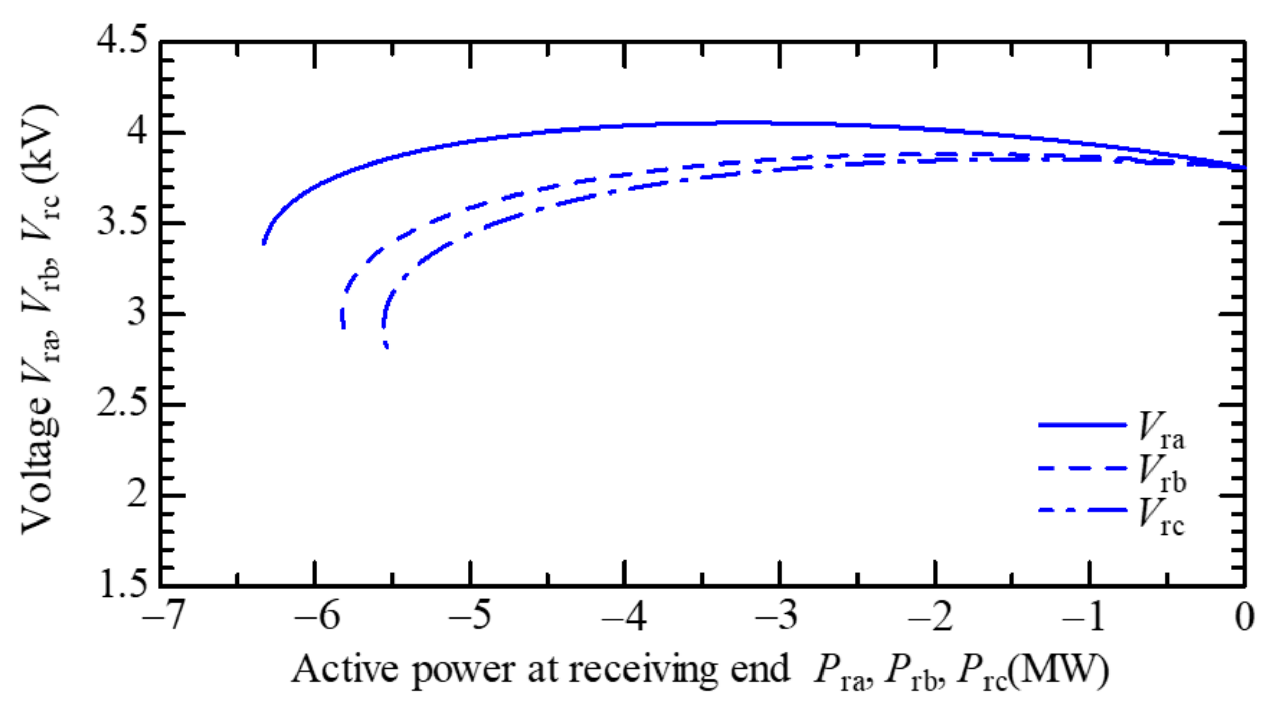
The current unbalance affects the shape of the P-V curves. Figure 6 and Figure 7 indicate the P-V curves when the current unbalance is 0.05 and −0.05, respectively. As the voltage unbalance in Figure 6 is larger than that in Figure 7, the voltage unbalance was found to vary as a function of reverse power flow with respect to the current unbalance . This implies that even if the line impedance is unbalanced, the voltage unbalance can be improved if the current unbalance rate is adjusted appropriately.
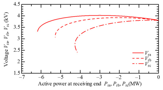
Figure 6.
P-V curve when the three-phase current is balanced ().
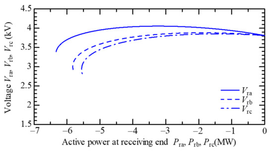
Figure 7.
P-V curve when the three-phase current is balanced ().
4. Improvement of Voltage Unbalance by Current Injection Based on Unbalanced Line Impedance
In this section, we have derived the injection current required to mitigate the expansion of voltage unbalance owing to the reverse power flow. Firstly, we found the relationship between the injection current and the line impedance, which is necessary to alleviate the voltage unbalance. Secondly, we clarified that the required injection current depends on the unbalanced impedance of the distribution line.
4.1. Influence of Current Unbalance on Voltage Unbalance under Unbalanced Line Impedance
As there are several parameters related to the voltage unbalance, certain parameters such as Pra and Qra are assumed to get fixed for the analysis. In this section, we will clarify the influence of current unbalance on the voltage unbalance when the line impedance is balanced or unbalanced.
Figure 8 depicts the relationship between the current unbalance and voltage unbalance when the line impedance is balanced. The balanced line impedance was derived by arranging the three-phase wires in the shape of an equilateral triangle. The voltage unbalance is expressed using the following equation:
where and are the positive and negative sequence voltages at the receiving end. The active and reactive powers of the a-phase at the receiving end were fixed at −1.0 MW and 0, respectively. The voltage unbalance was calculated by changing the real and imaginary parts of the current unbalance in the range of −0.15–0.15.

Figure 8.
Voltage unbalance rate when line impedance is balanced.
From Figure 8, it can be confirmed that when the current unbalance is zero, the voltage unbalance is also zero. The voltage unbalance increases with an increase in the current unbalance , centering on the point where the current unbalance is zero.
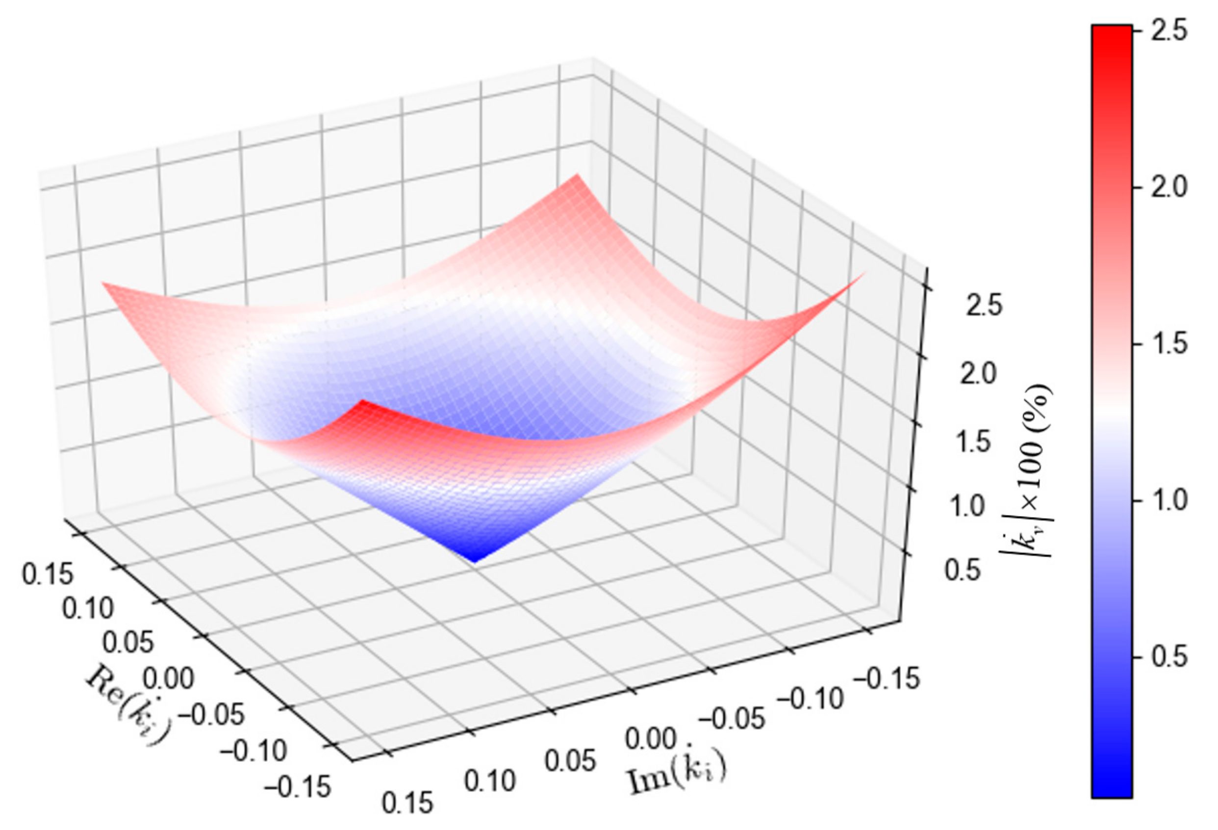
In contrast, when the line impedance is unbalanced, as in Equation (16), it was found that the voltage unbalance is not equal to zero even if the current unbalance is zero, as depicted in Figure 9. It was also found that there is a specific current unbalance at which the voltage unbalance becomes zero. In the case of Figure 9, the voltage unbalance is zero when . Figure 9 depicts the result of fixing the a-phase power Pra + j Qra; however, when the same investigation was performed for other a-phase powers, it was confirmed that the specific current unbalance rate at which the voltage unbalance is zero does not depend on the a-phase power.
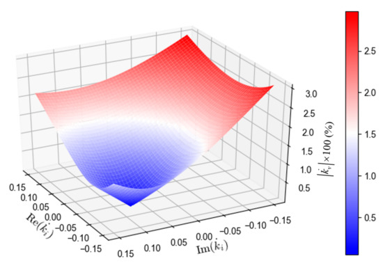
Figure 9.
Voltage unbalance rate when line impedance is unbalanced.
4.2. Current Condition for Minimization of Voltage Unbalance
From the definition of Equation (17), if the negative sequence voltage at the receiving end is controlled to zero, the voltage unbalance is improved to zero. We derived the relationship between the current unbalance and the line impedance at which the voltage unbalance becomes zero. The voltage drop across the sending and receiving ends is expressed in terms of sequence voltage, current, and impedance:
Assuming that the three-phase voltage at the sending end is balanced, . As described above, because the Japanese distribution system is ungrounded, that is, the zero-sequence current is zero, and the negative sequence voltage at the receiving end becomes zero when the following equation is satisfied:
This equation derives the condition of the current unbalance required for the voltage unbalance rate to become zero.
It was confirmed that the current unbalance depicted in Figure 9 is identical to that expressed in Equation (20). This fact indicates that the voltage unbalance rate can be improved to zero by controlling the current unbalance rate according to the line impedance unbalance.
5. Examples of Application of the Proposed Method
5.1. Improvement of Voltage Unbalance by Single-Phase Reactors
We have proposed the connection of single-phase reactors to the receiving end of the distribution line to control the current unbalance, as described in the previous section, for improving the voltage unbalance. It is assumed that the capacity of the single-phase reactor connected between each phase depicted in Figure 10 can be independent.
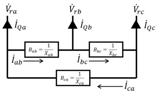
Figure 10.
Single phase reactors connected to the receiving end of distribution line.
The required susceptance Bab, Bbc, and Bca of the single-phase reactors was calculated so that the current unbalance is expressed by Equation (20). Assuming that the unbalance voltage at the receiving end is improved by connecting the reactors, we obtain the reactor currents expressed in terms of the receiving end voltage Vra and the susceptance.
By transforming Equation (21), the positive and negative currents were obtained as follows:
The unbalanced rate of the line current was determined by the three-phase current of the load, PV, and the single-phase reactors so that the current unbalance satisfied the following equation:
where and represent the positive and negative sequence line currents, respectively, without the single-phase reactors.
Given the total capacity of the single-phase reactors, the susceptance of each reactor could be determined. Rearrangement of Equation (23) leads to Equation (24).
where . If the right side of Equation (24) is designated by , the required susceptances could be obtained using simultaneous equations.
This equation indicates that the symmetrical components of the line impedance and the current lead to the susceptance of single-phase reactors to improve the voltage unbalance rate.
5.2. Case Study
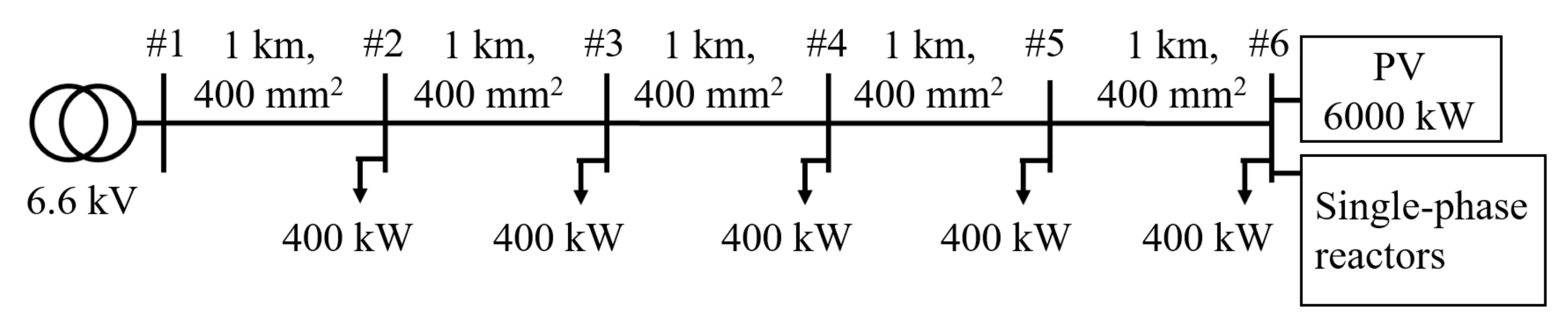
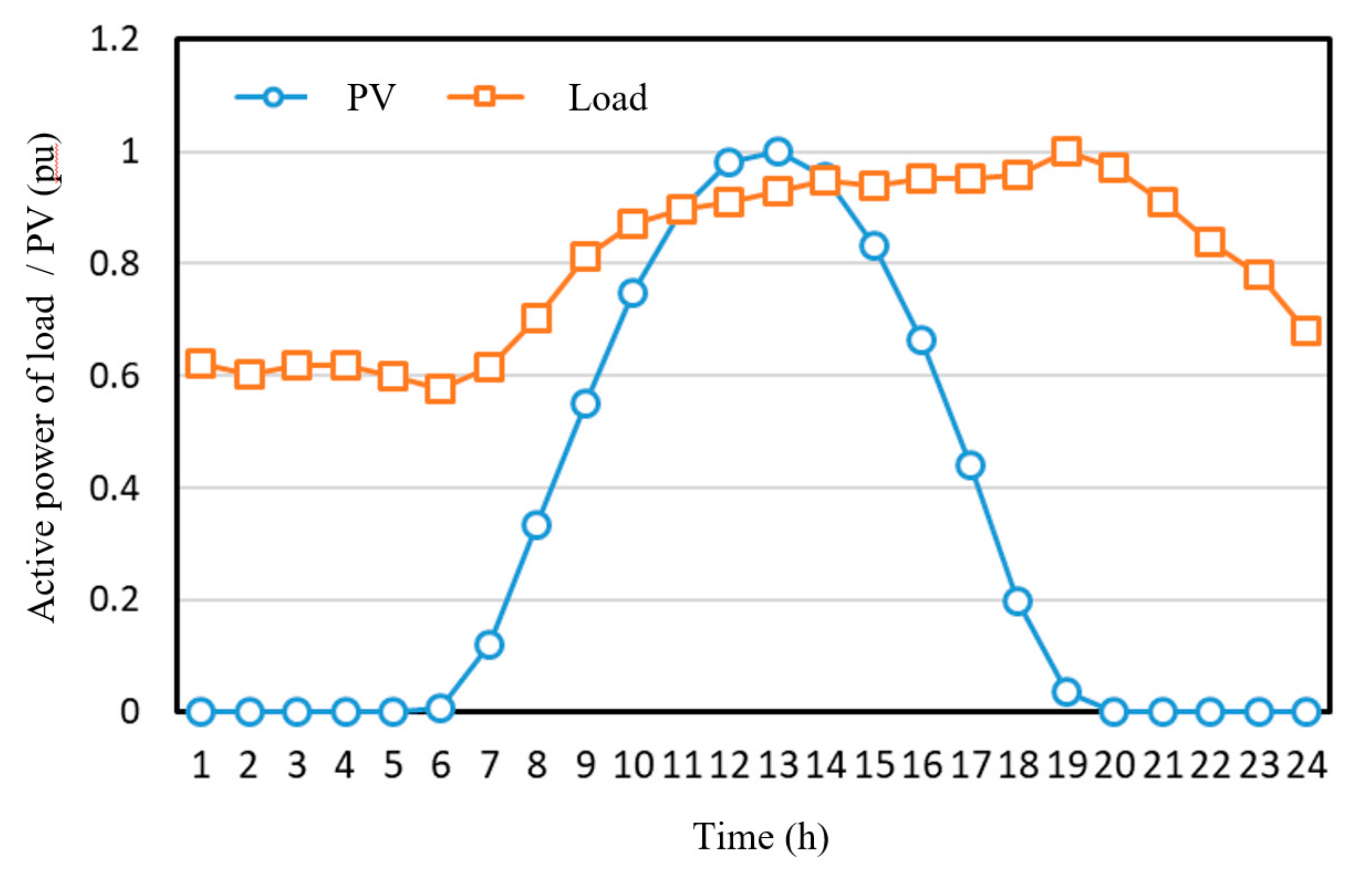
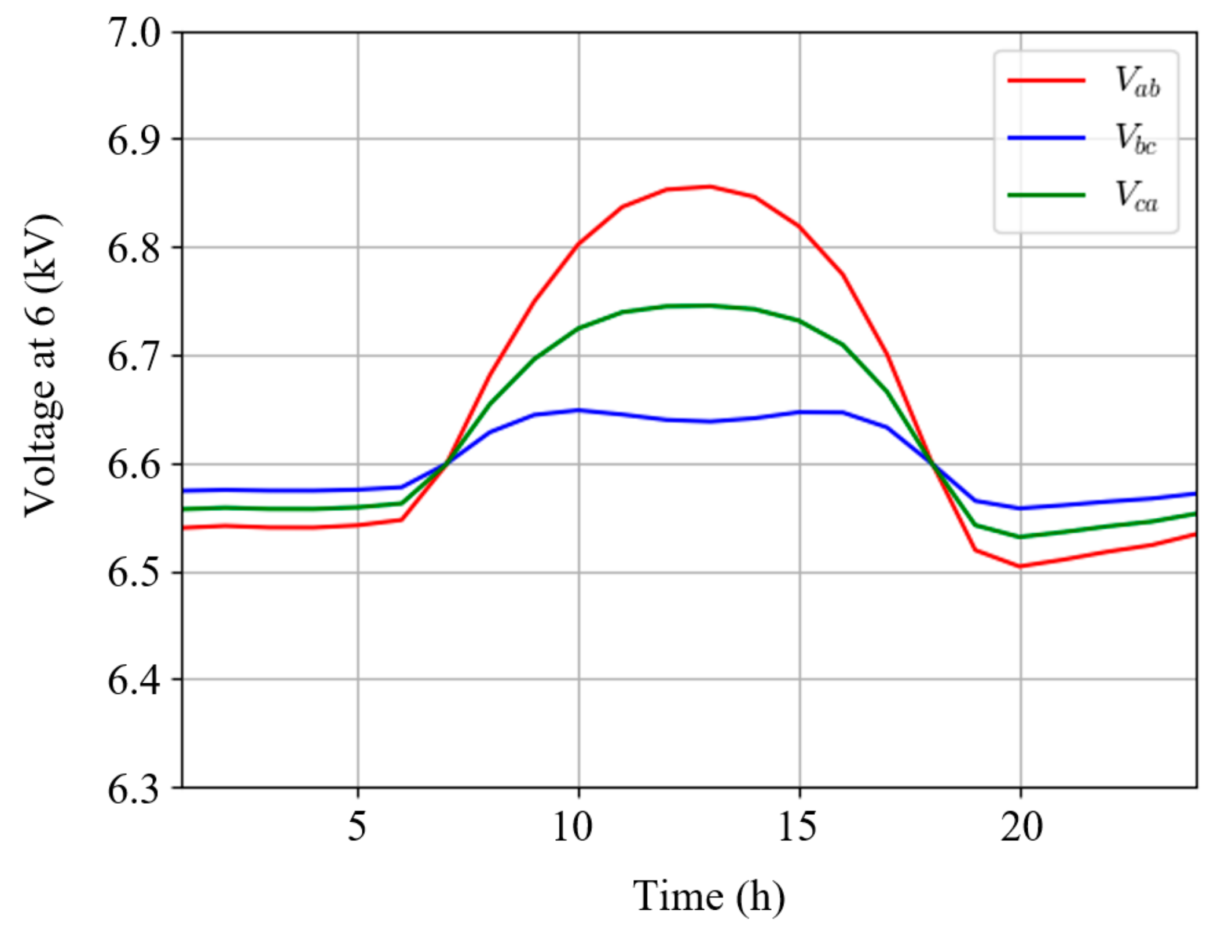
It has been confirmed that the susceptance of the single-phase reactors described in Equation (25) contributes to the suppression of the voltage unbalance owing to the large reverse power flow. The simulation model depicted in Figure 11 is composed of unbalanced line impedance, loads, a 6000 kW PV system, and the proposed single-phase reactors. The line impedance is expressed by Equation (16). The load and PV system are three-phase balanced, respectively. Figure 12 depicts the time variation in the power of the load and the PV system during daytime. We calculated the receiving end voltage when the single-phase reactors were not connected, as depicted in Figure 13. The time variation in the receiving end voltage indicates that the voltage unbalance increases with respect to the output of the PV system.

Figure 11.
Simulation model with a large PV system and single-phase reactors.
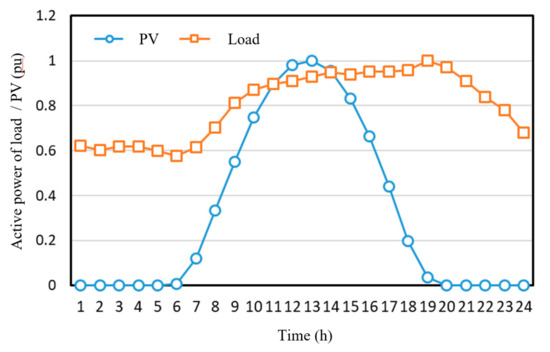
Figure 12.
Time variation in the active power of load and PV.
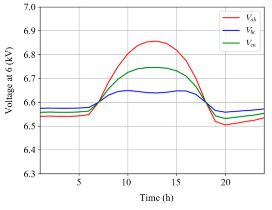
Figure 13.
Time variation in voltage at 6 without single-phase reactors.
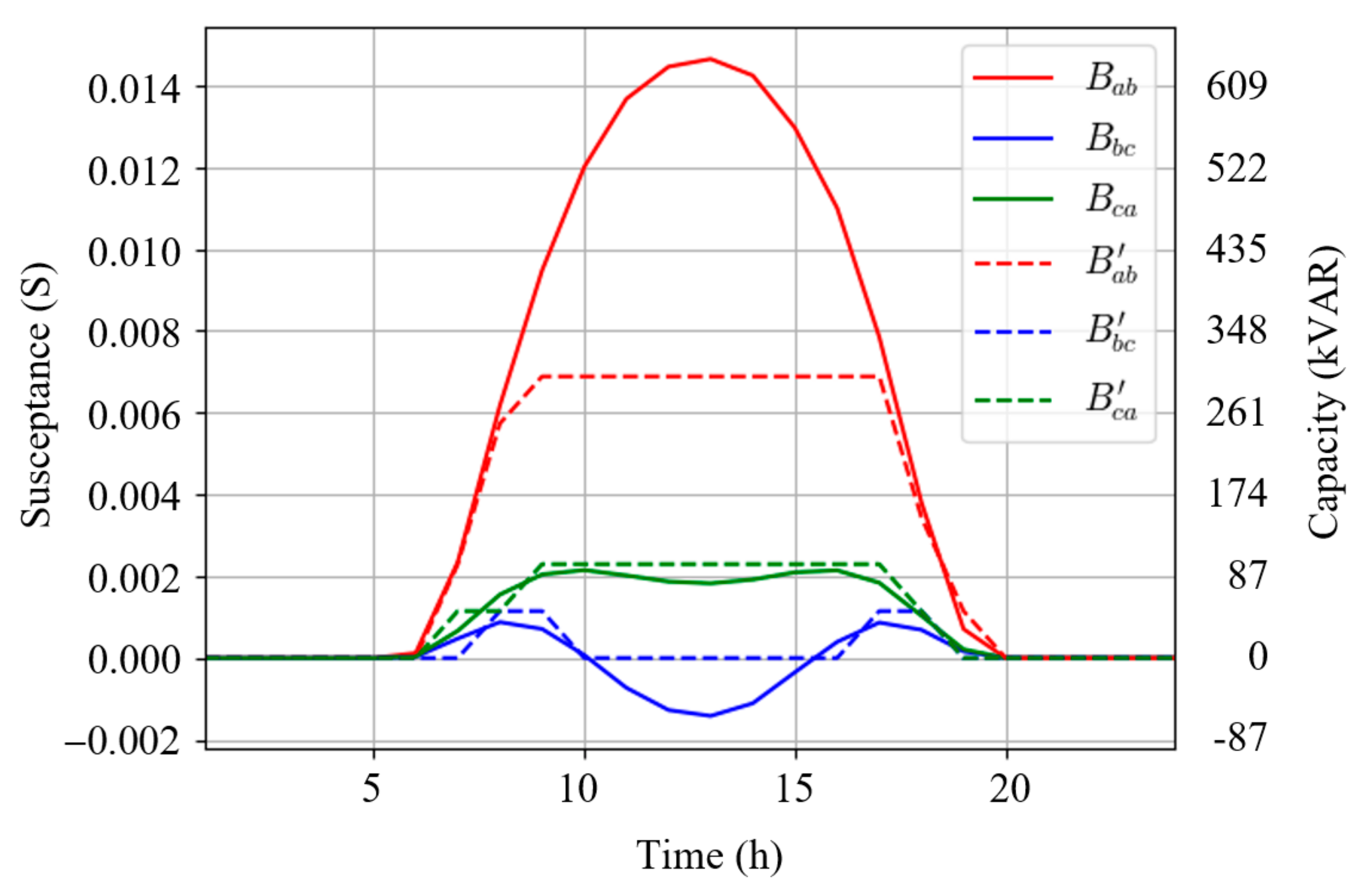
Assuming that the currents and injected into the power receiving point could be detected, the required susceptance value of each single-phase reactor could be obtained from Equation (25). Figure 14 depicts the time variation in the ideal susceptance of single-phase reactors using solid lines. The positive and negative susceptance corresponds to the reactor and capacitor, respectively. However, it is unrealistic to continuously change the susceptance by using a single-phase reactor. It is also not feasible to switch and control the reactor and capacitor to control the positive and negative susceptances. Therefore, to control the susceptance discretely, we propose turning on and off the single-phase reactors, as indicated by the broken lines in Figure 14. We assumed that the capacity of one single-phase reactor is 50 kVAR and that it could be expanded up to 300 kVAR by connecting it in parallel. The maximum capacity of the single-phase reactor was determined by considering the size of the actual equipment. It is assumed that the single-phase reactors to be connected could be easily switched.
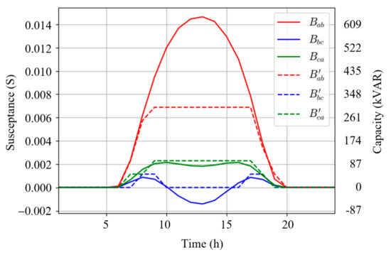
Figure 14.
Time variation in susceptance of single-phase reactors.
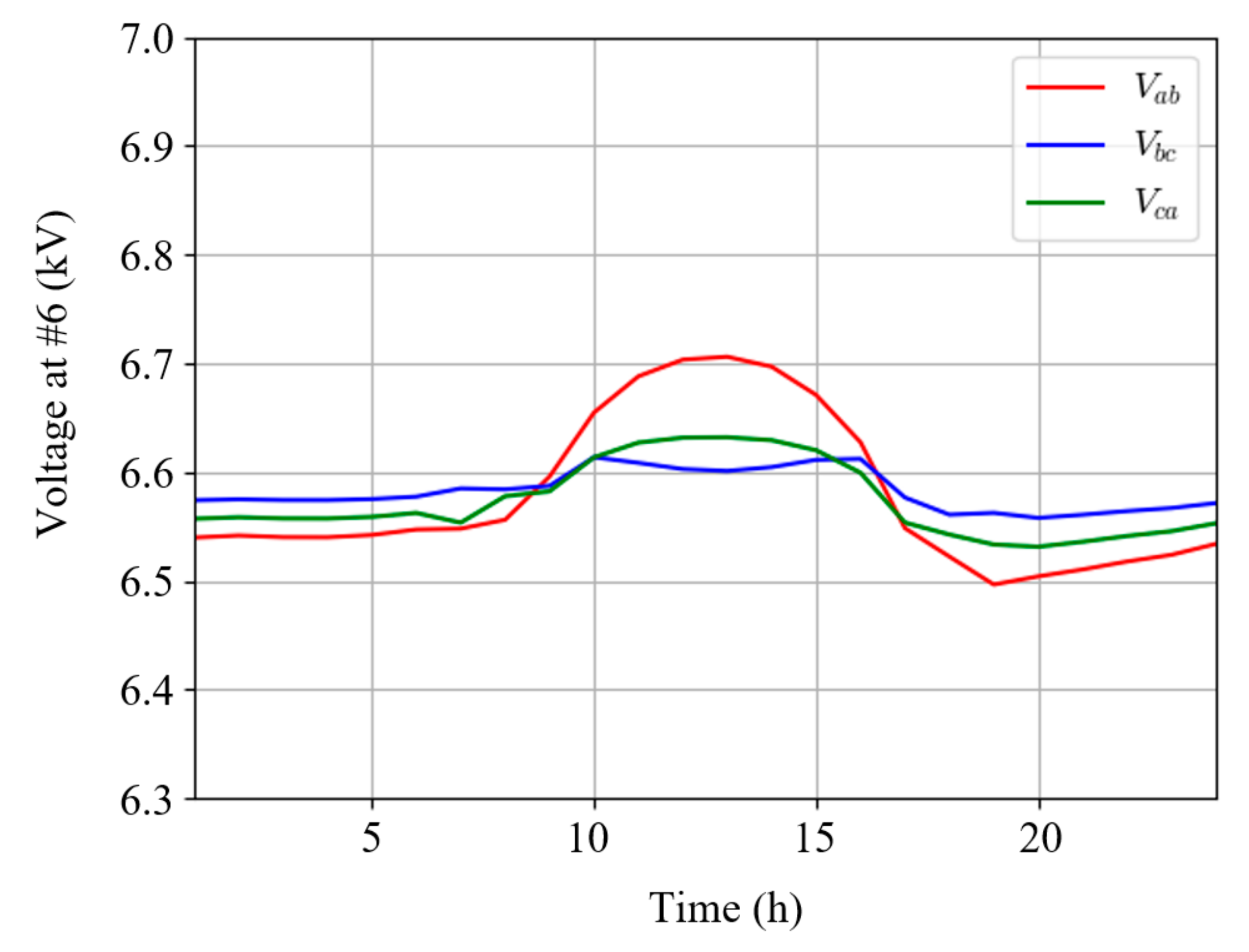
Figure 15 depicts that the voltage unbalance can be improved by discretely controlling the single-phase reactors. An increase in the maximum capacity of the single-phase reactor could further improve the voltage unbalance rate.
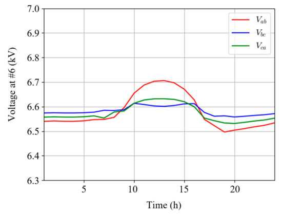
Figure 15.
Time variation in voltage at #6 with single-phase reactors.
5.3. Summary of Issues Related to the Proposed Method
We have proposed a method to determine the injection current to improve the voltage unbalance based on the unbalanced impedance of the distribution line and described its application for reactor control as an example of application. The future tasks of the proposed method are as follows.
- It is necessary to provide examples of application to other distribution system models to strongly demonstrate the effectiveness of the proposed method.
- Another application of the proposed current injection method is necessary to demonstrate the effectiveness of our proposal. If the proposed method is applied to the current control of inverters, it can be compared with other voltage unbalance countermeasure techniques using inverters.
- Since the economic and technical advantages of the proposed method vary greatly depending on the type of target to which it is applied, it is a challenge to clarify the appropriate target for application.
6. Conclusions
The measurement of large voltage unbalance in an actual distribution system owing to the reverse power flow has been presented in this study. In addition, an injection current to mitigate the voltage unbalance has been proposed. The primary results obtained are as follows:
- From the measurement of the voltage unbalance that occurs owing to the large reverse power flow, it was clarified that this is a complicated phenomenon because the voltage reduction occurred depending on the phase.
- By drawing a P-V curve for each phase in a distribution line with unbalanced line impedance, we observed that the expansion of voltage unbalance occurred with respect to an increase in the reverse power flow.
- It was clarified that the injection current for alleviating the voltage unbalance could be derived from the unbalanced line impedance.
- As an example, the simulation clarified that the voltage unbalance could be improved by the injection current by using single-phase reactors, which are controlled by the proposed method.
Author Contributions
This study is a collaborative effort among the authors, and all authors have read and agreed to the published version of the manuscript. Conceptualization, D.I.; data curation, T.F.; formal analysis, D.I.; investigation, T.F.; methodology, D.I. and T.T.; project administration, T.H.; resources, J.M. and D.N.; software, D.I. and T.T.; supervision, T.H.; validation, T.T. and T.H.; visualization, D.I. and T.F.; writing—original draft, D.I.; writing—review and editing, D.I., T.F., T.T., T.H., J.M. and D.N. All authors have read and agreed to the published version of the manuscript.
Funding
This research received no external funding.
Institutional Review Board Statement
Not applicable.
Informed Consent Statement
Not applicable.
Conflicts of Interest
The authors declare no conflict of interest.
References
- Masters, C.L. Voltage rise: The big issue when connecting embedded generation to long 11 kV overhead lines. Power Eng. J. 2002, 16, 5–12. [Google Scholar] [CrossRef]
- Iioka, D.; Fujii, T.; Tanaka, T.; Harimoto, T.; Motoyama, J. Voltage Reduction in Medium Voltage Distribution Systems using Constant Power Factor Control of PV PCS. Int. J. Electr. Power Energy Syst. 2019, 113, 411–418. [Google Scholar] [CrossRef]
- Matsumura, T.; Tsukamoto, M.; Tsusaka, A.; Yukita, K.; Goto, Y.; Yokomizu, Y.; Tatewaki, K.; Iioka, D.; Shimizu, H.; Kanazawa, Y.; et al. Line-End Voltage and Voltage Profile along Power Distribution Line with Large-Power Photovoltaic Generation System. Int. J. Photoenergy 2019, 2019, 1263480. [Google Scholar] [CrossRef]
- Iioka, D.; Fujii, T.; Orihara, D.; Tanaka, T.; Harimoto, T.; Shimada, A.; Goto, T.; Kubuki, M. Voltage reduction due to reverse power flow in distribution feeder with photovoltaic system. Energies 2020, 13, 5430. [Google Scholar] [CrossRef]
- Haque, M.M.; Wolfs, P. A review of high PV penetrations in LV distribution networks: Present status, impacts and mitigation measures. Renew. Sustain. Energy Rev. 2016, 62, 1195–1208. [Google Scholar] [CrossRef]
- Zhang, D.; An, R.; Wu, T. Effect of voltage unbalance and distortion on the loss characteristics of three-phase cage induction motor. IET Electr. Power Appl. 2018, 12, 264–270. [Google Scholar] [CrossRef]
- Hernández, J.C.; Ortega, M.J.; De la Cruz, J.; Vera, D. Guidelines for the technical assessment of harmonic, flicker and unbalance emission limits for PV-distributed generation. Electr. Power Syst. Res. 2011, 81, 1247–1257. [Google Scholar] [CrossRef]
- Garcia, P.A.N.; Pereira, J.L.R.; Carneiro, S.; da Costa, V.M.; Martins, N. Three-phase power flow calculations using the current injection method. IEEE Trans. Power Syst. 2000, 15, 508–514. [Google Scholar] [CrossRef]
- Cheng, C.S.; Shirmohammadi, D. A three-phase power flow method for real-time distribution system analysis. IEEE Trans. Power Syst. 1995, 10, 671–679. [Google Scholar] [CrossRef]
- Liao, H.; Milanovic, J.V. Methodology for the analysis of voltage unbalance in networks with single-phase distributed generation. IET Gener. Transm. Distrib. 2017, 11, 550–559. [Google Scholar] [CrossRef] [Green Version]
- Shahnia, F.; Ghosh, A.; Ledwich, G.; Zare, F. Predicting Voltage Unbalance Impacts of Plug-in Electric Vehicles Penetration in Residential Low-voltage Distribution Networks. Electr. Power Compon. Syst. 2013, 41, 1594–1616. [Google Scholar] [CrossRef]
- Mulenga, E.; Bollen, M.H.J.; Etherden, N. A review of hosting capacity quantification methods for photovoltaics in low-voltage distribution grids. Int. J. Electr. Power Energy Syst. 2020, 115, 105445. [Google Scholar] [CrossRef]
- Iioka, D.; Miura, K.; Machida, M.; Kikuchi, S.; Imanaka, M.; Baba, J.; Takagi, M.; Asano, H. Hosting capacity of large scale PV power station in future distribution networks. In Proceedings of the 2017 IEEE Innovative Smart Grid Technologies—Asia (ISGT-Asia), Auckland, New Zealand, 4–7 December 2017; pp. 1–6. [Google Scholar] [CrossRef]
- Kikuchi, S.; Machida, M.; Tamura, J.; Imanaka, M.; Baba, J.; Iioka, D.; Miura, K.; Takagi, M.; Asano, H. Hosting capacity analysis of many distributed photovoltaic systems in future distribution networks. In Proceedings of the 2017 IEEE Innovative Smart Grid Technologies—Asia (ISGT-Asia), Auckland, New Zealand, 4–7 December 2017; pp. 1–5. [Google Scholar] [CrossRef]
- Ismael, S.M.; Abdel Aleem, S.H.E.; Abdelaziz, A.Y.; Zobaa, A.F. State-of-the-art of hosting capacity in modern power systems with distributed generation. Renew. Energy 2019, 130, 1002–1020. [Google Scholar] [CrossRef]
- Ruiz-Rodriguez, F.J.; Hernández, J.C.; Jurado, F. Voltage unbalance assessment in secondary radial distribution networks with single-phase photovoltaic systems. Int. J. Electr. Power Energy Syst. 2015, 64, 646–654. [Google Scholar] [CrossRef]
- Jouanne, A.v.; Banerjee, B. Assessment of voltage unbalance. IEEE Trans. Power Deliv. 2001, 16, 782–790. [Google Scholar] [CrossRef]
- Shahnia, F.; Wolfs, P.J.; Ghosh, A. Voltage Unbalance Reduction in Low Voltage Feeders by Dynamic Switching of Residential Customers Among Three Phases. IEEE Trans. Smart Grid 2014, 5, 1318–1327. [Google Scholar] [CrossRef] [Green Version]
- Douglass, P.J.; Trintis, I.; Munk-Nielsen, S. Voltage unbalance compensation with smart three-phase loads. In Proceedings of the Power Systems Computation Conference (PSCC), Genoa, Italy, 20–24 June 2016. [Google Scholar] [CrossRef]
- Taher, S.A.; Bagherpour, R. A new approach for optimal capacitor placement and sizing in unbalanced distorted distribution systems using hybrid honey bee colony algorithm. Int. J. Electr. Power Energy Syst. 2013, 49, 430–448. [Google Scholar] [CrossRef]
- Su, X.; Masoum, M.A.S.; Wolfs, P.J. Optimal PV Inverter Reactive Power Control and Real Power Curtailment to Improve Performance of Unbalanced Four-Wire LV Distribution Networks. IEEE Trans. Sustain. Energy 2014, 5, 967–977. [Google Scholar] [CrossRef]
- Neukirchner, L.; Görbe, P.; Magyar, A. Voltage unbalance reduction in the domestic distribution area using asymmetric inverters. J. Clean. Prod. 2017, 142, 1710–1720. [Google Scholar] [CrossRef]
- Bozalakov, D.; Mnati, M.J.; Laveyne, J.; Desmet, J.; Vandevelde, L. Battery Storage Integration in Voltage Unbalance and Overvoltage Mitigation Control Strategies and Its Impact on the Power Quality. Energies 2019, 12, 1501. [Google Scholar] [CrossRef] [Green Version]
- Chua, K.H.; Lim, Y.S.; Taylor, P.; Morris, S.; Wong, J. Energy Storage System for Mitigating Voltage Unbalance on Low-Voltage Networks With Photovoltaic Systems. IEEE Trans. Power Deliv. 2012, 27, 1783–1790. [Google Scholar] [CrossRef]
- Yamane, K.; Iioka, D.; Saitoh, H. Three-phase voltage control method by single-phase distributed generators connected to islanded distribution network. Electr. Eng. Jpn. 2019, 207, 14–22. [Google Scholar] [CrossRef]
- Meersman, B.; Renders, B.; Degroote, L.; Vandoorn, T.; Vandevelde, L. Three-phase inverter-connected DG-units and voltage unbalance. Electr. Power Syst. Res. 2011, 81, 899–906. [Google Scholar] [CrossRef] [Green Version]
- Weckx, S.; Driesen, J. Load Balancing With EV Chargers and PV Inverters in Unbalanced Distribution Grids. IEEE Trans. Sustain. Energy 2015, 6, 635–643. [Google Scholar] [CrossRef] [Green Version]
- Shigenobu, R.; Nakadomari, A.; Hong, Y.Y.; Mandal, P.; Takahashi, H.; Senjyu, T. Optimization of Voltage Unbalance Compensation by Smart Inverter. Energies 2020, 13, 4623. [Google Scholar] [CrossRef]
- Li, K.; Liu, J.; Wang, Z.; Wei, B. Strategies and Operating Point Optimization of STATCOM Control for Voltage Unbalance Mitigation in Three-Phase Three-Wire Systems. IEEE Trans. Power Deliv. 2007, 22, 413–422. [Google Scholar] [CrossRef]
- Shahnia, F.; Ghosh, A.; Ledwich, G.; Zare, F. Voltage unbalance improvement in low voltage residential feeders with rooftop PVs using custom power devices. Int. J. Electr. Power Energy Syst. 2014, 55, 362–377. [Google Scholar] [CrossRef]
- Ren, B.; Sun, X.; Chen, S.; Liu, H. A Compensation Control Scheme of Voltage Unbalance Using a Combined Three-Phase Inverter in an Islanded Microgrid. Energies 2018, 11, 2486. [Google Scholar] [CrossRef] [Green Version]


Publisher’s Note: MDPI stays neutral with regard to jurisdictional claims in published maps and institutional affiliations. |
© 2021 by the authors. Licensee MDPI, Basel, Switzerland. This article is an open access article distributed under the terms and conditions of the Creative Commons Attribution (CC BY) license (https://creativecommons.org/licenses/by/4.0/).