Article

Characterization of Pd60Cu40 Composite Membrane Prepared by a Reverse Build-Up Method for Hydrogen Purification

1
Department of Chemical Science and Engineering, School of Materials and Chemical Technology, Tokyo Institute of Technology, 2-12-1, Ōokayama, Meguro-ku, Tokyo 152-8550, Japan
2
Department of Transdisciplinary Science and Engineering, School of Environment and Society, Tokyo Institute of Technology, 2-12-1, Ōokayama, Meguro-ku, Tokyo 152-8550, Japan
3
Sanno Co., Ltd., 5-8-8, Tsunashima-Higashi, Kouhoku-ku, Yokohama 223-0052, Japan
4
Laboratory for Zero-Carbon Energy, Institute of Innovative Research, Tokyo Institute of Technology (Tokyo Tech), 2-12-1, Ōokayama, Meguro-ku, Tokyo 152-8550, Japan
*
Author to whom correspondence should be addressed.
Energies 2021, 14(24), 8262; https://doi.org/10.3390/en14248262
Submission received: 8 November 2021 / Revised: 23 November 2021 / Accepted: 1 December 2021 / Published: 8 December 2021
(This article belongs to the Special Issue Optimized Heat and Mass Exchangers for Sorption Cooling Systems)

Abstract

:
A thin Pd-based H2-permeable membrane is required to produce high-purity H2 with high efficiency. In this study, a porous Ni-supported Pd60Cu40 composite H2-permeable membrane was developed using a reverse build-up method to produce economical H2 purification. The thickness of the Pd60Cu40 alloy layer produced by the improved membrane production process reached 1.0 μm; it was thinner than the layer obtained in a previous study (3.7 μm). The membrane was characterized by scanning electron microscope, inductively coupled plasma optical emission spectrometer, H2 permeation test, and Auger microprobe analysis. The permeation tests were performed at 300–320 °C and 50–100 kPa with H2 introduced from the primary side. The H2 permeation flux was stable up to ~320 °C. The n-value was determined to be 1.0. The H2 permeance of the membrane was 2.70 × 10⁻⁶ mol m−2 s−1 Pa−1.0 at 320 °C, after 30 h, similar to those of other 2.2-µm-thick and 3.7-µm-thick Pd60Cu40 composite membranes, suggesting that the adsorption and dissociation reaction processes on the PdCu alloy surface were rate-limiting. The Pd cost of the membrane was estimated to be ~1/30 of the Pd cost of the pure Pd60Cu40 membrane.

1. Introduction

With the aim of creating a low-carbon society, the demand for H2 as a next-generation energy carrier has increased [1]. H2 is generally produced by methane steam reforming reactions (MSR) [2,3]. However, because the product is a mixture, H2 must be separated and purified from the gases [4]. To obtain high-purity H2 for industrial use, membrane separation methods are effective [5]. H2 separation membranes composed of ceramics, polymers, and metals can selectively separate H2 gas [6], with those made of Pd metal reportedly exhibiting excellent H2 permeability and selectivity [7,8]. The superior H2 permeability and selectivity of dense Pd to other materials is due to the difference in the mechanism by which H2 permeates through membranes. Pd has high catalytic activity for H2 dissociation [9]. Since H2 permeates through the Pd-based membrane by the solution-diffusion mechanism [10], H2 with higher purity can be obtained, than from other membranes [6]. Furthermore, Pd-based membranes can continuously separate H2 gas because of their high H2 selectivity [11]. This feature allows the reaction system to de-equilibrate the MSR reaction of Equations (1)–(3) to the formation of H2, resulting in an improved H2 yield and the recovery of more H2, facilitating effective feedstock utilization [12,13].
CH4 + H2O CO + 3H2
CO + H2O CO2 + H2
CH4 + 2H2O CO2 + 4H2
For these reasons, the use of Pd-based H2-permeable membranes enables the supply of high-purity H2 (≥99.99%) [14,15], which is required for H2 fuel cell vehicles (FCVs) [16]. However, it is difficult to produce high-purity H2 using materials for membranes other than Pd, therefore, Pd-based devices have been widely developed for advanced energy applications in industry [17,18]. However, the widespread use of Pd-based devices is restricted by the high material cost of Pd [19]. To solve this problem, reducing the material cost of the membrane by alloying it with Au [20,21], Ag [22,23], Cu [24,25,26], and Ru [27,28] have been explored to address these issues. Among these elements, Cu, which is remarkably inexpensive, has been studied. Cu has the additional advantages of resistance to H2S [29], higher durability in thermal cycling tests than PdAg alloys and other materials, and prevents H2 embrittlement, which is a problem associated with pure Pd membranes [30]. In particular, the Pd60Cu40 wt.% (Pd47Cu53 at.%) alloy has the highest H2 permeability at 350 °C among the PdCu alloys reported thus far [8,31]. For these reasons, H2-permeable membranes of Pd60Cu40 alloy have been developed.
To promote the industrial feasibility of Pd-based H2-permeable membranes, a method to reduce the Pd requirement by making the Pd alloy layer thinner has been investigated [22,32,33]. Making the Pd alloy layer thinner reduces the material cost and lowers the H2 permeation resistance in the membrane, thus improving the performance. However, although the material cost can be reduced by thinning the Pd alloy layer, the membrane’s durability is significantly reduced, hampering its industrial application as a stand-alone membrane. Therefore, Pd-based composite membranes formed on a porous support consisting of Vycor glass, ceramics, and porous stainless steel (PSS) have been developed [6]. Among these materials, composite membranes supported by tube-type porous ceramics are commonly used [34].
Conversely, ceramic supports are vulnerable to prolonged use and thermal cycling. They are also prone to delamination from the thin Pd layer [35], limiting the processing size of the membrane [36,37,38]. Therefore, the development of ceramic-supported composite H2-permeable membranes is limited when considering the large area of the membranes to realize large scale H2 production. Therefore, a composite membrane with a Ni support layer is considered in this study. The use of metal supports can solve the problem of ceramic-supported composite membranes. In addition, it is confirmed it prepares larger areas than the case of ceramic tube-type membrane reactors. Therefore, it is expected to obtain H2 permeability and selectivity, allowing large-scale H2 production. In particular, Ni metal has an advantage in that it can easily be formed on a Pd alloy membrane at a low cost by electroplating. Furthermore, since Ni’s thermal expansion coefficient is similar to that of Pd, peeling is unlikely to occur between the Ni support layer and the Pd alloy layer.
In this study, a metal-supported composite H2-permeable membrane suitable for large-scale H2 production was developed using a reverse build-up method [39]. Conventional Pd alloy freestanding membranes are fabricated using the rolling method, but typical membrane thicknesses are greater than 20 μm, resulting in high cost and low H2 permeability [22,26]. In addition, in the commonly used electroless plating (ELP) method of forming a Pd alloy layer on porous ceramic supports, it is not easy to control the thickness of the Pd alloy layer. It is generally known that a minimum thickness of 5 µm is required to produce a defect-free membrane [40]. As a result, the uniformity of the membrane is low, and there are problems in achieving both H2 permeability and H2 selectivity [6].
In contrast, in the reverse build-up method, the Pd alloy layer is deposited on a smooth surface to form a metal support, to achieve a Pd alloy layer with high smoothness and uniformity. This method allows the thickness of the Pd alloy layer to be reduced to a few microns or less and allows the fabrication of a smooth and thinner membrane with a thickness of up to approximately 1.0 µm membrane without pinholes. In the authors’ previous study [41], a Pd60Cu40 alloy layer fabricated using the reverse build-up method was successfully thinned down to 3.7 μm. In this study, a metal-supported composite H2-permeable membrane was developed with a Pd60Cu40 alloy layer thinned down to 1.0 μm, by improving the membrane production method. Therefore, this research has succeeded in fabricating a thin 1.0-µm Pd60Cu40 layer, which was previously impossible, by improving the process of primer layer formation. Furthermore, an investigation of the effect of thinning the Pd alloy layer on H2 permeability and selectivity was conducted. Finally, the impact of operating this low-cost thin membrane at high temperatures was investigated and evaluated to expand its industrial applications.

2. Materials and Methods

2.1. Reverse Build-Up Method

Composite membranes were developed using the reverse build-up method based on previous studies [39,41]. One of the most critical steps in the fabrication of thin composite membranes is the formation of a primer layer. In the reverse build-up method, the surface condition of the primer layer is carried over to the Pd60Cu40 alloy layer, so the thin Pd60Cu40 alloy layer formed by sputtering in the next step, reflects the effect of surface irregularities and defects in the primer layer. Therefore, the H2 permeability and selectivity of the composite membrane are greatly affected. Moreover, the conventional resin and spin-coating conditions are examined to form a smooth and uniform primer layer. The improved process was carried out as follows.
The cleaning method of a glass substrate was improved against the conventional method, to form a primer layer with a smoother and more uniform surface. First, a 72 × 52 mm substrate (Matsunami Glass Co., Ltd., Osaka, Japan) was cleaned with ethanol in an ultrasonic generator for 30 min. Then, one side of the substrate was wiped, and the substrate was installed in the spin-coater with the wiped side facing down. The surface was then dried by spinning it at 1000 rpm for 5 min to prepare the primer layer.
Next, a primer layer of the polymer was formed on the glass substrate by spin coating. The polymer solution was prepared according to the following procedure: 1 g of S-Lec BX-L butyral resin (Sekisui Chemical Co., Ltd., Osaka, Japan) was added to 25 g of toluene, and the mixture was stirred at room temperature for 6 h. Then, 25 g of ethanol was added so that the weight ratio of toluene to ethanol was 1:1, and the mixture was stirred at room temperature for 12 h. After the polymer solution was thoroughly mixed, the glass substrate was placed in a spin coater (Active Co., Ltd., Saitama, Japan). The polymer solution (5 mL) was dropped onto the glass substrate using a syringe (Terumo Co., Ltd., Tokyo, Japan) and spread evenly over the entire surface. The substrate was spun at 100 rpm for 500 s, and a primer layer was prepared on the glass substrate. The coated substrate was stored in a desiccator at room temperature and allowed to dry naturally for at least 24 h. The above procedure improved the formation of the primer layer, which is an important step in the fabrication of thin membranes by magnetron sputtering. It was then possible to form a 1.0 μm Pd60Cu40 alloy layer, which was difficult to fabricate in a previous study.
In this study, a Pd60Cu40 alloy layer was introduced as an H2-permeable membrane. Pd60Cu40 alloy (Pd60Cu40, 99.9 wt.%, Kojundo Chemical Laboratory Co., Ltd., Saitama, Japan) target with a diameter of 100 mm was used for high-frequency magnetron sputtering (Takao Co., Ltd., Kanagawa, Japan). The glass substrate on which the primer layer was formed by spin coating was installed in the sputtering apparatus as the cathode. Sputtering was performed at a pressure of Ar under vacuuming for 48 min.
A porous Ni support was formed by electroplating to improve the mechanical strength of the thin Pd60Cu40 alloy layer. Next, 2 L of 60% Ni sulfamate solution was prepared as an electroplating bath. In addition, 5 mL of a Ni-plating additive, based on a previous study [42], was added dropwise to the bath. The temperature of the electroplating bath, rotation speed of the magnetic stirrer, and pH of the bath were adjusted to 50 °C, 800 rpm, and <5.0, respectively. A pure Ni plate (99%, Nilaco Co., Ltd., Tokyo, Japan) was used as the anode, and the substrate sputtered with a thin Pd60Cu40 alloy layer was used as the cathode. The anode and cathode plate were fixed with jigs, electricity was supplied from the power supply device (YAMABISHI Co., Ltd., Tokyo, Japan), and the current density was 0.01 A cm−2 for 1 h.
Finally, the primer layer was dissolved in ethanol, and the composite membrane was removed from the glass substrate to complete the process.

2.2. Sample Characterization

The composite membranes fabricated by the reverse build-up method in this study were named PCNX, where X is the thickness of the Pd60Cu40 alloy layer (µm). Scanning electron microscopy (SEM, Hitachi Co., Ltd., Tokyo, Japan) was used to observe the fabricated composite membranes. Cross-sectional SEM images were used to determine the thickness of each membrane layer.
PdCu alloy membrane samples were prepared to investigate the composition of the fabricated membranes. The samples were obtained by magnetron sputtering on a glass substrate directly at Ar pressure of 0.2 Pa for 24 min. The chemical composition (mg L−1) of the obtained PdCu alloy membrane samples was evaluated using an inductively coupled plasma optical emission spectrometer (ICP-OES, Agilent Technologies Co., Ltd., Cheadle, UK).
Figure 1a shows the experimental set-up used for the H2 permeation tests. Figure 1b shows a cross-sectional view of the composite membrane fabricated in this study. The obtained composite membrane was cut into a circular shape, as shown in Figure 1c, and the diameter of the cut membrane sample was 12 mm. The sample was sandwiched between two stainless steel gaskets (316 L stainless steel VCR face seal fitting, 1/4 in Swagelok Co., Ltd., Solon, OH, USA). Thus, the membrane sample’s effective surface area for H2 permeation was the inner part of the membrane surface that was not on the gasket. The gasket had outer and inner diameters of 11.9 and 5.6 mm, respectively. The composite membrane was then installed in the test chamber of the permeation test apparatus with the surface of the Pd60Cu40 alloy layer on the primary side of the test chamber. The area around the composite membrane was covered with a mantle heater, and thermocouples were installed to adjust the composite membrane temperature.
The properties of the PCN1.0 membrane fabricated in this study and the parameters used in the H2 permeation test are listed in Table 1. The composition of the PdCu alloy (wt.%), the thickness of the PdCu alloy layer (µm) and porous Ni support layer (µm), and the total membrane thickness (µm) of the PCN1.0 membrane are shown. The effective diameter of the membrane sample matched the inner diameter of the gasket. Therefore, the effective membrane surface area of the membrane sample, determined based on the inner diameter, is shown in Table 1.
The flow rate of each gas used in the H2 permeation test was adjusted using a mass flow controller (MFC, KOFLOC Co., Ltd., Kyoto, Japan). A mixture of 20 mL min−1 of H2 and 4–20 mL min−1 of He was supplied to the primary side, and 100 mL min−1 of N2 as a sweep gas was provided to the secondary side. The H2 and He permeated through the composite membrane, and the N2 sweep gas was sent to a gas chromatograph with a thermal conductivity detector (TCD-GC, SHIMADZU Co., Ltd., Kyoto, Japan) for compositional analysis.
Measurements were made at four temperatures of 300, 305, 310, and 320 °C and five pressures of 50, 60, 70, 84, and 100 kPa for the H2 partial pressure, ΔPH2n (Pan) to determine the pressure exponent n called the n-value, referring to a previous study [41]. The n-value explains the exponential dependence of the H2 permeation flux on H2 partial pressure and usually ranges from 0.50 to 1.0. Subsequently, H2 permeation tests were performed on the PCN1.0 membrane at 320 °C. The H2 partial pressure difference (ΔPH2n (Pan)) between the primary and secondary, is defined by Equation (4) below:
Δ P H 2 n = P H 2 , feed n P H 2 , perm n   [ Pa n ]   ( 0.50 n 1.0 )
where PH2,feed [Pa] is the partial pressure of H2 on the primary side of the chamber, PH2,perm [Pa] is the partial pressure of H2 on the secondary side of the chamber. PH2,perm is significantly smaller than PH2,feed and thus, it can be ignored. It is well known that the mechanism of H2 permeation through Pd-based membranes generally follows the solution-diffusion mechanism, and the driving force is the H2 partial pressure difference [6,43]. The steps of H2 permeation are as follows: H2 is adsorbed on the surface of the Pd membrane and dissociates into hydrogen atoms. The atoms then dissolve into the Pd bulk and diffuse through the bulk. Next, hydrogen atoms associate on the Pd surface and recombine into H2. Finally, H2 is desorbed from the surface [6,43].
The H2 permeation flux on the secondary side of the test chamber, JH2 (mol m−2 s−1), was assumed to be defined by Equation (5):
J H 2 = φ H 2 L ( P H 2 , feed n P H 2 , perm n )   [ mol   m 2   s 1 ]
where L (µm) is the Pd60Cu40 alloy layer thickness, φH2 (mol m−1 s−1 Pa-n) is the H2 permeability coefficient, and φH2/L (mol m−2 s−1 Pa-n) is the H2 permeance. The relationship between the Pd-based membrane thickness and the n-value has been reported [6]. When diffusion in Pd bulk is the rate-limiting step, the n-value is 0.5. This always follows Sievert’s Law in a thick (5 µm <) Pd-based membrane, as shown in Equation (6) [44].
J H 2 = φ H 2 L ( P H 2 , feed 0.5 P H 2 , perm 0.5 )   [ mol   m 2   s 1 ]   ( n = 0.5 )
Conversely, when the n-value is near 1.0, it matches the Pd-alloy membranes’ rate-limiting surface reaction (adsorption and dissociation reaction).
The selectivity of H2 over He, αH2/He (−), was calculated using Equation (7). Here, φHe [mol m−1 s−1 Pa-n] is the He permeability coefficient, and n of φH2 and φHe is 1.0.
α H 2 / He = φ H 2 φ He   ( n = 1.0 )
The relationship between φH2 and T can be generally described by Arrhenius law. The temperature dependence of the H2 permeability coefficient can be defined by Equation (8) [45]:
φ H 2 = A exp ( E a R T )   [ mol   m 1   s 1   Pa - n ]
where R is the universal gas constant, 8.31 J mol−1 K−1, and T is the absolute temperature (K). The activation energy, Ea (kJ mol−1), and the pre-exponential factor at 300–320 °C, A, were obtained from Equation (8). Further, Equation (9) can be obtained from Equation (8). Then based on Equation (8), ln(φH2/L) and the reciprocal of temperature, 1/T (K−1), have a linear relationship.
ln ( φ H 2 L ) = E a R T + ln ( A L )
When H2-permeable membranes are used in combination with particulate devices such as fuel cells, they must be used at high temperatures. Finally, a high-temperature measurement was performed during the H2 permeation test, at 320 °C, with PCN1.0, to investigate the cause of the degradation of the membrane performance at high temperatures (400 °C). It is known that metal interdiffusion progresses at high temperatures, and the membrane performance is significantly degraded [46]. A change in the performance of PCN1.0 during the high-temperature operation was observed. The surface of the PdCu alloy layer and the cross-section of PCN1.0 were analyzed after the H2 permeation test to observe the phenomenon of metal interdiffusion using an FE Auger microprobe (JEOL Co., Ltd., Tokyo, Japan).

3. Results and Discussion

3.1. Sample Characterization

Figure 2 shows the SEM images of the prepared PCN1.0 membrane, being: (a) surface of the Pd60Cu40 alloy layer, (b) surface of the porous Ni layer, and (c) cross-section of PCN1.0. As shown in Figure 2a, no noticeable scratches or pinholes were observed on the Pd60Cu40 alloy surface layer. From Figure 2c, the thickness of the developed PCN1.0 membrane was determined to be 1.0 μm for the Pd60Cu40 alloy layer and 12 μm for the porous Ni support layer. Using the reverse build-up method, a composite membrane with a thin Pd60Cu40 alloy layer was successfully developed.
The composition of the Pd60Cu40 alloy layer formed by magnetron sputtering was analyzed using ICP-OES. The elemental ratio (at.%) and the weight ratio (wt.%) of Pd and Cu, respectively, were determined using the ICP-OES analytical results. The analytical and calculation results are presented in Table 2. The results confirmed that the Pd60Cu40 alloy membrane formed by magnetron sputtering consisted of Pd60Cu40 wt.% (Pd47Cu53 at.%), and that there was no change in the Pd60Cu40 alloy ratio during the membrane deposition process by magnetron sputtering.

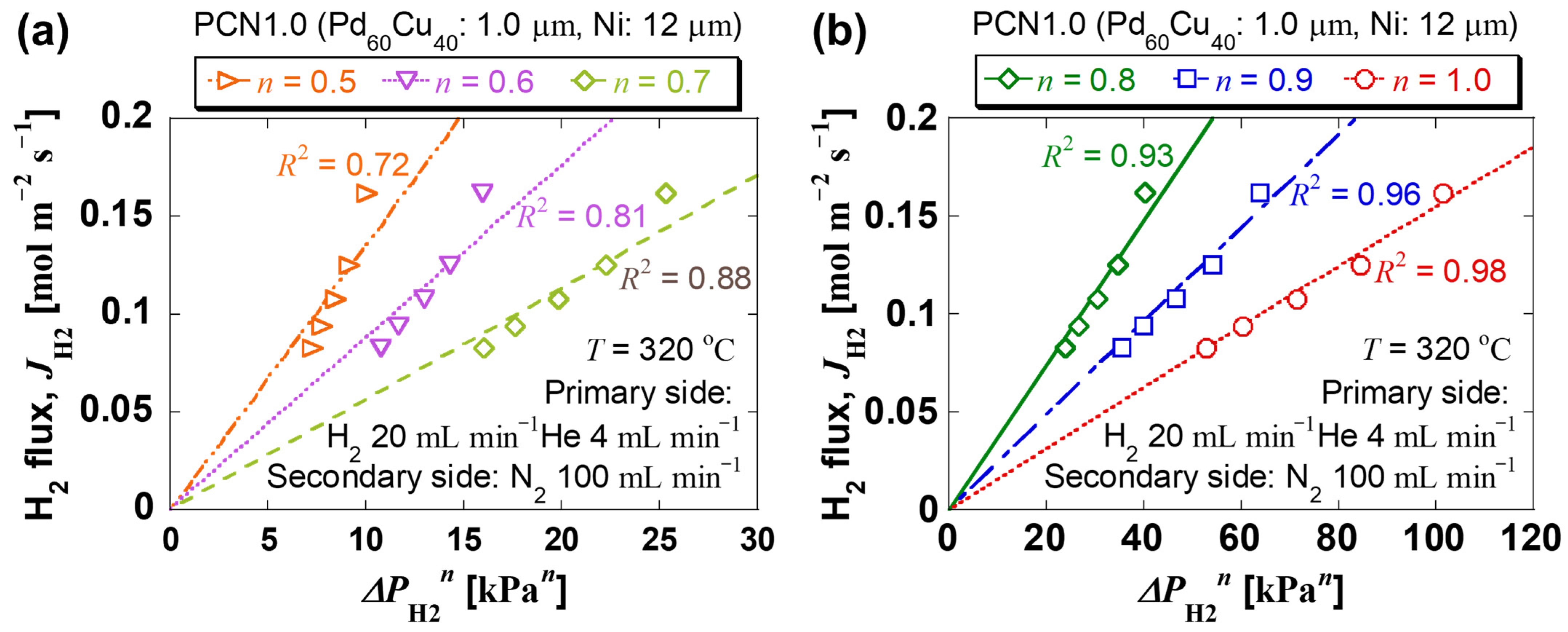
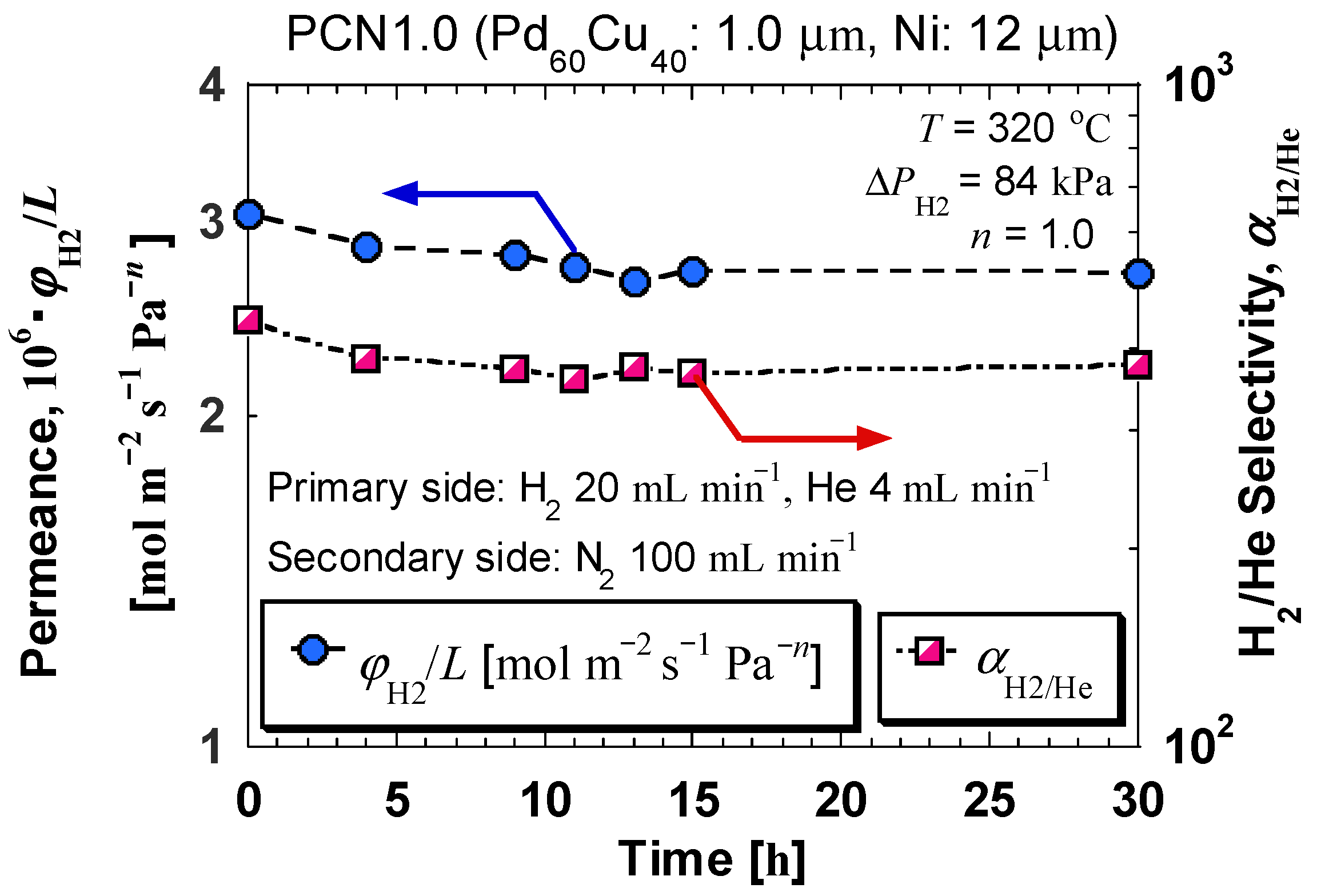
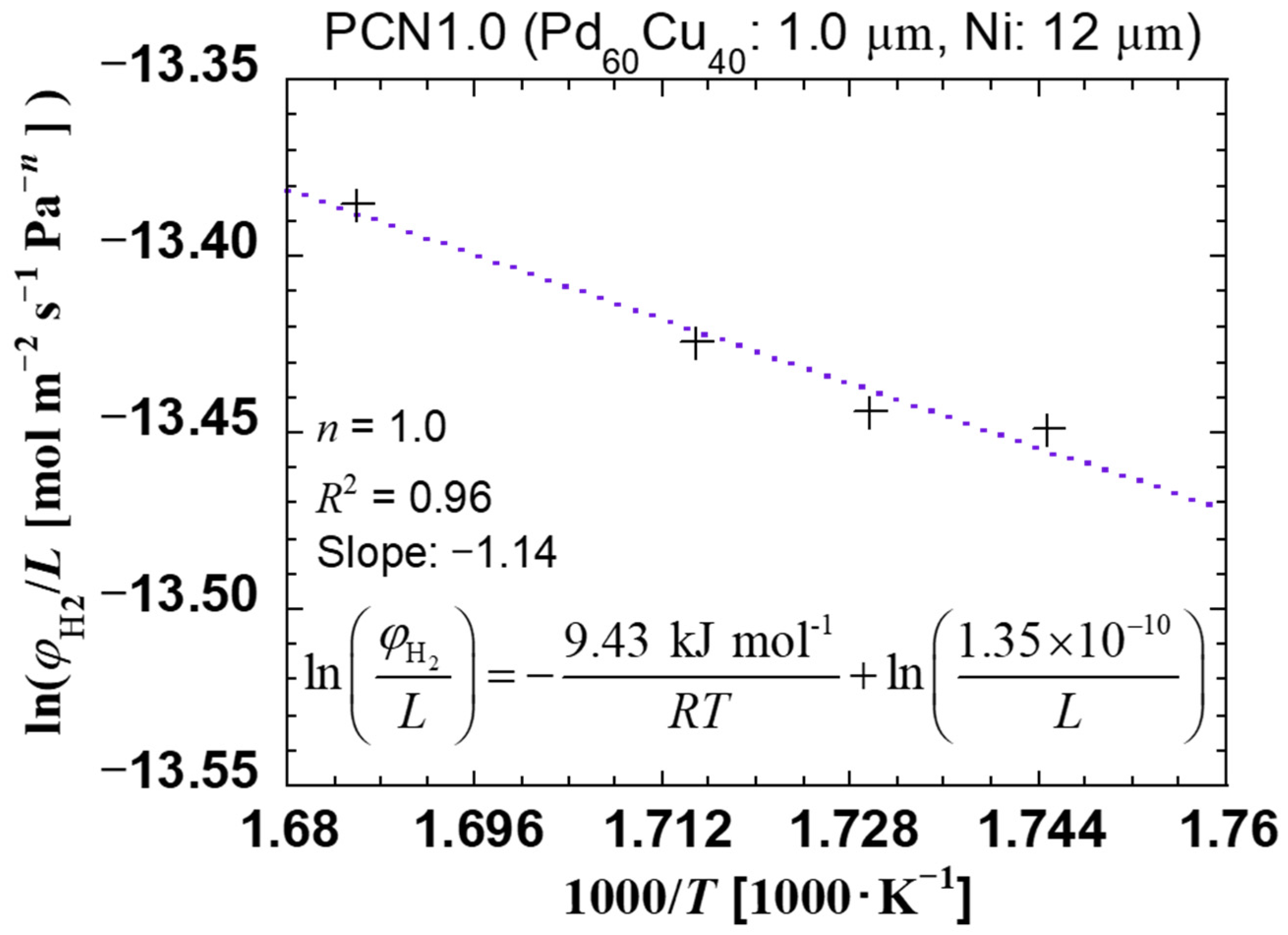
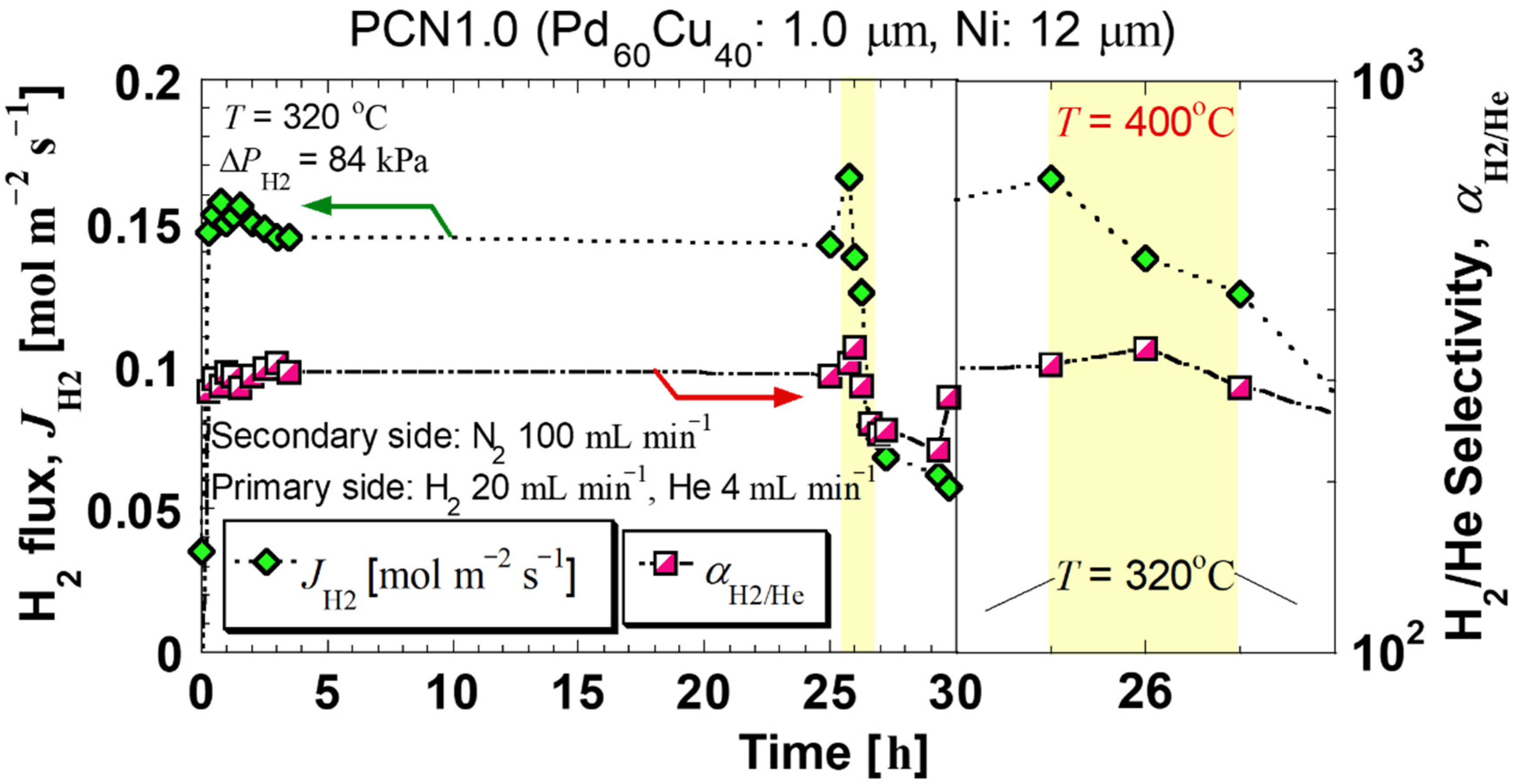
3.2. Evaluation of H2 Permeation Measurement

The obtained PCN1.0 membrane was tested for H2 permeation at ΔPH2 = 50, 60, 70, 84, and 100 kPa at 300, 305, 310, and 320 °C. The n-value can be obtained by measuring the H2 permeation flux, JH2 at different PH2 values, and feed. Figure 3 shows the results of JH2 versus ΔPH2 for n = 0.5, 0.6, 0.7, 0.8, 0.9, and 1.0, at 320 °C. The pressure dependence of JH2 was investigated to determine the n-value of the PCN1.0 membrane. The coefficient of determination R2 was closest to 1 and showed a linear form when n = 1.0. The n-value of 1.0 was also typical for the other thin membranes reported in other studies [19,32], confirming that this result of n = 1.0 wase appropriate. The other results at 300, 305, and 310 °C also showed a shape similar to that shown in Figure 3, with the graph at n = 1.0 having the best linear match.
Figure 4 shows the H2 permeance (n = 1.0) calculated based on Equation (5), φH2/L, and H2/He selectivity calculated based on Equation (7), αH2/He, as a function of time after reaching 320 °C. A few hours after the start of the test, the values of φH2/L and αH2/He were stable. After 30 h, φH2/L and αH2/He were 2.70 × 10⁻⁶ mol m−2 s−1 Pa−1.0 and 377, respectively, indicating high H2 permeability and selectivity. The values of αH2/He were similar to those reported in other studies [47]. It was suggested that the effect of membrane pinholes was negligible.
Figure 5 shows the relationship between the inverse of temperature, 1/T (K), and ln(φH2/L) based on Equation (9).
From the results of the Arrhenius plot shown in Figure 5, the activation energy, Ea, and pre-exponential factor at 300–320 °C, A, were determined. The value of Ea was calculated to be 9.43 kJ mol−1. The value of Ea was similar to that of other thin membranes studied [22].
Table 3 compares the H2 permeability and selectivity of the thin membranes reported in other studies. The PCN1.0 membrane prepared in this study demonstrated high H2 permeance, H2 permeability coefficient, and H2/He selectivity at 320 °C.
Next, the H2 permeation performance and membrane thickness of the PCN1.0, PCN2.2, and PCN3.7 membranes were developed using the reverse build-up method and pure Pd60Cu40 alloy membranes prepared by the conventional rolling method were compared (Table 4).
The H2 permeance of a pure Pd60Cu40 (thickness: 25.4 µm) alloy membrane at 320 °C was determined using the values of H2 permeance at temperatures of ~320 °C in the literature [58,59]. Additionally, the H2 permeation flux was calculated by multiplying that value by the pressure value reported in the literature. Furthermore, the H2 permeance at 320 °C and ΔPH2 = 84 kPa was calculated by dividing the flux value by the H2 partial pressure difference of 84 kPa, which was the experimental condition used in this study. It was confirmed that the H2 permeation flux value was improved by 18% compared with the PCN1.0 membrane and the pure Pd60Cu40 alloy membrane. Because the Pd60Cu40 alloy layer thickness was reduced to 1.0/25.4, the overall reduction in Pd usage by ~1/30 was achieved.
Comparison of the PCN1.0, PCN2.2, and PCN3.7 membranes revealed that the H2 permeance values were almost unchanged, suggesting that the adsorption and dissociation reaction processes on the PdCu alloy surface were rate-limiting. Therefore, it is suggested that these PCN membranes have nearly the exact value of H2 permeance due to the pronounced rate-limiting condition of the surface reaction. Consequently, it was confirmed that the performance of the Pd alloy itself can be evaluated in terms of surface reaction by thinning down to ~1 µm, as in this study.

3.3. Analysis of the Membrane after H2 Permeation Test

The H2 permeation flux and H2/He selectivity of the PCN1.0 were stable at 320 °C. Therefore, it was investigated whether the membrane could be operated at a high temperature (400 °C). Figure 6 illustrates the change in H2 permeation flux and H2/He selectivity with time when the H2 permeation test was continued at 320 °C for 25 h continuously, then increased to 400 °C after one hour and then decreased back to 320 °C.
When the temperature was raised to 400 °C, the performance increased immediately but quickly deteriorated, and the H2 permeation flux decreased by approximately 40% compared with that before the temperature was raised. The performance did not return to normal when the temperature was increased to 320 °C again, suggesting that the membrane had degraded. The main reason for the degradation of performance after high-temperature measurement was thought to be either the change in the crystal structure or the intermetallic diffusion. However, since the crystal structure did not change from the reported phase diagram [19], the cause of the degradation was concluded to be intermetallic diffusion. Therefore, the surface of the PdCu alloy layer of the PCN1.0 membrane after the measurement in Figure 6 was analyzed.
Figure 7 shows the SEM images of the surface of the PdCu alloy layer analyzed by Auger microprobe and the results of Auger profiles. The i, ii, and iii points were randomly selected and analyzed on the surface of the PdCu alloy layer before the H2 permeation test. The points iv, v, and vi were randomly selected on the surface of the PdCu alloy layer after the H2 permeation test.
Ni was not detected on the PdCu alloy surface before the H2 permeation test. However, Ni was observed on the surface of the PdCu alloy layer after the permeation test, and the concentration ratio of Pd significantly decreased (Figure 7d). Furthermore, on the PdCu alloy surface after the H2 permeation test, similar Ni ratios were detected at all three locations (iv v, vi), suggesting that the diffusion of Ni into the PdCu layer occurred throughout the entire PdCu alloy layer (Figure 7d).
Next, the ratio of each atom in the PCN1.0 cross-section to the depth direction was investigated with respect to the PdCu alloy surface. Figure 8 shows the Auger microprobe analysis results of PCN1.0 before and after the H2 permeation test at 320–400 °C. From the cross-sectional SEM image, the zero point in the depth direction was determined to be the surface of the PdCu alloy layer.
Comparing the results before and after the H2 permeation test in the PdCu alloy layer, the ratio of Pd and Cu decreased after the H2 permeation test, and the balance of Ni increased (Figure 8c). In addition, Ni diffused near the PdCu alloy surface and was uniformly distributed at the layer interface (Figure 8c). Intermetallic interdiffusion between the layers occurred before and after the H2 permeation tests of the PCN1.0 membrane at 400 °C for one hour. In future work, an intermediate layer as a diffusion barrier layer [60,61,62] will be inserted between the PdCu alloy and the Ni layers to address membrane degradation at high temperatures.

4. Conclusions

To achieve high-efficiency and high-purity H2 at a low cost, a thinner (1.0 μm) Pd60Cu40 composite H2-permeable membrane was successfully developed using the reverse build-up method, by improving the smoothness of the primer layer in the formation process. H2 permeation tests were performed at 300–320 °C and 50–100 kPa. The n-value was determined to be 1.0. As a result, it was suggested that the surface reaction was rate-limiting. The H2 permeance of the membrane was 2.70 × 10⁻⁶ mol m−2 s−1 Pa−1.0 at 320 °C after 30 h. This value was similar to that of other 2.2-µm-thick and 3.7-µm-thick Pd60Cu40 composite membranes, suggesting that the adsorption and dissociation reaction processes on the PdCu alloy surface were rate-limiting. The Pd cost of the PCN1.0 was calculated to be ~1/30 of the Pd cost of the pure Pd60Cu40 alloy membrane. It was concluded that this method can be used to fabricate an H2-permeable membrane at a low cost for H2 purification.

Author Contributions

Formal analysis, Y.S.; investigation, M.T. and H.M.; writing—original draft, Y.S.; writing—review and editing, N.D., Y.K. (Yasuhiro Komo), T.H., H.T. and Y.K. (Yukitaka Kato); supervision, Y.K. (Yukitaka Kato). All authors have read and agreed to the published version of the manuscript.

Funding

This research received no external funding.

Institutional Review Board Statement

Not applicable.

Informed Consent Statement

Not applicable.

Data Availability Statement

Not applicable.

Acknowledgments

The authors thank Katsumi Yoshida and Anna Gubarevich at the Laboratory for Zero-Carbon Energy, Institute of Innovative Research, Tokyo Institute of Technology, for their support in obtaining the SEM images. The authors also thank the Division of Materials Analysis, Ōokayama, Open Facility Center, Tokyo Institute of Technology, for material analytical data measurement.

Conflicts of Interest

The authors declare no conflict of interest.

Nomenclature

APre-exponential factor at 300–320 °C (-)
AuGold
ArArgon
CuCopper
EaActivation energy (kJ mol−1)
H2Hydrogen
HeHelium
JH2H2 permeation flux on the secondary side of the test chamber (mol m−2 s−1)
LPd60Cu40 layer thickness (µm)
nH2 pressure exponent (-) (0.50 ≤ n ≤ 1.0)
N2Nitrogen
NiNickel
PH2,feedPartial pressure of H2 on the primary side of the chamber (Pa)
PH2,permPartial pressure of H2 on the secondary side of the chamber (Pa)
PdPalladium
PdAgPalladium-silver
PdCuPalladium-copper
RUniversal gas constant (J mol−1 K−1)
R2Coefficient of determination (-)
RuRuthenium
SH2-permeable membrane area (m2)
TAbsolute temperature (K)
αH2/HeH2/He selectivity (-)
φH2H2 permeability coefficient (mol m−1 s−1 Pa-n) (0.50 ≤ n ≤ 1.0)
φHeHe permeability coefficient (mol m−1 s−1 Pa-n) (n = 1.0)
φH2/LH2 permeance (mol m−2 s−1 Pa-n) (0.50 ≤ n ≤ 1.0)

References

  1. Itoh, N.; Kikuchi, Y.; Furusawa, T.; Sato, T. Tube-wall catalytic membrane reactor for hydrogen production by low-temperature ammonia decomposition. Int. J. Hydrogen Energy 2021, 46, 20257–20265. [Google Scholar] [CrossRef]
  2. Anzelmo, B.; Wilcox, J.; Liguori, S. Natural gas steam reforming reaction at low temperature and pressure conditions for hydrogen production via Pd/PSS membrane reactor. J. Memb. Sci. 2017, 522, 343–350. [Google Scholar] [CrossRef]
  3. Abbas, H.F.; Wan Daud, W.M.A. Hydrogen production by methane decomposition: A review. Int. J. Hydrogen Energy 2010, 35, 1160–1190. [Google Scholar] [CrossRef]
  4. Qyyum, M.A.; Chaniago, Y.D.; Ali, W.; Saulat, H.; Lee, M. Membrane-assisted removal of hydrogen and nitrogen from synthetic natural gas for energy-efficient liquefaction. Energies 2020, 13, 5023. [Google Scholar] [CrossRef]
  5. Endo, N.; Dezawa, N.; Komo, Y.; Maeda, T. One-step electroplating of palladium–copper alloy layers on a vanadium membrane for hydrogen separation: Quick, easy, and low-cost preparation. Int. J. Hydrogen Energy 2021, 46, 32570–32576. [Google Scholar] [CrossRef]
  6. Yun, S.; Ted Oyama, S. Correlations in palladium membranes for hydrogen separation: A review. J. Memb. Sci. 2011, 375, 28–45. [Google Scholar] [CrossRef]
  7. Kian, K.; Woodall, C.M.; Wilcox, J.; Liguori, S. Performance of Pd-based membranes and effects of various gas mixtures on H2 permeation. Environments 2018, 5, 128. [Google Scholar] [CrossRef] [Green Version]
  8. Alique, D.; Martinez-Diaz, D.; Sanz, R.; Calles, J.A. Review of supported pd-based membranes preparation by electroless plating for ultra-pure hydrogen production. Membranes 2018, 8, 5. [Google Scholar] [CrossRef] [PubMed] [Green Version]
  9. Paglieri, S.N.; Way, J.D. Innovations in palladium membrane research. Sep. Purif. Methods 2002, 31, 1–169. [Google Scholar] [CrossRef]
  10. Dittmeyer, R.; Höllein, V.; Daub, K. Membrane reactors for hydrogenation and dehydrogenation processes based on supported palladium. J. Mol. Catal. A Chem. 2001, 173, 135–184. [Google Scholar] [CrossRef]
  11. Tong, J.; Su, C.; Kuraoka, K.; Suda, H.; Matsumura, Y. Preparation of thin Pd membrane on CeO2-modified porous metal by a combined method of electroless plating and chemical vapor deposition. J. Memb. Sci. 2006, 269, 101–108. [Google Scholar] [CrossRef]
  12. Gryaznov, V.M. Hydrogen Permeable Palladium Membrane Catalysts. Platin. Met. Rev. 1986, 30, 68–72. [Google Scholar]
  13. Castro-Dominguez, B.; Mardilovich, I.P.; Ma, L.C.; Ma, R.; Dixon, A.G.; Kazantzis, N.K.; Ma, Y.H. Integration of methane steam reforming and water gas shift reaction in a Pd/Au/Pd-based catalytic membrane reactor for process intensification. Membranes 2016, 6, 44. [Google Scholar] [CrossRef] [PubMed] [Green Version]
  14. Gallucci, F.; Medrano, J.A.; Fernandez, E.; Melendez, J.; Van Sint Annaland, M.; Pacheco-Tanaka, D.A. Advances on high temperature Pd-based membranes and membrane reactors for hydrogen purifcation and production. J. Membr. Sci. Res. 2017, 3, 142–156. [Google Scholar] [CrossRef]
  15. Basile, A. Hydrogen production using Pd-based membrane reactors for fuel cells. Top. Catal. 2008, 51, 107–122. [Google Scholar] [CrossRef]
  16. Baloyi, L.N.; North, B.C.; Langmi, H.W.; Bladergroen, B.J.; Ojumu, T.V. The production of hydrogen through the use of a 77 wt% Pd 23 wt% Ag membrane water gas shift reactor. S. Afr. J. Chem. Eng. 2016, 22, 44–54. [Google Scholar] [CrossRef] [Green Version]
  17. Miller, H.A.; Ruggeri, J.; Marchionni, A.; Bellini, M.; Pagliaro, M.V.; Bartoli, C.; Pucci, A.; Passaglia, E.; Vizza, F. Improving the energy efficiency of direct formate fuel cells with a Pd/C-CeO2 anode catalyst and anion exchange ionomer in the catalyst layer. Energies 2018, 11, 369. [Google Scholar] [CrossRef] [Green Version]
  18. Byun, M.Y.; Kim, J.S.; Baek, J.H.; Park, D.W.; Lee, M.S. Liquid-phase hydrogenation of maleic acid over Pd/Al2O3 catalysts prepared via deposition–precipitation method. Energies 2019, 12, 284. [Google Scholar] [CrossRef] [Green Version]
  19. Sun, G.B.; Hidajat, K.; Kawi, S. Ultra thin Pd membrane on α-Al2O3 hollow fiber by electroless plating: High permeance and selectivity. J. Memb. Sci. 2006, 284, 110–119. [Google Scholar] [CrossRef]
  20. Gao, F.; Wang, Y.; Goodman, D.W. CO oxidation over AuPd(100) from ultrahigh vacuum to near-atmospheric pressures: The critical role of contiguous Pd atoms. J. Am. Chem. Soc. 2009, 131, 5734–5735. [Google Scholar] [CrossRef]
  21. Sonwane, C.G.; Wilcox, J.; Yi, H.M. Solubility of hydrogen in PdAg and PdAu binary alloys using density functional theory. J. Phys. Chem. B 2006, 110, 24549–24558. [Google Scholar] [CrossRef]
  22. Melendez, J.; Fernandez, E.; Gallucci, F.; van Sint Annaland, M.; Arias, P.L.; Pacheco Tanaka, D.A. Preparation and characterization of ceramic supported ultra-thin (~1 µm) Pd-Ag membranes. J. Memb. Sci. 2017, 528, 12–23. [Google Scholar] [CrossRef] [Green Version]
  23. Kurokawa, H.; Yakabe, H.; Yasuda, I.; Peters, T.; Bredesen, R. Inhibition effect of CO on hydrogen permeability of Pd-Ag membrane applied in a microchannel module configuration. Int. J. Hydrogen Energy 2014, 39, 17201–17209. [Google Scholar] [CrossRef]
  24. Endo, N.; Furukawa, Y.; Goshome, K.; Yaegashi, S.; Mashiko, K.; Tetsuhiko, M. Characterization of mechanical strength and hydrogen permeability of a PdCu alloy film prepared by one-step electroplating for hydrogen separation and membrane reactors. Int. J. Hydrogen Energy 2019, 44, 8290–8297. [Google Scholar] [CrossRef]
  25. OBrien, C.P.; Miller, J.B.; Morreale, B.D.; Gellman, A.J. The kinetics of H 2-D 2 exchange over Pd, Cu, and PdCu surfaces. J. Phys. Chem. C 2011, 115, 24221–24230. [Google Scholar] [CrossRef]
  26. Nayebossadri, S.; Speight, J.; Book, D. Effects of low Ag additions on the hydrogen permeability of Pd-Cu-Ag hydrogen separation membranes. J. Memb. Sci. 2014, 451, 216–225. [Google Scholar] [CrossRef] [Green Version]
  27. Liu, J.; Bellini, S.; de Nooijer, N.C.A.; Sun, Y.; Pacheco Tanaka, D.A.; Tang, C.; Li, H.; Gallucci, F.; Caravella, A. Hydrogen permeation and stability in ultra-thin Pd–Ru supported membranes. Int. J. Hydrogen Energy 2020, 45, 7455–7467. [Google Scholar] [CrossRef]
  28. Ryi, S.K.; Li, A.; Lim, C.J.; Grace, J.R. Novel non-alloy Ru/Pd composite membrane fabricated by electroless plating for hydrogen separation. Int. J. Hydrogen Energy 2011, 36, 9335–9340. [Google Scholar] [CrossRef]
  29. Nayebossadri, S.; Speight, J.D.; Book, D. A novel Pd-Cu-Zr hydrogen separation membrane with a high tolerance to sulphur poisoning. Chem. Commun. 2015, 51, 15842–15845. [Google Scholar] [CrossRef]
  30. Yoshida, K.; Morigami, H. Thermal properties of diamond/copper composite material. Microelectron. Reliab. 2004, 44, 303–308. [Google Scholar] [CrossRef]
  31. Al-Mufachi, N.A.; Steinberger-Wilckens, R. X-ray diffraction study on the effects of hydrogen on Pd60Cu40 wt% foil membranes. J. Memb. Sci. 2018, 545, 266–274. [Google Scholar] [CrossRef]
  32. Yun, S.; Ko, J.H.; Oyama, S.T. Ultrathin palladium membranes prepared by a novel electric field assisted activation. J. Memb. Sci. 2011, 369, 482–489. [Google Scholar] [CrossRef]
  33. Yang, J.Y.; Nishimura, C.; Komaki, M. Hydrogen Permeation of Pd60Cu40/V-15Ni Composite Membrane under Mixing Gases of H2+H2S. Trans. Mater. Res. Soc. Jpn. 2007, 978, 975–978. [Google Scholar] [CrossRef]
  34. Chen, W.H.; Escalante, J.; Chi, Y.H.; Lin, Y.L. Hydrogen permeation enhancement in a Pd membrane tube system under various vacuum degrees. Int. J. Hydrogen Energy 2020, 45, 7401–7411. [Google Scholar] [CrossRef]
  35. Acha, E.; Requies, J.; Barrio, V.L.; Cambra, J.F.; Güemez, M.B.; Arias, P.L.; van Delft, Y.C. PdCu membrane applied to hydrogen production from methane. J. Memb. Sci. 2012, 415–416, 66–74. [Google Scholar] [CrossRef]
  36. Jayaraman, V.; Lin, Y.S.; Pakala, M.; Lin, R.Y.; Wei, L.; Yu, J.; Hu, X.; Huang, Y. Fabrication of ultrathin metallic membranes on ceramic supports by sputter deposition. J. Memb. Sci. 1995, 99, 89–100. [Google Scholar] [CrossRef]
  37. Wei, L.; Yu, J.; Hu, X.; Huang, Y. Fabrication of H2-permeable palladium membranes based on pencil-coated porous stainless steel substrate. Int. J. Hydrogen Energy 2012, 37, 13007–13012. [Google Scholar] [CrossRef]
  38. Kato, Y.; Yaegashi, S.; Watanabe, T.; Hatsuda, H.; Ryu, J. Metal Composited Hydrogen Permeation Membrane and Its Production Method. Japan Patent 6014920, 23 February 2017. [Google Scholar]
  39. Kato, Y.; Inoue, K.; Urasaki, M.; Tanaka, S.; Ninomiya, H.; Minagawa, T.; Ryu, J. Hydrogen permeability of composite hydrogen permeation membrane using a reverse buildup method. Heat Transf. Eng. 2013, 34, 917–924. [Google Scholar] [CrossRef]
  40. Tong, J.; Su, L.; Haraya, K.; Suda, H. Thin and defect-free Pd-based composite membrane without any interlayer and substrate penetration by a combined organic and inorganic process. Chem. Commun. 2006, 10, 1142–1144. [Google Scholar] [CrossRef]
  41. Shinoda, Y.; Takeuchi, M.; Dezawa, N.; Komo, Y.; Harada, T.; Takasu, H.; Kato, Y. Development of a H2-permeable Pd60Cu40-based composite membrane using a reverse build-up method. Int. J. Hydrogen Energy 2021, 46, 36291–36300. [Google Scholar] [CrossRef]
  42. Yaegashi, S.; Watanabe, T.; Kato, Y.; Hatsuda, H.; Ryu, J. Metal Composited Hydrogen Permeation Membrane and Its Production Method. Japan Patent 6056023, 26 May 2016. [Google Scholar]
  43. Zhang, X.; Xiong, G.; Yang, W. A modified electroless plating technique for thin dense palladium composite membranes with enhanced stability. J. Memb. Sci. 2008, 314, 226–237. [Google Scholar] [CrossRef]
  44. Dunbar, Z.W. Hydrogen purification of synthetic water gas shift gases using microstructured palladium membranes. J. Power Sources 2015, 297, 525–533. [Google Scholar] [CrossRef]
  45. Ryi, S.K.; Park, J.S.; Kim, S.H.; Cho, S.H.; Kim, D.W.; Um, K.Y. Characterization of Pd-Cu-Ni ternary alloy membrane prepared by magnetron sputtering and Cu-reflow on porous nickel support for hydrogen separation. Sep. Purif. Technol. 2006, 50, 82–91. [Google Scholar] [CrossRef]
  46. Dunbar, Z.W.; Lee, I.C. Effects of elevated temperatures and contaminated hydrogen gas mixtures on novel ultrathin palladium composite membranes. Int. J. Hydrogen Energy 2017, 42, 29310–29319. [Google Scholar] [CrossRef]
  47. McCool, B.; Xomeritakis, G.; Lin, Y.S. Composition control and hydrogen permeation characteristics of sputter deposited palladium-silver membranes. J. Memb. Sci. 1999, 161, 67–76. [Google Scholar] [CrossRef]
  48. Zhao, H.B.; Pflanz, K.; Gu, J.H.; Li, A.W.; Stroh, N.; Brunner, H.; Xiong, G.X. Preparation of palladium composite membranes by modified electroless plating procedure. J. Memb. Sci. 1998, 142, 147–157. [Google Scholar] [CrossRef]
  49. Xomeritakis, G.; Lin, Y.S. CVD Synthesis and Gas Permeation Properties of Thin Palladium/Alumina Membranes. AIChE J. 1998, 44, 174–183. [Google Scholar] [CrossRef]
  50. Jun, C.S.; Lee, K.H. Palladium and palladium alloy composite membranes prepared by metal-organic chemical vapor deposition method (cold-wall). J. Memb. Sci. 2000, 176, 121–130. [Google Scholar] [CrossRef]
  51. Itoh, N.; Akiha, T.; Sato, T. Preparation of thin palladium composite membrane tube by a CVD technique and its hydrogen permselectivity. Catal. Today 2005, 104, 231–237. [Google Scholar] [CrossRef]
  52. Mejdell, A.L.; Jøndahl, M.; Peters, T.A.; Bredesen, R.; Venvik, H.J. Experimental investigation of a microchannel membrane configuration with a 1.4 μm Pd/Ag23 wt.% membrane-Effects of flow and pressure. J. Memb. Sci. 2009, 327, 6–10. [Google Scholar] [CrossRef]
  53. Maneerung, T.; Hidajat, K.; Kawi, S. Ultra-thin (<1 μm) internally-coated Pd-Ag alloy hollow fiber membrane with superior thermal stability and durability for high temperature H2 separation. J. Memb. Sci. 2014, 452, 127–142. [Google Scholar] [CrossRef]
  54. Li, Z.Y.; Maeda, H.; Kusakabe, K.; Morooka, S.; Anzai, H.; Akiyama, S. Preparation of palladium-silver alloy membranes for hydrogen separation by the spray pyrolysis method. J. Memb. Sci. 1993, 78, 247–254. [Google Scholar] [CrossRef]
  55. Fernandez, E.; Sanchez-Garcia, J.A.; Melendez, J.; Spallina, V.; van Sint Annaland, M.; Gallucci, F.; Pacheco Tanaka, D.A.; Prema, R. Development of highly permeable ultra-thin Pd-based supported membranes. Chem. Eng. J. 2016, 305, 149–155. [Google Scholar] [CrossRef]
  56. Roa, F.; Way, J.D. Influence of Alloy Composition and Membrane Fabrication on the Pressure Dependence of the Hydrogen Flux of Palladium-Copper Membranes. Ind. Eng. Chem. Res. 2003, 42, 5827–5835. [Google Scholar] [CrossRef]
  57. Seshimo, M.; Hirai, T.; Rahman, M.M.; Ozawa, M.; Sone, M.; Sakurai, M.; Higo, Y.; Kameyama, H. Functionally graded Pd/γ-alumina composite membrane fabricated by electroless plating with emulsion of supercritical CO2. J. Memb. Sci. 2009, 342, 321–326. [Google Scholar] [CrossRef]
  58. McKinley, D.L. Metal Alloy for Hydrogen Separation and Purification. U.S. Patent 3,350,845, 7 November 1967. [Google Scholar]
  59. McKinley, D.L. Method for Hydrogen Separation and Purification. U.S. Patent 3,439,474, 22 April 1969. [Google Scholar]
  60. Ma, Y.H.; Akis, B.C.; Ayturk, M.E.; Guazzone, F.; Engwall, E.E.; Mardilovich, I.P. Characterization of intermetallic diffusion barrier and alloy formation for Pd/Cu and Pd/Ag porous stainless steel composite membranes. Ind. Eng. Chem. Res. 2004, 43, 2936–2945. [Google Scholar] [CrossRef]
  61. Samingprai, S.; Tantayanon, S.; Ma, Y.H. Chromium oxide intermetallic diffusion barrier for palladium membrane supported on porous stainless steel. J. Memb. Sci. 2010, 347, 8–16. [Google Scholar] [CrossRef]
  62. Zhang, K.; Gao, H.; Rui, Z.; Liu, P.; Li, Y.; Lin, Y.S. High-temperature stability of palladium membranes on porous metal supports with different intermediate layers. Ind. Eng. Chem. Res. 2009, 48, 1880–1886. [Google Scholar] [CrossRef]
Figure 1. Apparatus for the measurement of the H2 permeation performance of composite membranes, (a) experimental set-up, (b) image diagram of the composite membrane, (c) photos of surfaces of Pd60Cu40 alloy layer and porous Ni support layer.
Energies 14 08262 g001
Figure 2. SEM images of PCN1.0: (a) the surface of the Pd60Cu40 alloy layer, (b) the surface of the porous Ni support layer, (c) the cross-section of the composite membrane after fabrication.
Energies 14 08262 g002
Figure 3. H2 permeation flux through PCN1.0 at 320 °C as a function of the transmembrane pressure difference, (a) n = 0.5, 0.6, 0.7, (b) n = 0.8, 0.9, 1.0.
Energies 14 08262 g003
Figure 4. H2 permeance, φH2/L and H2/He selectivity, αH2/He as a function of time for PCN1.0 subjected to H2 permeation at 320 °C.
Energies 14 08262 g004
Figure 5. Arrhenius plot of the H2 permeability coefficient, φH2 (n = 1.0) of PCN1.0 vs. inverse temperature, 1/T; test temperature ranges from 300 to 320 °C. From the slope of the best fit line, Ea was calculated to be 9.43 kJ mol−1.
Energies 14 08262 g005
Figure 6. Results of H2 permeability coefficient, φH2, and H2/He selectivity, αH2/He as a function of time for PCN1.0 subjected to H2 permeation at 320 and 400 °C. The magnified view from 25 to 27 h is shown on the right. The yellow area indicates the time when the temperature was increased to 400 °C.
Energies 14 08262 g006
Figure 7. SEM images and Auger microprobe analysis results of the PdCu alloy surface before and after the H2 permeation test. SEM image of the surface of PdCu alloy layer: (a) before the test, (b) after the test. Auger microprobe analysis result of the surface of PdCu alloy layer: (c) before the test, (d) after the test.
Energies 14 08262 g007
Figure 8. Auger microprobe results of the PCN1.0 membrane. Cross-sectional SEM images of PCN1.0 membrane (a) before the H2 permeation test (b) after the test (“+” indicates the analyzed point); and (c) concentrations of three elements, Pd, Cu, and Ni, before and after the test are shown in membrane depth (µm).
Energies 14 08262 g008
Table 1. Summary of sample characteristics.
Sample SpecificationsPCN1.0
wt.% Pd:Cu60:40
Thickness of the PdCu alloy layer (µm)1.0
Thickness of porous Ni support layer (µm)12
Total membrane thickness (µm)13
Effective diameter of the membrane sample (mm)5.6
Effective membrane surface area of the membrane sample (mm2)24.6
Table 2. Results of ICP-OES analysis and calculated ratio after sputtering.
ConcentrationsAnalyte Elements
PdCu
Analyzed concentration (mg L−1)28.5118.89
Calculated atomic ratio (at.%)47.0652.94
Calculated weight ratio (wt.%)60.1539.85
Sputtering target weight ratio (wt.%)6040
Table 3. Comparison of PCN1.0 with literature values.
Selective LayerThickness of Selective LayerThickness of Supported LayerTΔPH2 Permeability CoefficientH2 PermeanceH2/N2 SelectivitynRef.
Materialsµmµm°CkPamol m−1 s−1 Pa-nmol m−2 s−1 Pa-n
Pd/γ-Al2O3 with Pd1Alumina450100 1.06 × 10−5231[48]
Pd/γ-Al2O3 with Pd1Alumina40075 6.7 × 10−7231
Pd/γ-Al2O31Alumina300 2 × 10⁻⁷>200 (H2/He)1[49]
Pd1Alumina45068 2.06 × 10−67801[50]
Pd-Ni alloy1Alumina45068 2.06 × 10−63171
PdNi0.2-0.3/Ni powder1Stainless steel45068 2.21 × 10⁻⁶>4001
PdNi0.2-0.3 (at.%)1–2PSS/Ni450 5.90 × 10⁻⁹ 0.5
Pd99.7Nb0.3 (at.%)1–2PSS/Ni450 2.8 × 10⁻⁹ 0.5
Pd1Alumina350100 3.3 × 10⁻⁶ 1[51]
Pd1Ni microstructured support grid350100 3.6 × 10⁻⁶ 1[46]
Pd77Ag23 (wt.%)1.4microchannel300 1.70 × 10−105700–3900.5[52]
Pd77Ag23 (wt.%)1.2YSZ-doped Al2O3 hollow fiber4501005.81 × 10−12 15831[53]
Pd1.2YSZ-doped Al2O6 hollow fiber4501003.55 × 10−12 26001
Pd1.3hollow-fiber α-alumina460105 8.0–40.0 × 10−7160–55001[54]
PdAg1ZrO2400100 8.00 × 10−65001[55]
Pd60Cu40 (wt.%)1.5Al2O33501005.7 × 10−93.81 × 10−3930.5[56]
Pd1anodized alumina400101 7.40 × 10−82001[57]
Pd60Cu40 (wt.%)1.0Porous Ni320842.70 × 10−122.70 × 10−6377 (H2/He)1This study
Pd60Cu40 (wt.%)1.0Porous Ni320847.83 × 10−107.83 × 10−4377 (H2/He)0.5This study
Table 4. Comparison of H2 permeation of PCN1.0, PCN2.2, and PCN3.7 membranes.
T = 320 °C, ΔPH2 = 84 kPa
n = 1.0
This Study
PCN3.7
This Study
PCN2.2
This Study
PCN1.0
Reference
Pd60Cu40 [58,59]
Layer thickness
(µm)
Pd60Cu40: 3.7
Porous Ni: 13
Pd60Cu40: 2.2
Porous Ni: 15
Pd60Cu40: 1.0
Porous Ni: 12
Pd60Cu40: 25.4
H2 permeation flux, JH2
(mol m−2 s−1)
2.22 × 10−12.24 × 10−12.27 × 10−11.93 × 10−1
H2 permeability coefficient, φH2
(mol m−1 s−1 Pan)
9.65 × 10−125.87 × 10−122.70 × 10−125.84 × 10⁻¹¹
H2 permeance, φH2/L
(mol m−2 s−1 Pan)
2.64 × 10−62.67 × 10−62.70 × 10−62.29 × 10−6
Publisher’s Note: MDPI stays neutral with regard to jurisdictional claims in published maps and institutional affiliations.

