Article

Studies on the CO2 Capture by Coal Fly Ash Zeolites: Process Design and Simulation

by
Silviya Boycheva
1,*,
Ivan Marinov
1 and
Denitza Zgureva-Filipova
2
1
Department of Thermal and Nuclear Power Engineering, Technical University of Sofia, 8 Kl. Ohridsky Blvd., 1000 Sofia, Bulgaria
2
College of Energy and Electronics, Technical University of Sofia, 8 Kl. Ohridsky Blvd., 1000 Sofia, Bulgaria
*
Author to whom correspondence should be addressed.
Energies 2021, 14(24), 8279; https://doi.org/10.3390/en14248279
Submission received: 14 November 2021 / Revised: 1 December 2021 / Accepted: 6 December 2021 / Published: 8 December 2021

Abstract

:
At present, mitigating carbon emissions from energy production and industrial processes is more relevant than ever to limit climate change. The widespread implementation of carbon capture technologies requires the development of cost-effective and selective adsorbents with high CO2 capture capacity and low thermal recovery. Coal fly ash has been extensively studied as a raw material for the synthesis of low-cost zeolite-like adsorbents for CO2 capture. Laboratory tests for CO2 adsorption onto coal fly ash zeolites (CFAZ) reveal promising results, but detailed computational studies are required to clarify the applicability of these materials as CO2 adsorbents on a pilot and industrial scale. The present study provides results for the validation of a simulation model for the design of adsorption columns for CO2 capture on CFAZ based on the experimental equilibrium and dynamic adsorption on a laboratory scale. The simulations were performed using ProSim DAC dynamic adsorption software to study mass transfer and energy balance in the thermal swing adsorption mode and in the most widely operated adsorption unit configuration.

1. Introduction

Energy production from the combustion of fossil fuels is considered a major emitter of carbon dioxide (CO2) in the atmosphere. According to the latest data, global CO2 emissions generated by the energy sector reached annual levels of 33.4 Gt in 2019, while in 2020 their amounts were decreased to 31.5 Gt due to the decline in global energy demands by about 4% because of the economic collapse caused by the COVID-19 pandemic [1]. This reduction in CO2 emissions is not sustainable, and after the normalization of life and industry, their high levels will return. Efforts to mitigate climate change date back to 1997 for the countries that have ratified the Kyoto Protocol, and even more ambitious goals have been imposed by the Paris Agreement in 2015, adopted by 196 countries [2]. In the period 2021–2030, the European Union (EU) is implementing the fourth phase of its long-term strategy to limit greenhouse gas emissions (GHGEs). During this period, GHGEs allowances are reduced by 2.2% per year and are managed by the European Emissions Trading System. At the same time, the energy sector and industry will be supported by financial mechanisms to meet innovation and investment in low-carbon technologies; the so called European Green Deal. In the period 2030–2050, the ultimate goal for EU member countries is to achieve “carbon neutrality” [2]. The main approaches for the development of a climate-neutral energy sector are to increase investment in the utilization of energy from renewable energy sources, improve energy efficiency, produce synthetic low-carbon fuels, and construct next generation nuclear power plants, etc. In addition, the widespread implementation of CO2 capture technologies in existing and in the construction of new thermal power plants (TPPs) and industrial installations is of great importance [3]. CO2 uptake from the flue gases generated by fuel combustion is a commercially available full-scale technology in TPPs; the so-called post-combustion carbon capture (PCC). PCC is commonly based on a scrubber chemisorptions process with monoethanolamine (MEA) solutions or amine-based mixtures [4]. The main drawbacks of this technology are related to the high energy demands for regeneration, the harmful properties of the absorbents and the loss from their thermal destruction [5]. For these reasons, membrane separation and adsorption by solids are being intensively studied as opportunities to improve the economic and environmental affordability of the PCC process [6,7,8]. Among the most promising CO2 adsorbents are zeolites due to their highly developed specific surface, strong thermal and chemical resistance and favorable regeneration due to the physical nature of the sorption processes. The highest carbon capture ability has been observed for commercial zeolite 13X, the counterpart of which can be obtained in a technologically feasible manner utilizing fly ash (CFA) from coal-supplied TPPs [9,10]. CFA utilization, instead of its disposal, is another critical environmental issue for coal-fired TPPs [11]. Coal fly ash zeolites (CFAZ) reveal a high potential for CO2 retention, even better than those of zeolite 13X due to the significant content in their composition of iron oxides transferred from the raw CFA which contribute to the adsorption process [12,13]. The adsorption-regeneration cycles of zeolites in CO2 capture can be implemented as pressure-swing adsorption (PSA) or thermal-swing adsorption (TSA) processes [14,15].
Another manner for CO2 sequestration that attracted research interest in recent years is direct air capture (DAC). DAC is based on enhanced CO2 uptake from air into natural sinks or by developing capture installations that require media with a strong affinity, high retention potential and CO2 selectivity, while being economically affordable, environmentally compatible and regenerable with low energy consumption [16]. Once CO2 is captured from the point-source or ambient air, it can be released in a concentrated stream, compressed to liquefaction, transported and used as a feedstock for the production of dry ice, polymers and synthetic fuels, or stored for a long time in geological formation or underwater depths, so-called carbon capture, utilization and storage technologies (CCUS) [12,17,18].
The synthesis of cost-effective adsorbents with a strong capacity to retain CO2 is a key stage in the development and industrialization of carbon capture technologies. The steps in the elaboration of novel adsorbents for industrial applications are demonstrated in Figure 1.
Studies on the application of CFAZ as carbon adsorbents have successfully passed the steps of CFA processing, characterization of the products, optimization of the synthesis procedures to control the phase composition, morphology, degree of zeolitization and the surface characteristics of the materials. In view of the applicability of CFAZ for CO2 capture, experimental adsorption tests were performed under equilibrium and dynamic conditions [13,19]. The present study is a step towards the validation of a digital model for a reliable description of the experimental carbon capture tests. This work is focused on simulation studies of a dynamic TSA process for CO2 adsorption in a fixed-bed column with CFAZ as an adsorbent to validate a computational model in accordance with the experimental results. Once validated, the simulation model will be applied for scaling PCC installations and for evaluation of their technological and economic performance. The present study is part of our broad research program for smart utilization of the huge resource of coal ash through its technologically viable processing into highly porous materials with applications in environmentally friendly technologies, one of which is PCC.

2. Materials and Methods

2.1. Material Characterization

The adsorbent used in this study was a CFAZ sample synthesized from lignite CFA by ultrasonically assisted double-stage fusion-hydrothermal alkaline conversion. The synthesis procedure is described in detail in [20]. Class F CFA, containing 74 wt% SiO2+Al2O3, 13 wt% Fe2O3 and less than 4.5 wt% CaO, was used as a raw material for the synthesis. The exact chemical composition of CFA has been studied in [19,20]. Sodium hydroxide (NaOH), pure for analysis (Valerus, Bulgaria), was applied as an alkaline activator to convert CFA into zeolite. A mixture of NaOH and CFA in a ratio of 2:1 was melted in a Ni-crucible at 550 °C, and then ground and dissolved in distilled water. The suspension thus obtained was sonicated and subjected to hydrothermal activation for 2 h at 90 °C. The resulting product was removed from the reaction slurry by filtration, washed to neutral pH and dried at 105 °C for 1 h.
The synthesized CFAZ was characterized by X-ray diffraction (XRD) using a Bruker D8 Advance diffractometer (Bruker AXS GmbH, Karlsruhe, Germany) with CuKα radiation to determine the type and yield of the crystallized zeolite phase. The CFAZ morphology was observed by Scanning electron microscopy (SEM) with a ZEISS SEM EVO 25 LS-EDAX Trident spectrometer (Carl Zeiss QEC, GmbH, Peine, Germany). More experimental results and details of the sample characterization are available in [20]. Surface studies of CFAZ were performed by N2-physisorption using a Tristar II 3020 volumetric adsorption analyzer, Micromeritics (Micromeritics Instrument Corporation, Norcross, GA, USA), by measuring adsorption/desorption isotherms at liquid nitrogen temperature (−196 °C). The sample was preliminary degassed in a FlowPrep 60 sampler, Micromeritics (Micromeritics Instrument Corporation, Norcross, GA, USA), at 260 °C for 4 h under helium flow. More details about the phase, morphological and surface studies regarding the zeolite product can be found in [13,19,20].

2.2. Experimental Studies on CO2 Adsorption

The adsorption of CO2 onto CFAZ was studied experimentally under equilibrium and dynamic conditions. The results of the experimental tests were applied as input data for the model studies of the dynamic adsorption process. Equilibrium adsorption was studied in the TriStar II 3020 system, Micromeritics, (Micromeritics Instrument Corporation, Norcross, GA, USA) using CO2 with 4N purity as working gas at 0 °C. A detailed description of the experimental conditions is provided in [21].
The dynamic adsorption in the CFAZ-CO2 system was investigated as a gas mixture of N2 and CO2 in a volume ratio of 90/10 is fed through the adsorbent. The gas mixture is passed at a flow rate of 30 mL/min through a fixed-bed laboratory column filled with the adsorbent in an amount of 1.2 g at an adsorption bed height of 20 mm. Adsorption is measured under isothermal conditions in a thermostated system at 24 °C. The concentration of CO2 in the outlet gas is measured by a detector device. More details about the experimental procedure can be found in [21]. The breakthrough curves of dynamic adsorption were measured and applied as input data to the model studies.

3. Results

3.1. Material Characterization

The experimental X-ray diffractogram of CFAZ used as carbon capture material in this study is plotted in Figure 2. The diffraction pattern of the reference Na-X taken from the International Zeolite Association (IZA) database is also presented for comparison [22]. XRD studies reveal that the product of alkaline conversion of CFA is a zeolite of the Na-X type, which is a synthetic counterpart of the natural mineral Faujasite (FAU). No reflexes of iron oxide phases are found on the diffraction pattern, which shows their homogeneous distribution in the zeolite matrix, most likely in the form of ions, taking place as charge compensators or as nanosized particles. Since zeolite Na-X crystallizes as a metastable phase, it is in most cases accompanied by other zeolite phases. In this case, however, it could be assumed the formation of monophasic Na-X, zeolite as only a small single reflex of sodalite (SOD) is detected, which confirms the proper synthesis procedures. Zeolite Na-X is characterized by a unique porosity with a large pore diameter of 7.4 Å and high polarity determined by the formation of a supercage in its structural framework [23]. In addition, the creation of hierarchical mesoporosity in the Na-X zeolite framework contributes to its enhanced surface polarity and hydrophobicity [24]. The developed specific surface with high polarity, in combination with the hydrophobicity of the zeolite Na-X, will contribute to enhanced selectivity toward CO2 capture from gas mixtures containing CO2, N2 and H2O, which are commonly exhausted from combustion plants. Zeolite Na-X, commercialized as zeolite 13X, is widely used in practice as an adsorbent, catalyst and molecular sieve, and in recent years its applicability in carbon capture technologies has been intensively studied due to its unique surface characteristics combined with thermal stability and chemical inertness [25,26,27]. However, the CO2 capture capability of modified and hierarchical zeolite Na-X has not yet fully discovered. Moreover, the production of this type of zeolite from waste aluminosilicates is currently being intensively studied in the context of the modern concept of circular economy and free of waste productions. Depending on the chemical and phase composition of the raw material, zeolites obtained by waste recovery are characterized by a number of specifics that reflect on their surface properties. The influence of the various components transferred from the raw materials on the adsorption properties of zeolites is still being studied.
Morphological studies revealed fine individual submicron crystallites of the zeolite product due to the applied ultrasonic homogenization of the reaction mixtures and fragmentation of CFA particles. SEM micrographs in different magnifications are presented in Figure 3.
The submicron texture of CFAZ is expected to contribute to a higher ratio of the specific surface to the internal free volume of the material, which is a prerequisite for accelerated mass transfer processes.
Surface parameters are of key importance for material adsorption applications. The experimental adsorption/desorption isotherms of CFAZ and its pore size distribution function are plotted in Figure 4. The adsorption isotherm can be assigned to type IV according to the classification of the International Union of Pure and Applied Chemistry (IUPAC), typical for materials with a mixed micro-mesoporous structure [28]. Rapid adsorption in the micropores of the material was observed at low values of the relative pressure p/p0, followed by prolonged adsorption in the mesopores with increasing pressure (Figure 4a). At p/p0 > 0.8 the amount of adsorbate in the macropores increases. The adsorption and desorption branches of the isotherm describe a hysteresis loop that is related to capillary condensation in the mesopores. The distribution of the internal volume relative to the pore width confirms a significant yield of mesopores with a diameter of about 40 Å (Figure 4b).
The values of the main surface parameters obtained by applying mathematical models to the experimental adsorption/desorption data are summarized in Table 1. The specific surface area (SBET, m2/g) is computed by the multi-point Brunauer–Emmett–Teller (BET) model applied to the adsorption data in the region of monolayer formation. The mean diameter of the mesopores (dmeso, Å) was calculated by a mathematical description of the desorption isotherm using the Barrett–Joyner–Halenda (BJH) model. The volume (Vmicro, cm3/g), specific surface area (Smicro, cm2/g) and mean diameter (dmicro, Å) of the micropores were determined by applying the t-plot model to the adsorption data. Mathematical models used for surface studies have been described elsewhere [29]. The total pore volume (Vtotal, cm3/g), the volume described by the mesopores (Vmeso, cm3/g) and the external surface area (Sextern, m2/g) were also determined from the model studies of the experimental adsorption/desorption data. CFAZ for this study was selected on the basis of its affordable specific surface value reaching 486 m2/g. In addition to its well-developed specific surface, CFAZ is characterized by mixed micro-mesoporosity, which stipulates mass transfer of gas molecules to the inner surface of the adsorbent particles. Surface parameters were used as input parameters for the model studies.

3.2. CO2 Adsorption Studies onto CFAZ

The adsorption isotherm was built as a function of the equilibrium adsorbed quantity of CO2 on the adsorbent to the relative pressure p/p0 = 0.001–0.030, where p0 ≈ 3485.6769 kPa is the saturation pressure of CO2 at 0 °C. The experimental adsorption isotherms were described by applying the Langmuir model, which is reliable for adsorption in a monolayer on the same type of surface sites with equal energy [30]:
q i = q m K P i 1 + K P i
where: Pi is the gas pressure, atm; qi is the equilibrium adsorption capacity of the adsorbent at the corresponding pressure, mol/kg; qm is the saturated adsorption capacity of the adsorbent, and mol/kg; K is the Langmuir isotherm parameter.
The experimental and Langmuir model isotherms of CO2 adsorption onto CFAZ are presented in Figure 5.
The parameters of the Langmuir model are summarized in Table 2. The CO2 adsorption capacity, calculated at a pressure of 100 kPa, reaches values of 133 mg/gCFAZ. It was found that the Langmuir model describes with a high degree of correlation (R2 > 0.999) the experimental isotherm of CFAZ. Because it is confined to solid surfaces with a uniformly discrete distribution of the adsorption centers, this high correlation of the experimental and model data indicates that, despite the complex composition of the raw material, homogeneous adsorbents can be obtained under optimal synthesis conditions.
The experimental breakthrough curve of dynamic CO2 adsorption onto CFAZ is plotted in Figure 6. This represents the dependence of the ratio of the CO2 concentration in the outlet (Cout) and inlet (Cin) flows to the time of the adsorption process. The retaining capacity of CFAZ toward CO2 measured under dynamic conditions (Cads,dyn) reaches values of 2.8 mmol/g CFAZ [19]. The experimental breakthrough curve was applied for validation of the digital simulation model.

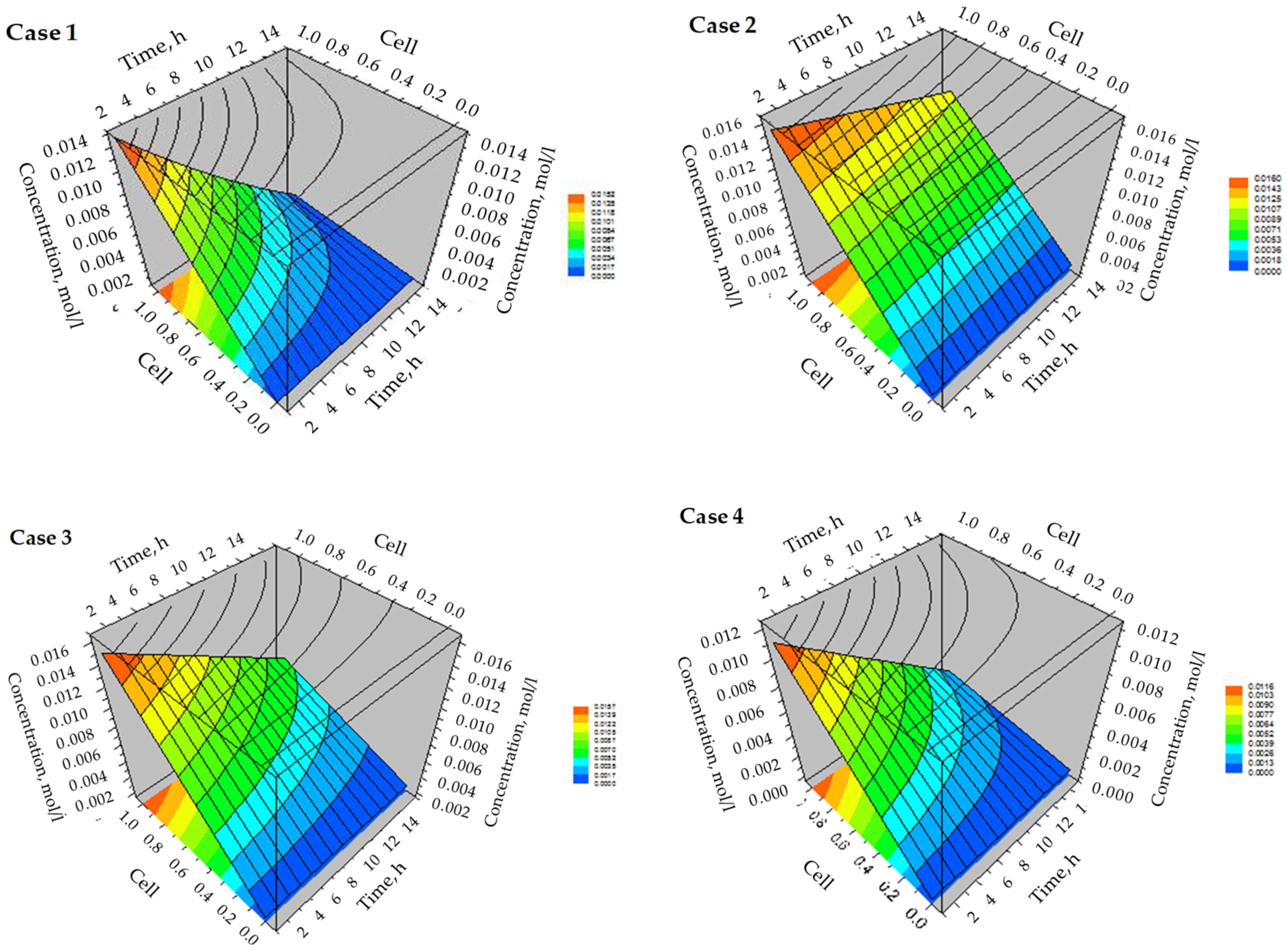
3.3. Simulation of Dynamic Thermal-Swing Adsorption in the CFAZ-CO2 System

The model studies of dynamic thermal-swing adsorption of CO2 onto CFAZ were performed using ProSim DAC dynamic simulation software (ProSim SA, France) based on the mass and enthalpy balances. The input data delivered by the CFAZ characterization and experimental CO2 adsorption studies are summarized in Table 3.
The process flow sheet is presented in Figure 7. The configuration includes a CO2/N2 inlet flow to the adsorption column, a N2 flow for thermal regeneration and an outlet flows from the adsorption and regeneration. The simulations were made on a lengthwise flow adsorption column with specified dimensions equal to the adsorbent bed used for the laboratory experiment.
The type and the column dimensions are illustrated in Figure 8. The description of the dynamic adsorption model is based on the partial mass balance between the concentration of CO2 in the gas phase flowing through the adsorbent bed and the amount of CO2 retained in the solid phase, expressed by the following equation [31,32]:
D 2 C i z 2 + v C i z + C i t + 1 ε ε ρ p q i t = 0
where: qi is the adsorbed CO2 concentration, mol/kg; Ci is CO2 concentration in the gas phase, mol/m3; ε–free volume rate in the adsorbent bed; ρp–bulk adsorbent density, kg/m3; D–axial mass dispersion coefficient, m2/s; z-column length, m; and v–superficial velocity, m/s.
To calculate the adsorption dynamics in the CO2-CFAZ system, the mass transfer can be divided into zones, as schematically presented in Figure 9. The adsorption and desorption kinetics are described by applying the Linear Driving Force model (LDF), which is widely applied to different adsorption systems [33]. The LDF model represents the mass transfer rate, assuming a global mass transfer coefficient K, counting the difference between the actual adsorbed amount of CO2 qi and the potentially adsorbed quantity qeq at equilibrium:
q i t = K q e q q i
which can be applied for the description of the combined mass transfer in gas and solid phases, as follows:
1 K = ρ g V M q i K e x a p y + r p 5 D g a p
where: K–global mass transfer coefficient, s−1; VM is the gas molar volume, m3/mol; ρg is the gas phase density, kg/m3; qi is the adsorbed quantity in the solid phase, mol/kg; ap is the surface/volume ratio of the adsorbent particle; y is the molar fraction; Kex is the external mass transfer coefficient, s−1; rp is the adsorbent particle radius, m; and Dg is the global intra-particular diffusivity, m2/s.
Simultaneously, mass transfer resistance phenomena occur, which have to be taken into account for both the gas and solid phases in the model descriptions. The partial mass transfer resistance in the gas phase is described by the following equation:
1 ε ρ p q i t = K f i S p C i C i *
where: Kfi-mass transfer coefficient in the gas phase, m/s; Sp-Specific surface per bed volume unit, m2/m3; ε–free volume ratio in the adsorbent bed; Ci–gas component partial concentration, mol/m3; C i * -gas phase partial concentration at the interface (mol/m3); and ρp-adsorbent particle density, kg/m3.
The partial resistance to the mass transfer in the solid phase is calculated by
q i t = K p i q i * q i
where: q i * is the gas content at the solid interface, mol/kg; and Kpi is the mass transfer coefficient of the gas in the solid, m/s.
Kfi and Kpi were calculated by ProSim DAC software.
The dynamic adsorption was done at a slightly increased pressure of 2 atm and at an ambient temperature of 24 °C. Therefore, the ideal thermodynamic profile was selected for the thermodynamic calculations.
For the adsorption modeling, the enthalpy balance was taken into account, considering the heat exchange in the CFAZ-CO2 adsorption system and the heat exchange between the gas and the column walls. In the enthalpy balance for the adsorbent bed, the accumulated heat in the solid phase, the accumulated heat in the adsorbed phase and the heat exchanged between the solid and gas phases were considered by applying the Satterfield equation [33]. The heat transfer between the gas and the column wall is estimated using the Leva correlations [33].
The experimental and model breakthrough curves are plotted in Figure 6. The distribution profile of CO2 concentration in a discretization cell of the adsorption bed relative to the process dynamics is presented in Figure 10. The concentration distribution reveals strong adsorption across the length of the discretization cell.
The desorption process is simulated by passing a stream of nitrogen through the adsorption column at a temperature of 60 °C after 15 and 30 min from the beginning of the adsorption process. The simulation studies show an intensive desorption process at the studied temperature, and with increasing the flow rate of the regeneration flow desorption is accelerated.
The breakthrough curves of the desorption simulation are presented in Figure 11.
The validated model was applied for the simulation of pilot columns for carbon capture based on TSA process with CFAZ adsorbent. The selected column dimensions (diameter D, length L and volume Vcol), and the adsorbent quantity (mCFAZ) and bed volume (VCFAZ) are summarized in Table 4. The computation cases were performed for 1000 m3/h of flue gas containing N2 and CO2 in a volume ratio of 90/10 vol%/vol%. The adsorbate temperature was kept constant of 24 °C in all simulation experiments, while two adsorbent pressures were studied. The simulated breakthrough curves for each studied case are plotted in Figure 12.
The obtained results reveal the influence of the D/L ratio of the adsorption column at an equal mass of the adsorbent on the adsorbed amount of CO2 (qCO2) as the best retaining ability is calculated in Case 2. This indicates that, for practical applications, optimization of this parameter is required. With the same column size, the decrease in working pressure significantly reduces the adsorption capacity, as found in the comparison of Cases 3 and 4. Simulations show a complete retention of CO2 from a gas mixture, close in volume content of CO2 to the real concentrations in the flue gases during the combustion of fossil fuels. Zero CO2 concentrations were found at the outlet of the adsorption column for about 30 min, after which the concentration increased sharply, reaching full saturation of the column. The adsorption capacity of CFAZ for CO2 capture calculated by the simulation experiment reaches about 3 mol/kg adsorbent, which is a value that is comparable to that obtained from model studies of pilot adsorption columns filled with activated carbon [34]. In zeolite 13X model studies, CO2 retention capacity values of about 8 mol/kg are expected [34], but this does not take into account the textural properties of the material and the adsorption dynamics. Zeolite 13X is predominantly a microporous material, while CFAZ has a mixed micro-mesoporous structure, therefore accelerated adsorption/desorption in the coal ash derived adsorbent is expected compared to pure zeolite [35].
The 3D distribution of the CO2 concentration in a discretization cell of the adsorption bed for each studied case of a pilot plant simulation is plotted in Figure 13. The highest saturation of the adsorbent is found in the depth of the discretization cells. As the adsorption capacity of the layer in the column increases, due to the optimization of the geometric parameters, the adsorption front shifts towards the beginning of the cell. As the pressure increases during the adsorption mode, the CO2 retention capacity is expected to increase significantly when CFAZ is used as an adsorbent due to the capillary condensation effects typical for mesoporous materials [36]. Studies at elevated pressures of 5.5 MPa reveal more than a twofold increase in the adsorption capacity of CFAZ toward CO2. The applicability of the LDF model for a reliable description of the adsorption of CO2 on zeolite 13X at supercritical pressures of 15 MPa has been reported in [37]. Model calculations at supercritical parameters show an adsorption capacity of 13X to CO2 of 7.5 mol/kg, which is a value that is comparable to that reported at pressures close to atmospheric [34,37].

4. Discussion

An excellent agreement was found between the experimental and model curves, indicating that the LDF model describes with high reliability the dynamic adsorption in the CO2-CFAZ system and can be applied in model calculations of adsorption columns with higher capacity. Simulation studies that have been previously performed describe the dynamic adsorption of CO2 on CFAZ obtained by magnetic homogenization of the reaction mixtures, which are characterized by a lower degree of zeolitization [21]. By them the application of the LDF model is also validated, but with a significant displacement in the mass transfer front. In the CFAZ synthesized by ultrasonically stimulated synthesis, an excellent overlap of the experimental and model breakthrough curves was found, which could be explained by the higher uniformity, the finer morphology and the larger surface to volume ratio of the adsorbent particles, which facilitates monolayer adsorption in close to atmospheric pressures. When comparing the breakthrough curves of CO2 adsorption on CFAZ, obtained by the two methods of homogenization, it was found that the time after which 50% of the initial concentration of the adsorbate in the effluent (T1/2) was registered is about 20 min for those synthesized by magnetic homogenization and 3.6 min for the ultrasonically treated samples, while the dynamic adsorption capacities are 99 mg/g and 123 mg/g, correspondingly. These results confirm the faster kinetics of the adsorption process in the ultrasonic CFAZ, and hence the better correlation with the LDF model
The main drawback for the widespread implementation of PCC technologies in industrial scales is the high energy consumption from the regeneration of the sorbent, which usually requires temperatures of 120–160 °C. Due to the physical nature of the process of retention of CO2 molecules and the mixed micro-mesoporous structure of CFAZ their regeneration takes place at much lower temperatures of the order of 60 °C. The high adsorption capacity to CO2, the favorable regeneration, the low cost and the beneficial ecological effect of the waste recovery, instead of its disposal, define CFAZ as promising adsorbents for carbon capture technologies. The low regeneration temperature of CO2 loaded CFAZ was confirmed by experimental thermogravimetric studies, of which a degree of regeneration over 90% has been established at temperatures of 60 °C [21].

5. Conclusions

As a result of the performed simulation studies of the dynamic adsorption and regeneration in the CO2-coal fly ash zeolite system using ProSim DAC software the Linear Driving Force model is validated, which describes with high reliability the processes kinetics. Experimental results from structural, morphological and surface studies of the samples and laboratory tests from the equilibrium and dynamic CO2 adsorption are applied as input data for the model studies. A higher correlation of the LDF model was found in the description of the dynamic processes of CO2 adsorption from coal ash zeolites obtained by ultrasonic-assisted synthesis than in those synthesized by magnetic homogenization from previous studies. This observation was explained by the greater uniformity and the higher surface to volume ratio at the sonicated CFAZ, which contribute to the monolayer adsorption of CO2 at pressures close to the atmospheric. Coal ash zeolites are promising adsorbents for carbon capture and utilization technologies and represent an economically viable technological solution with high environmental benefits. With the application of the LDF model, carbon capture installations with CFAZ adsorption media can be scaled for pilot studies.

Author Contributions

Conceptualization, S.B.; methodology, D.Z.-F.; software, I.M.; validation, D.Z.-F. and I.M.; formal analysis, D.Z.-F.; investigation, D.Z.-F. and I.M.; resources, S.B.; data curation, D.Z.-F.; writing—original draft preparation, S.B.; writing—review and editing, S.B.; visualization, D.Z.-F. and I.M.; supervision, S.B.; project administration, S.B.; funding acquisition, S.B. All authors have read and agreed to the published version of the manuscript.

Funding

This research and the APC were funded by the Bulgarian National Science Fund (BNSF) under the Grant DN 17/18 (12 December 2017).

Acknowledgments

The financial support of the Bulgarian National Science Fund (BNSF) under the Project DN 17/18 (12 December 2017) is highly appreciated.

Conflicts of Interest

The authors declare no conflict of interest.

References

  1. International Energy Agency: IEA. Available online: https://www.iea.org (accessed on 13 November 2021).
  2. United Nations Climate Change. Available online: https://www.unfccc.int (accessed on 13 November 2021).
  3. Herzog, H.J. Peer reviewed: What future for carbon capture and sequestration? New technologies could reduce carbon dioxide emissions to the atmosphere while still allowing the use of fossil fuels. Environ. Sci. Technol. 2001, 35, 148A–153A. [Google Scholar] [CrossRef] [PubMed] [Green Version]
  4. Liang, Z.-W.; Rongwong, W.; Liu, H.; Fu, K.; Gao, H.; Cao, F.; Zhang, R.; Sema, T.; Henni, A.; Sumon, K.; et al. Recent progress and new developments in post-combustion carbon-capture technology with amine based solvents. Int. J. Greenh. Gas Con. 2015, 40, 26–54. [Google Scholar] [CrossRef] [Green Version]
  5. Plaza, J.M.; Van Wagenera, D.; Rochellea, G.T. Modeling CO2 capture with aqueous monoethanolamine. Energ. Proc. 2009, 1, 1171–1178. [Google Scholar] [CrossRef] [Green Version]
  6. Kárászová, M.; Zach, B.; Petrusová, Z.; Červenka, V.; Bobák, M.; Šyc, M.; Izák, P. Post-combustion carbon capture by membrane separation. Review. Sep. Purif. Technol. 2020, 238, 116448. [Google Scholar] [CrossRef]
  7. Samanta, A.; Zhao, A.; Shimizu, G.K.H.; Sarkar, P.; Gupta, R. Post-combustion CO2 capture using solid sorbents: A review. Ind. Eng. Chem. Res. 2012, 51, 1438–1463. [Google Scholar] [CrossRef]
  8. Berger, A.H.; Bhown, A.S. Optimizing solid sorbents for CO2 capture. Energ. Proc. 2013, 37, 25–32. [Google Scholar] [CrossRef] [Green Version]
  9. Hollman, G.G.; Steenbruggen, G.; Jurkovičová, M.J. A two-step process for the synthesis of zeolites from coal fly ash. Fuel 1999, 78, 1225–1230. [Google Scholar] [CrossRef]
  10. Boycheva, S.; Behunová, D.; Václavíková, M. Smart- and zero-energy utilization of coal ash from thermal power plants in the context of circular economy and related to soil recovery. J. Environ. Eng. 2020, 146, 04020081. [Google Scholar]
  11. Yao, Z.T.; Ji, X.S.; Sarker, P.K.; Tang, J.H.; Ge, L.Q.; Xia, M.S.; Xi, Y.Q. A comprehensive review on the applications of coal fly ash. Earth-Sci. Rev. 2015, 141, 105–121. [Google Scholar] [CrossRef] [Green Version]
  12. Mendoza, E.Y.M.; Santos, A.S.; López, E.V.; Drozd, V.; Durygin, A.; Chen, J.; Saxena, S.K. Iron oxides as efficient sorbents for CO2 capture. J. Mat. Res. Technol. 2019, 8, 2944–2956, doiorg/101016/jjmrt201905002. [Google Scholar] [CrossRef]
  13. Boycheva, S.; Zgureva, D.; Lazarova, H.; Popova, M. Comparative studies of carbon capture onto coal fly ash zeolites Na-X and Na–Ca-X. Chemosphere 2021, 271, 129505. [Google Scholar] [CrossRef]
  14. Zhao, R.; Liu, L.; Zhao, L.; Deng, S.; Li, S.; Zhang, Y. A comprehensive performance evaluation of temperature swing adsorption for post-combustion carbon dioxide capture. Renew. Sustain. Energ. Rev. 2019, 114, 109285. [Google Scholar] [CrossRef]
  15. Chue, K.T.; Kim, J.N.; Yoo, Y.J.; Cho, S.H.; Yang, R.T. Comparison of activated carbon and zeolite 13X for CO2 recovery from flue gas by Pressure Swing Adsorption. Ind. Eng. Chem. Res. 1995, 34, 591–598. [Google Scholar] [CrossRef]
  16. Azarabadi, H.; Lackner, K.S. A sorbent-focused techno-economic analysis of direct air capture. Appl. Energ. 2019, 250, 959–975. [Google Scholar] [CrossRef]
  17. Baiker, A. Utilization of carbon dioxide in heterogeneous catalytic synthesis. Appl. Organometal. Chem. 2000, 14, 751–762, doiorg/101002/1099. [Google Scholar] [CrossRef]
  18. Marchese, M.; Buffo, G.; Santarelli, M.; Lanzini, A. CO2 from direct air capture as carbon feedstock for Fischer-Tropsch chemicals and fuels: Energy and economic analysis. J. CO2 Utiliz. 2021, 46, 101487. [Google Scholar] [CrossRef]
  19. Popova, M.; Boycheva, S.; Lazarova, H.; Zgureva, D.; Lázár, K.; Szegedi, Á. VOC oxidation and CO2 adsorption on dual adsorption/catalytic system based on fly ash zeolites. Catal. Tod. 2020, 357, 518–525. [Google Scholar] [CrossRef]
  20. Boycheva, S.; Marinov, I.; Miteva, S.; Zgureva, D. Conversion of coal fly ash into nanozeolite Na-X by applying ultrasound assisted hydrothermal and fusion-hydrothermal alkaline activation. Sustain. Chem. Pharm. 2020, 15, 100217. [Google Scholar] [CrossRef]
  21. Zgureva, D.; Boycheva, S. Experimental and model investigations of CO2 adsorption onto fly ash zeolite surface in dynamic conditions. Sustain. Chem. Pharm. 2020, 15, 100222. [Google Scholar] [CrossRef]
  22. International Zeolite Association (IZA). Available online: https://www.iza-online.org (accessed on 30 November 2021).
  23. Uppili, S.; Thomas, K.J.; Crompton, E.M.; Ramamurthy, V. Probing zeolites with organic molecules:  supercages of X and Y zeolites are superpolar. Langmuir 2000, 16, 265–274. [Google Scholar] [CrossRef]
  24. Osatiashtiani, A.; Puertolas, B.; Oliveira, C.C.S.; Manayil, J.C.; Barbero, B.; Isaacs, M.; Michailof, C.; Heracleous, E.; Pérez-Ramírez, J.; Lee, A.F.; et al. On the influence of Si:Al ratio and hierarchical porosity of FAU zeolites in solid acid catalysed esterification pretreatment of bio-oil. Biomass Conv. Bioref. 2017, 7, 331–342. [Google Scholar] [CrossRef] [Green Version]
  25. Nikolakis, V.; Xomeritakis, G.; Abibi, A.; Dickson, M.; Tsapatsis, M.; Vlachos, D.G. Growth of a faujasite-type zeolite membrane and its application in the separation of saturated/unsaturated hydrocarbon mixtures. J. Membr. Sci. 2001, 184, 209–219. [Google Scholar] [CrossRef]
  26. Julbe, A.; Drobek, M. Zeolite X: Type. In Encyclopedia of Membranes; Drioli, E., Giorno, L., Eds.; Springer: Berlin/Heidelberg, Germany, 2014. [Google Scholar] [CrossRef]
  27. Su, F.; Lu, C. CO2 capture from gas stream by zeolite 13X using a dual-column temperature/vacuum swing adsorption. Energy Environ. Sci. 2012, 5, 9021–9027. [Google Scholar] [CrossRef]
  28. Thommes, M.; Kaneko, K.; Neimark, A.V.; Olivier, J.P.; Rodriguez-Reinoso, F.; Rouquerol, J.; Sing, K.S.W. Physisorption of gases, with special reference to the evaluation of surface area and pore sizedistribution (IUPAC Technical Report). Pure Appl. Chem. 2015, 87, 1051–1069. [Google Scholar] [CrossRef] [Green Version]
  29. Bardestani, R.; Patience, G.S.; Kaliaguine, S. Experimental methods in chemical engineering: Specific surface area and pore size distribution measurements—BET, BJH, and DFT. Can. J. Chem. Eng. 2019, 97, 2781–2791. [Google Scholar] [CrossRef]
  30. Bolis, V. Fundamentals in adsorption at the solid-gas interface. Concepts and thermodynamic. In Calorimetry and Thermal Methods in Catalysis; Auroux, A., Ed.; Springer Series in Materials Science; Springer: Berlin/Heidelberg, Germany, 2013; Volume 154, pp. 3–50. [Google Scholar]
  31. Ruthven, D.M. Adsorption (Chemical Engineering). In Encyclopedia of Physical Science and Technology, 3rd ed.; Meyers, R.A., Ed.; Academic Press: Cambridge, MA, USA, 2003; pp. 251–271. [Google Scholar] [CrossRef]
  32. Chou, C.-T.; Wu, B.-C.; Wu, T.-L.; Yang, H.-S.; Shen, C.-H. Concentrating high purity CO2 from syngas after oxy-fuel combustion by pressure swing adsorption process. Comp. Aided Chem. Eng. 2018, 43, 1425–1431 doiorg/101016/B978. [Google Scholar]
  33. Perry, R.H.; Green, D.W.; Maloney, J.O. Perry’s Chemical Engineers Handbook, 7th ed.; McGraw-Hill: New York, NY, USA, 2007. [Google Scholar]
  34. Herraiz, L.; Palfi, E.; Sánchez, E.F.; Mathieu, L. Rotary Adsorption: Selective recycling of CO2 in combined cycle gas turbine power plants. Front. Energ. Res. 2020, 8, 308. [Google Scholar] [CrossRef]
  35. Kalvachev, Y.; Zgureva, D.; Boycheva, S.; Barbov, B.; Petrova, N. Synthesis of carbon dioxide adsorbents by zeolitization of fly ash. J. Therm. Anal. Cal. 2016, 124, 101–106. [Google Scholar] [CrossRef]
  36. Boycheva, S.; Zgureva, D. Studies on the CO2 adsorption onto coal fly ash zeolites at elevated Pressures. In Proceedings of the 17th International Conference on Environmental Science and Technology (CEST 2021), Athens, Greece, 1–4 September 2021. [Google Scholar]
  37. Kareem, F.A.A.; Shariff, A.M.; Ullah, S.; Dreisbach, F.; Keong, L.K.; Mellon, N.; Garg, S. Experimental measurements and modeling of supercritical CO2 adsorption on 13X and 5A zeolites. J. Nat. Gas Sci. Eng. 2018, 50, 115–127, doiorg/101016/jjngse201711016. [Google Scholar] [CrossRef]
Figure 1. Stages in the development and testing of adsorbents for industrial applications.
Energies 14 08279 g001
Figure 2. XRD studies of CFAZ.
Energies 14 08279 g002
Figure 3. SEM images of CFAZ.
Energies 14 08279 g003
Figure 4. Surface studies of CFAZ: (a) N2-adsorption/desorption isotherms; (b) BJH-pore size distribution function.
Energies 14 08279 g004
Figure 5. Experimental and Langmuir model isotherms of CO2 adsorption onto CFAZ.
Energies 14 08279 g005
Figure 6. Experimental and model breakthrough curves of CO2 adsorption onto CFAZ.
Energies 14 08279 g006
Figure 7. Process flow-chart built in the ProSim DAC simulation software.
Energies 14 08279 g007
Figure 8. Lengthwise flow adsorption column for the numerical studies.
Energies 14 08279 g008
Figure 9. Mass transfer zones in a simulation model of dynamic adsorption in the CO2-CFAZ system, where C i *   a n d   q i * are the gas phase partial concentration and the gas content in solid at the gas-solid interface, correspondingly.
Energies 14 08279 g009
Figure 10. 3D concentration distribution of CO2 in a discretization cell of the adsorption bed.
Energies 14 08279 g010
Figure 11. Breakthrough curves of the desorption of CO2 loaded CFAZ simulated by ProSim DAC software.
Energies 14 08279 g011
Figure 12. Break through adsorption curves of carbon caption in pilot adsorption columns with CFAZ as an adsorbent.
Energies 14 08279 g012
Figure 13. 3D concentration distribution of CO2 in a discretization cell of the adsorption bed for the cases of a pilot plant capture unit.
Energies 14 08279 g013
Table 1. Surface parameters of CFAZ studied as an adsorbent of CO2.
SampleSBET,
m2/g
Smicro,
m2/g
Sextern,
m2/g
Vmicro,
cm3/g
Vmeso,
cm3/g
Vtotal,
cm3/g
dmicro,
Å
dmeso, Å
CFAZ4863341660.130.170.311442
Table 2. Langmuir model parameters of CO2 adsorption onto CFAZ.
Sampleqm,
mol/kg
K,
atm−1
K,
kPa−1
R2Cads, mmol/g
(100 kPa)
Cads,dyn,
mmol/g
CFAZ3.097216.530.12440.99983.0262.8
Table 3. Input parameters for dynamic simulation of TSA process in the CFAZ-CO2 system.
GroupParameterSymbolDimensionValue
Adsorption columnColumn typeLengthwise flow column
Diameter of the adsorption columnDcm0.8
Length of the adsorption columnLcm11.15
Bed void ratioεm3/m30.73
Initial temperatureTin°C24
Initial pressurePinatm2
Temperature of the wallTwall°C24
AdsorbentDensity of the materialρkg/m30.8
Specific heat of the solidcpJ/kg·K950
Particle diameterdpmm0.002
Particle surface/volume ratioRm2/m3300,000
Adsorption isotherm correlationLangmuir
Model parameter 1qimol/kg3.0537
Model parameter 2Katm−121.53156
AdsorbateVolume flow rateQadsL/min0.03
Gas mixture volume ratioN2/CO2vol%/vol%90/10
Adsorbate pressurePadsatm2
Adsorbate temperatureTads°C24
Number of discretization cellsz-10
Simulation timets3600
Table 4. Parameters for computation of pilot plant adsorption columns for CO2 capture by TSA onto CFAZ.
Case NumberD,
m
L,
m
Vcol,
m3
εVCFAZ,
m3
mCFAZ,
kg
Pads,
atm
qCO2,
kmol
11.01310.420.5704.48358548.04
21.558.840.4934.48358449.64
32.026.280.2874.48358449.19
42.026.280.2874.48358438.14
Publisher’s Note: MDPI stays neutral with regard to jurisdictional claims in published maps and institutional affiliations.

