Article

Activities in Divertor Reflector and Linear Plates Using WCLL and HCPB Breeding Blanket Concepts

by
Simona Breidokaite
* and
Gediminas Stankunas
Laboratory of Nuclear Installation Safety, Lithuanian Energy Institute, Breslaujos g. 3, LT-44403 Kaunas, Lithuania
*
Author to whom correspondence should be addressed.
Energies 2021, 14(24), 8305; https://doi.org/10.3390/en14248305
Submission received: 15 September 2021 / Revised: 30 November 2021 / Accepted: 7 December 2021 / Published: 9 December 2021

Abstract

:
In fusion devices, such as European Demonstration Fusion Power Reactor (EU DEMO), primary neutrons can cause material activation due to the interaction between the source particles and the targeting material. Subsequently, the reactor’s inner components become activated. For safety and safe performance purposes, it is necessary to evaluate neutron-induced activities. Activities results from divertor reflector and liner plates are presented in this work. The purpose of liner shielding plates is to protect the vacuum vessel and magnet coils from neutrons. As for reflector plates, the function is to shield the cooling components under plasma-facing components from alpha particles, thermal effects, and impurities. Plates are made of Eurofer with a 3 mm layer of tungsten, while the water is used for cooling purposes. The calculations were performed using two EU DEMO MCNP (Monte Carlo N-Particles) models with different breeding blanket configurations: helium-cooled pebble bed (HCPB) and water-cooled lithium lead (WCLL). The TENDL–2017 nuclear data library has been used for activation reactions cross-sections and nuclear reactions. Activation calculations were performed using the FISPACT-II code at the end of irradiation for cooling times of 0 s–1000 years. Radionuclide analysis of divertor liner and reflector plates is also presented in this paper. The main radionuclides, with at least 1% contribution to the total value of activation characteristics, were identified for the previously mentioned cooling times.

1. Introduction

More and more governments are investing in “green technologies,” renewable energy sources, and the reduction of fossil fuel usage [1]. One of the alternatives is nuclear fusion power plants because, while operating, they will not produce air pollution or carbon dioxide. Different to fission fuel, lithium mining is a more straightforward process than uranium mining and does not require that much energy, and no risk of nuclear accidents such as Chernobyl. However, there are still some radioactive reactor components that must be evaluated.
In well-known fusion reactions, two light elements are combined to form a single heavier nucleus and release subatomic particles (neutrons and protons) with large amounts of energy in the form. Positively charged nuclei can be brought together so that a fusion reaction takes place, at which point sufficient energy must be provided to overcome the electric repulsion forces. That can be achieved just in plasma—a state of matter which is a hot, charged gas made of positive ions and free-moving electrons, and it has unique properties distinct from solids, liquids, and gases [2]. Francis William Aston’s invention, the mass spectrometer, led to the realization that nuclear fusion could be a potential source of energy. In 1920, he measured the helium-4 nucleus and hydrogen nucleus, and determined that helium mass is lower than the combined mass of its constituents [3]. Twenty years later, Mark Oliphant discovered tritium nuclei by bombarding deuterium nuclei with deuterium [2].
The energy radiated during nuclear fusion has two significant advantages over the energy released during nuclear fission:
  • Safe. Safety problems in a nuclear fission reactor, such as transient power, supercritical, or other accidental uncontrolled radioactive fission, will not occur in this type of reactor. For fusion reactors to operate stably, plasma must meet stringent conditions. If those conditions are not maintained, the fusion reaction will stop spontaneously, ensuring safety. The residual heat in the fusion reactor is mainly due to the fission of activated materials during the shutdown. Thus, the residual heat in the fusion reactor is much lower and more accessible to remove than in the fission reactor, where the heat is dissipated using spent fuel, leading to significant accidents [4];
  • No long-lasting or high-level waste. During the decommissioning of a fusion reactor, the radioactive waste consists mainly of tritium and activation products such as structural materials, breeding blankets, and cooling materials irradiated with neutrons. In addition, the half-life of tritium is short (about 12.3 years), and the energy of the electrons emitted by beta decay is low (average 5.68 keV). Thus, the tritium does not cause external radiation exposure. Even if there is a leak, there will be no long-term radioactivity at that site [5].
According to the European Fusion Roadmap, nuclear fusion will not be realized by 2050 [6]. Complaints of fusion mainly occur because it is challenging to create a fusion reactor on Earth. It can be the solution to current energy problems, but it requires a lot of time, and it requires a large amount of energy to maintain the main parameters. One main argument why fusion reactors should not be developed is that they cost too much, and that amount of money could be divided into the development of other renewable technology [7]. Still, it can altogether contribute to the vitality blend within the long term and basically supply electricity or warmth in highly populated areas [6].
The three main facilities mentioned on the fusion roadmap are International Thermonuclear Experimental Reactor (ITER), European Demonstration Fusion Power Reactor (EU DEMO,) and International Fusion Materials Irradiation Facility DEMO Oriented Neutron Source (IFMIF-DONES) [8]. ITER should demonstrate that fusion is feasible. The next step will be to have a self-sufficient fuel cycle, and first-time electricity will be produced from fusion. IFMIF-DONES is needed to test and validate materials for DEMO and the fusion power plants [8].
The roadmap addresses three separate periods with distinct main objectives.
The three stages to design fusion power plants:
  • Near-term: Construction, research and development of ITER, IFMIF-DONES, and DEMO conceptual design, and research to determine whether stellarator is a cheaper, easier way to reach fusion;
  • Medium-term: Utilize ITER to its full potential to construct the best version of DEMO and possible further development of the stellarator concept;
  • Long-term: Using results from ITER performance, finalized design of DEMO and its construction. At this point, there will be qualified long-life materials for DEMO and power plants [8].
These three steps provide a realistic timescale when magnetic confined fusion demonstrates commercial electricity production. The fusion roadmap forms a reasonable basis for the European fusion program [8].

2. EU DEMO Divertor

The EU DEMO reactor will be the first of this kind and the successor of ITER. DEMO is the objective of the EUROfusion Power Plant Physics and Technology (PPPT). The EU DEMO will be the last researched tokamak reactor before a commercial fusion power plant. It can produce 25 times more energy than it consumes, operating with a closed fuel cycle [9]. The five main EU DEMO goals are:
  • Convert fusion heat energy to electricity, approximately 500 MWe;
  • Achieve tritium self-sufficiency;
  • Operate for at least several years at full power;
  • Produce no long-term radioactive waste; and
  • Lead the development of fusion power plants [10].
The EU DEMO design is being developed, taking into account lessons learned from Generation IV fission reactors and ITER [11]. There are many differences: pulse length, required diagnostics, cooling system optimized for electricity generation efficiency, and fewer licensing constraints [9]. Furthermore, different breeding blanket, divertor, heating, current drive concepts, operation duration, and plasma operation scenarios are considered. DEMO has added several other plant systems. For example, the power conversion system (PCS) and tritium extraction system (TES). PCS is required to convert heat to electricity. It consists of an intermediate storage system, a steam turbine, and an electric generator. Because present steam turbines cannot cope with the pulsed plasma power of DEMO in the current layout phase, the intermediate storage system is included. TES is needed as a sufficient system for self-sufficient tritium extraction from breeding blankets. Currently, two options are under development: lithium lead or helium purge gas to deliver the tritium to its extraction system. [12]. These technologies and physics issues should be taken into account [11].
The EU DEMO divertor’s first design was introduced in 2014, and it was developed based on the ITER design [13]. In 2019, two MCNP (Monte Carlo N-Particles) models were reproduced: WCLL and HCPB Single Module Segment layered blankets, both with the new MCNP model of the divertor configuration (see Figure 1). The DEMO1 2017 [14] baseline divertor model was changed since the new breeding blanket and vacuum vessel (VV) conceptions were introduced. The difference in the dimensions, especially inboard, is considerable in the new configuration model, and new shielding components are introduced to cover diffusers. The toroidal dimensions of the 2018 configuration stayed the same (16 sectors have resulted in 48 divertor cassettes).
The main six divertor components are:
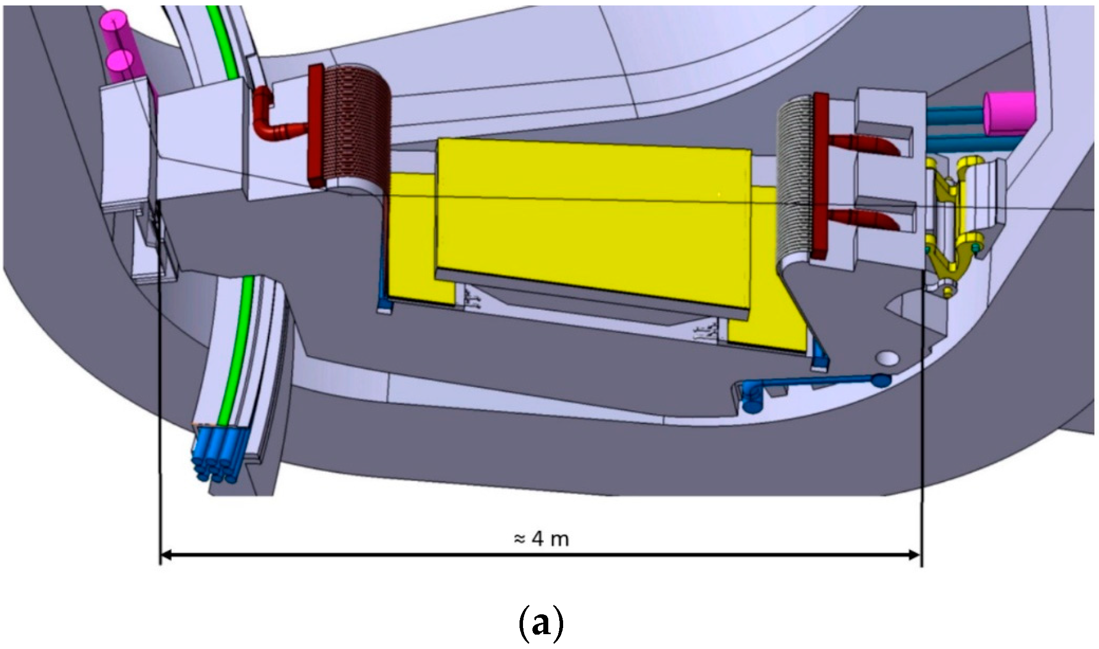
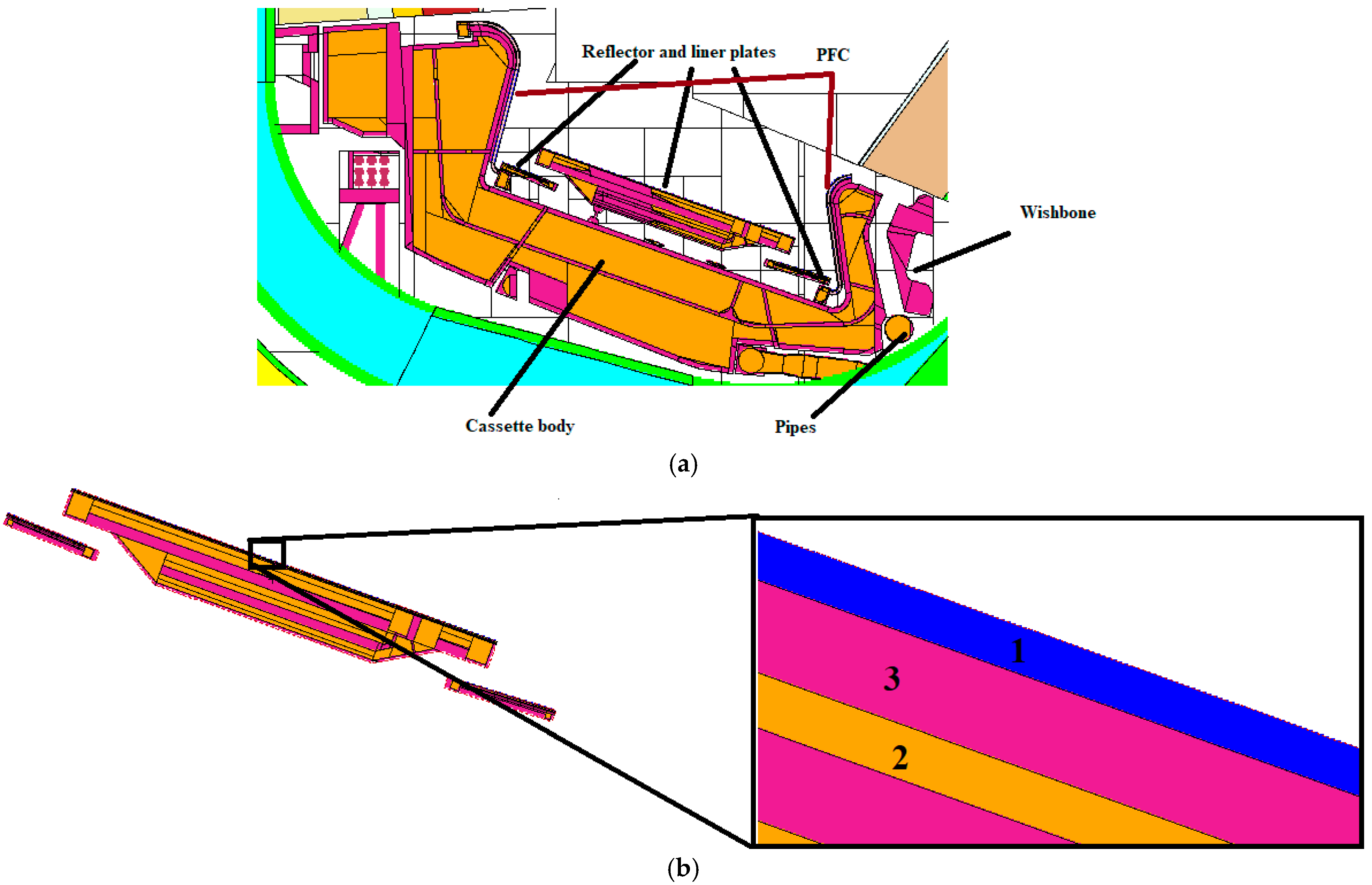
  • Vertical target or plasma-facing components (PFC): In one cassette, there are inner and outer parts. The height of the inner part is 0.76 m, and the height of the outer part is 0.65 m. The width of the targets is 1.07 and 0.82 for the outer and inner parts accordingly. One cassette has 78 plasma-facing units (PFU), 45 in the outer part and 33 PFUs in the inner part. The plasma facing unit is made out of tungsten monoblock. Tungsten is cooled by water flowing through CuCrZr pipes. The internal diameter of the pipe is 12 mm, and its width is 1.5 mm; 1 mm is reserved for the interlayer between the monoblock and the pipes [16].
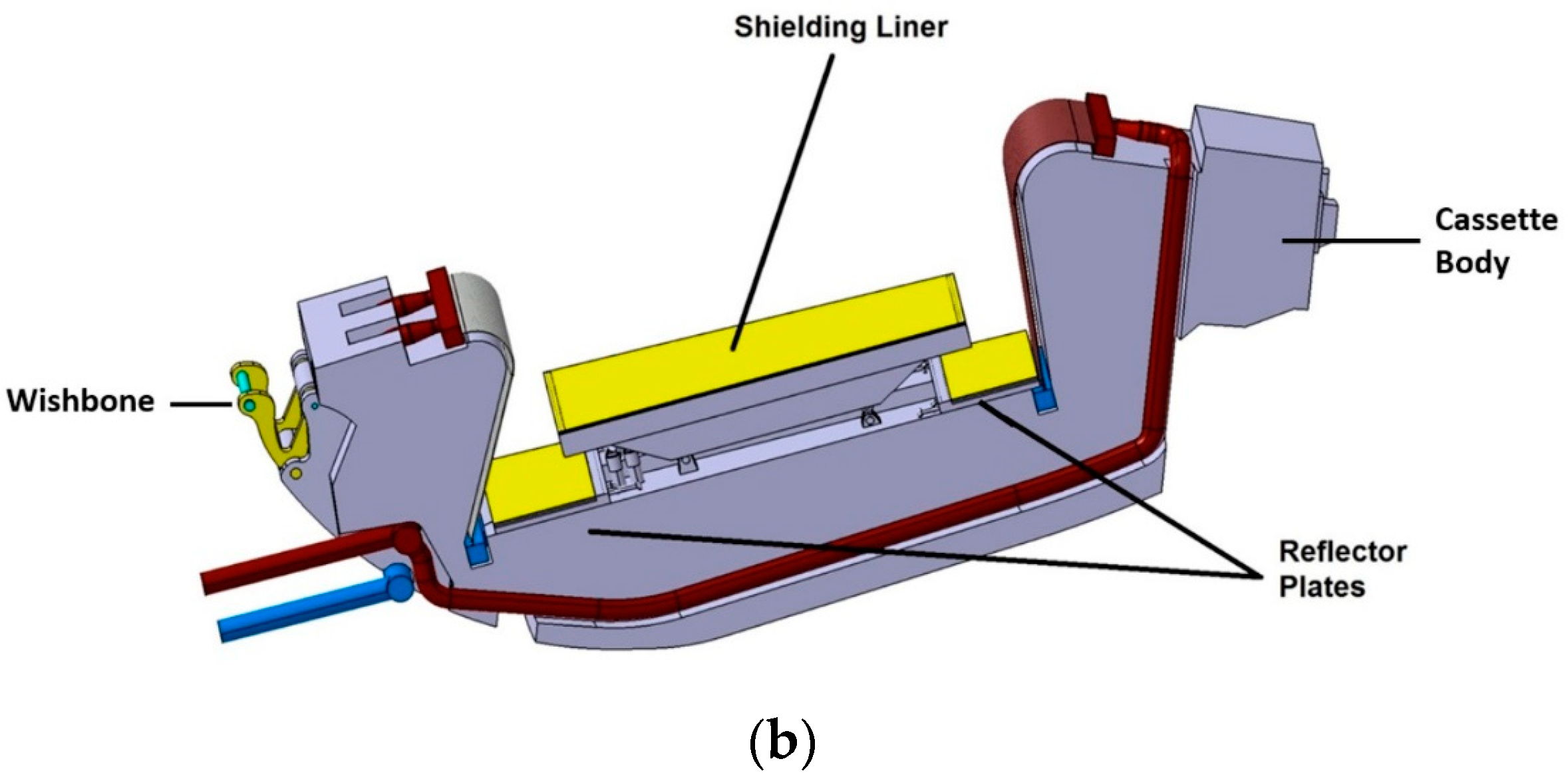
  • Shielding liner plate: The primary shielding liner plate function is to provide shielding for the VV and magnet coils from neutrons. The shielding liner plate is made of Eurofer and is cooled by the cassette cooling circuit. The plate is coated with 3 mm tungsten (see Figure 2). The purpose of the coating is to protect the stainless steel, in this work Eurofer, from erosion due to interaction with high energy neutrons. It is estimated that the shielding liner will be produced by using the vacuum plasma spraying technique to deposit a W (tungsten) layer on a small Eurofer surface.
  • Reflector plates: The primary function of the reflector plates is to provide thermal shielding for the components underneath, PFC manifolds and distributor cooling. It also protects those components from alpha particles and other impurities. Like the shielding liner plates, reflector plates are made of Eurofer with a 3 mm tungsten coating.
  • Divertor cassette body: Based on previous analyses baseline for the DEMO divertor, the new cassette body design is bigger in dimensions, especially at the inboard side [17,18,19]. The cassette body is made of Eurofer and is cooled with the same water circuit as liner and shielding plates [15].
  • Locking on vacuum vessel: “Nose” is the locking part of the divertor which attaches to the inboard vacuum vessel, while “whisbone” attaches to the outboard part. The NOSE concept was created to reduce the gap between the blanket and the cassette body in the final installation. The wishbone is a flexible component that fixes the cassette body via pin connections to the VV. It is made from Ti alloy, and the pins are made from Inconel alloy [20].
  • Cooling tubes and manifolds: The cooling circuit can be obtained from Figure 3, while dimensions are the same as in Figure 1a [15].
The construction of the EU DEMO should start in 2040 [20]. However, before building, neutron-induced activity in the components of the reactor must be evaluated. Material activation in the reactors is inevitable because neutrons will be used for tritium breeding and heat transfer. Of course, neutron material activation should be as low as possible. For that reason, different types of materials [21,22] and other concepts of the same in-vessel components are tested in various simulations [23].
In this work, activities in divertor liner and reflector plates are calculated using the helium-cooled pebble bed (HCPB) and water-cooled lithium lead (WCLL) breeding blanket concepts. Before activity calculations, neutron fluxes were calculated. The statistical error of the Monte Carlo calculation on the total neutron flux results for divertor cells was less than 10% when run for 1 × 10⁸ particle histories.

3. Materials and Calculational Methods

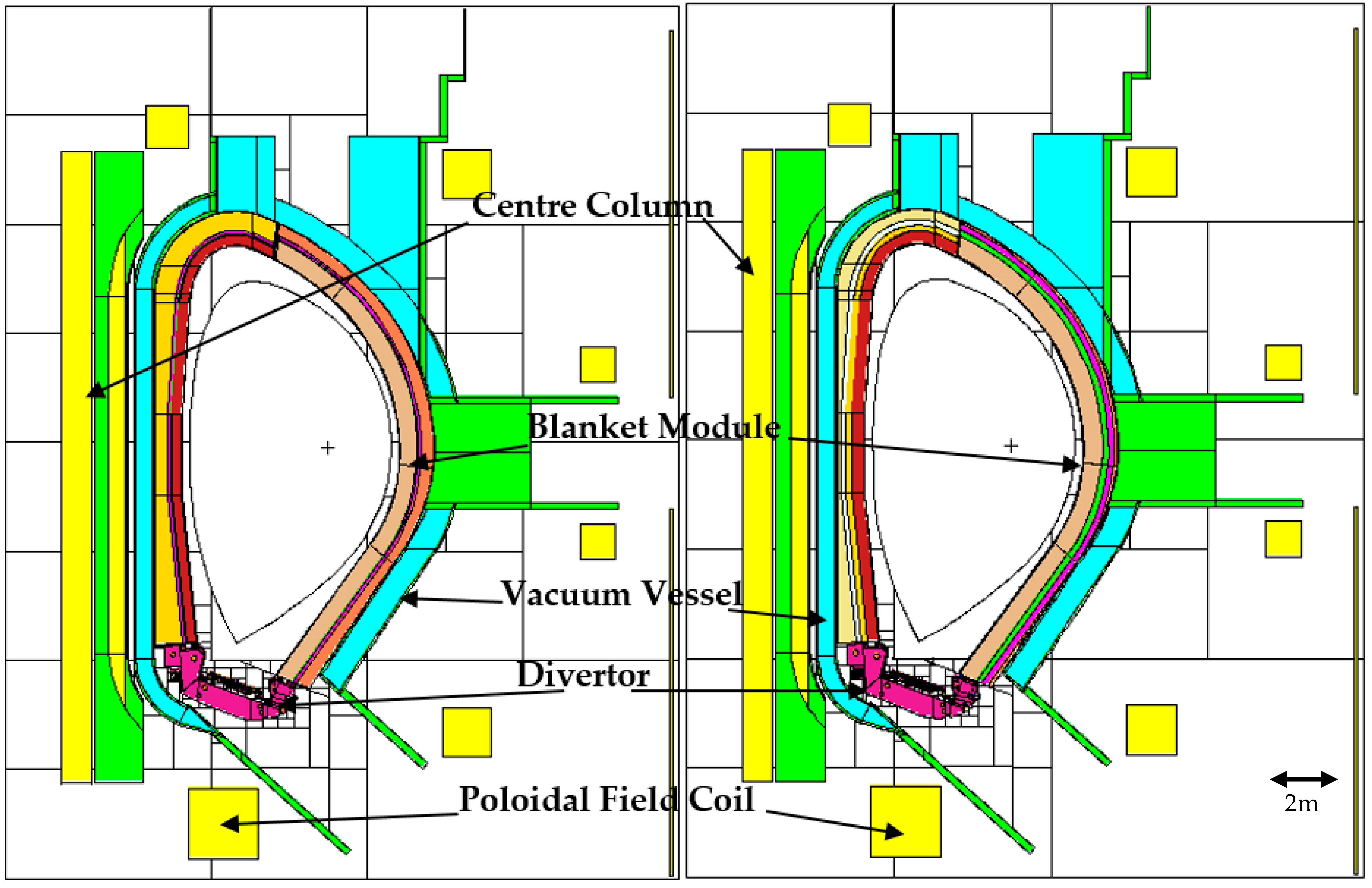
3.1. Geometrical DEMO Model and Materials

In the WCLL breeding blanket concept, breeding units are duplicated along the poloidal direction. Breeding units fill available space of the inboard (IB) and outboard (OB) of the DEMO tokamak. IB and OB structure differences are based on smaller inner radial thickness of the IB [16].
On the contrary, the HCPB breeding blanket concept is based on “sandwich” architecture [24], where there are pebble beds of lithium orthosilicate and beryllium between parallel cooling plates [25]. This model breeding blanket has 18 segments in IB, and OB has seven modules per segment [26].
The main difference in concepts is the tritium breeding material and neutron multipliers. Li4SiO4 ceramics and Li-Pb eutectic alloy are used as breeding material in HCPB and WCLL accordingly. Beryllium is used as a neutron multiplier in HCPB, while WCLL uses the same materials for tritium breeding [20].
To perform calculations, the extraction of the 11.25-degree toroidal sector from the full DEMO1 2017 (see Figure 4) geometry model was used [14]. The comparison was performed between HCPB and WCLL breeding blanket concepts in the DEMO1 model. The key parameters of the EU DEMO 2017 baseline are shown in Table 1. Breeding blankets are homogenized in the Monte Carlo N-Particle-6 (MCNP6) [27] model (more information on MCNP can be found in Section 3.3), since a fully detailed heterogeneous representation is unnecessary (see Figure 5 for details).
Liner and reflector plates are constructed from three types of material. Firstly, the 3mm layer of tungsten (99.9595% purity) is highly irradiated by neutrons but has a high melting point, sputtering resistance, and suitable thermal conductivity at room temperature [28]. The second material is Eurofer. After many experiments [21,29], it was chosen as one of the best candidates as a structural material. Eurofer’s material elemental composition consists of 88.698% iron, 9% chromium, 1.1% tungsten, 0.4% manganese, and other impurities. The last material is water, which is used for cooling purposes (see Table 2).

3.2. Irradiation Scenario

The irradiation scenario consists of 5.2 years of continuous operation at 30% of the nominal power and ten days with 48 pulses (4 h full power (1998 MW) operation and 1 h dwell time) at the end. This operation time was chosen as the longest irradiation time anticipated for a divertor cassette, resulting in the worst-case scenario. It causes the most significant values of activity.
The decay times considered for the calculation of the activity inventories and the decay heat are 1 s, 5 min, 30 min, 1 h, 3 h, 5 h, 10 h, 1 day, 3 days, 1 week, 2 weeks, 4 weeks, 8 weeks, 6 months, 1 year, 10 years, 50 years, 100 years, and 1000 years.

3.3. Modelling Tools

Monte Carlo methods are a broad class of computational algorithms that are based on repeated random selection. Monte Carlo-based programs are most commonly used to solve complex problems in evaluating and optimizing engineering, finance, statistics, mathematics, computer science, and the physical and life sciences [30].
When Monte Carlo-based codes are used, the only requirement is that the system could be described with probability density functions. Once the probability density function is defined, Monte Carlo modelling is performed by randomly taking values from the probability density function. A number of such simulations (stories) are completed, the desired result being the average value over the number of observations.
A feature that determines the widespread use of this method is the ability to solve complex problems that deterministic computer codes cannot model. Individual probabilistic events involving a process are simulated sequentially. Statistically, the probability distributions of these events are taken to describe the overall phenomenon. The statistical sampling process is based on selecting random numbers, analogous to dice gambling in a casino; hence, Monte Carlo.
In the case of particle transfer, the numerical experiment of the Monte Carlo method is realistic. This means that for each of the many source-generated particles, from the onset to the interaction, the processes are described by precise probabilistic density functions. The probability distribution is taken at random using mass/energy transfer data to determine the result of the particle interaction at each stage of the particle’s life [31].
In the nuclear fusion field, Monte Carlo method-based codes are used to solve the neutron transport equation. The most commonly used code is MCNP. It was created in 1977 at the Los Alamos National Laboratory (USA). MCNP was written using the FORTRAN and C programming languages. The code is currently under development. In the spring of 2018, the latest version of the software code, MCNP6.2, was introduced [32].
This software package can be used for heavy nuclear, proton, neutron, electron, and other particle transport calculations. MCNP is widely used in many fields such as fusion/fission reactor design calculations, radiation safety, dosimetry calculations, and medical physics calculations. Using this code, neutron interactions in the energy range of 10−11–150 MeV, and photon interactions in the energy range from 1 keV to 100 GeV, can be modelled [31].
Fispact-II is an inventory code that uses a nuclear library database to model activation–transmutation processes, time-dependent inventory, and radiation damage. The Fispact code was created and developed in the Culham Centre of Fusion Energy (CCFE) [33]. The code was designed for neutron, deuterium, and proton-induced activation calculations for materials in synthesis devices [34]. The main calculation steps, which the code solves for a provided problem, are as follows:
  • Primary information is taken from the nuclear data library. TENDL-2017 [35] was used in the present calculations. TENDL libraries contain cross-section data when neutron, proton, photon, alpha, and more particle-induced reaction energy is up to 200 MeV [35]. Now it is known as one of the most extensive data libraries, and it is updated every year or two [36];
  • Deterministic methods provide the activation results by solving a set of differential rate equations. Equations are constructed in response to different irradiation scenarios. Results for different nuclide contents in materials after irradiation steps are obtained by solving Bateman differential equations [37];
  • Calculation and production of radiological quantities extracted;
  • Additional calculations provide information about: pathway analysis, Monte Carlo sensitivity, and uncertainties [33].
Fispact is now used by many scientific groups across Europe and is a crucial tool in the ITER project to calculate neutron activation products [38,39].

4. Results

At the starting phase of the study, neutron flux spectra calculations using MCNP 6 were performed. For these calculations, a neutron plasma source was used, which was simulated using the specially developed source subroutine linked to the MCNP executable [40]. Afterward, activity calculations were performed using Fispact-II.
This paper provides information about radionuclides, which appear in different types of cells with tungsten, water, and Eurofer. The total mass of each type of cell is 121.77 kg, 187.94 kg, and 1985 kg, respectively. In the following graphs, the curves labelled “Other” describe radionuclides that contain less than 1% of the total activity value at the end of irradiation. For example, the total specific activity at the end of irradiation is 6.10 × 10¹⁴ Bq/kg (HCPB) and 7.56 × 10¹⁴ Bq/kg (WCLL); thus, nuclides with specific activity of less than 6.10 × 10¹² Bq/kg (HCPB) and 7.56 × 10¹² Bq/kg (WCLL) will be marked as “Other.” In the case of tungsten, 92 nuclides are included in the “Other” curve. Analysis results from the specific activation of radionuclides calculations are presented and analyzed in terms of averaged values. Results were averaged by mass contribution for each type of cell of the MCNP model. From radionuclide analysis, it can be observed that most of the dominant nuclides are the same in both concepts. Consequently, just one case study will be provided for the detailed discussion.
The calculation analysis of Eurofer material shows that there are three nuclides that are most dominant: 55Fe (half-life: 2.737 y, ε), 56Mn (half-life: 2.58 h, β-), and 187W (half-life: 23.7 h, β-) at the beginning of cooling time. The effect on the total amount of activity varies between model cells and models themselves. Due to a longer half-life, approximately after three hours, the most dominant nuclide remains only 55Fe (see Figure 6). All of those nuclides occur after neutron capture and releasing photon/gamma rays or two neutrons: for example, 54Fe (n, γ) 55Fe.
Activation inventories calculations for water show 16N (half-life: 7.13 s, β-) as the most dominant radionuclide at the first second after the shutdown. For the rest of the cooling time, the most dominant nuclide becomes 14C (half-life: 5707 y, β-). See Figure 7 for more details. Nuclides in water occur after reactions: 16O (n, p) 16N and 17O (n, α) 14C.
Moreover, the calculations for the tungsten have shown 187W (half-life: 23.7 h, β-) as the most dominant radionuclide immediately after the shutdown. However, due to the relatively short half-life time, it decays, and after two weeks, 185W (half-life: 75.1 d, β-) takes a leading position (see Figure 8). In tungsten material, all the nuclides mentioned above are created from lower mass nuclides after the neutron capture and release of gamma rays.
The total activity of the liner and reflector plates from the beginning of cooling time until 1000 years is decreasing from 2.103 × 10¹⁷ Bq to 4.336 × 10¹¹ Bq in the case of the HCPB concept. A similar trend can be observed for different materials independently, where the decrease (for the time interval from 0 s to 1000 years) is observed for the following:
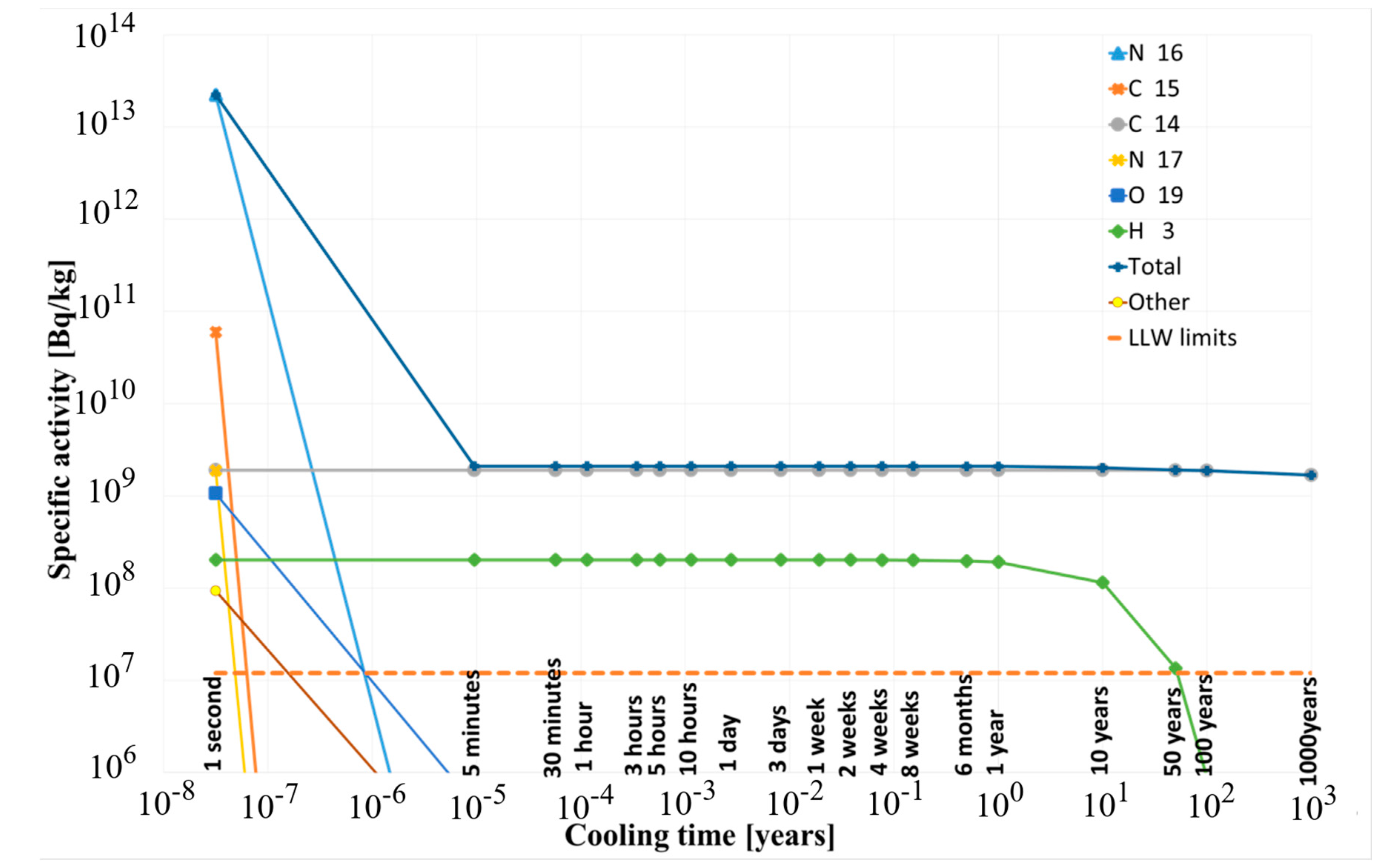
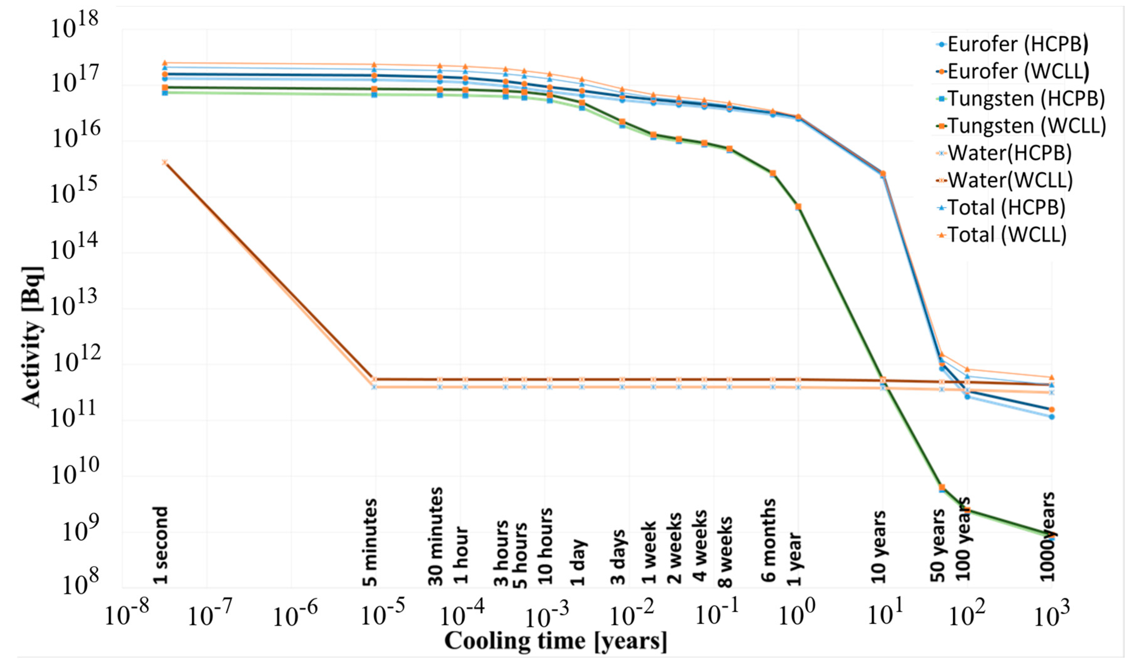
  • Water: 4.20 × 10¹⁵ Bq to 3.16 × 10¹¹ Bq;
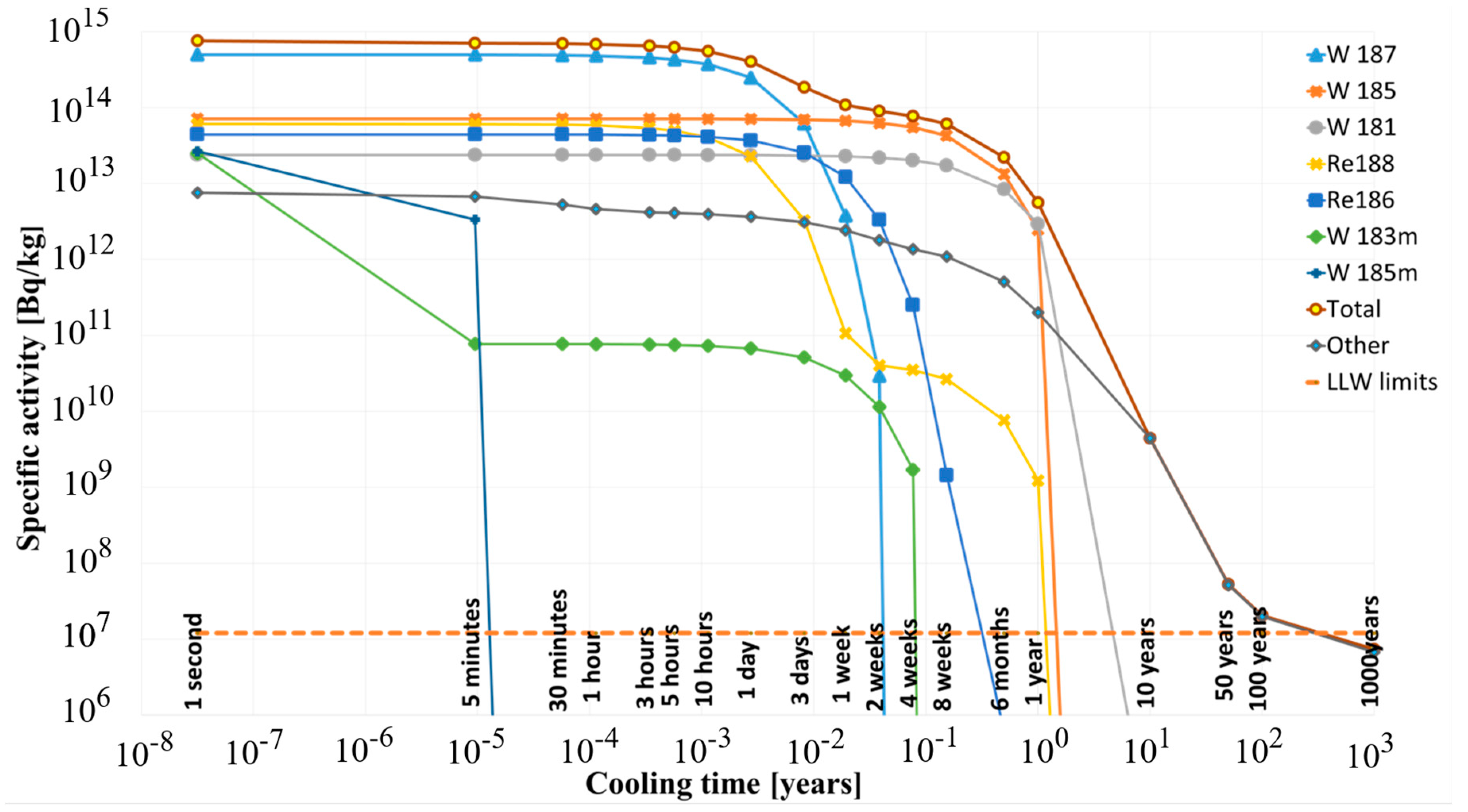
  • Tungsten 7.42 × 10¹⁶ Bq to 0.802 × 10⁹ Bq;
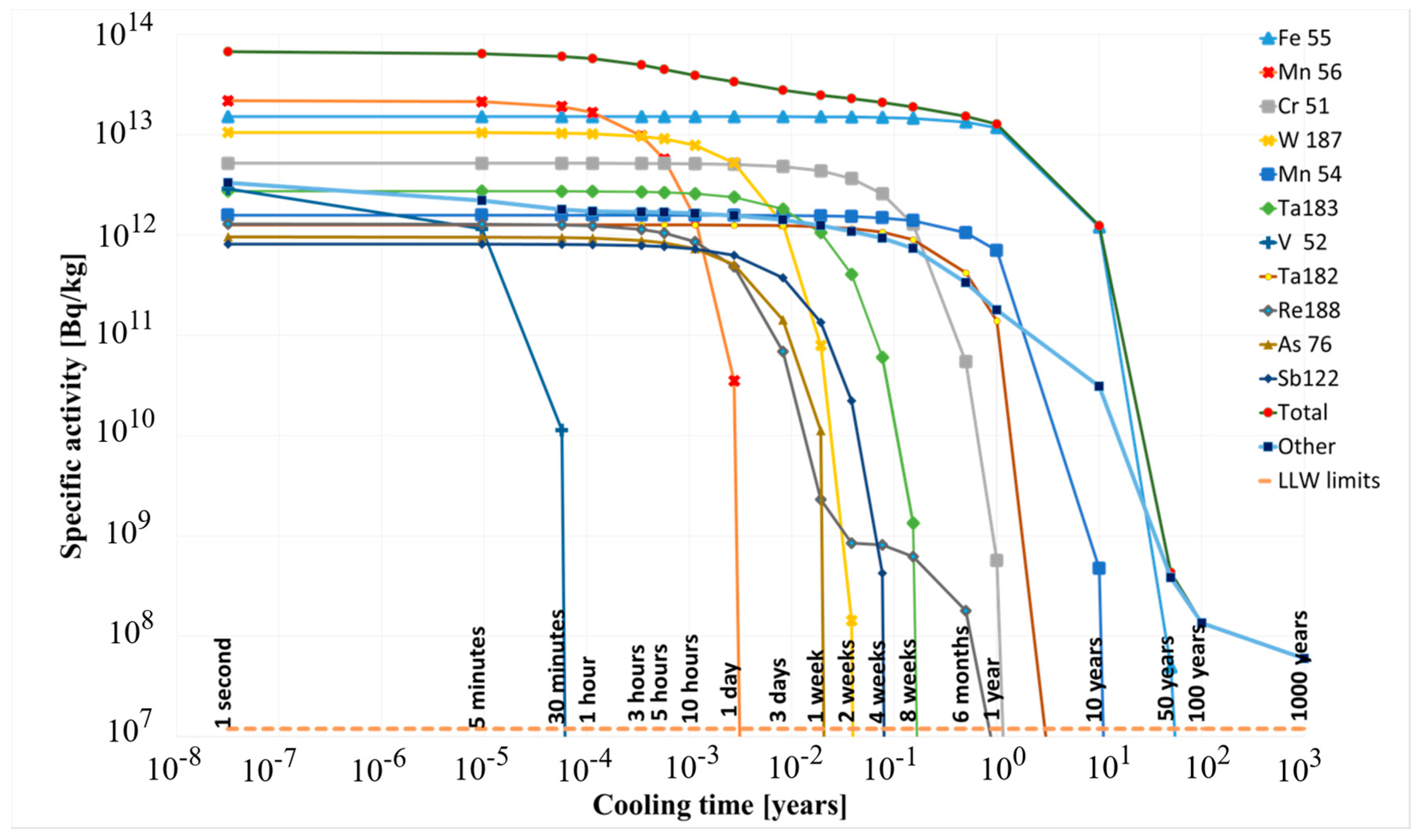
  • Eurofer 1.32 × 10¹⁷ Bq to1.17 × 1011 Bq.
Analogously, regarding the total activity for the WCLL concept, the decrease from 2.545 × 10¹⁷ Bq to 5.929 × 10¹¹ Bq is obtained, and each material’s (0 s–1000 years) information is presented below, where:
  • Water: 4.19 × 10¹⁵ Bq to 4.34 × 10¹¹ Bq;
  • Tungsten 9.202 × 10¹⁶ Bq to 0.90 × 10⁹ Bq;
  • Eurofer 1.58 × 10¹⁷ Bq to 1.57 × 10¹¹ Bq (see Figure 9 for more information).
These results have shown that the activation significantly decreased. Having these numbers in mind, we can state that in both DEMO concept models, divertor linear and reflector plates should be classified as intermediate level waste (ILW) based on the IAEA standards book “Classification of Radioactive Waste” [41]. ILW contains the amount of long-lived radionuclides (gamma activation level—12 MBq/kg), which requires isolation and more advanced engineered physical barriers, and needs to be disposed of at a depth ranging from tens up to a few hundreds of meters. The results in this paper are in good agreement with Ref. [42], where it is stated that the steel of the divertor will remain as ILW for decades or even centuries after shutdown. According to IAEA, this level of waste needs higher than near-surface disposal. In addition, LLW contains radionuclides of lower activity than ILW and limited concentrations of long-lived radionuclides. This kind of waste already requires contamination and barriers for isolation in near-surface disposal facilities for periods up to a few hundreds of years. Long-lived radionuclides may be present in ILW and may not decay to a level of activity concentration appropriate for near-surface disposal over the period covered by institutional regulations. As a result, radionuclide waste in this category must be disposed of at deeper depths, ranging from tens of meters to a few hundred meters [41].
Compared with the previous model (in Figure 10), the 2019 divertor model is more complicated, without clearly defined parts. The previous model was comprised of four functional layers:
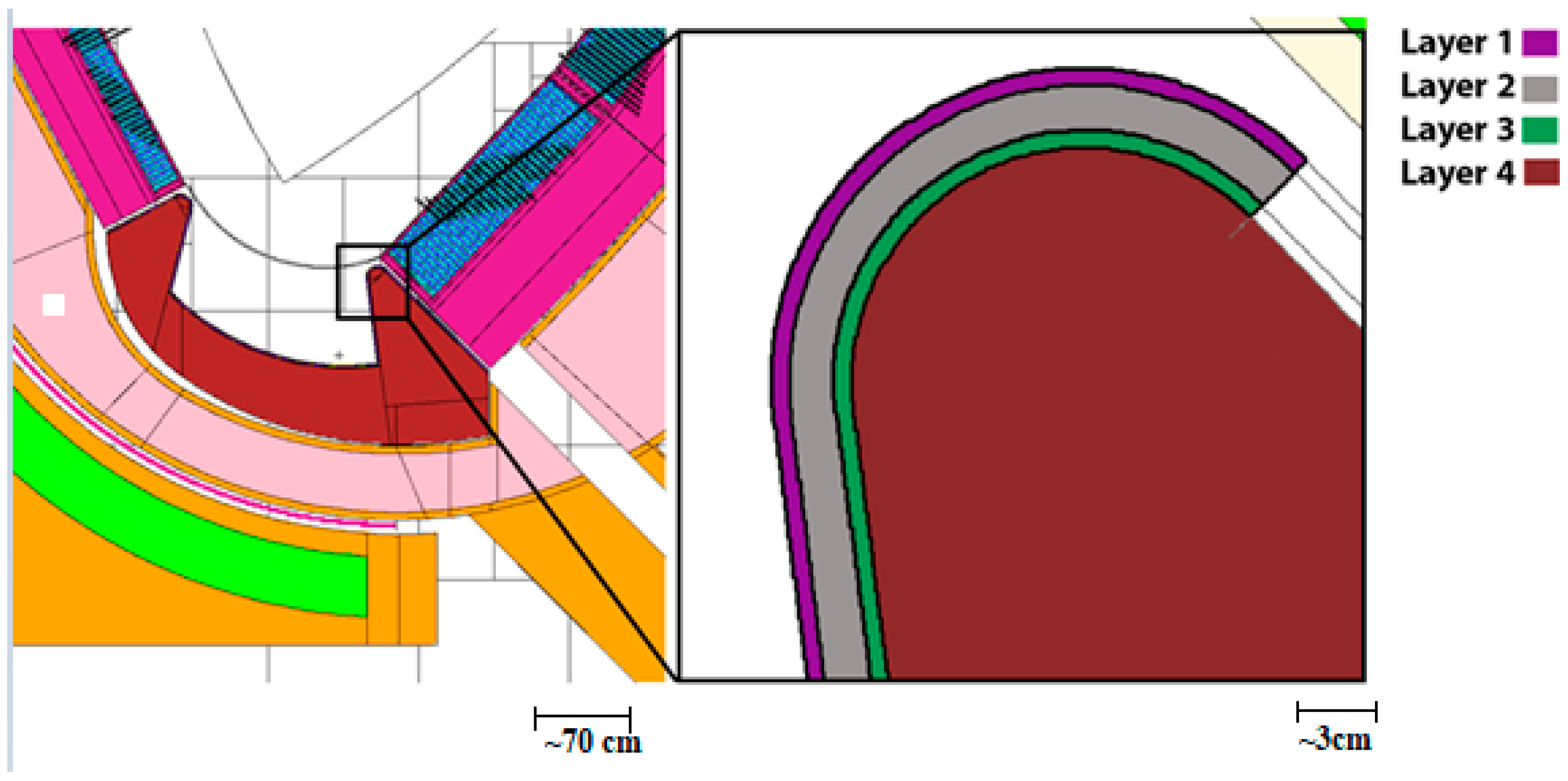
  • Layer 1 was made of tungsten.
  • Layer 2 was made of tungsten, CuCrZr, Cu alloy, and water.
  • Layer 3 was made of tungsten.
  • Layer 4 was made of EUROFER steel and water [43].
From both calculations, the same material (tungsten and Eurofer) nuclide analysis showed that the identical nuclides are most dominant at the same time, despite the fact that parts with Eurofer are mixed with water in previous calculations [43]. As for activity calculations, a comparison between this work and older estimates could be made with the first layer, i.e., tungsten materials. The activity of the 3 mm layer in this work is approximately six times higher than the first layer in Ref. [43], up to ten years of cooling. If we consider a later time interval, the activation values in Ref. [43] are lower by approximately two orders of magnitude for the first layer of divertor. This is due to the use of different nuclear data libraries. In addition, only plates are considered in these calculations, and the first layer corresponded for plates and PFC together in the previous DEMO divertor model used in Ref. [43]. For detailed information, see Figure 11.
Using the same model, Noce S. et al. [16] performed neutronics analysis and activation calculations for tungsten used in the DEMO divertor targets. PFC, liner, and reflector plates have similar primary functions. Thus, neutrons energy spectra observed in all of these components should be similar, as they have primary interactions with produced neutrons by the fusion reaction inside the vacuum vessel (VV) of DEMO tokamak. In comparison, we will consider reflector plates (this work) and PFC’s monoblocks [16], which showed the highest value in the first cooling second. Two points representing PFCs (one from inboard and one from outboard) in the MCNP geometry model from [16] were chosen as the most energetic neutrons hit PFC at this location. This assumption is analogous to the liner and reflector plates location in the divertor considered in the present work. The present work and available data from Ref. [16] showed that specific activity of PFCs (located in the inboard of the VV) is higher by 9% and 15% in comparison with inboard reflector plates for WCLL and HCPB, respectively. Moreover, PFCs at the outboard have activity values higher by approximately 15% and 29% than at the outboard of reflector plates in the WCLL and HCPB concept models correspondingly (see Table 3 for more details).

5. Summary

The objective of this study was to calculate the activity induced by neutron irradiation in DEMO divertor liner and reflector plates’ structure. The calculations were performed with MCNP6 and FISPACT II codes. The specific activities were calculated for the European DEMO nuclear fusion reaction after 5.2 calendar years of its lasting operation. The cooling period was considered spanning for up to 1000 years. Additionally, radionuclides with a contribution of at least 1% to the total value were identified.
The main radioisotopes identified as responsible for the activity were:
  • At the beginning of cooling time: 55Fe, 56Mn, 187W, 16N, 52V;
  • After one year: 55Fe, 185W; and
  • 14C dominates in water for 100 years and beyond.
This study evaluated the nuclear waste produced during European DEMO divertor liner and reflector plate cooling, and the differences between the two types of breeder blanket module configurations were evaluated. These differences are essential for the divertor liner and reflector plate cooling approach consideration.
Although divertor geometry was developed in both models, the total neutron-induced activity is on average 1.19 times higher using the WCLL model. In different materials, this value is diverse:
  • In water, activity is higher using the HCPB breeding blanket, but activity is higher in WCLL, approximately 1.37 times later.
  • In tungsten material, values differ 1.24 times at the first second after shutdown, and 1.07 times after 100 years.
  • In Eurofer material, activity differs 1.20 times at the first second, and around 1.10 times after ten years.
Total activity from the beginning of cooling until 1000 years of liner and reflector plates decreases from 2.103 × 10¹⁷ Bq to 4.336 × 10¹¹ Bq in the HCPB concept and falls from 2.545 × 10¹⁷ Bq to 5.929 × 10¹¹ with the WCLL concept. These results have shown that a year after shutdown, divertor liner and reflector plates should be processed as intermediate level waste for more than a thousand years. The HCPB breeding blanket concept showed better results from an environmental perspective since the activity values were smaller than the values obtained using the WCLL breeding blanket model. Despite that, overall factors should be taken into account—whole reactor activity, decay heat, tritium production rates, etc.—in order to have the full picture of radiological inventories for the DEMO reactor.

Author Contributions

Conceptualization, S.B. and G.S.; methodology, S.B. and G.S.; software, G.S.; formal analysis, S.B.; investigation, S.B. and G.S.; data curation, S.B. and G.S.; writing—original draft preparation, S.B.; writing—review and editing, G.S.; visualization, S.B.; supervision, G.S.; All authors have read and agreed to the published version of the manuscript.

Funding

This work has been carried out within the framework of the EUROfusion Consortium and has received funding from the Euratom research and training programme 2014–2018 and 2019–2020 under grant agreement No. 633053. The views and opinions expressed herein do not necessarily reflect those of the European Commission.

Conflicts of Interest

The authors declare no conflict of interest.

References

  1. Kemfert, C. Green Deal for Europe: More Climate Protection and Fewer Fossil Fuel Wars. Intereconomics 2019, 54, 353–358. [Google Scholar] [CrossRef] [Green Version]
  2. Chen, F.F. Plasma Applications Introduction to Plasma Physics and Controlled Fusion; Springer: Cham, Switzerland, 2016. [Google Scholar] [CrossRef]
  3. Hughes, J. Making isotopes matter: Francis Aston and the mass-spectrograph. Dynamis 2009, 29, 131–165. [Google Scholar] [CrossRef]
  4. Wu, Y.C.; Chen, Z.B.; Hu, L.Q. Identification of safety gaps for fusion demonstration reactors. Nat. Energy 2016, 1, 1–11. [Google Scholar] [CrossRef]
  5. Wu, Y.C.; Stevens, E.; Kim, K. Summary of the 1st international workshop on environmental, safety and economic aspects of fusion power. Nucl. Fusion 2016, 54, 127001. [Google Scholar] [CrossRef]
  6. Donné, A.J.H. The European roadmap towards fusion electricity. Philos. Trans. R. Soc. A Math. Phys. Eng. Sci. 2019, 377, 20170432. [Google Scholar] [CrossRef] [PubMed] [Green Version]
  7. Turcanu, C.; Prades, A.; Sala, R.; Perko, T.; Oltra, C. Fusion energy: A deeper look into attitudes among the general public. Fusion Eng. Des. 2020, 161, 111891. [Google Scholar] [CrossRef]
  8. Realising Fusion Electricity. Available online: https://www.euro-fusion.org/eurofusion/roadmap/ (accessed on 3 September 2021).
  9. Sawan, M.E.; Abdou, M.A. Physics and technology conditions for attaining tritium self-sufficiency for the DT fuel cycle. Fusion Eng. Des. 2006, 81, 1131–1144. [Google Scholar] [CrossRef]
  10. Federici, G.; Bachmann, C.; Barucca, L.; Biel, W.; Boccaccini, L.; Brown, R.; Bustreo, C.; Ciattaglia, S.; Cismondi, F.; Coleman, M.; et al. DEMO design activity in Europe: Progress and updates. Fusion Eng. Des. 2018, 136, 729–741. [Google Scholar] [CrossRef]
  11. Ciattaglia, S.; Federici, G.; Barucca, L.; Lampasi, A.; Minucci, S.; Moscato, I. The European DEMO fusion reactor: Design status and challenges from balance of plant point of view. In Proceedings of the 2017 IEEE International Conference on Environment and Electrical Engineering and 2017 IEEE Industrial and Commercial Power Systems Europe (EEEIC/I&CPS Europe), Milan, Italy, 6–9 June 2017; pp. 1–6. [Google Scholar]
  12. Gliss, C.; Ciattaglia, S.; Korn, W.; Moscato, I. Initial layout of DEMO buildings and configuration of the main plant systems. Fusion Eng. Des. 2018, 136, 534–539. [Google Scholar] [CrossRef]
  13. You, J.; Mazzone, G.; Visca, E.; Bachmann, C.; Autissier, E.; Barrett, T.; Cocilovo, V.; Crescenzi, F.; Domalapally, P.; Dongiovanni, D.; et al. Conceptual design studies for the European DEMO divertor: Rationale and first results. Fusion Eng. Des. 2015, 109, 1598–1603. [Google Scholar] [CrossRef] [Green Version]
  14. Bachmann, C.; Ciattaglia, S.; Cismondi, F.; Eade, T.; Federici, G.; Fischer, U.; Franke, T.; Gliss, C.; Hernandez, F.; Keep, J.; et al. Overview over DEMO design integration challenges and their impact on component design concepts. Fusion Eng. Des. 2018, 136, 87–95. [Google Scholar] [CrossRef]
  15. Mazzone, G.; You, J.-H.; Bachmann, C.; Bonavolontà, U.; Cerri, V.; Coccorese, D.; Dongiovanni, D.; Flammini, D.; Frosi, P.; Forest, L.; et al. Eurofusion-DEMO Divertor-Cassette Design and Integration. Fusion Eng. Des. 2020, 157, 111656. [Google Scholar] [CrossRef]
  16. Noce, S.; Flammini, D.; Mariano, G.; Mazzone, G.; Moro, F.; Romanelli, F.; Villari, R.; You, J.-H. Neutronics analysis and activation calculation for tungsten used in the DEMO divertor targets: A comparative study between the effects of WCLL and HCPB blanket, different W compositions and chromium. Fusion Eng. Des. 2021, 169, 112428. [Google Scholar] [CrossRef]
  17. Marzullo, D.; Bachmann, C.; Coccorese, D.; Di Gironimo, G.; Frosi, P.; Mazzone, G.; You, J.-H. Progress in the pre-conceptual CAD engineering of European DEMO divertor cassette. Fusion Eng. Des. 2019, 146, 942–945. [Google Scholar] [CrossRef] [Green Version]
  18. Mazzone, G.; You, J.-H.; Bachmann, C.; Bonavolontà, U.; Cerri, V.; Coccorese, D.; Dongiovanni, D.; Flammini, D.; Frosi, P.; Forest, L.; et al. WPDIV-1-T005 Loads Specification (LS) for Divertor Cassette 2018 (Incl. Neutronics, EM Analysis), IDM Ref. EFDA_D_2NLWLE v1.0. Available online: https://idm.euro-fusion.org/default.aspx?uid=2NLWLE (accessed on 27 November 2021).
  19. di Maio, P.A.; Burlon, R.; Giardina, M.; You, J.H.; Mazzone, G. On the numerical assessment of the thermal-hydraulic operating map of the DEMO Divertor Plasma Facing Components cooling circuit. Fusion Eng. Des. 2020, 161, 111919. [Google Scholar] [CrossRef]
  20. Federici, G.; Kemp, R.; Ward, D.; Bachmann, C.; Franke, T.; Gonzalez, S.; Lowry, C.; Gadomska, M.; Harman, J.; Meszaros, B.; et al. Overview of EU DEMO design and R&D activities. Fusion Eng. Des. 2014, 89, 882–889. [Google Scholar] [CrossRef]
  21. Klein, F.; Litnovsky, A.; Tan, X.; Gonzalez-Julian, J.; Rasinski, M.; Linsmeier, C.; Bram, M.; Coenen, J.W. Smart alloys as armor material for DEMO: Overview of properties and joining to structural materials. Fusion Eng. Des. 2021, 166, 112272. [Google Scholar] [CrossRef]
  22. Richardson, M.; Gorley, M.; Wang, Y.; Aiello, G.; Pintsuk, G.; Gaganidze, E.; Richou, M.; Henry, J.; Vila, R.; Rieth, M. Technology readiness assessment of materials for DEMO in-vessel applications. J. Nucl. Mater. 2021, 550, 152906. [Google Scholar] [CrossRef]
  23. Pereslavtsev, P.; Cismondi, F.; Hernández, F.A. Analyses of the shielding options for HCPB DEMO blanket. Fusion Eng. Des. 2020, 156, 111605. [Google Scholar] [CrossRef]
  24. Moscato, I.; Barucca, L.; Ciattaglia, S.; D’Aleo, F.; Di Maio, P.; Federici, G.; Tarallo, A. Progress in the design development of EU DEMO helium-cooled pebble bed primary heat transfer system. Fusion Eng. Des. 2019, 146, 2416–2420. [Google Scholar] [CrossRef]
  25. Zhou, G.; Hernández, F.A.; Zeile, C.; Maione, I.A. Transient thermal analysis and structural assessment of an ex-vessel LOCA event on the EU DEMO HCPB breeding blanket and the attachment system. Fusion Eng. Des. 2018, 136, 34–41. [Google Scholar] [CrossRef] [Green Version]
  26. Hernández, F.; Pereslavtsev, P.; Kang, Q.; Norajitra, P.; Kiss, B.; Nádasi, G.; Bitz, O. A new HCPB breeding blanket for the EU DEMO: Evolution, rationale and preliminary performances. Fusion Eng. Des. 2017, 124, 882–886. [Google Scholar] [CrossRef]
  27. Brown, F.B.; Kiedrowski, B.C.; Bull, J.S. Verification of MCNP6.1 and MCNP6.1.1 for Criticality Safety Applications; United States, Los Alamos National Laboratory: Los Alamos, NM, USA, 2014. [Google Scholar] [CrossRef] [Green Version]
  28. Hasegawa, A.; Fukuda, M.; Tanno, T.; Nogami, S. Neutron Irradiation Behavior of Tungsten. Mater. Trans. 2013, 54, 466–471. [Google Scholar] [CrossRef] [Green Version]
  29. Tavassoli, F. Eurofer Steel, Development to Full Code Qualification. Procedia Eng. 2013, 55, 300–308. [Google Scholar] [CrossRef] [Green Version]
  30. Kroese, D.P.; Bretenon, T.; Taimre, T.; Botev, Z.I. Why the Monte Carlo method is so important today. WIREs Comput. Stat. 2014, 6, 386–392, [retrieved on 2020-03-23]. [Google Scholar] [CrossRef]
  31. Dunn, W.L.; Shultis, J.K. Exploring Monte Carlo Methods; Elsevier: Amsterdam, The Netherlands, 2011; ISBN 978-0-444-51575-9. [Google Scholar]
  32. X-5 Monte Carlo Team, MCNP- a General Monte Carlo N-Particle Transport Code, Version 5, 2003, LA-UR-03-1987. Available online: https://mcnp.lanl.gov/pdf_files/la-ur-03-1987.pdf (accessed on 28 November 2021).
  33. Sublet, J.-C.; Eastwood, J.; Morgan, J.; Gilbert, M.; Fleming, M.; Arter, W. FISPACT-II: An Advanced Simulation System for Activation, Transmutation and Material Modelling. Nucl. Data Sheets 2017, 139, 77–137. [Google Scholar] [CrossRef]
  34. Koning, J.; Rochman, D. Modern Nuclear Data Evaluation with The TALYS Code System. Nucl. Data Sheets 2012, 113, 2841–2934. [Google Scholar] [CrossRef]
  35. Koning, A.J.; Rochman, D.; Sublet, J.-C.; Dzysiuk, N.; Fleming, M.; van der Marck, S. TENDL: Complete Nuclear Data Library for Innovative Nuclear Science and Technology. Nucl. Data Sheets 2019, 155, 1–55. [Google Scholar] [CrossRef]
  36. Kwon, S.; Konno, C.; Ohta, M.; Ochiai, K.; Sato, S.; Kasugai, A. TENDL-2017 benchmark test with iron shielding experiment at QST/TIARA. Fusion Eng. Des. 2019, 144, 209–214. [Google Scholar] [CrossRef]
  37. Forrest, R.A. FISPACT-2007: User Manual. Technical Report Ukaea FUS 534; Euratom/Ukaea Fusion Association, Culham Science centre: Abingdon, UK, 2007. [Google Scholar]
  38. Ďuran, I.; Entler, S.; Grover, O.; Bolshakova, I.; Výborný, K.; Kočan, M.; Jirman, T.; Vayakis, G.; Vasyliev, O.; Radishevskyi, M.; et al. Status of steady-state magnetic diagnostic for ITER and outlook for possible materials of Hall sensors for DEMO. Fusion Eng. Des. 2019, 146, 2397–2400. [Google Scholar] [CrossRef]
  39. Batistoni, P.; Angelone, M.; Petrizzi, L.; Pillon, M. Experimental validation of shut down dose rates calculations inside ITER cryostat. Fusion Eng. Des. 2001, 58, 613–616. [Google Scholar] [CrossRef]
  40. Fisher, U. PMI-5.3-035 Guidelines for Neutronic Analyses, IDM Ref. EFDA_D_2L8TR9. Available online: https://idm.euro-fusion.org/default.aspx?uid=2L8TR9 (accessed on 28 November 2021).
  41. IAEA Safety Standards: Classification of Radioactive Waste, Tech. Rep. General Safety Guide: GSG-1. 2009. Available online: https://www-pub.iaea.org/MTCD/publications/PDF/Pub1419_web.pdf (accessed on 27 November 2021).
  42. Gilbert, M.; Eade, T.; Bachmann, C.; Fischer, U.; Taylor, N. Activation, decay heat, and waste classification studies of the European DEMO concept. Nucl. Fusion 2017, 57, 046015. [Google Scholar] [CrossRef] [Green Version]
  43. Tidikas, A.; Stankunas, G. Activation analysis of the European DEMO divertor with respect to the different breeding blanket segmentation. Fusion Eng. Des. 2020, 161, 112012. [Google Scholar] [CrossRef]
Figure 1. (a) Computer- Aided Dsesign (CAD) model of 2019 DEMO divertor assembly, with the length of the divertor [15]; (b) CAD model of 2019 DEMO divertor assembly, with main parts [15].
Energies 14 08305 g001aEnergies 14 08305 g001b
Figure 2. 2019 Divertor CAD Model: Reflector Plates [15].
Energies 14 08305 g002
Figure 3. Divertor assembly section with detail of cassette section and cassette cooling path [15].
Energies 14 08305 g003
Figure 4. EU DEMO MCNP model with Helium-Cooled Pebble Bed (HCPB) (Left) and Water-Cooled Lithium Lead (WCLL) (Right) layered blanket concept.
Energies 14 08305 g004
Figure 5. Divertor MCNP model: (a) with extracted linear and reflector plates; (b) 1—Tungsten, 2—Water, 3—Eurofer layers. (PFC—Plasma Facing Component).
Energies 14 08305 g005
Figure 6. The specific activity of Eurofer in the liner and reflector plates (HCPB concept) with Low Level Waste (LLW) line.
Energies 14 08305 g006
Figure 7. The specific activity of tungsten in the liner and reflector plates (WCLL concept).
Energies 14 08305 g007
Figure 8. The specific activity of water in the liner and reflector plates (HCPB concept).
Energies 14 08305 g008
Figure 9. Activation in the liner and reflector plates of HCPB and WCLL concepts.
Energies 14 08305 g009
Figure 10. MCNP model of the divertor cassette [43].
Energies 14 08305 g010
Figure 11. Comparison of total activities (in liner and reflector plates containing 3 mm of tungsten layer (present work)) and the first layer of divertor in [43].
Energies 14 08305 g011
Table 1. Main parameters of the DEMO1 baseline configuration [16].
N of toroidal field coils16
Major radius (m)8.938
Minor radius (m)2.883
Aspect ratio3.1
Plasma elongation1.65
Plasma triangularity0.33
Fusion power (MW)1998
Table 2. Divertor linear and reflector plates material composition (wt %).
EuroferTungstenWater
M5M15m100
7.798 g/cm319.25 g/cm30.926 g/cm3
Elementwt %Elementwt %Elementwt %Elementwt %Elementwt %Elementwt %
Fe88.698Mn0.4Al0.0015N0.0005As0.0005H11.2
B0.002Co0.01C0.003Na0.001Ba0.0005O88.8
C0.11Ni0.01Ca0.0005Nb0.001Cd0.0005
N0.03Cu0.01Co0.001Ni0.0005Zn0.0005
O0.01Nb0.005Cr0.002O0.002W99.9595
Al0.01Mo0.005Cu0.001P0.002Ag0.001
Si0.05Ta0.12Fe0.003Pb0.0005As0.0005
P0.005W1.1H0.0005S0.0005Ba0.0005
S0.005As0.05K0.001Si0.002Cd0.0005
Ti0.02Sn0.05Mg0.0005Ta0.002Zn0.0005
V0.2Sb0.05Mn0.0005Ti0.0005
Cr9Zr0.05Mo0.01Zr0.0005
Table 3. Comparison of specific activity with Ref. [16] [Bq/kg].
WCLLHCPB
Ref. [16]Present WorkRef. [16]Present Work
InboardOutboardInboard ReflectorOutboard ReflectorInboardOutboardInboard ReflectorOutboard Reflector
1 s5.17 × 10145.16 × 10145.83 × 10144.54 × 10144.37 × 10144.39 × 10144.52 × 10143.61 × 1014
1 year5.76 × 10125.37 × 10123.97 × 10123.52 × 10125.59 × 10125.17 × 10123.67 × 10123.29 × 1012
50 years3.61 × 1073.44 × 1073.87 × 1073.29 × 1073.38 × 1073.24 × 1073.42 × 10122.92 × 107
Publisher’s Note: MDPI stays neutral with regard to jurisdictional claims in published maps and institutional affiliations.

