Abstract
The analytical model of a permanent magnet eddy current coupler (PMECC) is mainly used for evaluation of its characteristics and the initial optimization of design. Based on the equivalent magnetic circuit method, this paper carries out analytical modeling for four typical PMECCs composed of surface-mounted and interior permanent magnet, slotted and non-slotted conductor rotors, which provides a theoretical basis for the subsequent research in this paper. The basic electromagnetic characteristics of the PMECCs are investigated by the established analytical model. Simultaneously, the analytical results about permeance, flux density, torque and power are verified by FEA simulation. The analysis results show that the slotted CR will obtain a much higher power density, and the iron loss mainly exists in the CRs. In addition, the analytical and FEA results agree well, which proves the reliability of the proposed, nearly unified analytical model.
1. Introduction
A permanent magnet eddy current coupler (PMECC) mainly consists of a permanent magnet rotor (PMR) and a conductor rotor (CR). Usually, the CR is connected to the input shaft which is also known as an active rotor; the PMR is connected to the output shaft which is also known as a driven rotor. PMECCs can be used in many industrial applications such as blowers, conveyors, and pumps, which can transmit a torque or adjust output speed in a drive system without any physical contact [1,2,3]. In addition, they also can be used in the braking systems of trucks, trains, and other devices [1,4,5]. Compared with traditional mechanical couplings, they offer substantial advantages such as high power density, contactless, vibration limitation, natural protection against overload, reduced maintenance and great tolerance to shaft misalignment [1,2,3,4,5].
From the direction of the main magnetic flux, the PMECC can be divided into axial-flux (disk type) [2,6,7,8,9] and radial-flux (cylinder type) structures [10,11,12]. The PMR of PMECC is mainly composed of PM and a back iron core, which is similar to the traditional rotor of a PM motor. The PM layout mainly adopts surface-mounted PM (SPM) and interior PM (IPM). The CR of PMECC mainly contains non-slotted and slotted structures. The former consists of a constant thickness conductor sheet (CS)fixed on a back iron [13,14,15]; The latter is similar to the rotor of a squirrel-cage induction motor [7,16]. The analytical method of a PMECC is mainly summarized with vector magnetic potential and equivalent magnetic circuit (EMC) methods [9,13]. The former is usually used in a SPM rotor (SPMR), while the latter is more suitable for a special magnetic circuit structure [15,16,17]. has been studied in many works in the literature. Generally, the calculation of air-gap reluctance considering slot effect mainly contains two methods: (1) the relative permeance function is used to correct the calculation of the radial-flux slot-less motor, and the idea of conformal transformation is applied to the calculation of the magnetic permeance function [18,19,20,21,22]; (2) the Carter coefficient was derived by conformal mapping method [23,24].
At present, most improvements of PMECCs are based on the rotor structures mentioned above. Scholars have studied the basic electromagnetic and mechanical characteristics of PMECCs by combining theory and finite element analysis (FEA) methods, and some works in the literature have verified the reliability of theoretical analysis through prototype tests. However, there is a small amount of research on the summary of modeling methods and the performance of comparative analysis of the typical structure of PMECCs. In addition, it is difficult to undertake a unified comparison and analysis among the existing PMECCs with different structure parameters.
In this paper, four typical PMECCs are put together to maintain the same of permanent magnet volume, total cross-section area of conductor, and diameter of air-gap, so as to undertake the analysis and comparison. The main design parameters of the four typical PMECCs are listed in Appendix A: Table A1. Combining EMC and permeance function methods, the nearly universal analytical models of the four typical PMECCs are established in this paper to predict the performances efficiently. The magnetomotive force (MMF) and permeance model are built in Section 2, and the magnetic field calculation is processed in Section 3. In Section 4, the basic mechanical and electromagnetic characteristics are analyzed and comprehensively compared. Finally, Section 5 concludes this paper.
2. The Magnetomotive Force (MMF) and Permeance Model
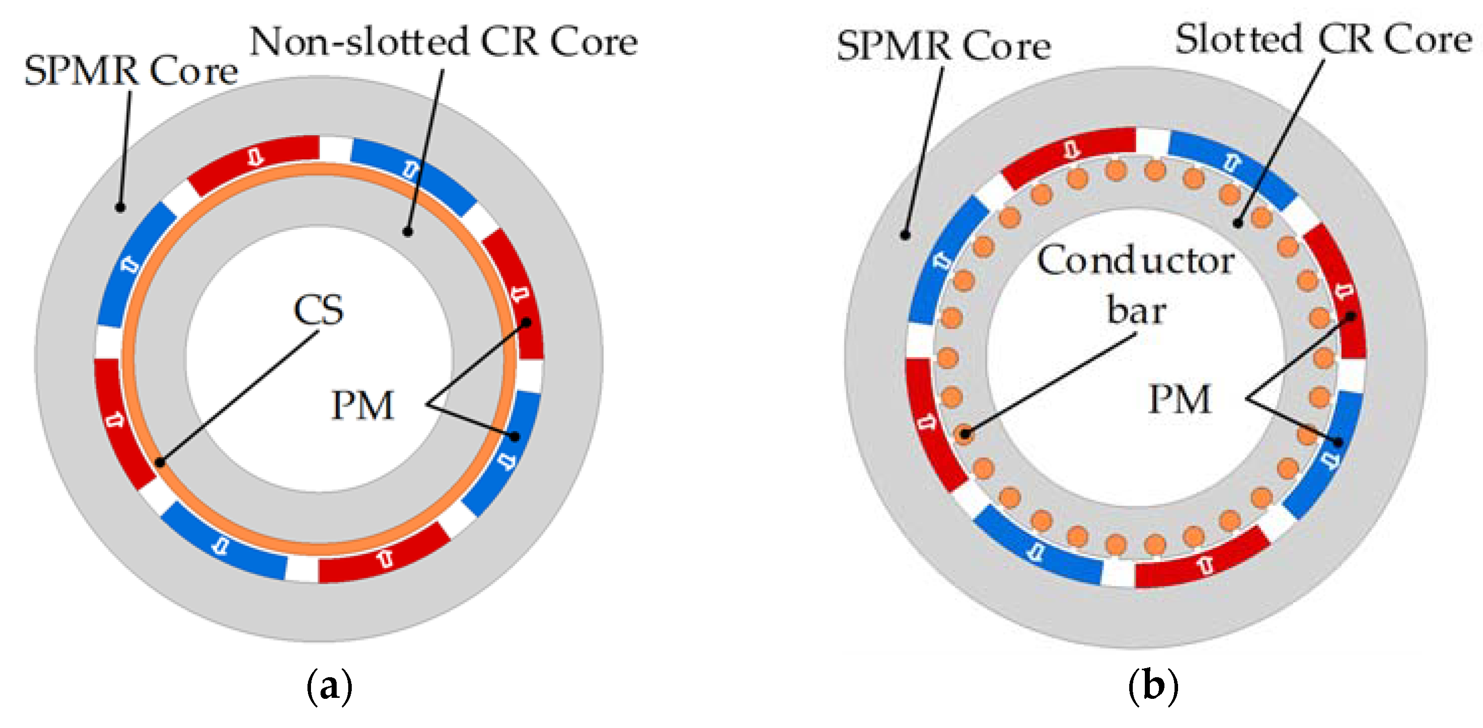
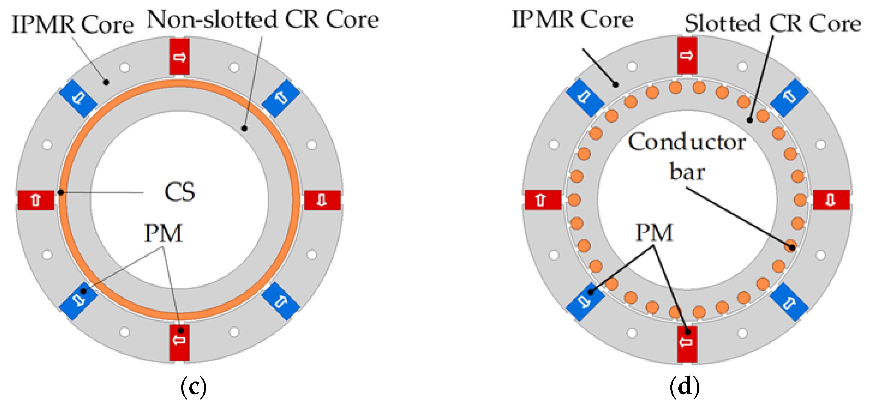
The radial-flux PMECC with an external PMR and an internal CR is taken as the research object of this paper. Analytical models of PMECCs with different combination models among SPMR and IPM rotor (IPMR), slotted and non-slotted CRs are mainly proposed in this section. For simplifying the descriptions, the four typical PMECCs are respectively marked as models A, B, C and D as shown in Figure 1. Both SPMR and IPMR are connected to the output shaft of a prime motor, which provides a rotating magnetic field with an almost constant speed. The eddy currents of PMECCs are respectively induced in the CS and conductor bars when a relative rotational motion happens between a CR and a PMR. Furthermore, a torque is generated on the CR according to Ampere’s theorem.
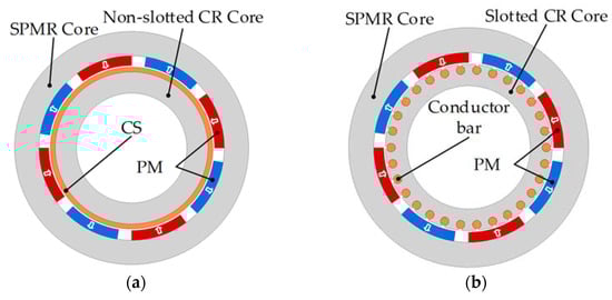
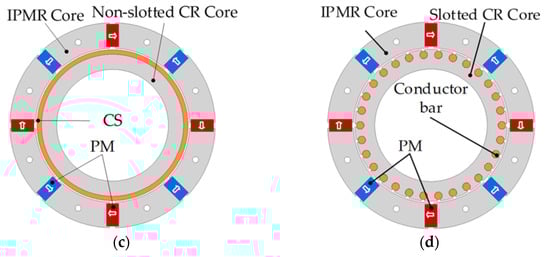
Figure 1.
The cross section of four typical permanent magnet eddy current couplers (PMECCs): (a) Model-A (surface-mounted permanent magnet rotor (SPMR) and non-slotted conductor rotor (CR)); (b) Model-B (SPMR and slotted CR); (c) Model-C (interior permanent magnet rotor (IPMR) and non-slotted CR); (d) Model-D (IPMR and slotted CR).
2.1. Modeling of MMF
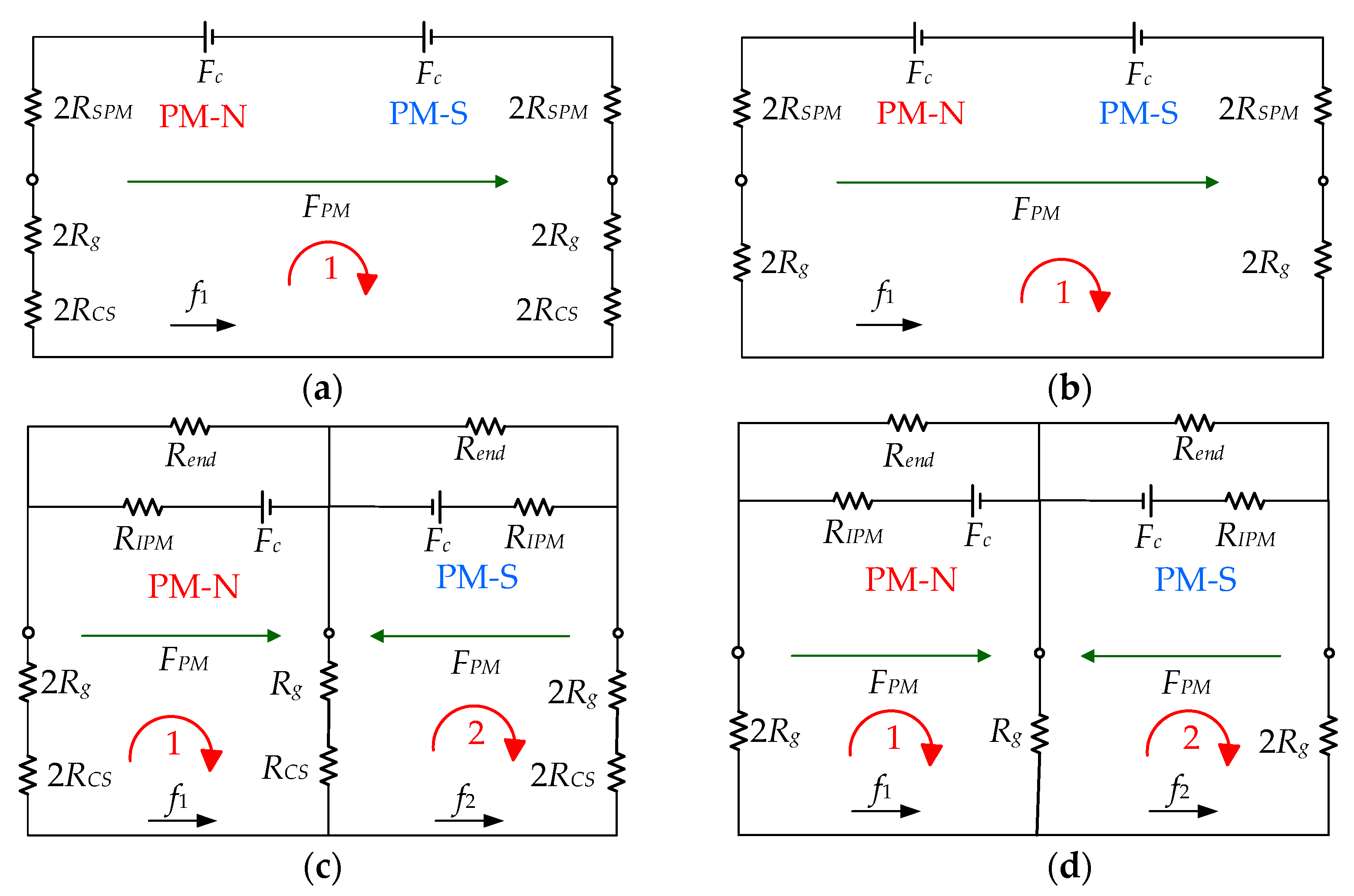
The EMC models of the four typical PMECCs mentioned above are established as shown in Figure 2. The magnetic circuit structures of the SPMRs are similar to those of the IPMRs, which include MMF source Fc and SPM reluctance. For the PMECCs with non-slotted CR, the outer magnetic circuit reluctance mainly includes air-gap reluctance and CS reluctance. For the PMECCs with slotted CR, the air-gap reluctance is mainly the external magnetic circuit reluctance. The reason is that the permeance of CS with copper or aluminum is close to that of air, while the permeance of iron cores is relatively large enough. Here, the slot effect is ignored in the EMC model, which will be considered in the further permeance function models. According to the Ampere circuital theorem, it is assumed that the magnetic potential difference of the core part is ignored, and the radial component of the no-load air-gap flux density can be expressed as:
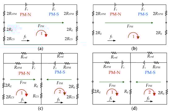
Figure 2.
The equivalent magnetic circuit (EMC) models of the four typical PMECCs: (a) Model-A; (b) Model-B; (c) Model-C; (d) Model-D.
The air-gap MMF was usually simulated by a rectangular wave, and the no-load and on-load magnetic field analytical models of the motor were obtained by using the permeance function method [18,19]. Based on the analysis of the EMC shown in Figure 2 and the flux leakage between adjacent poles, the air-gap MMF model of PMECCs can be simulated by a periodic standard trapezoidal wave to improve the calculation accuracy of air-gap flux density, as shown in Figure 3.
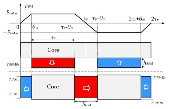
Figure 3.
Schematic diagrams of magnetomotive force (MMF) models with SPM and IPMR.
The MMF can be expressed by a piecewise function as:
According to the Fourier series, the expansion of (2) can be expressed in the interval [0, 2τp] as:
Combined with the EMC model as shown in Figure 2 and the MMF models shown in Figure 3, the amplitude FAm, FBm, FCm and FDm of the air-gap MMF waveform corresponding to models A, B, C and D can be respectively expressed as:
In a polar coordinate system, RCS, Rg, RSPM and RIPM can be respectively expressed as:
2.2. Air-Gap Permeance Model
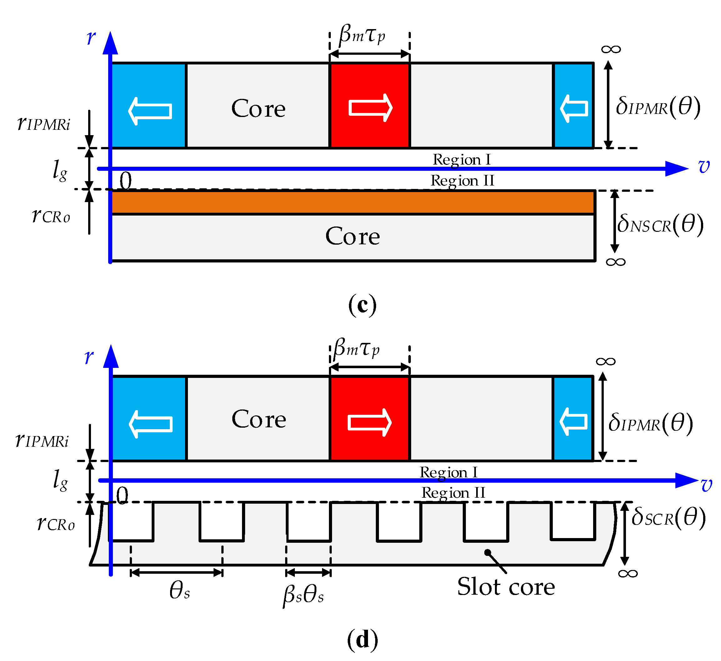
The relative permeance function is adopted in this paper, the air-gap is divided into two layers at the average radius of the air-gap, as shown in Figure 4 [18,19,20,21,22]. For details, it can be divided into: (1) air-gap permeance function at the side of SPMR or IPMR; (2) the air-gap permeance function at the side of slotted and non-slotted CRs.
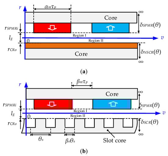

Figure 4.
The permeance models of the four typical PMECCs: (a) Model-A; (b) Model-B; (c) Model-C; (d) Model-D.
The permeance of models A to D can be given, respectively, as:
Figure 4a,b show the permeance models of the SPMRs. Since the permeance of the PM is basically the same as that of vacuum, δSPMR(θ) is a constant value, which is equal to hSPM. The permeance model of the IPMR is shown in Figure 4c,d. The IPM part can be regarded as an infinite deep slot. δIPMR(θ) can be obtained as [18,19]:
where βm = 1 − αm. According to the Fourier series, the expansion of (8) can be given in the interval [0, 2τp] as:
where
Figure 4a,c show the permeance models of the PMECCs with non-slots CR. Since the permeance of copper is basically the same as that of vacuum, δNSCR(θ) is equal to a constant value hCS. The permeance models of the PMECC with slotted CR are shown in Figure 4b,d. The slot of the CR core can be regarded as an infinite deep slot, and δSCR(θ) can be expressed as:
After linearization, Formula (13) can be expressed by the Fourier series as:
where
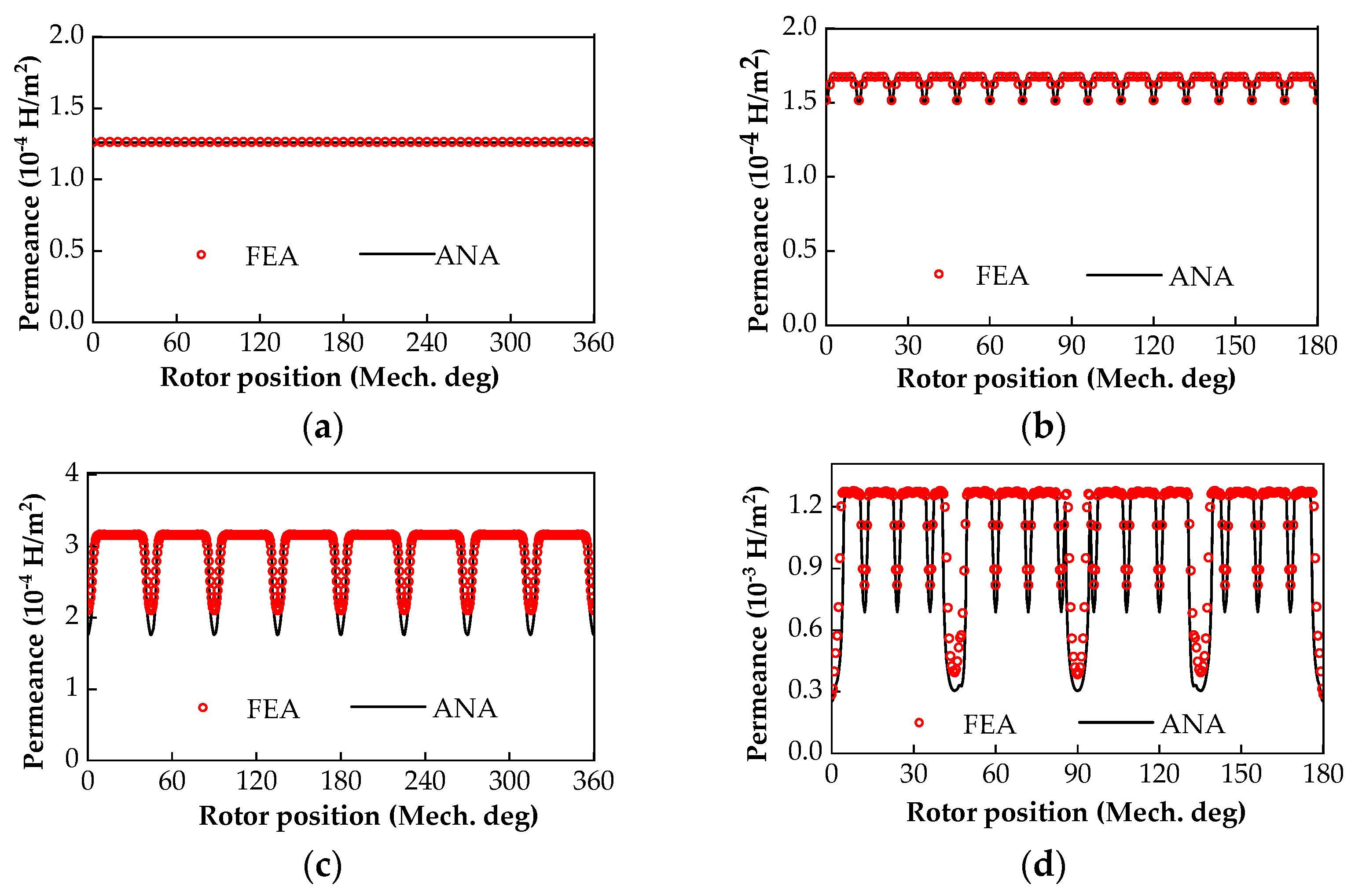
The analytical and FEA results of model−A to model−D are compared clearly in Figure 5. The permeance distribution of model−A is approximately linear, because its equivalent air-gap is uniform. The number of trough and flat-top wave heads of the permeance distribution of model−B is the same as the number of slots and teeth of the CR, respectively. The troughs of model−C are equal to the permanent magnet poles. The trough number of permeance distribution in model−D is in one-to-one correspondence with the number of PM poles and of CR slots. The analytical results of the permeance models are in good agreement with the FEA results, which also verifies the reliability of the proposed analytical permeance model.

Figure 5.
Air-gap permeance distribution of the four typical PMECCs: (a) Model-A; (b) Model-B; (c) Model-C; (d) Model-D.
3. Calculation of Air-Gap Magnetic Field
3.1. No-Load Air-Gap Magnetic Field
Based on the MMF, air-gap permeance model, and formula (1), the no-load air-gap flux densities of model−A to model−D can be obtained, respectively, as:
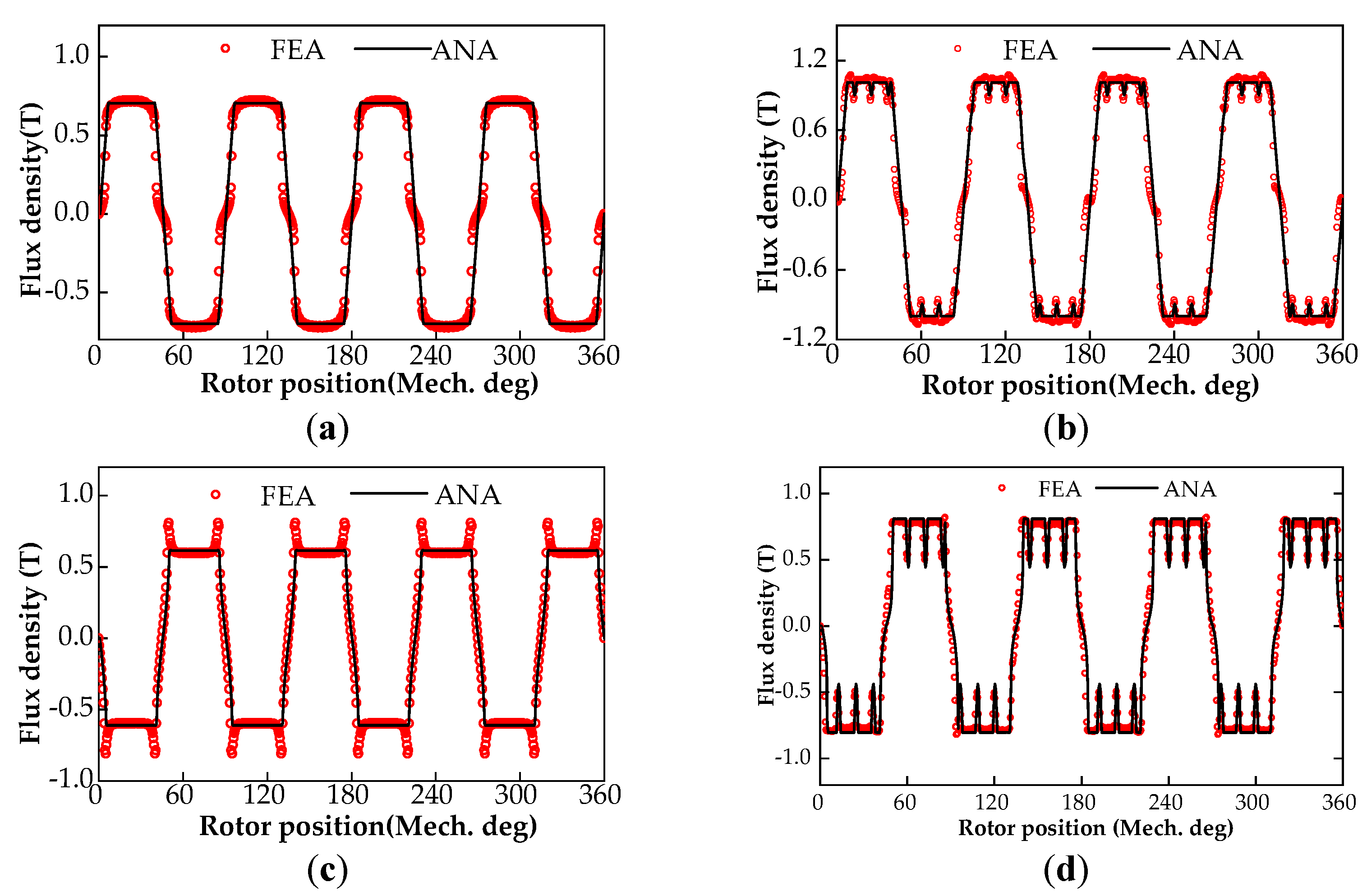
As shown in Figure 6, the no-load air-gap flux density calculated by the proposed analytical model are in good agreement with that of FEA. Under a given volume of permanent magnet, the amplitude of BNS(θ) is greater than that of BNI(θ), because the magnetic flux leakage of the PM at the outer radius of the IPMR is larger than that of SPMR. In addition, there are small errors between the analytical results and FEA, which is mainly caused by the influence of flux leakage between poles, groove shape and curvature effect in radial-flux structure. However, the magnetic flux of per pole obtained by the two methods is nearly identical. Therefore, the analytical model can be used to predict the air-gap magnetic field of PMECC efficiently, which provides a theoretical basis for the analysis of the basic electromagnetic characteristics and sensitivity of structural parameters of PMECCs.

Figure 6.
No-load air-gap flux density distribution of the four typical PMECCs: (a) Model-A; (b) Model-B; (c) Model-C; (d) Model-D.
3.2. On-Load Magnetic Field of Non-Slotted Conductor Rotor (CR)
Based on the eddy current induction principle of PMECC with non-slotted CR, the eddy current generated in the CS mainly depends on the total magnetic flux looped with the PMR and CR. It has little to do with the small fluctuation of the air-gap flux density waveform. According to the analysis of the no-load air-gap flux density distribution of model−A and model−B, the half-period air-gap flux density waveform is equivalent to the standard trapezoidal wave shown in Figure 7. In this way, the calculation process of electromagnetic parameters such as eddy current field, CR copper loss and output torque under load state can be simplified greatly [10,12]. The air-gap flux density can be expressed by a piecewise function as:
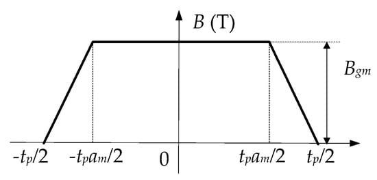
Figure 7.
The equivalent trapezoidal wave model of air-gap flux density of the PMECC with non-slotted CR.
The eddy current is induced in the CS when there is a relative rotation between the PMR and the CR of PMECCs. Then, the eddy current density can be obtained as:
where r and ω are radius and relative rotation angular velocity, respectively. Under an on-load state, the air-gap magnetic density of the PMECC with non-slotted CR can be expressed as:
The eddy current field can be calculated according to the Ampere loop theorem:
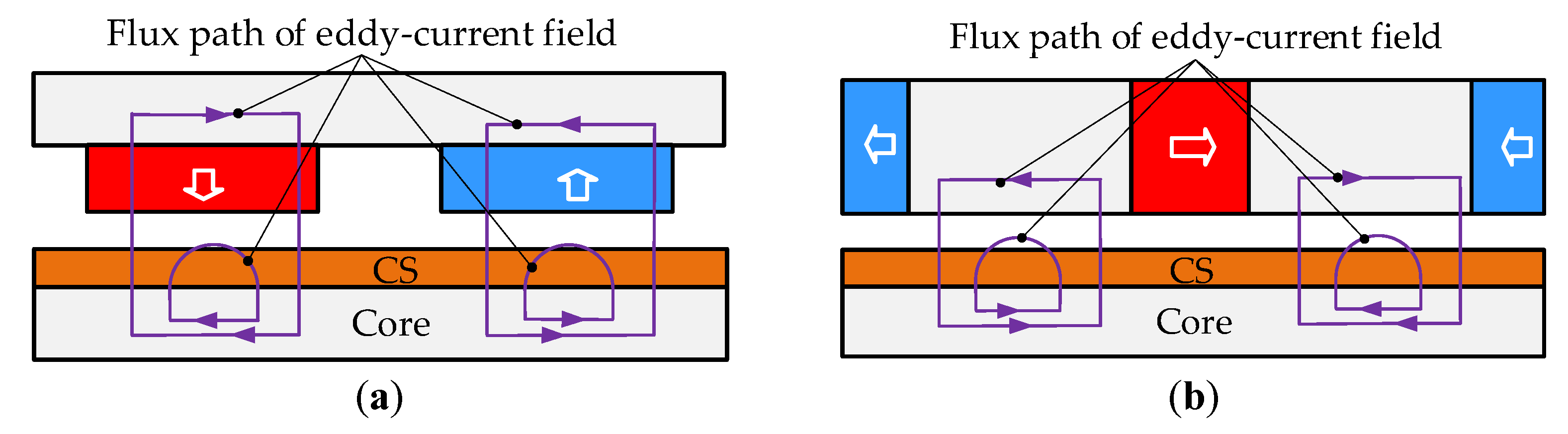
Assumptions: (1) the permeance of PM is the same as that of a vacuum; (2) the permeance of the core is infinite; (3) the cores of PMR and CR are unsaturated. Since the magnetic flux always flows along the path with the least reluctance, the magnetic flux paths of the eddy current field under the SPMR and IPMR are different, which is shown in Figure 8. The average lengths of the eddy current magnetic flux paths are:
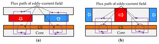
Figure 8.
The flux path of eddy current field of the PMECCs with non-slotted CR: (a) Model-A; (b) Model-C.
The magnetic field excited by PM interacts with that generated by the eddy-current in the CS, so an iterative process needs to be added in the calculation of the air-gap magnetic field in the load state. Assuming there is no magnetic saturation in the cores of PMR and CR, the magnetic potential difference on the core part can be ignored. We substitute (21) into (23), and it can be simplified as:
where
We take the derivative of (25) with respect to θ, and it is simplified as:
By solving the differential Equation (27), the air-gap flux density generated by the eddy current field can be obtained as:
where
where θ0 is
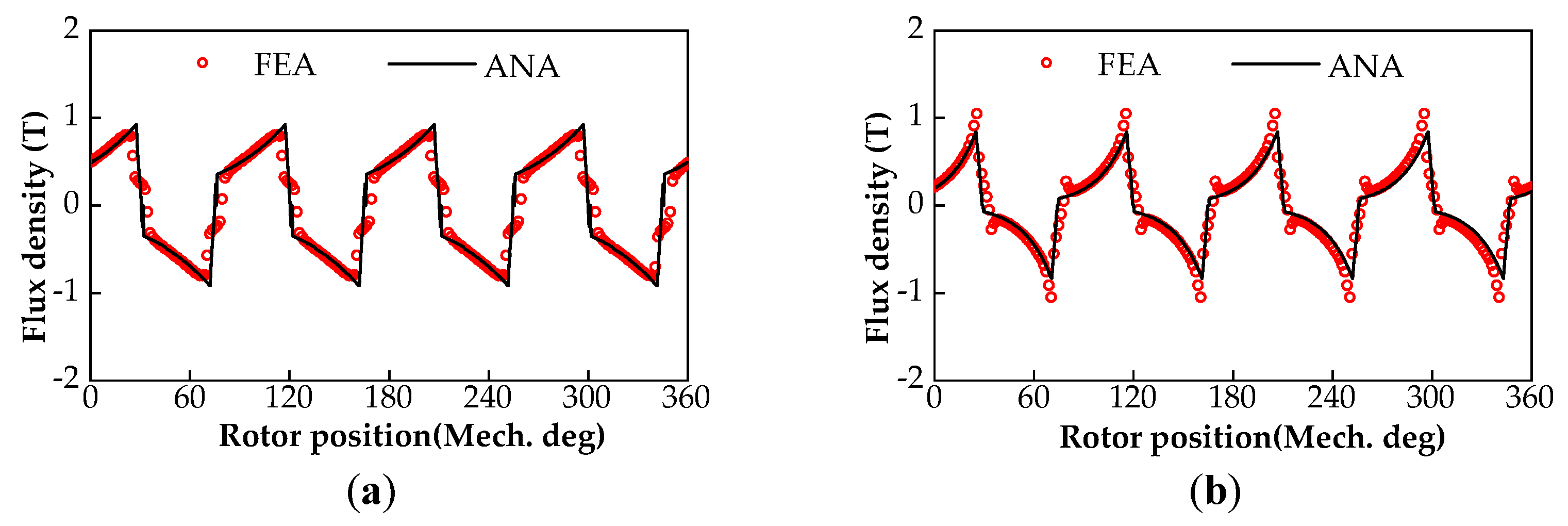
The derivation process of C1, C2, C3 and θ0 have been declared in literature [25]. The air-gap flux density distributions of model−A and model−C are shown in Figure 9. The analytical prediction results are in good agreement with the FEA calculation results, which verifies the reliability of the analytical calculation model of the on-load air-gap magnetic field.

Figure 9.
The on-load air-gap flux density of the PMECCs with non-slotted CR (Slip speed is 250 rpm): (a) Model-A; (b) Model-C.
3.3. On-Load Magnetic Field of Slotted CR
The CR and PMR of a PMECC are usually connected to the output shaft of a prime mover and the input shaft of the pump and fan loads, respectively. The input and output speeds of a PMECC are denoted as ni and no, respectively. Then, the slip frequency between the PMR and the CR can be expressed as:
According to Faraday’s law of electromagnetic induction, the EMF on the conductor bar can be obtained as:
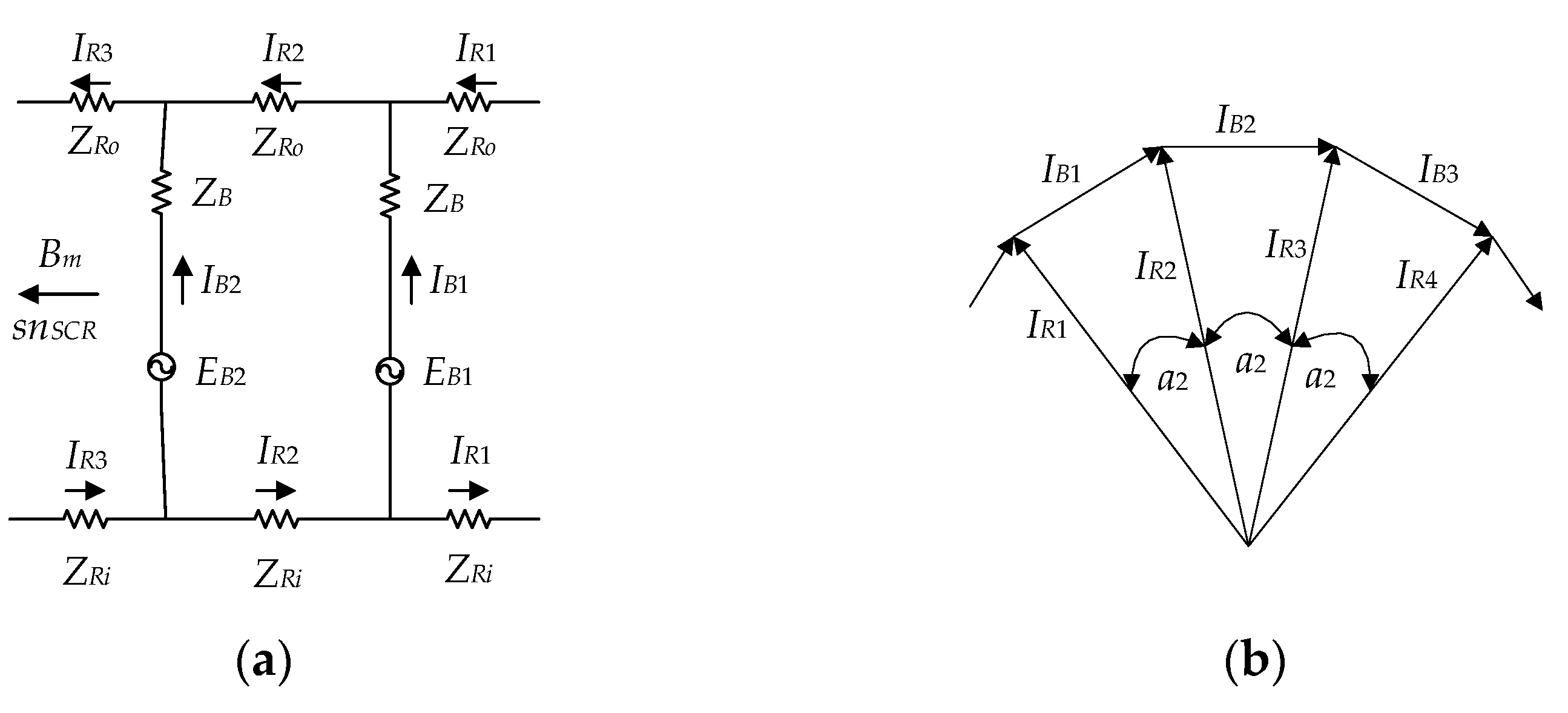
The equivalent circuit model of the slotted CR is shown in Figure 10a. Based on the current vector diagram of the slotted CR as shown in Figure 10b, the relationship between IB and IR can be given as:

Figure 10.
The equivalent circuit model of the PMECC with slotted CR: (a) equivalent circuit; (b) current vector diagram.
Therefore, the copper loss of the whole squirrel cage can be expressed as:
According to the equivalent circuit model shown in Figure 10a, the current of a conductor bar is:
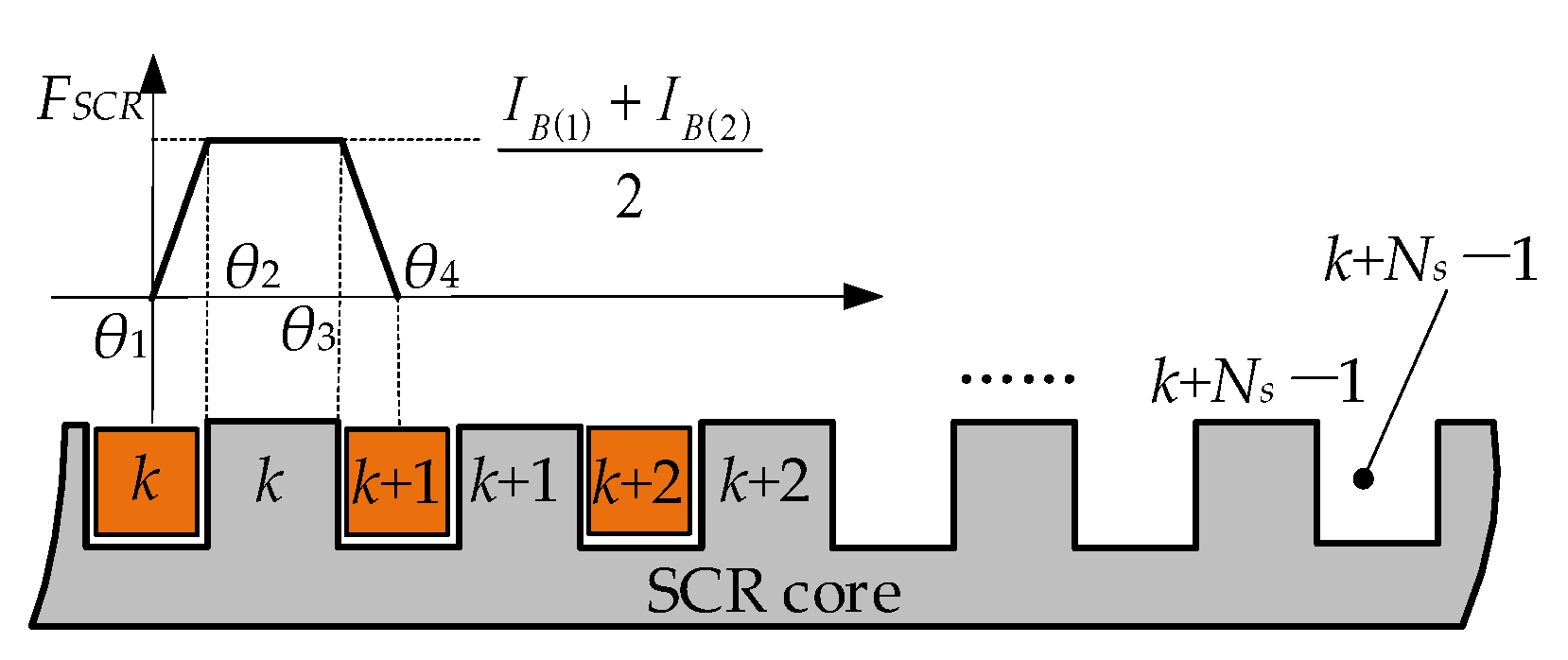
According to the magnetic circuit structure of the slotted CR, the MMF of the slotted CR under on-load state can be established as shown in Figure 11. The MMF on the core tooth is generated by the two adjacent current-carrying conductors, which can be given as:
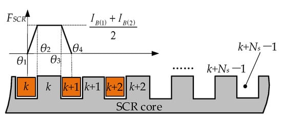
Figure 11.
The MMF model of PMECC with slotted CR under on-load state.
The MMF of the slotted CR generated by the current-carrying conductor can be expressed as:
where
According to the selection principle of eddy current magnetic flux path shown in Figure 8, the permeance required for eddy current magnetic field calculation of SPMECC and IPMECC with slotted CRs are respectively obtained as:
The air-gap flux density generated by slotted CRs of SPMECC and IPMECC under on-load state can be respectively expressed as:
The air-gap flux density of SPMECC and IPMECC with slotted CR under on-load state can be respectively given as:
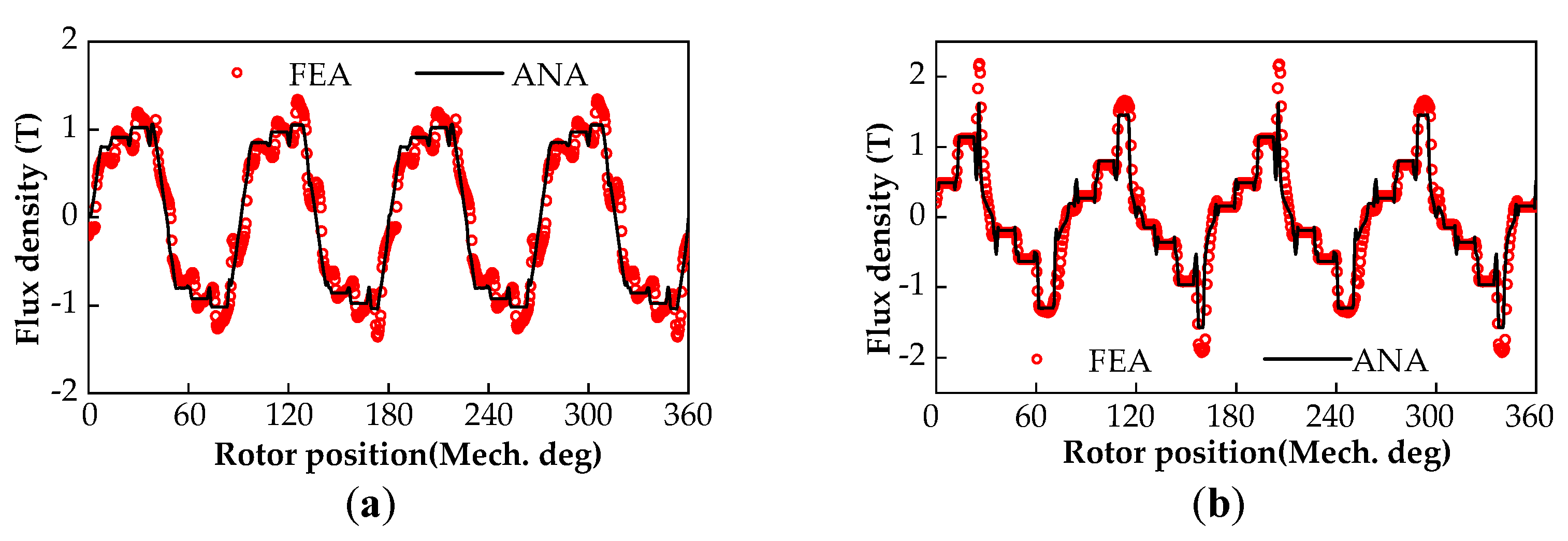
The air-gap flux density distributions of SPMECC and IPMECC with slotted CR are shown in Figure 12. The analytical prediction result is in good agreement with the FEA calculation result, which verifies the reliability of the magnetic field analytical model of the PMECCs with slotted CR under an on-load state.
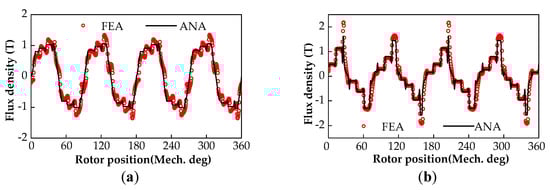
Figure 12.
The on-load air-gap flux density of the PMECC with slotted CR (Slip speed is 250 rpm): (a) Model-B; (b) Model-D.
4. Electromagnetic and Mechanical Performance
4.1. Power and Torque
As a torque transfer device, both the input torque and output torque of PMECC are equal to the load torque TL in a steady state. The input power, output power and slip power of a PMECC can be given, respectively, as:
According to the law of energy conservation, the input mechanical power Pin is mainly transformed into the Pout and Ps. It should be noted that Ps is equal to the copper loss in conductors, and it is emitted in the form of heat energy. Therefore, the electromagnetic torque of PMECC can be obtained by the copper loss in CR and the slip speed Ωs between the CR and PMR of a PMECC. The torques of model−A to D can be obtained, respectively, as:
where pcu_NSCR is the copper loss of non-slotted CR. For a PMECC with non-slotted CR, the eddy current path in the CS includes axial and tangential components. In the two-dimensional analytical model and FEA calculation, only the axial component of the eddy current in the CS is considered, while the tangential component is ignored. Therefore, the Russell coefficient is required to correct the calculation of eddy current loss, which is [26]:
The copper loss in non-slotted CR can be given as:
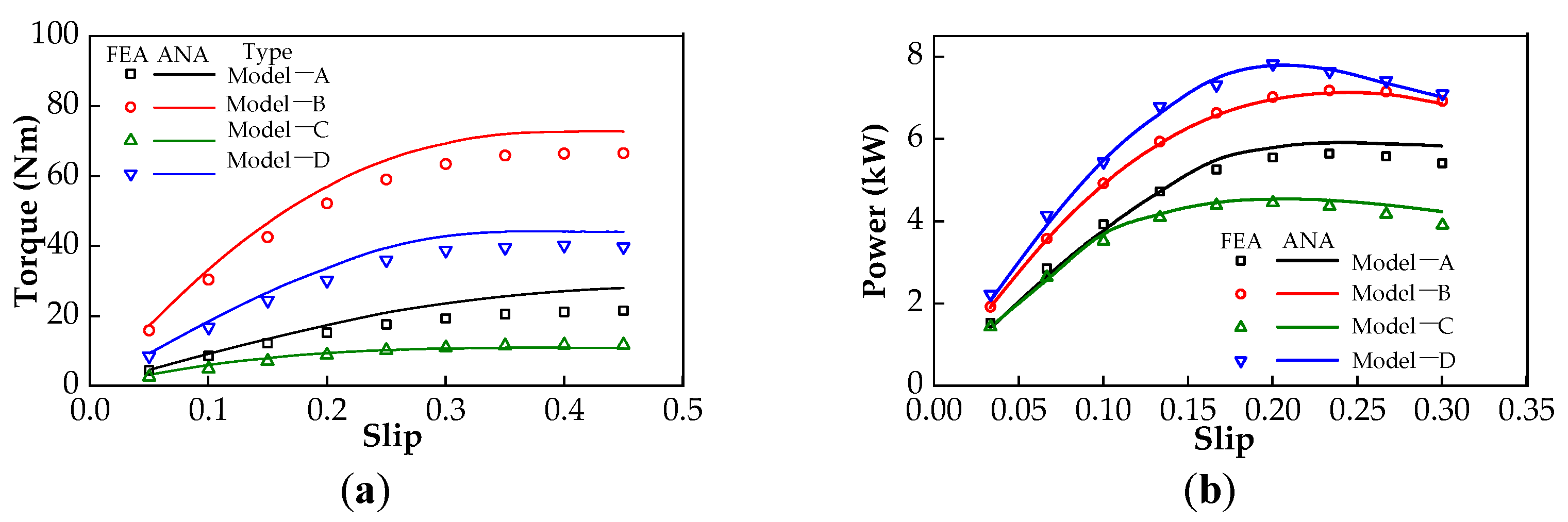
The torque-slip and output power-slip characteristics of the four typical PMECCs are shown in Figure 13a,b, respectively. In addition, the torque of model−A and C are lower than that of model−B and D, respectively, which also proves that the PMECC with slotted CR can obtain higher torque density. With the increase of slip, the output power rises to a maximum value, and then it declines gradually. This is because the torque growth rate slows down and the load speed decreases linearly when the slip increases. Then, the output power shows a downward trend, which is the product of the load speed and the output torque. In addition, the analytical result is slightly larger than the finite element result, which is caused by the factors such as magnetic flux leakage, core saturation and the slot shape being in an analytical model, which is difficult to consider accurately.
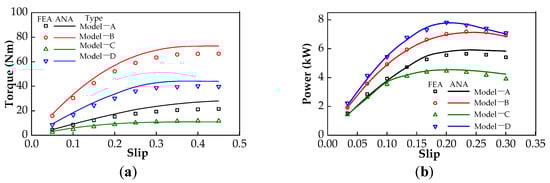
Figure 13.
The output torque and output power of the typical PMECCs: (a) torque-slip characteristics; (b) power-slip characteristics.
4.2. Loss and Efficiency
The losses of a PMECC mainly include core loss, copper loss, mechanical loss and so on. The variable loss of iron consumption pFe is mainly related to the alternating magnetic field and frequency, which can be given as:
The alternating flux excited by PMs mainly passes through the CR core, and the main flux passing through the PMR core is almost a constant flux; the core loss of PMR is generated by a weak eddy current field excited by the CR in an on-load state. Thus, the main iron loss of a PMECC comes from the CR core, and the loss of the PMR can be neglected. The input power of a PMECC is equal to the output power of the prime motor, which is divided into three parts: iron losses, copper losses of CR and output power. Copper loss pcu is also a variable loss, which can be obtained by (34) and (48). Only by taking into account the copper and iron losses can the efficiency of the PMECC be given as:
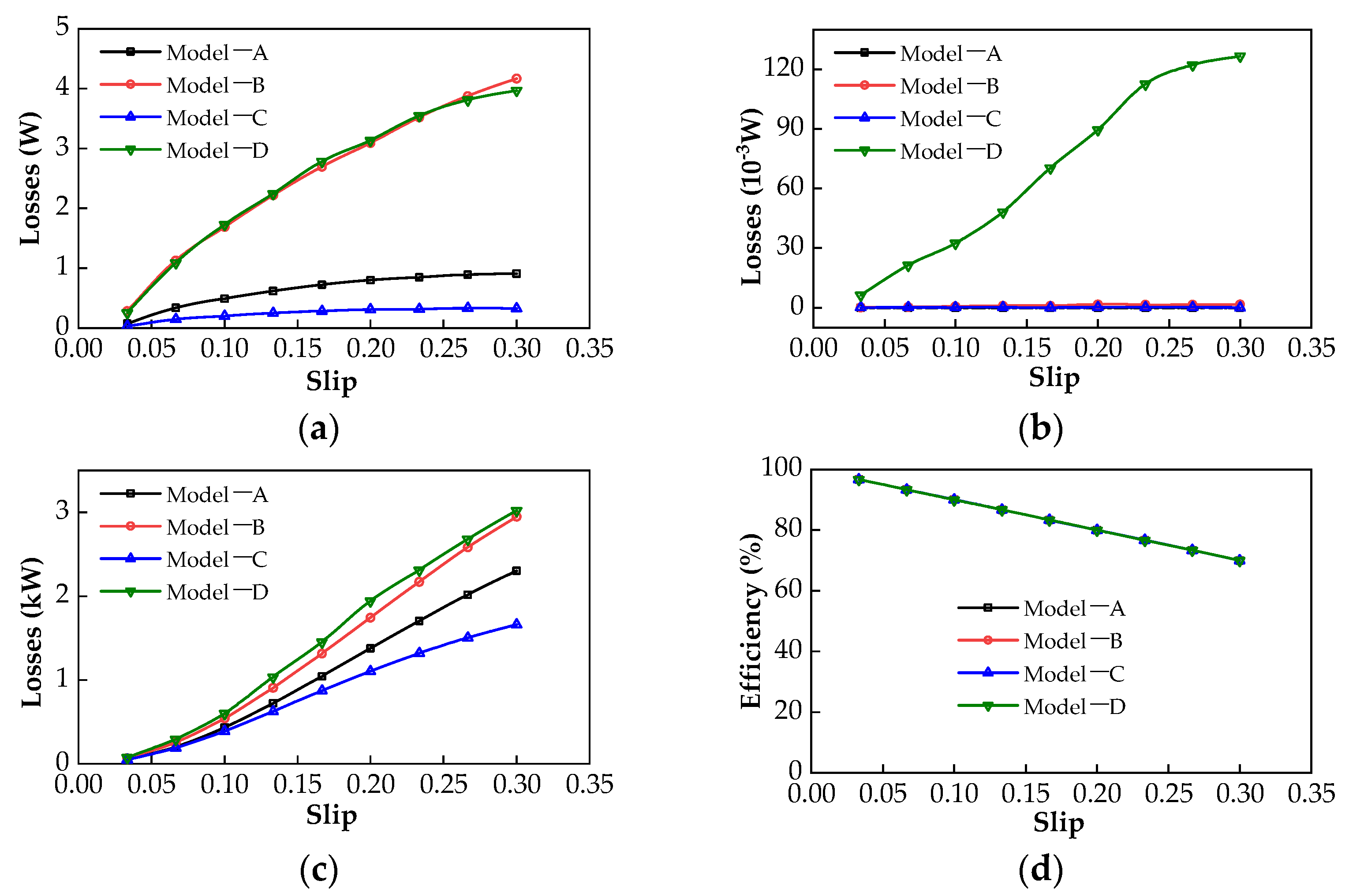
The core losses of the four typical PMECC are shown in Figure 14a,b, respectively. With the increase of slip, the iron losses of CRs increase, in addition, the CR iron losses of model−B and model−D are significantly higher than those of model−A and model−C, respectively. The iron loss of the PMR of model−D is significantly higher than that of the other three structures, which is caused by the stronger alternating magnetic field generated by the eddy current in the slotted CR. As shown in Figure 13b, the maximum output power of the four typical PMECCs is between 4 and 8 kW. The range of iron loss of the PMR is about 0~120 mW, and that of the CR is about 0~4 W. Compared with the PMECC output power as shown in Figure 13b, the iron losses of PMECCs are negligible. The eddy current loss of the conductor, namely copper loss, is shown in Figure 14c. With the increase of slip, the copper loss increases almost linearly. The copper losses of model−B and D are slightly higher than those of model−A and C, and the copper losses of PMECCs with slotted CRs are higher than those of PMECCs with non-slotted CR, which can be explained by the variation of no-load and on-load air-gap flux densities of the four typical PMECCs. The efficiency of the four typical PMECCs mentioned above is shown in Figure 14d. With the increase of slip, the efficiency decreases linearly. Because the copper loss increases gradually with the increase of the slip, iron loss is small enough to have little effect on the efficiency.
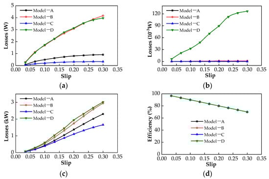
Figure 14.
The losses and efficiencies of typical structure PMECCs: (a) the core losses of CRs; (b) the core losses of PMRs; (c) the eddy current losses of CRs; (d) efficiency.
5. Conclusions
Based on the EMC and the air-gap permeance function methods, the analytical models of the four typical PMECCs were established and summarized in the paper. Then, the analytical prediction results were verified by FEA method.
For a given permanent magnet volume, the air-gap density amplitude mainly depends on the air-gap permeance, and the slotted CR will obtain a much higher power density. For a non-slotted CR structure, the output torque of IPMECC is lower than that of the SPMECC. For a slotted CR structure, the output torque of IPMECC is slightly higher than that of the SPMECC. The iron loss of a PMECC mainly exists in the CR, while the iron loss in PMR is relatively small enough to be ignored in performance prediction. Compared with the output power of a PMECC, the total iron loss of a PMECC is relatively small enough, which can be ignored. Thus, the efficiency of PMECCs mainly depends on the copper losses of CRs, and it decreases linearly with the increase of slip.
The analytical prediction results are in good agreement with the FEA results. The analytical model can be used to predict the basic electromagnetic characteristics of PMECCs efficiently. Simultaneously, it also improves the initial design efficiency and the in-depth analysis of the electromechanical energy conversion mechanism of PMECCs.
Author Contributions
Conceptualization: Y.L. (Yibo Li); Data curation: F.G. and Y.L. (Yao Li); Formal analysis: F.G., Q.S. and D.Z.; Funding acquisition: Y.L. (Yibo Li), J.H., F.G., Z.Z. and Y.H.; Investigation: Y.L. (Yibo Li); Methodology: Y.L. (Yibo Li), J.H. and Z.Z.; Project administration: Y.L. (Yibo Li); Resources: J.H. and Z.Z.; Software: Y.H. and Y.L. (Yao Li); Visualization: J.H.; Writing—original draft: Y.L. (Yibo Li); Writing—review and editing: Y.L. (Yibo Li) All authors have read and agreed to the published version of the manuscript.
Funding
National Natural Science Foundation of China (Grant No. 52107048; 51977103; 51877101), Basic science (natural science) research project of colleges and universities of Jiangsu Province (Grant No. 21KJB470021; 20KJA510007) and the Scientific Research Foundation for the High-level Personnel of Nanjing Institute of Technology (Grant No. YKJ2019107; YKJ2019106; YKJ2019109; YKJ202042).
Institutional Review Board Statement
Not applicable.
Informed Consent Statement
Not applicable.
Data Availability Statement
Not applicable.
Acknowledgments
Thanks to the support of the completed National Natural Science Foundation of China (Grant No. 51577026); Thanks to Heyun Lin (School of Electrical Engineering, Southeast University, Nanjing, China) for his supervision during the doctoral research career of Yibo Li.
Conflicts of Interest
The authors declare no conflict of interest.
Nomenclature
| PMECC | permanent magnet eddy current coupler |
| SPM | surface-mounted PM |
| IPM | interior PM |
| PMR | PM rotor |
| CR | conductor rotor |
| SPMR | SPM rotor |
| IPMR | IPM rotor |
| CS | conductor sheet |
| MMF | magnetomotive force |
| EMF | electromotive force |
| EMC | equivalent magnetic circuit |
| FEA | finite element analysis |
| Model-A | PMECC with SPMR and non-slotted CR |
| Model-B | PMECC with SPMR and slotted CR |
| Model-C | PMECC with IPMR and non-slotted CR |
| Model-D | PMECC with IPMR and slotted CR |
| NS | subscript of parameters relative to Model-A |
| SS | subscript of parameters relative to Model-B |
| NI | subscript of parameters relative to Model-C |
| SI | subscript of parameters relative to Model-D |
| Bg(θ) | air-gap flux density distribution |
| Bgm | amplitude of no-load air-gap flux density |
| Br(θ) | radial component of air-gap flux density |
| FPM(θ) | inner air-gap MMF |
| Λ(θ) | air-gap permeance |
| FPMm | amplitude of FPM(θ) |
| τp | pole pitch of PMR in radian |
| Hc | PM coercivity |
| RCS | reluctance of copper sheet |
| Rg | reluctance of air-gap |
| RSPM | reluctance of SPM |
| RIPM | reluctance of IPM |
| Rend | reluctance of flux leakage at outer radius of IPM |
| hCS | thickness of CS |
| hSPM | thickness of SPM along magnetization direction |
| hIPM | thickness of IPM along magnetization direction |
| lg | length of air-gap |
| L | axial length of PM |
| rIPMo | outer radius of IPM rotor |
| rIPMi | inner radius of IPM rotor |
| rSPMo | outer radius of SPM rotor |
| rSPMi | inner radius of SPM rotor |
| rCSi | inner radius of CS |
| rCSo | outer radius of CS |
| rCRo | outer radius of slotted CR |
| rs | center radius of slot |
| rav | average radius of CS |
| α2 | electrical angle between two adjacent conductor bars |
| Rb | resistance of conductor bar in CR |
| RR | phase resistance of cage end ring, |
| Rb+R | equivalent phase resistance of cage. |
| Xb+R | equivalent phase reactance of slotted structure CR |
| p | number of pole-pairs |
| θm | half of PM width in radian |
| δSPM (θ) | additional air-gap corresponding to equivalent length of SPMR |
| δIPM (θ) | additional air-gap corresponding to equivalent length of IPMR |
| δSCR(θ) | additional air-gap corresponding to equivalent length of slotted CR |
| δNSCR(θ) | additional air-gap corresponding to equivalent length of non-slotted CR |
| φ | phase difference between EMF and current of same conductor bar |
| θs | slot pitch of slotted CR in radian |
| βs | ratio of slot width and slot pitch |
| k,n | positive integer |
| Ωin | input speed of PMECC (rad/s) |
| Ωout | output speed of PMECC (rad/s) |
| Ωs | slip speed (rad/s) |
| wm | radial length of IPM |
| Br | PM remanence |
| μr | relative permeance of PM |
| Ns | slot numbers of slotted CR |
| σ | copper conductivity (75 °C) |
| μ0 | vacuum permeability (4π×10−7 H/m) |
| αm | pole-arc coefficient of PMR |
| Cfe | iron consumption coefficient |
| B | magnetic density of iron core |
| G | quality of rotor iron core |
| IB | effective phase current of conductor bar |
| IR | effective phase current of end ring |
Appendix A
The main design parameters of the four typical PMECCs are listed in Table A1.

Table A1.
The main design parameters of the four typical PMECCs.
Table A1.
The main design parameters of the four typical PMECCs.
| Structural Parameters | Model-A | Model-B | Model-C | Model-D |
|---|---|---|---|---|
| rCRo | 50 mm | 50 mm | 50 mm | 50 mm |
| hCS | 3 mm | -- | 3 mm | -- |
| σ | 5.77 × 10⁷ S/m | 5.77 × 10⁷ S/m | 5.77 × 10⁷ S/m | 5.77 × 10⁷ S/m |
| loh | 5 mm | -- | 5 mm | -- |
| hCRc | 10 mm | 20 mm | 10 mm | 20 mm |
| hSPMRc | 10 mm | 10 mm | -- | -- |
| hIPMRc | -- | -- | 27.5 mm | 27.5 mm |
| lg | 1 mm | 1 mm | 1 mm | 1 mm |
| rPMRi | 51 mm | 51 mm | 51 mm | 51 mm |
| hSPM | 6 mm | 6 mm | -- | -- |
| hIPM | -- | -- | 8 mm | 8 mm |
| SPM | 203.6 mm2 | 203.6 mm2 | 203.6 mm2 | 203.6 mm2 |
| L | 50 mm | 50 mm | 50 mm | 50 mm |
| Hc | −890 kA/m | −890 kA/m | −890 kA/m | −890 kA/m |
| p | 4 | 4 | 4 | 4 |
| αm | 0.80 | 0.80 | 0.80 | 0.80 |
| rslot | -- | 2.5 mm | -- | 2.5 mm |
| Ns | -- | 30 | -- | 30 |
References
- Davies, E. An Experimental and Theoretical Study of Eddy-Current Couplings and Brakes. IEEE Trans. Power Appar. Syst. 1963, 82, 401–419. [Google Scholar] [CrossRef]
- Canova, A.; Vusini, B. Design of axial eddy-current couplers. IEEE Trans. Ind. Appl. 2003, 39, 725–733. [Google Scholar] [CrossRef]
- Lubin, T.; Rezzoug, A. Steady-State and Transient Performance of Axial-Field Eddy-Current Coupling. IEEE Trans. Ind. Electron. 2014, 62, 2287–2296. [Google Scholar] [CrossRef] [Green Version]
- Sharif, S.; Faiz, J.; Sharif, K. Performance analysis of a cylindrical eddy current brake. IET Electr. Power Appl. 2012, 6, 661–668. [Google Scholar] [CrossRef]
- Yazdanpanah, R.; Mirsalim, M. Axial-flux wound-excitation eddy current brakes: Analytical study and parametric modeling. IEEE Trans. Magn. 2014, 50, 1–10. [Google Scholar] [CrossRef]
- Mohammadi, S.; Mirsalim, M.; Vaez-Zadeh, S.; Talebi, H.A. Analytical Modeling and Analysis of Axial-Flux Interior Permanent-Magnet Couplers. IEEE Trans. Ind. Electron. 2014, 61, 5940–5947. [Google Scholar] [CrossRef]
- Dai, X.; Liang, Q.; Cao, J.; Long, Y.; Mo, J.; Wang, S. Analytical Modeling of Axial-Flux Permanent Magnet Eddy Current Couplings with a Slotted Conductor Topology. IEEE Trans. Magn. 2015, 52, 1–15. [Google Scholar] [CrossRef]
- Canova, A.; Freschi, F.; Gruosso, G.; Vusini, B. Genetic optimisation of radial eddy current couplings. COMPEL Int. J. Comput. Math. Electr. Electron. Eng. 2005, 24, 767–783. [Google Scholar] [CrossRef]
- Lubin, T.; Rezzoug, A. Improved 3-D Analytical Model for Axial-Flux Eddy-Current Couplings with Curvature Effects. IEEE Trans. Magn. 2017, 53, 1–9. [Google Scholar] [CrossRef]
- Mohammadi, S.; Mirsalim, M.; Vaez-Zadeh, S. Nonlinear Modeling of Eddy-Current Couplers. IEEE Trans. Energy Convers. 2013, 29, 224–231. [Google Scholar] [CrossRef]
- Mohammadi, S.; Mirsalim, M. Double-sided permanent-magnet radial-flux eddy current couplers: Three-dimensional analytical modelling, static and transient study, and sensitivity analysis. IET Electr. Power Appl. 2013, 7, 665–679. [Google Scholar] [CrossRef]
- Mohammadi, S.; Mirsalim, M.; Niazazari, M.; Talebi, H.A. A new interior permanent-magnet radial-flux eddy-current coupler. In Proceedings of the 5th Annual International Power Electronics, Drive Systems and Technologies Conference (PEDSTC 2014), Tehran, Iran, 5–6 February 2014; pp. 500–505. [Google Scholar] [CrossRef]
- Wang, J.; Lin, H.; Fang, S.; Huang, Y. A General Analytical Model of Permanent Magnet Eddy Current Couplings. IEEE Trans. Magn. 2013, 50, 1–9. [Google Scholar] [CrossRef]
- Zhang, H.; Wang, D.; Wang, X.; Wang, X. Equivalent Circuit Model of Eddy Current Device. IEEE Trans. Magn. 2018, 54, 1–9. [Google Scholar] [CrossRef]
- Wang, J.; Zhu, J. A Simple Method for Performance Prediction of Permanent Magnet Eddy Current Couplings Using a New Magnetic Equivalent Circuit Model. IEEE Trans. Ind. Electron. 2017, 65, 2487–2495. [Google Scholar] [CrossRef]
- Li, Y.; Lin, H.; Yang, H. A novel squirrel-cage rotor permanent magnet adjustable speed drive with a non-rotary mechanical flux adjuster. IEEE Trans. Energy Convers 2021, 36, 1036–1044. [Google Scholar] [CrossRef]
- Yang, X.; Liu, Y.; Wang, L. Nonlinear Modeling of Transmission Performance for Permanent Magnet Eddy Current Coupler. Math. Probl. Eng. 2019, 2019, 1–14. [Google Scholar] [CrossRef]
- Gaussens, B.; Hoang, E.; de la Barriere, O.; Saint-Michel, J.; Lecrivain, M.; Gabsi, M. Analytical approach for air-gap modeling of field-excited flux-switching machine: No-load operation. IEEE Trans. Magn. 2012, 48, 2505–2517. [Google Scholar] [CrossRef] [Green Version]
- Gaussens, B.; Hoang, E.; de la Barriere, O.; Saint-Michel, J.; Manfe, P.; Lécrivain, M.; Gabsi, M. Analytical armature reaction field prediction in field-excited flux-switching machines using an exact relative permeance function. IEEE Trans. Magn. 2013, 49, 628–641. [Google Scholar] [CrossRef]
- Gibbs, W.J. Conformal Transformations in Electrical Engineering; Chapman & Hall: London, UK, 1958. [Google Scholar]
- Zarko, D.; Ban, D.; Lipo, T.A. Analytical calculation of magnetic field distribution in the slotted air-gap of a surface permanent-magnet motor using complex relative air-gap permeance. IEEE Trans. Magn. 2006, 42, 1828–1837. [Google Scholar] [CrossRef]
- Žarko, D.; Ban, D.; Lipo, T.A. Analytical Solution for Cogging Torque in Surface Permanent-Magnet Motors Using Conformal Mapping. IEEE Trans. Magn. 2007, 44, 52–65. [Google Scholar] [CrossRef]
- Hamata, V.; Heller, B. Harmonic Field Effects in Induction Machines; Elsevier: Amsterdam, The Netherlands, 1977. [Google Scholar]
- Zhu, Z.; Howe, D. Instantaneous magnetic field distribution in brushless permanent magnet DC motors. III. Effect of stator slotting. IEEE Trans. Magn. 1993, 29, 143–151. [Google Scholar] [CrossRef]
- Li, Y.; Lin, H.; Tao, Q.; Lu, X.; Yang, H.; Fang, S.; Wang, H. Analytical analysis of an adjustable-speed permanent magnet eddy-current coupling with a non-rotary mechanical flux adjuster. IEEE Trans. Magn. 2019, 55, 1–5. [Google Scholar] [CrossRef]
- Russell, R.L.; Norsworthy, K.H. Eddy currents and wall losses in screened-rotor induction motors. Proc. IEE-Part A Power Eng. 1958, 105, 163–175. [Google Scholar] [CrossRef]


Publisher’s Note: MDPI stays neutral with regard to jurisdictional claims in published maps and institutional affiliations. |
© 2021 by the authors. Licensee MDPI, Basel, Switzerland. This article is an open access article distributed under the terms and conditions of the Creative Commons Attribution (CC BY) license (https://creativecommons.org/licenses/by/4.0/).