Article

Reduced-Order-VSM-Based Frequency Controller for Wind Turbines

Department of Wind Energy, Technical University of Denmark, Frederiksborgvej 399, 4000 Roskilde, Denmark
*
Author to whom correspondence should be addressed.
Energies 2021, 14(3), 528; https://doi.org/10.3390/en14030528
Submission received: 21 December 2020 / Revised: 13 January 2021 / Accepted: 18 January 2021 / Published: 20 January 2021
(This article belongs to the Section A3: Wind, Wave and Tidal Energy)

Abstract

:
Frequency support capability is becoming an important requirement for wind turbines, as wind power is increasingly integrated into power systems. In this paper, a frequency controller is implemented and validated. Such a controller allows wind turbines to help regulate the system frequency automatically and includes virtual inertia to help limit the rate of change of frequency. Compared with other methods, the controller achieves satisfactory frequency support capability with considerable simplicity. The controller is added to the grid-side converter controls, together with cascaded inner loops, which enables wind turbines to operate in grid-forming mode with overcurrent protection. The influence of the controller parameters on the frequency response is investigated.

1. Introduction

Wind energy is playing an increasingly important role in power systems. The total installed capacity of wind power has already surpassed 205 GW in Europe, and wind energy provided 15% of the electricity consumption in the EU countries in 2019 [1]. As more inverter-based-resources (IBR) is integrated into power systems and traditional generation units are decommissioned, the total inertia of the power system is decreasing [2,3,4]. As inertia plays an important role in limiting the rate of change of frequency (RoCoF) during frequency events, it is becoming more challenging to ensure power system frequency stability. Reduced inertia can result in larger RoCoF, which can cause generation to disconnect [5]. Generators will have to comply with stricter grid code requirements on the RoCoF withstand capability [6,7]. Lower inertia also contributes to lower frequency nadirs during underfrequency events, which may trigger undesirable underfrequency load shedding [8]. This issue needs to be carefully addressed in power systems with increasing IBR.
One method of limiting the RoCoF in such systems during frequency events is having IBR respond to such events by manipulating their production in proportion to the RoCoF [9]. Such a method usually relies on PLLs to estimate the frequency from local voltage measurements, before its rate of change can be calculated. An additional torque or active power signal, proportional to the estimated RoCoF, is added to the original reference. In this way, additional active power is provided by a wind turbine (WT) to support the frequency during an underfrequency event.
However, a disadvantage of this method comes from the estimation of frequency and its rate of change. Firstly, considerable time lag is accumulated in the process, from sampling, filtering, and digital signal processing. Such a time lag, usually ranging from 0.5 to 1 s [6], degrades the inertial response and fast frequency regulation, which take place within the first few seconds (typically 5–10 s). Secondly, calculation of the derivative of frequency typically induces noise to the control system, which may lead to instability. Removing such noise by processing the resulting signal can also result in further time lag.
Furthermore, aforementioned problems of frequency estimation become even more prominent in weak grids because of distorted voltage measurements [10,11]. This method operates an RES as a current source, while operating multiple current sources is prone to lead to instability [12]. This is also termed as grid-following control. Challenges can also arise for synchronization of grid-following control in weak grids where voltages are distorted. The synchronization instability can lead to sideband oscillations in voltages and currents [13]. Moreover, an RES in the grid-following control mode cannot operate as the only power source in an islanded or isolated microgrid, in which a grid-forming power source is needed.
A second-order-model implementation of the virtual synchronous machine (VSM) control concept can provide the grid-forming control mode and virtual inertial response simultaneously. Generally, VSMs are control schemes applied to converters, which can allow IBR to emulate the behavior of conventional power plants.
Until now, several VSM control schemes have been proposed. Most of them are trying to include the synchronous machines’ (SMs’) model as much as possible, like a complete SM model in the first proposal [14] or a fifth-order SM model without rotor damper windings in [15]. This is an intuitive direction to work towards at the early stage of this concept. However, this not only obtains the desired characteristics for frequency control from a conventional power plant, but also brings complexity by including the detailed electromagnetic interactions from an SM. The more complex this nonlinear system is, the more difficult implementation will be, and numerical instability might also be a problem. In such a manner, undesired properties of an SM, like a loss of stability or subsynchronous oscillations, may also occur in a VSM-controlled system [15]. In addition, the concept of VSM control was first widely discussed for microgrid applications. Hence most schemes also contain a reactive power control block [16,17]. However, this block is likely to cause power coupling issues or power ripples depending on the gain [18].
In this paper, focus is given to frequency support capability from WTs. A frequency controller is proposed, which has a simplified emulation of a conventional power plant for satisfactory frequency support capability. Only the swing equation and frequency-active power (f-P) droop control are implemented and in the swing equation, only the inertia constant is included, to regulate the virtual inertial response at the beginning of a frequency event. The frequency controller is added to the grid-side converter (GSC) control, together with cascaded inner loops. The influence of the controller parameters (inertia constant and droop coefficient) on the frequency response is investigated in detail.
The rest of the paper is organized as follows. Section 2 describes the proposed frequency controller (FC) and GSC control scheme. Influence of the inertia constant and droop coefficient in the FC on the frequency response of the GSC is illustrated in Section 3, before concluding in Section 4.

2. Modeling and Control of the GSC

The GSC control scheme comprises an internal current feedback loop. For this loop, a synchronous vector controller is used, with two PI compensators of current vector components defined in rotating synchronous coordinates dq. With this controller, it is easy to perform the open-loop test of the inverter and achieve ideally impressed currents, which improves the power quality [19].
The current loop is tuned using the loop shaping method for a bandwidth of 200 Hz. The outer of it is a voltage loop. Both of them use classical configurations [20].
The voltage loop is tuned using the symmetrical optimum method so that the resulting closed-loop system has a triple real pole (and a phase margin of approximately 53°, as a consequence). To eliminate overshoot caused by the lead terms in the PI controllers, lag terms are introduced into the scheme via first-order low-pass prefiltering of the reference voltage v f _ d q * . With such prefiltering, the voltage loop bandwidth is reduced to about 34 Hz.
An active damping term is added to the converter voltage reference v c _ d q * for suppressing LC oscillations in the converter filter [21,22].

Frequency Controller

In this work, consideration is given solely to primary frequency control (PFC) for the frequency support capability. The proposed frequency controller (FC) provides two different functions for frequency support: virtual inertia and droop control. This simplicity helps to maintain the advantages of converter control, like flexibility and rapidity. The frequency controller (FC) emulates the swing equation for virtual inertial response and includes f-P droop control for primary frequency control (PFC).
The dynamic equation of rotational motion of an SM (1), commonly referred to as the swing equation, describes the swings in rotor angle caused by unbalances between the electromagnetic (air-gap) torque and the mechanical input torque in an SM. The torque imbalance causes the rotor to accelerate or decelerate. This changes the relative angle between the electromotive force created by the magnetic field in the rotor of the SM and the terminal voltage in the stator. Variation of this angle difference results in a variation of electromagnetic torque according to the power–angle relationship.
The swing equation can be written as [23]
2 H ω n d 2 δ d t 2 = T m T e
where
  • H = inertia constant in MW·s/MVA;
  • ω n = rated angular velocity in electrical rad/s;
  • δ = angular position in electrical radians;
  • t = time in s;
  • T m = mechanical torque in per unit (pu);
  • T e = electromagnetic torque in per unit (pu).
For analyzing its dynamics, it is expressed in the state-space form, becoming
d Δ ω r d t = 1 2 H ( T m T e )
d δ d t = ω n Δ ω r
where
  • ω r = angular velocity in electrical rad/s;
  • Δ ω r = deviation of angular velocity in pu
  • = ( ω r ω n ) / ω n .
The emulation of swing equation plays a critical role in the FC. In the scheme, the aforementioned power angle δ becomes a control target, which is obtained from integration of virtual rotating speed ω, obtained as the output of (2), with the power imbalance as input. The power imbalance is the deviation of active power measured at the point of connection (PoC) from the power reference.
From (2) it is easy to get that a large inertia (reflected by the value of H) is beneficial to limit the value of d Δ ω r / d t , for a certain torque imbalance ( T m T e ) . The value of d Δ ω r / d t is equivalent to RoCoF, which is one of the two key metrics for evaluating the performance of frequency support capability. This is how conventional power plants help to maintain the frequency stability by avoiding a large RoCoF because of the coupling between SMs’ rotating speed and system frequency. By emulating the swing equation in the FC, the power source shows the same inertial response as a conventional power plant in a frequency event. The RoCoF thereby is limited by the virtual inertia. This is how this FC helps to maintain the same frequency stability of a power system even with more and more IBR being integrated.
The inertia constant H has a relatively small range of variation in terms of different types of conventional power plants, typically in the range of 2–10 [23]. It is determined by their type and size.
However, for the FC, its virtual inertia constant is a control parameter that can be manipulated. This becomes an advantage for virtual inertial response in frequency support. The inertia constant can also be adjusted in real time to achieve a faster and more stable operation. Different values (even negative) can be used in different phases of oscillations (acceleration or deceleration) to achieve a better damping of oscillations [24,25].
The governor with a speed-droop characteristic in a conventional power plant is characterized as a proportional controller with a gain of 1 / D r .
The parameter D r , referred to as speed regulation or droop coefficient, determines the steady-state speed versus load characteristic of an SM and its prime mover. It is equal to the ratio of speed deviation (∆ω) or frequency deviation (∆f) to change in active power output (∆P) or torque output (∆T). In this paper, the parameters in our control scheme are all in per unit.
The governor regulates the mechanical power input of the prime mover according to the change of grid frequency and brings the frequency back to a new steady state in the PFC process. This is the second role, apart from inertial response, that conventional power plants play in maintaining the frequency stability. The frequency deviation is mainly determined by the value of power imbalance and is essentially reduced by reducing the power imbalance between generation and load. There are two key metrics for evaluating the performance of frequency support capability: RoCoF and extremum (nadir or zenith) of frequency. As discussed before, RoCoF in the inertial response process is mainly determined by the inertia constant. Extremum of frequency in the whole PFC process is mainly influenced by the droop coefficient.
The GSC control scheme is shown in Figure 1.

3. Simulation Results

Dynamic simulations were performed to verify the feasibility of the GSC control scheme. The influence of the two FC parameters on the frequency response was also investigated. RoCoF and frequency nadir were calculated to assess the performance of the controls during an underfrequency event.
The power system simulated is shown in Figure 2. The model is implemented in MATLAB Simulink. In this system, a GSC is connected to a synchronous generator (SG) and a load via a line with resistance R l and inductance L l . An underfrequency event was simulated at t = 8   s by means of a 0.2 pu load increase. The parameters for the GSC, SG, and line are given in Table A1, Table A2 and Table A3 in the Appendix A.
For the SG, the delay in an SG frequency response depends on the types of governor and turbine. In this paper, the delays in the SG (representing time lags of the governor and the steam turbine) are linearly represented by first-order transfer functions, appropriate for load-frequency analysis. The governor time constant T g has a typical value of 0.2 s, resulting in a delay of 3–5 s [23].
For the GSC, we used an average model, therefore omitted PWM.
The electric circuits of the model are in physical units, while the GSC control scheme is in per unit. The base power is defined from the total apparent power rating of the SG or GSC. The base voltage is the peak value of rated phase-to-ground voltage. Transformation from abc to dq frame is based on the amplitude-invariant Park transformation [23].

3.1. Influence on Dynamic Response

The influence of the FC’s inertia constant and droop coefficient on the system’s dynamic response was investigated by performing a parametric sensitivity analysis. The dynamic response of the relevant variables was plotted for different parameter values to assess its influence.
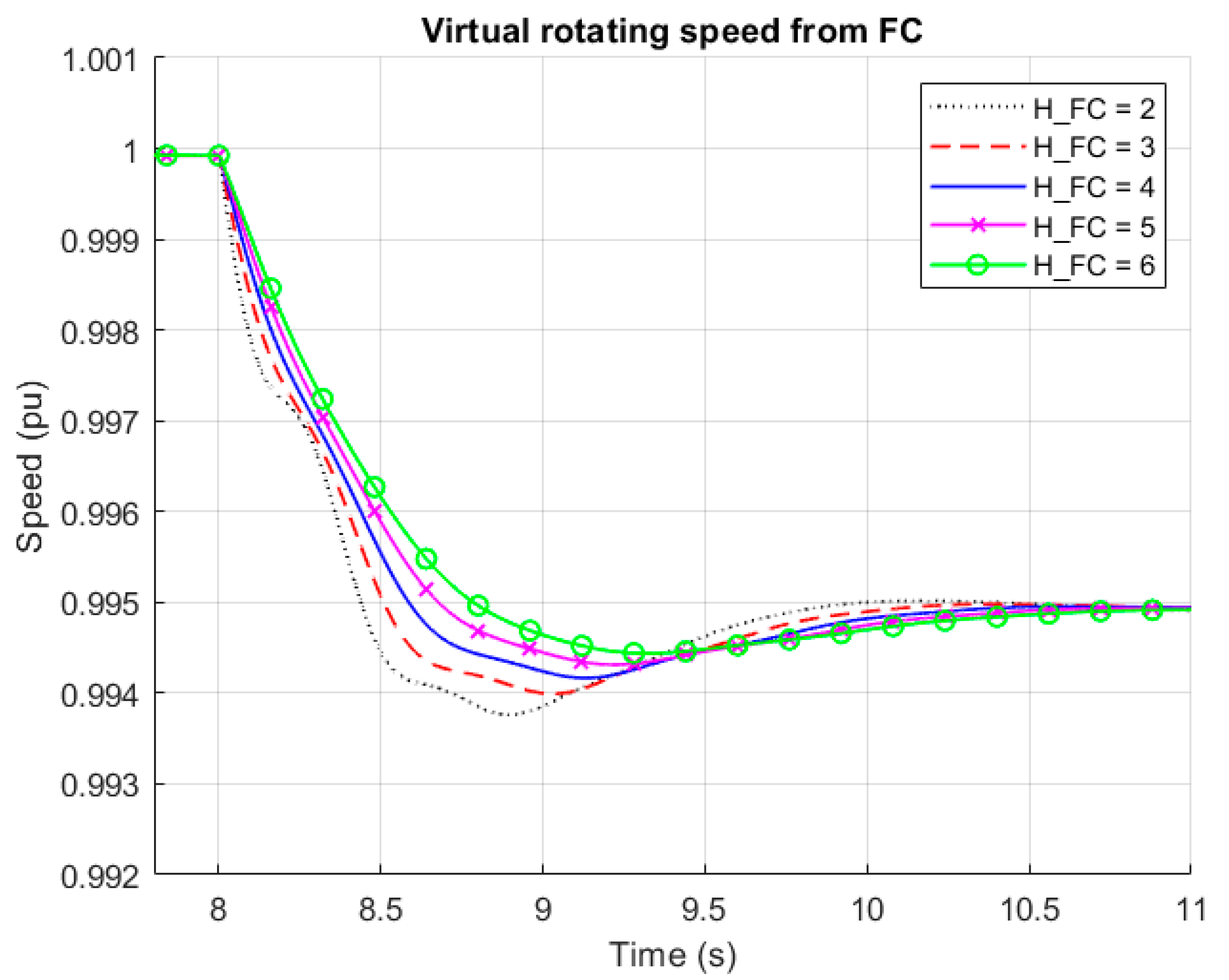
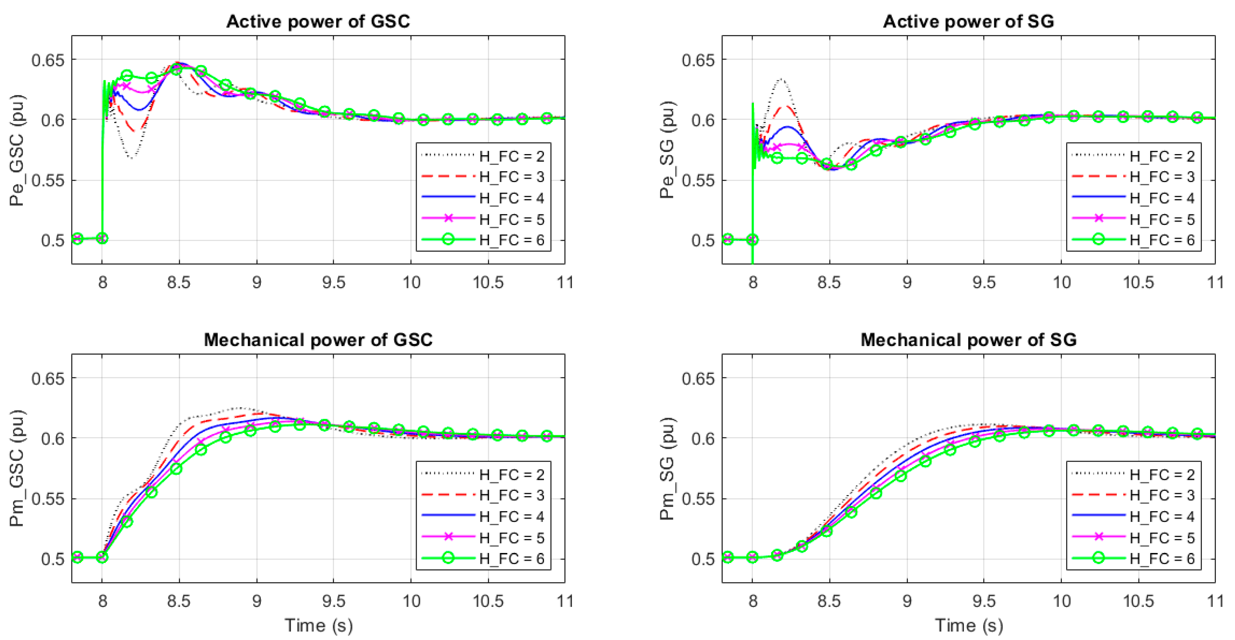
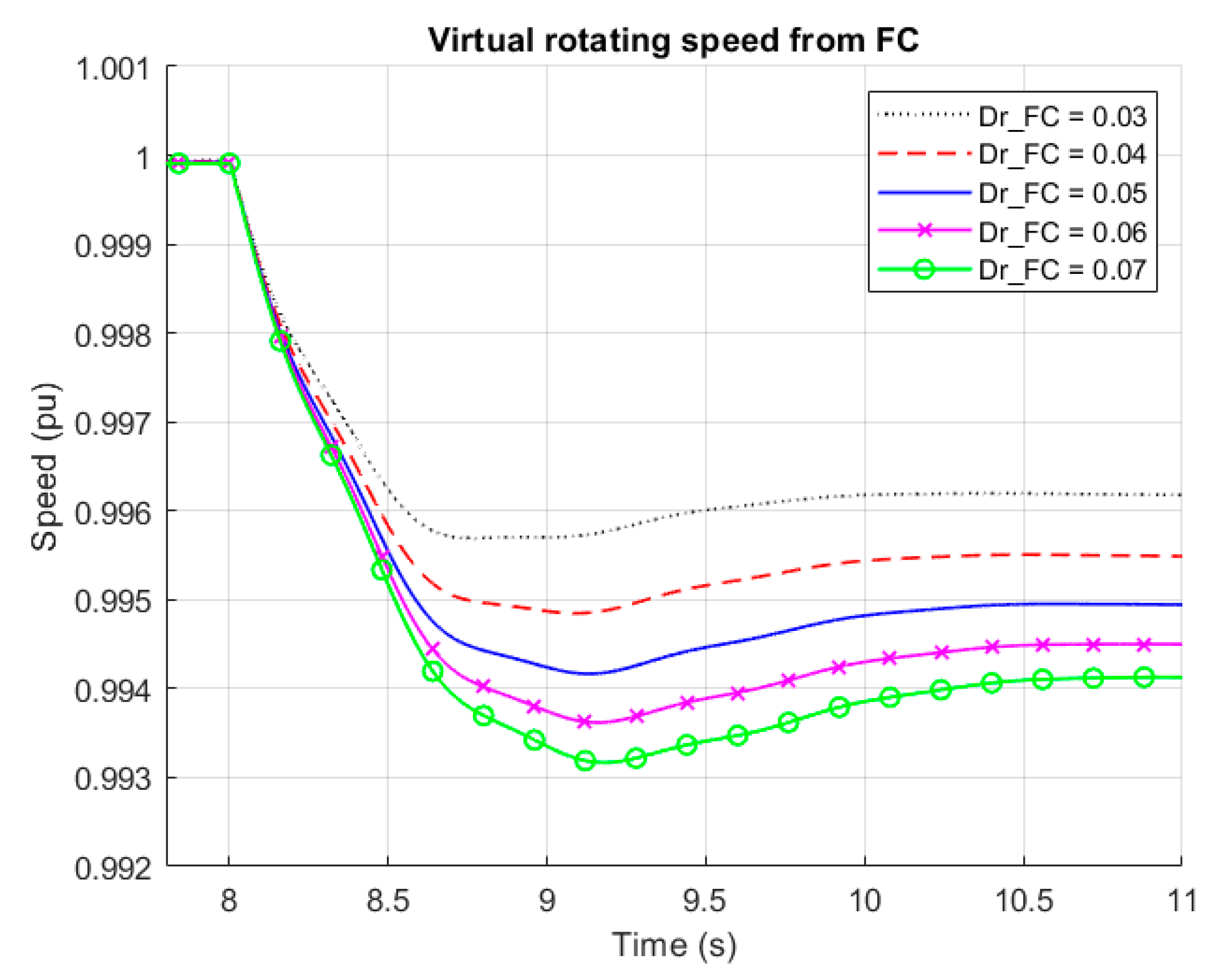
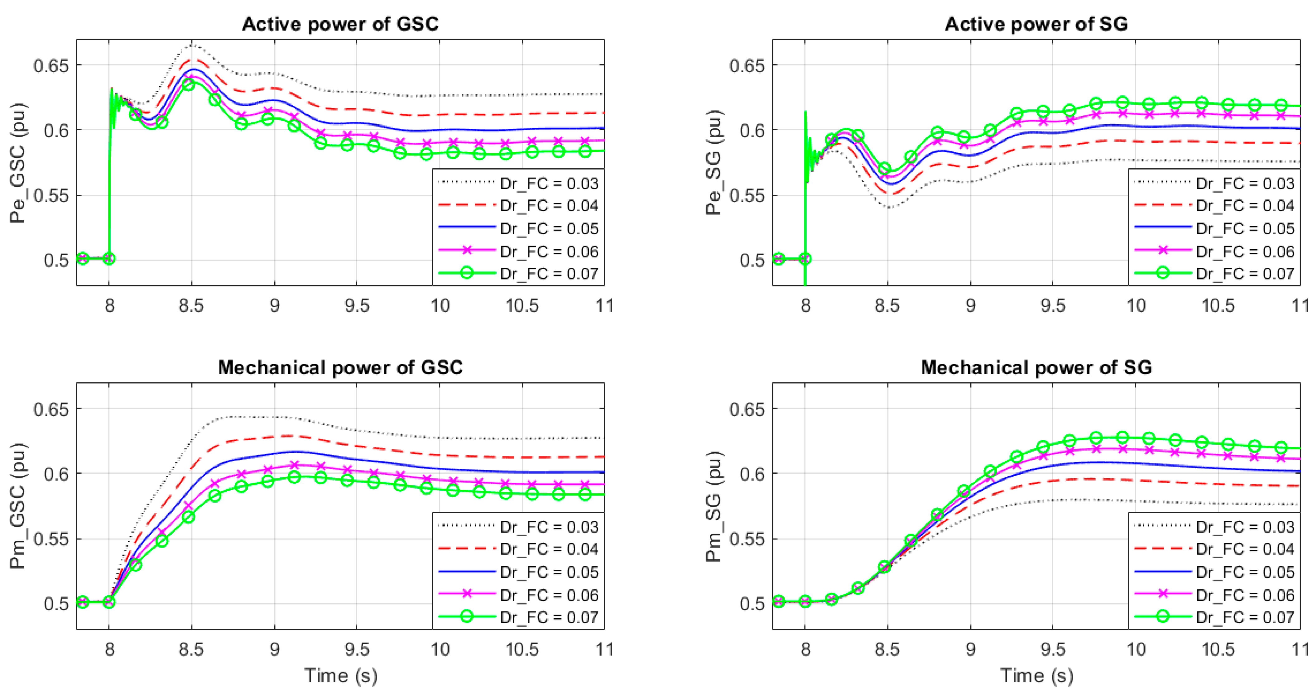
Firstly, we varied the value of inertia constant H in the FC, from 2 to 6 W·s/VA, in unitary steps while the droop coefficient D r was kept constant at 0.05. The results are shown in Figure 3 and Figure 4. Secondly, we changed the value of droop coefficient D r in the FC from 0.03 to 0.07, with a step of 0.01 while the inertia constant H was kept constant at 4 W·s/VA. The results are shown in Figure 5 and Figure 6. In both cases, the parameters of the SG were not changed. In the figures, the mechanical power of GSC was the active power reference for its controls ( T m + Δ T in Figure 1).
From Figure 4 we can see that a larger value of inertia constant made the system more damped. From the responses of active power, we could see the interaction between these two generation units and the complementary nature of their outputs. The larger the difference between their inertia constants, the more evident the interaction and complementariness were. From the responses of mechanical power, we could see the slower reaction of the SG because of, e.g., the speed relay or servomotor in its governor, while converter control had the advantage of a fast response, which is important in fast frequency support.
From Figure 6, we can see that droop coefficient did not have as much influence as the inertia constant on system damping. With different values of the droop coefficient, the responses were similar in shape. The responses of active power and mechanical power also proved the correct load sharing between these two units with different droop coefficients.

3.2. Influence on RoCoF and Frequency Nadir

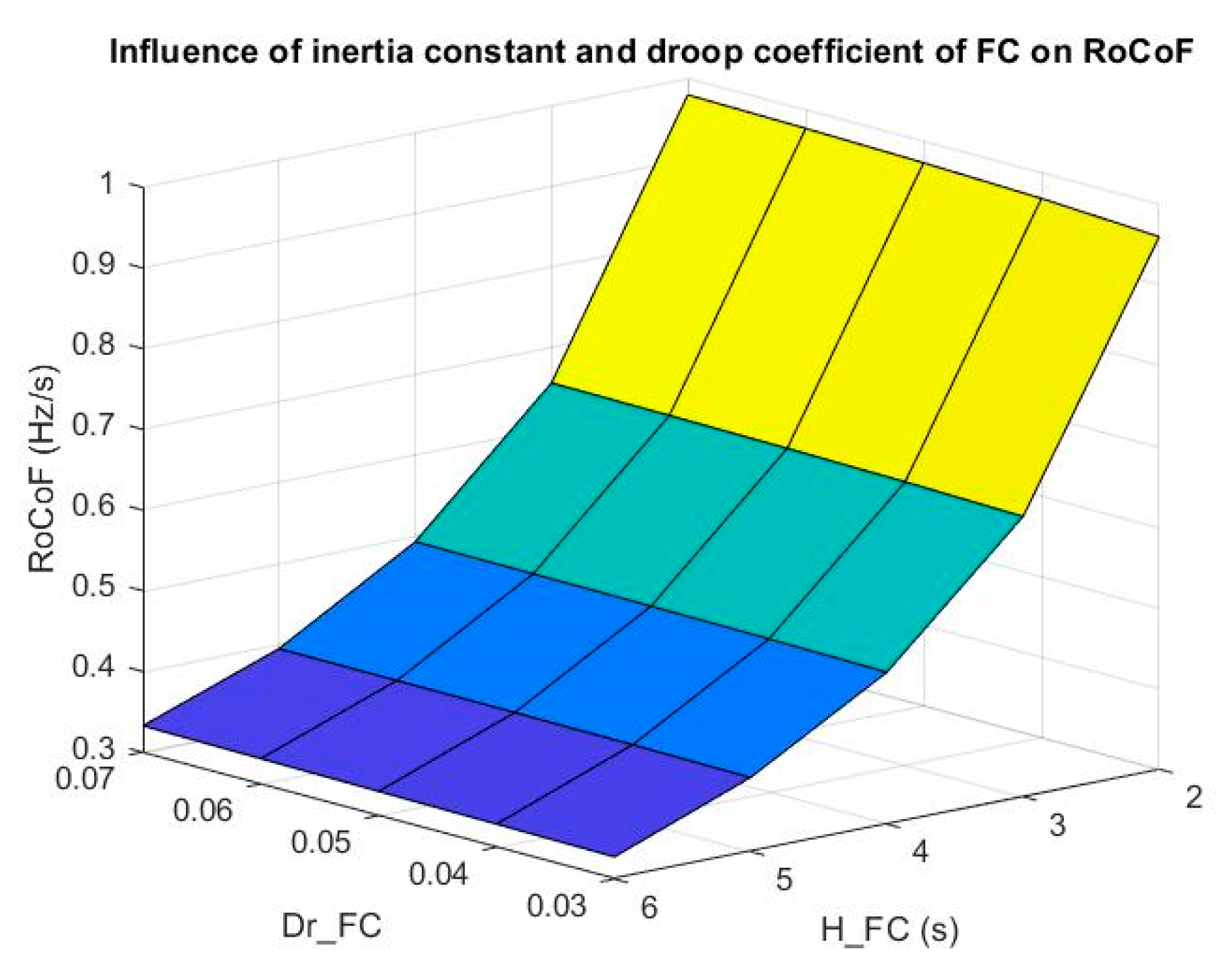
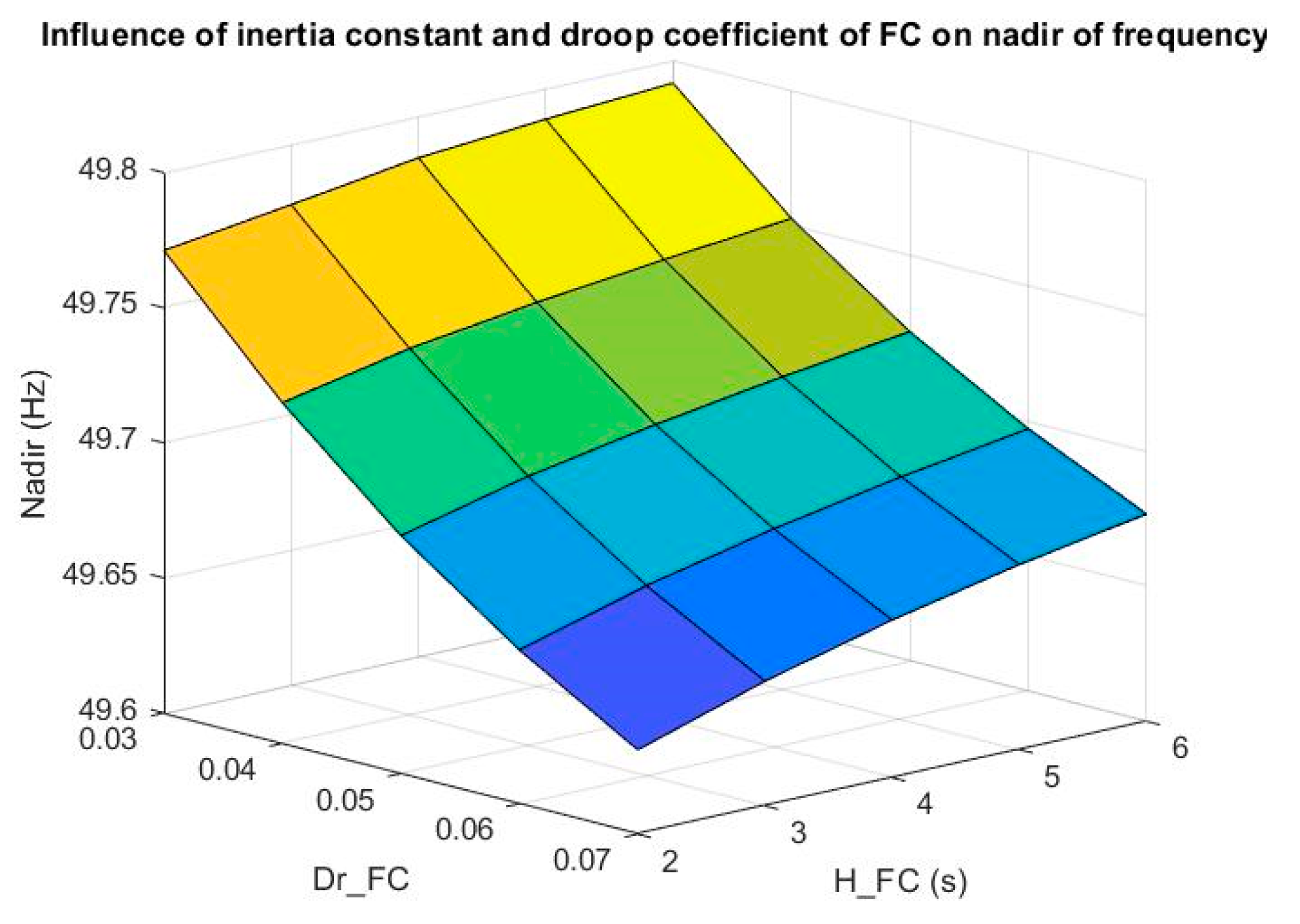
The focus now is on the impact of inertia constant H and droop coefficient D r on the RoCoF and nadir of frequency after an underfrequency event, for each combination of H and D r . The results are shown in Figure 7 and Figure 8.
From the results, we could get the following conclusions:
(1)
An increase of inertia constant decreased RoCoF, which is desirable for frequency support.
(2)
Droop coefficient had little influence on RoCoF, which was slightly reduced with decreasing droop coefficient.
(3)
RoCoF was mainly influenced by inertia constant.
(4)
Inertia constant had little influence on nadir, which was slightly improved when increasing inertia constant. A higher nadir is desirable for frequency support.
(5)
A decrease of droop coefficient increased nadir.
(6)
Nadir of frequency was mainly influenced by droop coefficient.
Therefore, from the perspective of frequency support, it is desirable to have a larger inertia constant and a smaller droop coefficient.
To design appropriate values for inertia constant and droop coefficient in the FC, not only its frequency support capability needs to be evaluated, but also system stability should be considered. Moreover, the exact value of inertia constant also depends, among others, on the grid codes regarding PFC and converter ratings. The recommendation of exact values of inertia constant will be our future work, considering more practical application scenarios and constraints.
Although a smaller droop coefficient is beneficial for frequency support, a lower value also means increased power needed to be extracted from a WT to support the frequency. This is limited by the ratings of the turbine, the generator, the converter, or by the available energy (from wind or storage). In addition, rating translates into higher cost, which is a big concern in industrial applications. Furthermore, this value of the droop coefficient may also be regulated by grid codes. Same as the inertia constant, recommendation of an exact value of droop coefficient will be our future work, after considering more practical application scenarios and constraints.

4. Conclusions

In this paper, we proposed a frequency controller in the GSC control scheme, which aimed to enhance WTs’ frequency support capability. The frequency controller only emulated the swing equation for virtual inertial response and included f-P droop control for the primary frequency control. Compared with other methods in the literature, the proposed frequency controller achieved satisfactory frequency support with considerable simplicity. Cascaded inner loops enable WTs to operate in the grid-forming mode with overcurrent protection. Simulations proved correct operations of the proposed frequency controller and GSC control scheme.
In a system with the FC-controlled GSC connected with a SG, we investigated the influence of parameters in the frequency controller, inertia constant, and droop coefficient, on the system’s dynamic responses and frequency support performance. RoCoF and nadir of frequency were used as metrics in an underfrequency event. From the results, we concluded that a larger inertia constant was beneficial for frequency support, which reduced RoCoF and improved nadir. Similarly, a smaller droop coefficient was advantageous for frequency support, which decreased RoCoF and increased nadir. In addition, RoCoF was mainly influenced by inertia constant, while nadir was mainly affected by the droop coefficient.

Author Contributions

Conceptualization, L.L. and N.A.C.; methodology, L.L., O.S.-R. and N.A.C.; software, L.L. and O.S.-R.; validation, L.L. and O.S.-R.; formal analysis, L.L., O.S.-R. and N.A.C.; investigation, L.L., O.S.-R. and N.A.C.; resources, L.L. and O.S.-R.; data curation, L.L., O.S.-R. and N.A.C.; writing—original draft preparation, L.L.; writing—review and editing, L.L., O.S.-R. and N.A.C.; visualization, L.L., O.S.-R. and N.A.C.; supervision, O.S.-R. and N.A.C.; project administration, L.L.; funding acquisition, N.A.C. All authors have read and agreed to the published version of the manuscript.

Funding

This research was funded by the European Union’s Horizon 2020 research and innovation program under grant agreement No. 727680 (TotalControl) and project PowerKey (EUDP Project No. 12558).

Institutional Review Board Statement

Not applicable.

Informed Consent Statement

Not applicable.

Data Availability Statement

Not applicable.

Conflicts of Interest

The authors declare no conflict of interest.

Appendix A

A salient pole rotor was modeled in the SG, hence there was no parameter q axis transient reactance X q , open-circuit ( T q o ), or short-circuit ( T q ) time constant. The d axis is the short-circuit and q axis is the open-circuit.
Table A1. Per unit representation and simulation settings.
ParameterValueParameterValue
Power base, S b 10 kVAInductance base, L b = Z b / ω b 0.0509 H
Voltage base (phase-to-ground, peak), V b 326.5986 VCapacitance base, C b = 1 / Z b / ω b 1.9894 × 10⁻⁴ F
Current base, I b = S b / V b × 2 / 3 20.4124 ASimulation time step, T s 160 × 10−6 s
Impedance base, Z b = V b / I b 16 ΩInitial power set point of GSC, P r e f _ V S M 0.5 pu
Frequency base, f b 50 HzInitial power set point of SG, P r e f _ S G 0.5 pu
Angular speed base, ω b = 2 π f b 314.1593 rad/s
Table A2. Parameters of the wind turbine (WT) GSC.
ParameterValueParameterValue
Nominal active power, P n 10 kWFilter capacitance, C f 0.05 pu
Nominal voltage (phase-to-phase, RMS), V n 400 VCurrent loop time constant, τ c 7.9577 × 10⁻⁴ s
Nominal current (RMS), I n 14.43 ACurrent loop proportional gain, K p c 0.4
Nominal frequency, f n 50 HzCurrent loop integral gain, K i c 0.1571
DC-link voltage, V D C 800 VVoltage loop proportional gain, K p v 0.0667
Converter switch-on resistance, R o n 1× 10⁻³Voltage loop reciprocal of integration time, z139.6263
Filter resistance, R f 1× 10⁻³Inertia constant, H4 W·s/VA
Filter inductance, L f 0.1 puDroop coefficient, D r 0.05
Table A3. Parameters of the synchronous generator (SG) and line.
ParameterValueParameterValue
Capacity, S n 10 kVAd axis transient short-circuit time constant, T d 1.01 s
Nominal voltage (phase-to-phase, RMS), V n 400 Vd axis subtransient short-circuit time constant, T d 0.053 s
Nominal current (RMS), I n 14.43 Aq axis subtransient open-circuit time constant, T q o 0.1 s
Nominal frequency, f n 50 HzStator resistance, R s 2.8544 × 10⁻³ pu
Number of pole pairs1Friction factor, F0
d axis synchronous reactance, X d 1.305 puInertia constant, H4 W·s/VA
d axis transient reactance, X d 0.296 puDroop coefficient, D r 0.05
d axis subtransient reactance, X d 0.252 puGovernor time constant, T g 0.2 s
q axis synchronous reactance, X q 0.474 puSteam turbine time constant, T c h 0.3 s
q axis subtransient reactance, X q 0.243 puLine resistance, R l 0.01 pu
Leakage reactance, X l 0.18 puLine inductance, L l 0.2 pu

References

  1. Komusanac, I.; Brindley, G.; Fraile, D.; Walsh, C. Wind Energy in Europe in 2019—Trends and Statistics; Wind Europe: Brussels, Belgium, 2020. [Google Scholar]
  2. Gautam, D.; Goel, L.; Ayyanar, R.; Vittal, V.; Harbour, T. Control strategy to mitigate the impact of reduced inertia due to doubly fed induction generators on large power systems. IEEE Trans. Power Syst. 2011, 26, 214–224. [Google Scholar] [CrossRef]
  3. Mullane, A.; O’Malley, M. The inertial response of induction-machine-based wind turbines. IEEE Trans. Power Syst. 2005, 20, 1496–1503. [Google Scholar] [CrossRef]
  4. Holdsworth, L.; Ekanayake, J.B.; Jenkins, N. Power system frequency response from fixed speed and doubly fed induction generator-based wind turbines. Wind Energy 2004, 7, 21–35. [Google Scholar] [CrossRef]
  5. Fang, J.; Li, H.; Tang, Y.; Blaabjerg, F. On the Inertia of Future More-Electronics Power Systems. IEEE J. Emerg. Sel. Top. Power Electron. 2019, 7, 2130–2146. [Google Scholar] [CrossRef]
  6. ENTSO-E. Rate of Change of Frequency (RoCoF) Withstand Capability; European Network of Transmission System Operation for Electricity: Brussels, Belgium, 2018. [Google Scholar]
  7. Uijlings, W. RoCoF An Independent Analysis on the Ability of Generators to Ride through Rate of Change of Frequency Values up to 2 Hz/s; DNV KEMA Energy & Sustainability: London, UK, February 2013. [Google Scholar]
  8. Tamrakar, U.; Shrestha, D.; Maharjan, M.; Bhattarai, B.P.; Hansen, T.M.; Tonkoski, R. Virtual Inertia: Current Trends and Future Directions. Appl. Sci. 2017, 7, 654. [Google Scholar] [CrossRef]
  9. Morren, J.; de Haan, S.W.H.; Kling, W.L.; Ferreira, J.A. Wind Turbines Emulating Inertia and Supporting Primary Frequency Control. IEEE Trans. Power Syst. 2006, 21, 433–434. [Google Scholar] [CrossRef]
  10. Durrant, M.; Werner, H.; Abbott, K. Model of a VSC HVDC terminal attached to a weak AC system. In Proceedings of the IEEE Conference on Control Applications, Istanbul, Turkey, 25 June 2003. [Google Scholar]
  11. Harnefors, L.; Bongiorno, M.; Lundberg, S. Input-admittance calculation and shaping for controlled voltage-source converters. IEEE Trans. Ind. Electron. 2007, 54, 3323–3334. [Google Scholar] [CrossRef]
  12. Wen, B.; Boroyevich, D.; Burgos, R.; Mattavelli, P.; Shen, Z. Small-Signal Stability Analysis of Three-Phase AC Systems in the Presence of Constant Power Loads Based on Measured d-q Frame Impedances. IEEE Trans. Power Electron. 2015, 30, 5952–5963. [Google Scholar] [CrossRef]
  13. Wang, X.; Taul, M.G.; Wu, H.; Liao, Y.; Blaabjerg, F.; Harnefors, L. Grid-Synchronization Stability of Converter-Based Resources—An Overview. IEEE Open J. Ind. Appl. 2020, 1, 115–134. [Google Scholar] [CrossRef]
  14. Beck, H.P.; Hesse, R. Virtual synchronous machine. In Proceedings of the 2007 9th International Conference on Electrical Power Quality and Utilisation, Barcelona, Spain, 9–11 October 2007. [Google Scholar]
  15. Zhong, Q.-C.; Weiss, G. Synchronverters: Inverters That Mimic Synchronous Generators. IEEE Trans. Ind. Electron. 2011, 58, 1259–1267. [Google Scholar] [CrossRef]
  16. Zhang, W.; Cantarellas, A.M.; Rocabert, J.; Luna, A.; Rodriguez, P. Synchronous Power Controller with Flexible Droop Characteristics for Renewable Power Generation Systems. IEEE Trans. Sustain. Energy 2016, 7, 1572–1582. [Google Scholar] [CrossRef]
  17. D’Arco, S.; Suul, J.A.; Fosso, O.B. A Virtual Synchronous Machine implementation for distributed control of power converters in SmartGrids. Electr. Power Syst. Res. 2015, 122, 180–197. [Google Scholar] [CrossRef]
  18. Qu, Z.; Yang, H.; Han, J.; Song, C.; Li, W.; Cai, Y. Effects analysis of excitation circuit on power control for VSG: A design-oriented study. IET Renew. Power Gener. 2020, 14, 803–810. [Google Scholar] [CrossRef]
  19. Kazmierkowski, M.P.; Malesani, L. Current control techniques for three-phase voltage-source pwm converters: A survey. IEEE Trans. Ind. Electron. 1998, 45, 691–703. [Google Scholar] [CrossRef]
  20. D’Arco, S.; Suul, J.A.; Fosso, O.B. Small-signal modelling and parametric sensitivity of a Virtual Synchronous Machine. In Proceedings of the 2014 Power Systems Computation Conference, PSCC 2014, Wroclaw, Poland, 18–22 August 2014. [Google Scholar]
  21. Mo, O.; Hernes, M.; Ljøkelsøy, K. Active damping of oscillations in LC-filter for line connected, current controlled, PWM voltage source converters. In Proceedings of the 10th European Conference on Power Electronics and Applications, Toulouse, France, 2–5 September 2003. [Google Scholar]
  22. Malinowski, M.; Kazmierkowski, M.P.; Bernet, S. New Simple Active Damping of Resonance in Three-Phase PWM Converter with LCL Filter. In Proceedings of the 2005 IEEE International Conference on Industrial Technology, Hong Kong, China, 14–17 December 2005. [Google Scholar]
  23. Kundur, P. Power System Stability And Control; McGraw-Hill, Inc.: New York, NY, USA, 1994; ISBN 0-07-035958-X. [Google Scholar]
  24. Alipoor, J.; Miura, Y.; Ise, T. Distributed Generation Grid Integration Using Virtual Synchronous Generator with Adoptive Virtual Inertia. In Proceedings of the IEEE Energy Conversion Congress and Exposition, Oregon, Portland, 23–27 September 2018. [Google Scholar]
  25. Alipoor, J.; Miura, Y.; Ise, T. Power system stabilization using virtual synchronous generator with alternating moment of inertia. IEEE J. Emerg. Sel. Top. Power Electron. 2015, 3, 451–458. [Google Scholar] [CrossRef]
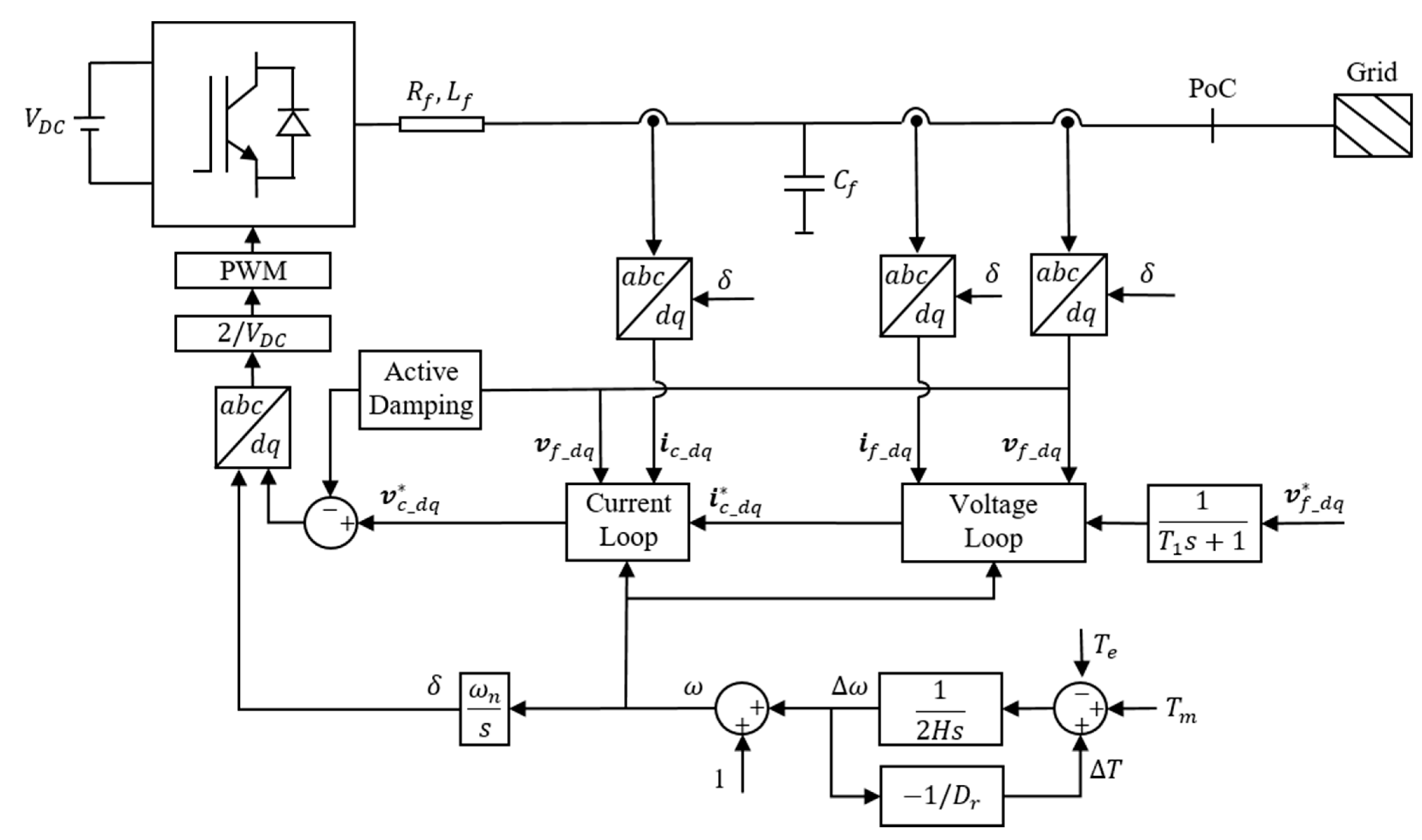
Figure 1. Investigated grid-side converter (GSC) control scheme.
Energies 14 00528 g001
Figure 2. The simulation model.
Energies 14 00528 g002
Figure 3. Influence of the inertia constant H on the virtual rotating speed of FC (H_SG = 4 W·s/VA, D r _ F C = D r _ S G = 0.05 ).
Energies 14 00528 g003
Figure 4. Influence of the inertia constant H on the system’s response (H_SG = 4 W·s/VA, D r _ F C = D r _ S G = 0.05 ).
Energies 14 00528 g004
Figure 5. Influence of the droop coefficient D r on the virtual rotating speed of FC (H_FC = H_SG = 4 W·s/VA, D r _ S G = 0.05 ).
Energies 14 00528 g005
Figure 6. Influence of the droop coefficient D r on the virtual rotating speed of FC (H_FC = H_SG = 4 W·s/VA, D r _ S G = 0.05 ).
Energies 14 00528 g006
Figure 7. Influence of H and D r on RoCoF.
Energies 14 00528 g007
Figure 8. Influence of H and D r on nadir of frequency.
Energies 14 00528 g008
Publisher’s Note: MDPI stays neutral with regard to jurisdictional claims in published maps and institutional affiliations.