Article

An Innovative 500 W Alkaline Water Electrolyser System for the Production of Ultra-Pure Hydrogen and Oxygen Gases

by
Boguslaw Pierozynski
1,*,
Tomasz Mikolajczyk
1,*,
Boguslaw Wojciechowski
2 and
Mateusz Luba
1
1
Department of Chemistry, Faculty of Environmental Management and Agriculture, University of Warmia and Mazury in Olsztyn, Lodzki Square 4, 10-727 Olsztyn, Poland
2
Bob Energetyk Ltd., Jutrzenki 94 Street, 02-230 Warsaw, Poland
*
Authors to whom correspondence should be addressed.
Energies 2021, 14(3), 526; https://doi.org/10.3390/en14030526
Submission received: 24 December 2020 / Revised: 18 January 2021 / Accepted: 18 January 2021 / Published: 20 January 2021
(This article belongs to the Section A5: Hydrogen Energy)

Abstract

:
This paper communicates on an innovative, laboratory size alkaline water electrolyser (AWE) system, capable of efficiently producing ultra-pure hydrogen and oxygen gases. The system is composed of a zero-gap, bipolar-electrode stack, equipped with a polymer-based membrane, along with two drying columns for effective purification of H2 and O2 gaseous products. An optimal electrochemical efficiency of the electrolyser stack is provided through the employment of catalytically activated, extended surface-area nickel foam electrodes. Laboratory electrochemical examinations of the electrolyser included a series of galvanostatic AWE and alternating current (a.c.) impedance (single cell) experiments. Complementary examinations covered catalyst’s surface topography analysis by combined SEM (Scanning Electron Microscopy) and EDX (Energy Dispersive X-ray Spectroscopy) techniques along with chromatographic evaluation of the purity of hydrogen and oxygen products.

1. Introduction

As environmental regulations become more and more demanding, compressed hydrogen gas attracts great attention as a future energy carrier. In fact, when combined with renewable electricity sources (e.g., solar or wind), H2 produced by alkaline or PEM (Proton-Exchange Membrane) water electrolysis process could be considered as the only 100% environmentally friendly, ultra-high-purity fuel. It could then be utilised to generate electrical energy in PEM fuel cell devices or to produce heat in hydrogen furnaces. So far, due to the high cost of electrolytic hydrogen, as well as that of PEM fuel cell stacks, implementation of this energy solution is usually restricted to special applications, where cost is not of superior importance. The above includes the police and fire department, various rescue teams and special military usage. However, due to their continuous and dynamic progress, hydrogen-powered automotive and small- to mid-scale energy generator systems are anticipated to play a crucial role beyond the year 2020 [1,2,3,4,5,6,7,8,9,10].
This communication reports on basic electrochemical testing of a laboratory-scale, 500 W alkaline water electrolyser system, capable of generating high-quality hydrogen and oxygen products. Most importantly, the electrode system employs unmodified and Pd-activated Ni foam cathodes, and electro-oxidised nickel foam anodes, as previously produced from this laboratory [11,12,13,14].

2. Materials and Methods

All electrochemical experiments were carried-out in 8 M KOH (p.a. POCH, Poland) solution at 45 °C, made up using a Direct-Q3® Ultraviolet (UV) ultra-pure water purification system from Millipore, with 18.2 MΩ cm water resistivity. Single-cell tests (galvanostatic and a.c. impedance measurements) were conducted by means of the Solartron 12,608 W Full Electrochemical System, consisting of 1260 Frequency Response Analyser (FRA) and 1287 Electrochemical Interface (EI) (see Figure 1 below). On the other hand, a 30 V/30 A direct current (dc.) power supply unit (PeakTech®, Ahrensburg, Germany) was used to perform all galvanostatic alkaline water electrolyser (AWE) experiments on the electrolyser stack (see the 500 W AWE system in Figure 2). In addition, determination of the purity of hydrogen and oxygen gas samples was carried out with the use of a gas chromatograph (GC)—Shimadzu GC2014 model, equipped with a chromatographic column and a helium detector with pulse discharge (PD-HID—Pulsed Discharge Helium Ionisation Detector). The analysis conditions were as follows: ShinCarbon ST 80–100 column, length 2 m, diameter 2 mm, Ar carrier gas, sample’s volume: 500 µL. The GC analysis was performed at an argon gas flow of 15 mL min−1. The temperature of the injector and detector was set at 200 °C. The chromatographic separation was performed by the following program: initial temperature was set at 40 °C and held for 4 min, then it was raised to 200 °C at a rate of 15 °C min−1. The final temperature was maintained for 2 min.
The alkaline water electrolyser (AWE) system with a nominal power of approximately 500 W was designed by the University of Warmia and Mazury (UWM) research team and constructed by an external company. The electrolyser stack with a bipolar, zero-gap electrode arrangement (made of polypropylene (PP)) consisted of nine electrochemical cells connected in series. Each cell had a separate electrolyte supply and an outflow of recirculated solution, as well as those of hydrogen and oxygen gases released during the electrolysis. The cells were divided into two parts (anodic and cathodic), separated by a Zirfon Perl UTP 500 membrane (12 × 12 cm × 500 µm) made of polyphenylene sulphide and zirconium oxide (AGFA). Prior to being installed in the electrolyser, Zirfon membranes were rinsed in ultra-pure water and soaked in 2 M KOH solution for 24 h.
Due to the cell’s structure, the distance between the anode and cathode was just 0.5 mm, being practically equal to the membrane thickness. The electrical contact between individual cells of the stack was optimised (through minimising the resistance parameter) by installing 316 L stainless-steel-made wire mesh and adjustable screws within the cells. The tightness of the connections between the individual elements was ensured by means of Teflon tape and the whole stack was put together with 316 L stainless-steel-made bolts and nuts to a pre-set torque (see Figure 3a–e). Nickel foam (>99.99% Ni, MTI Corporation, Richmond, CA, USA) or Pd-activated Ni foam (10 × 10 × 0.16 cm) with palladium nanoparticles (ca. 10 nm in diameter) in the average amount of 0.05–0.10 wt.% was employed as cathodes, whereas in-situ electro-oxidised nickel foam was used as an anode material (see Figure 4a–c and Table 1 and Table 2 for detail). It should be stressed that electrochemically active surface area of Ni foam (with 1 × 1 cm2 of geometrical area and mass of 33.4 mg) was previously estimated by a.c. impedance spectroscopy at 13.9 cm2 [11]. On the other hand, electrochemical oxidation of nickel foam led to significant changes in surface topography (compare Figure 4b,c), also evidenced through a radical increase of oxygen content for the electro-oxidised Ni foam samples (Table 2). Also, all procedures employed for the preparation of Ni foam electrodes were the same as those described in References [11,12,13,14].

3. Results and Discussion

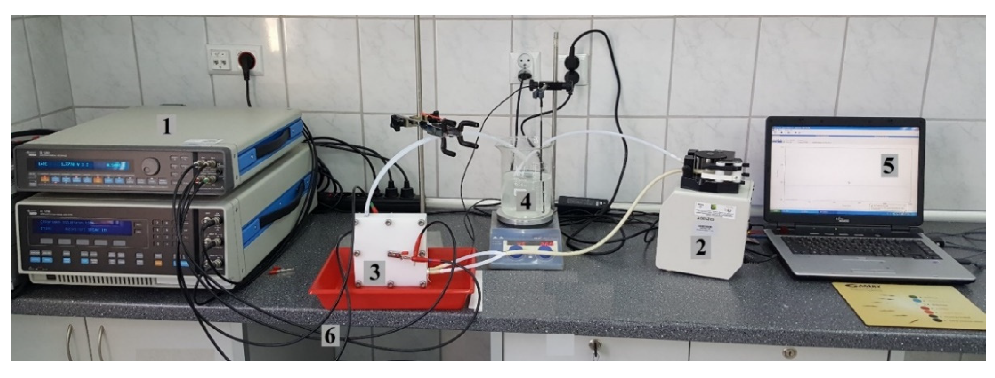
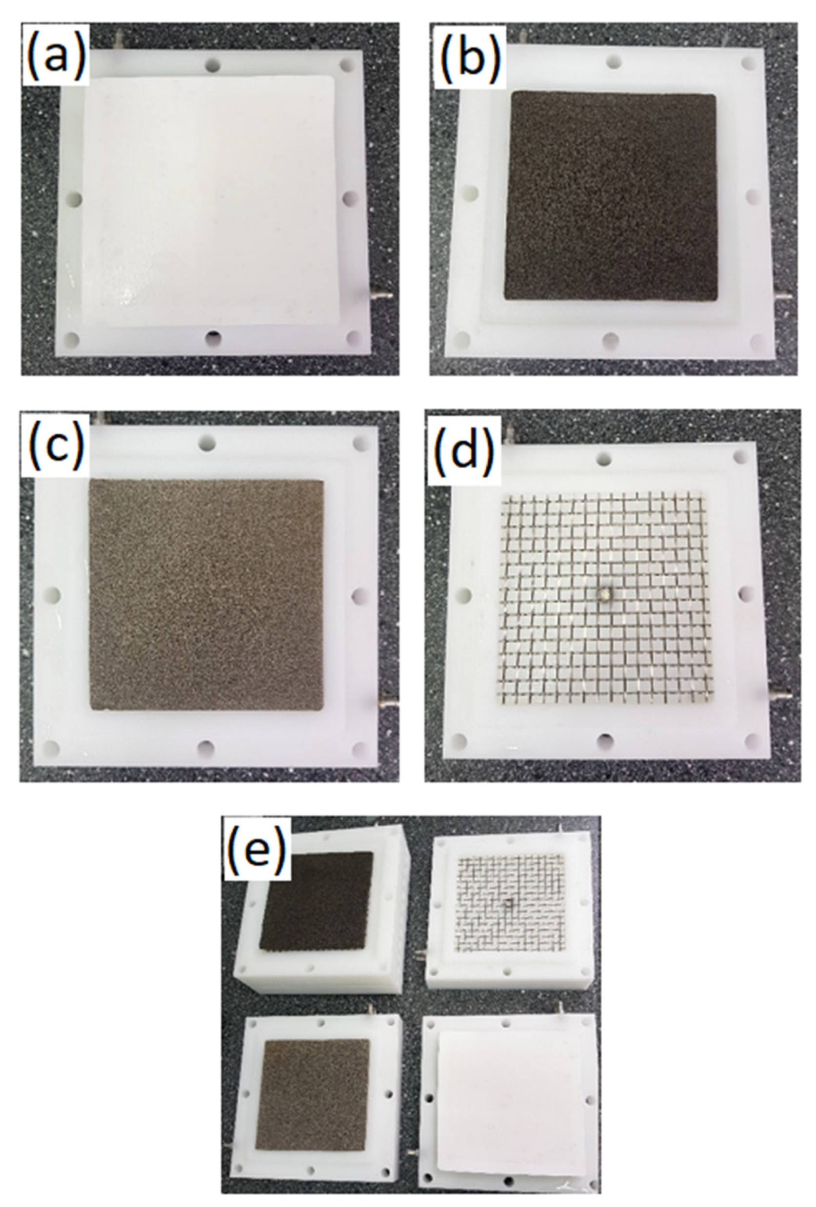
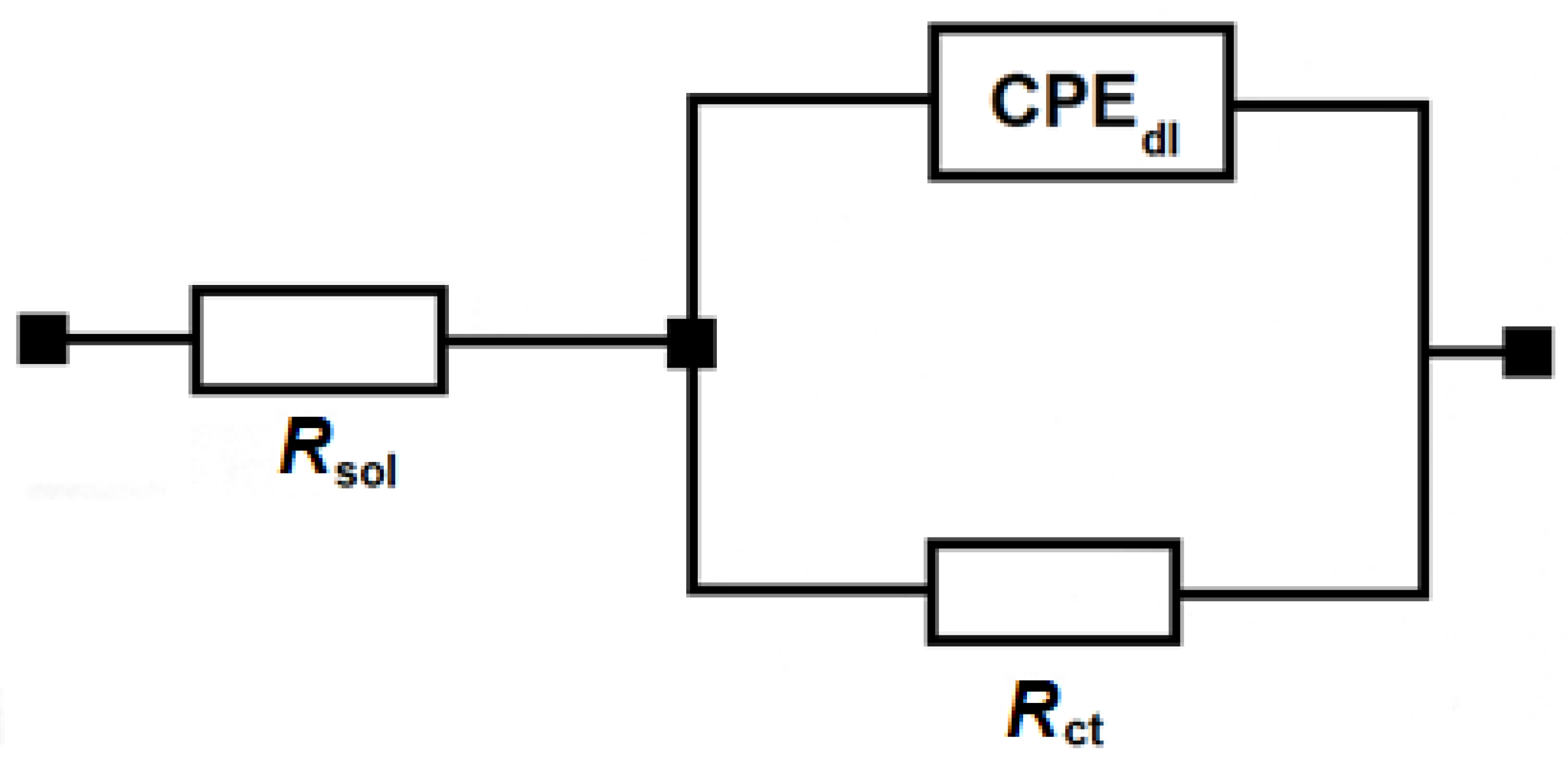
3.1. Single-Cell Electrochemical AWE Tests

Initial electrochemical experiments were carried-out on a single cell of the electrolyser stack (see Figure 1), operated in a continuous electrolyte recirculation mode (at 20 cm3 min−1). Figure 5 illustrates the dependence of voltage in function of the electrolysis time, carried out in a galvanostatic mode. Thus, the obtained mean values of the cell’s voltage (for the current intensity of 0.5 A) were respectively 1.780 ± 0.005 V and 1.647 ± 0.003 V for the cathodes made of unmodified and Pd-activated nickel foam electrodes, respectively. Raising the current intensity to 1.0 A led to elevation of the single-cell electrolyser’s average voltage to 1.867 ± 0.001 and 1.794 ± 0.009 V, correspondingly. In addition, surface electro-oxidation of Ni foam anode did not cause any significant impact on the cell’s voltage (see Figure 5).
Electrochemical impedance measurements were also performed on the above-discussed single-cell electrolyser unit, for the five selected cell voltages: 1.50, 1.60, 1.65, 1.70 and 1.80 V over the FRA’s frequency range of 100 kHz to 1 Hz. The recorded Nyquist impedance plots (Figure 6a,b) exhibited somewhat distorted semi-circles, which electrochemically translates into a charge-transfer reaction (Rct resistance in parallel with electrical double-layer capacitance Cd1 parameter). In addition, Table 3 presents the Rct and Cdl parameter results, obtained through fitting the impedance data to a typical constant phase element (CPE)-modified Randles equivalent model (see Figure 7 and Reference [11] for details).
As expected, the increase of the electrolyser’s voltage from 1.50 to 1.80 V resulted in radically reduced total value of the recorded charge-transfer resistance within the cell. Hence, the corresponding Rct parameter diminished from 0.94 to 0.09 Ω and from 0.12 to reach 0.06 Ω, for the cathode made of unmodified and the Pd-activated Ni foam, correspondingly. At the same time, the use of Pd nanoparticle catalyst modification resulted in the total Rct reduction by approximately 30% (from 0.09 to 0.06 Ω) for the maximum value of the cell’s voltage (U = 1.80 V). The above corresponds to a ca. 4-fold increase (from 96 to 399 mF) of the measured electrical double-layer capacitance, Cdl parameter (Table 3). This result could primarily be interpreted as a significant increase in the catalytically active surface of nickel foam cathode, due to the deposition of palladium nanoparticles. Thus, facilitation of the water electrolysis process on Pd-activated Ni foam cathode is a combined effect of: (a) an increase in the electrochemically active electrode surface (measurement of the capacitance parameter) and (b) the catalytic properties of Pd nanoparticles in the process of hydrogen evolution.

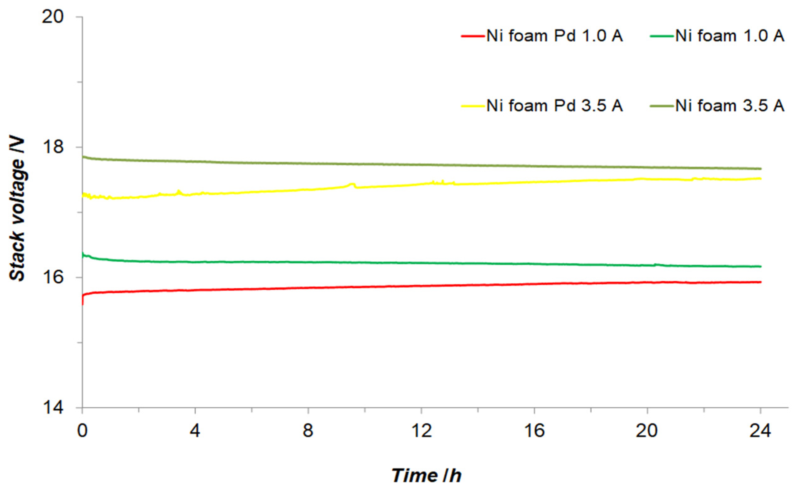
3.2. Electrochemical Examination of Laboratory Size 500 W AWE System

The laboratory electrolyser stack with a nominal power of approximately 500 W was tested under a laboratory fume-hood by means of the measuring system shown in Figure 2, where two silica gel-filled columns were employed for drying hydrogen and oxygen products.
Hence, for the galvanostatic AWE experiments carried out at the current intensity of 1.0 A and the duration of 24 h, the recorded average, steady voltages of the electrolyser stack came respectively to 16.22 ± 0.02 and 15.86 ± 0.04 V for unmodified and the Pd-activated Ni foam cathodes. In the latter case, there was a tendency of voltage increase from 15.60 to 15.93 V (over the period of 24 h), which could be caused by slow deactivation of Pd catalytic sites. Then, the increase of the current intensity to 3.5 A caused elevation of the average voltage of the electrolyser to 17.73 ± 0.03 and 17.40 ± 0.08 V, respectively. In this case, a small voltage rise (from 17.26 to 17.52 V) was also observed for the Pd-modified nickel foam cathodes (see Figure 8). Furthermore, for the current set at 16.0 A, average recorded voltages of the electrolyser came to 22.21 ± 0.03 V (for unmodified cathodes) and 22.03 ± 0.04 V for the Pd-modified Ni foam electrodes (Figure 9).
Finally, in order to confirm the stability and the assumed device’s power of approximately 500 W, extended (7-day-long) water electrolysis tests were also carried out for both cathode arrangements. Initially, the current was set at 23.6 A (Pd-activated Ni foam) and 21.0 A for the unmodified nickel foam electrode systems. Hence, after approximately 130 h of continuous electrolyser operation, the voltages for both tested cathode systems (ca. 23.83 V: Ni foam/Pd and 23.86 V: Ni foam or 2.65 V/cell) became practically equilibrated. At this point, the tested AWE unit stacks reached the power of 501 and 562 W for the unmodified and the Pd-activated Ni foam electrodes, correspondingly. Simultaneously, the obtained results indicated minor, but visible, deactivation effect for the palladium-modified cathodes. The latter effect most likely results from deposition/electrosorption of electrolyte trace pollutants on the Pd-modified cathode surface (for the unmodified cathode system, the voltage changes are even less significant, Figure 10).
The results of chromatographic impurity analysis for the 500 W AWE stack-generated H2 and O2 gas samples are shown in Table 4. Thus, an average purity of four oxygen samples came to 99.59%, whereas that of hydrogen (also calculated as an average of four samples) approached 99.88%.

4. Conclusions

Nickel in the system of extended, 3D electrochemically active surface makes a superior electrode base for the construction of a bipolar, zero-gap alkaline water electrolyser. A catalytic nanoparticle Pd additive (gravimetrically assessed at 0.05–0.10 wt.%) is highly beneficial for the operation of the electrolyser stack, as it enhanced the AWE stack’s efficiency by 12% (from 501 to 562 W). However, preventing a gradual deactivation of the Pd catalyst would require introduction of periodic, short breaks in the device’s operation in conjunction with in-situ electrochemical electrode activation procedures. Also, as nickel foam offers extended electrochemically active surface area material, the a.c. impedance-derived operational current densities [11,15] came to ca. 9 and 193 mA cm−2, at the corresponding current intensities of 1 and 21 A, and geometrical surface area of Ni foam: 10 × 10 cm. In fact, the latter value of current density is close to a typical range of current densities for operational alkaline water electrolysers (200–400 mA cm−2) [16,17]. There are numerous, interesting, laboratory-scale material innovations into water-splitting technology (see, e.g., References [18,19,20]). However, this work is not only in line with current AWE commercial technologies, but its effects could also be transferred to this industry in a timely fashion.
Finally, the use of a high-quality commercial membrane (Zirfon Perl UTP 500) just with single-stage gas drying columns enabled to obtain superb purity of hydrogen and oxygen products, in the order of 99.90% and 99.60%, respectively.

Author Contributions

Conceptualisation, B.P. and B.W.; methodology, B.P. and T.M.; investigation, T.M. and M.L.; data curation, T.M. and M.L.; writing—original draft preparation, B.P.; editing, B.P. and T.M.; supervision, B.P. All authors have read and agreed to the published version of the manuscript.

Funding

Project financially supported by Minister of Science and Higher Education in the range of the program entitled “Regional Initiative of Excellence” for the years 2019–2022, Project No. 010/RID/2018/19, amount of funding 12,000,000 PLN.

Institutional Review Board Statement

Not applicable.

Informed Consent Statement

Not applicable.

Acknowledgments

This work has been financed by the internal research grant no. 20.610.001-300, provided by The University of Warmia and Mazury in Olsztyn. Mateusz Luba would also like to acknowledge a scholarship from the program Interdisciplinary Doctoral Studies in Bioeconomy (POWR.03.02.00-00-1034/16-00), funded by the European Social Fund.

Conflicts of Interest

The authors declare no conflict of interest.

References

  1. Ogawa, T.; Takeuchi, M.; Kajikawa, Y. Analysis of Trends and Emerging Technologies in Water Electrolysis Research Based on a Computational Method: A Comparison with Fuel Cell Research. Sustainability 2018, 10, 478. [Google Scholar] [CrossRef] [Green Version]
  2. Koj, J.C.; Wulf, C.; Schreiber, A.; Zapp, P. Site-Dependent Environmental Impacts of Industrial Hydrogen Production by Alkaline Water Electrolysis. Energies 2017, 10, 860. [Google Scholar]
  3. Brauns, J.; Turek, T. Alkaline Water Electrolysis Powered by Renewable Energy: A Review. Processes 2020, 8, 248. [Google Scholar] [CrossRef] [Green Version]
  4. Babic, U.; Suermann, M.; Büchi, F.N.; Gubler, L.; Schmidt, T.J. Critical Review—Identifying Critical Gaps for Polymer Electrolyte Water Electrolysis Development. J. Electrochem. Soc. 2017, 164, 387–399. [Google Scholar] [CrossRef] [Green Version]
  5. Zeng, K.; Zhang, D. Recent progress in alkaline water electrolysis for hydrogen production and applications. Prog. Energy Combust. Sci. 2010, 36, 307–326. [Google Scholar] [CrossRef]
  6. Christopher, K.; Dimitrios, R. A review on exergy comparison of hydrogen production methods from renewable energy sources. Energy Environ. Sci. 2012, 5, 6640–6651. [Google Scholar] [CrossRef]
  7. Vengatesan, S.; Santhi, S.; Jeevanantham, S.; Sozhan, G. Quaternized poly (styrene-co-vinyl benzyl chloride) anion exchange membranes for alkaline water electrolysers. J. Power Sources 2015, 284, 361–368. [Google Scholar] [CrossRef]
  8. Solmaz, R. Electrochemical preparation and characterization of C/Ni–NiIr composite electrodes as novel cathode materials for alkaline water electrolysis. Int. J. Hydrogen Energy 2013, 38, 2251–2256. [Google Scholar] [CrossRef]
  9. Manabe, A.; Kashiwase, M.; Hashimoto, T.; Hayashida, T.; Kato, A.; Hirao, K.; Shimomura, I.; Nagashima, I. Basic study of alkaline water electrolysis. Electrochim. Acta 2013, 100, 249–256. [Google Scholar] [CrossRef]
  10. Rashid, M.M.; Al Mesfer, M.K.; Naseem, H.; Danish, M. Hydrogen Production by Water Electrolysis: A Review of Alkaline Water Electrolysis, PEM Water Electrolysis and High Temperature Water Electrolysis. Int. J. Eng. Adv. Technol. 2015, 4, 80–93. [Google Scholar]
  11. Pierozynski, B.; Mikolajczyk, T.; Kowalski, I.M. Hydrogen evolution at catalytically-modified nickel foam in alkaline solution. J. Power Sources 2014, 271, 231–238. [Google Scholar] [CrossRef]
  12. Pierozynski, B.; Mikolajczyk, T. On the Temperature Dependence of Hydrogen Evolution Reaction at Nickel Foam and Pd-Modified Nickel Foam Catalysts. Electrocatalysis 2015, 6, 51–59. [Google Scholar] [CrossRef] [Green Version]
  13. Pierozynski, B.; Mikolajczyk, T. Cathodic Evolution of Hydrogen on Platinum-Modified Nickel Foam Catalyst. Electrocatalysis 2016, 7, 121–126. [Google Scholar] [CrossRef] [Green Version]
  14. Pierozynski, B.; Mikolajczyk, T.; Luba, M.; Zolfaghari, A. Kinetics of oxygen evolution reaction on nickel foam and platinum-modified nickel foam materials in alkaline solution. J. Electroanal. Chem. 2019, 847, 113194–113201. [Google Scholar] [CrossRef]
  15. Martin, M.H.; Lasia, A. Influence of Experimental Factors on the Constant Phase Element Behavior of Pt Electrodes. Electrochim. Acta 2011, 56, 8058–8068. [Google Scholar] [CrossRef]
  16. Marini, S.; Salvi, P.; Nelli, P.; Pesenti, R.; Villa, M.; Berrettoni, M.; Zangari, G.; Kiros, Y. Advanced Alkaline Water Electrolysis. Electrochim. Acta 2012, 82, 384–391. [Google Scholar] [CrossRef]
  17. Mergel, J.; Carmo, M.; Fritz, D. Status on Technologies for Hydrogen Production by Water Electrolysis. In Transition to Renewable Energy Systems; Stolten, D., Scherer, V., Eds.; Wiley-VCH Verlag GmbH & Co. KGaA: Weinheim, Germany, 2013; pp. 423–450. ISBN 978-3-527-67387-2. [Google Scholar]
  18. Elayappan, V.; Shanmugam, R.; Chinnusamy, S.; Yoo, D.J.; Mayakrishnan, G.; Kim, K.; Noh, H.S.; Kim, M.K.; Lee, H. Three-Dimensional Bimetal TMO Supported Carbon Based Electrocatalyst Developed via Dry Synthesis for Hydrogen and Oxygen Evolution. Appl. Surf. Sci. 2020, 505, 144642. [Google Scholar] [CrossRef]
  19. Ramakrishnan, S.; Balamurugan, J.; Vinothkannan, M.; Kim, A.R.; Sengodan, S.; Yoo, D.J. Nitrogen-Doped Graphene Encapsulated FeCoMoS Nanoparticles as Advanced Trifunctional Catalyst for Water Splitting Devices and Zinc–Air Batteries. Appl. Catal. B Environ. 2020, 279, 119381. [Google Scholar] [CrossRef]
  20. Shi, Y.; Gao, W.; Lu, H.; Huang, Y.; Zuo, L.; Fan, W.; Liu, T. Carbon-Nanotube-Incorporated Graphene Scroll-Sheet Conjoined Aerogels for Efficient Hydrogen Evolution Reaction. ACS Sustain. Chem. Eng. 2017, 5, 6994–7002. [Google Scholar] [CrossRef]
Figure 1. Single-cell measuring system of a laboratory polypropylene (PP)-made alkaline water electrolyser (cell’s dimensions: 15 × 15 × 3.5 cm, including electrodes: 10 × 10 × 0.16 cm), where: 1 is Solartron 12,608 W electrochemical measuring system, 2 is Gilson Minipuls 3 peristaltic recirculation pump, 3 is electrolyser cell, 4 is laboratory electrolyte heater, 5 is control laptop computer and 6 are electrical connections.
Energies 14 00526 g001
Figure 2. Measurement system of a laboratory 500 W alkaline water electrolyser unit (PP stack dimensions: 15 × 15 × 25.5 cm, with nine cells connected in series), where: 1 is a dc. 30 V/30 A power supply from PeakTech, 2 is Gilson Minipuls 3 peristaltic electrolyte recirculation pump, 3 is electrolyser stack, 4 is electrolyte heater with electronic controller, 5 is silica gel beads-based hydrogen desiccant column, 6 is silica gel beads-based oxygen desiccant column, 7 is periodically replenished electrolyte recirculation tank, 8 is anolyte reservoir, 9 is catholyte reservoir, 10 is dry hydrogen outlet and 11 is dry oxygen outlet.
Energies 14 00526 g002
Figure 3. Structural elements of water electrolyser system: (a) membrane fitting in a single cell, (b,c) location of Pd-activated and unmodified Ni foam cathodes inside the cell respectively, (d) location of stainless-steel-made wire mesh and the cell’s connecting screws, (e) combining individual cells into an electrolyser stack (stainless-steel-made solution recirculation/gas discharge ports are clearly visible).
Energies 14 00526 g003
Figure 4. (a) SEM micrograph picture (recorded at 1000× magnification) and EDX spectrogram for Pd-activated Ni foam (sample 1, ca. 0.19 wt.% Pd). (b,c) SEM micrograph pictures (recorded at 10,000× magnification) and EDX spectrograms for unmodified and electro-oxidised Ni foam samples, correspondingly (Quanta FEG 250 SEM with Bruker XFlash 5010 EDX supplement were employed).
Energies 14 00526 g004
Figure 5. Single cell’s voltage as a function of electrolysis time. The process was carried out at 45 °C in 8 M KOH solution for current intensities of 0.5 and 1.0 A (anode: Ni foam/electro-oxidised Ni foam; cathode: Ni foam or Pd-modified Ni foam), and solution recirculation rate of 30 cm3 min−1.
Energies 14 00526 g005
Figure 6. Nyquist impedance plots for alkaline water electrolysis process (total impedance measured for a single-cell electrolyser unit), carried out for indicated cell voltages, on cathodes of unmodified (a) and palladium-activated nickel foam material (b), recorded in 8 M KOH at 45 °C.
Energies 14 00526 g006
Figure 7. An equivalent circuit, used for fitting the obtained a.c. impedance spectroscopy data in this work, where: Rsol is solution resistance, Cdl is double-layer capacitance and Rct is a total charge-transfer resistance parameter. The circuit includes a constant phase element (CPE) to account for distributed capacitance.
Energies 14 00526 g007
Figure 8. Electrolyser stack’s voltage in function of electrolysis time. The process was carried out at 45 °C in 8 M KOH solution for current intensities of 1.0 and 3.5 A (anode: Ni foam; cathode: Ni foam or Pd-modified Ni foam), and solution recirculation rate of 50 cm3 min−1.
Energies 14 00526 g008
Figure 9. Electrolyser stack’s voltage in function of electrolysis time. The process was carried-out at 45 °C in 8 M KOH solution for current intensity of 16.0 A (anode: Ni foam; cathode: Ni foam or Pd-modified Ni foam) and solution recirculation rate of 50 cm3 min−1.
Energies 14 00526 g009
Figure 10. Electrolyser stack’s voltage in function of electrolysis time during long-term (7 days) AWE tests. The process was carried out at 45 °C in 8 M KOH solution for the set current intensities of 21.0 and 23.6 A respectively, for cathodes made of unmodified and Pd-modified nickel foam (solution recirculation rate was set at 50 cm3 min−1).
Energies 14 00526 g010
Table 1. An average, elemental content (wt.%), derived for palladium-modified Ni foam cathodes (samples 1 and 2) by means of EDX analysis.
ElementSampleContent
Ni194.53
293.05
C13.16
24.35
O12.12
22.35
Pd10.19
20.25
Table 2. Elemental content (wt.%), derived for three unmodified nickel foam electrodes and electro-oxidised Ni foam anodes by means of EDX analysis.
SampleElementContent
Ni foam 1C2.18
O1.28
Ni96.54
Ni foam 2C1.88
O1.20
Ni96.92
Ni foam 3C2.24
O1.24
Ni96.52
Ni foam oxidized 1C2.24
O5.94
Ni91.83
Ni foam oxidized 2C2.21
O4.25
Ni93.55
Ni foam oxidized 3C1.82
O3.82
Ni94.36
Table 3. a.c. impedance parameters (total, average values of charge-transfer resistance, Rct and double-layer capacitance, Cdl parameters), derived for a single electrolyser cell (anode: Ni foam; cathode: unmodified and Pd-modified Ni foam) recorded in 8 M KOH solution, at the temperature of 45 °C.
U/VRctCdl/mF
Cathode: Ni foam
1.500.94 140
1.600.58121
1.650.38113
1.700.18103
1.800.0996
Cathode: Pd-modified Ni foam
1.500.12669
1.600.12654
1.650.11486
1.700.08450
1.800.06399
Table 4. Chromatographic analysis of hydrogen and oxygen gas samples generated by means of 500 W AWE stack.
SampleConstituentsContent/%
Oxygen 1O299.83
H2O0.17
Oxygen 2O298.71
H21.11
H2O0.18
Oxygen 3O299.96
H2O0.04
Oxygen 4O299.87
H2O0.13
Hydrogen 1H299.86
H2O0.14
Hydrogen 2H299.85
H2O0.15
Hydrogen 3H299.94
H2O0.06
Hydrogen 4H299.89
H2O0.11
Publisher’s Note: MDPI stays neutral with regard to jurisdictional claims in published maps and institutional affiliations.

