Article

Numerical Study on the Flow and Heat Transfer Characteristics of a Second Throat Exhaust Diffuser According to Variations in Operating Pressure and Geometric Shape

1
Department of Mechanical Engineering, Chungnam National University, Daejeon 34134, Korea
2
The 1st Research and Development Institute, Agency for Defense Development, Daejeon 34186, Korea
*
Author to whom correspondence should be addressed.
Energies 2021, 14(3), 532; https://doi.org/10.3390/en14030532
Submission received: 10 December 2020 / Revised: 8 January 2021 / Accepted: 14 January 2021 / Published: 20 January 2021
(This article belongs to the Special Issue Propulsion and Combustion in Aerospace Systems)

Abstract

:
A numerical study was conducted to investigate the flow and heat transfer characteristics of a supersonic second throat exhaust diffuser for high-altitude simulations. The numerical results were satisfactorily validated by the experimental results. A subscale diffuser using nitrogen was utilized to investigate starting pressure and pressure variation in the diffuser wall. Based on the validated numerical method, the flow and heat transfer characteristics of the diffuser using burnt gas were evaluated by changing operating pressure and geometric shape. During normal diffuser operation without cooling, high-temperature regions of over 3000 K appeared, particularly near the wall and in the diffuser diverging section. After cooling, the flow and pressure distribution characteristics did not differ significantly from those of the adiabatic condition, but the temperature in the subsonic flow section decreased by more than 1000 K. Furthermore, the tendency of the heat flux from the diffuser internal flow to the wall was similar to that of the pressure variations, and it increased with operating pressure. It was confirmed that the heat fluxes of the supersonic and subsonic flows in the diffuser were proportional to the operating pressure to the 0.8 and −1.7 power, respectively. In addition, in the second throat region after separation, the heat flux could be scaled to the Mach number ratio before and after the largest oblique shock wave because the largest shock train affected the heat flux of the diffuser wall.

1. Introduction

Rocket engines used in launch vehicles operate in various environments, ranging from the earth’s atmosphere to outer space. To achieve the stable operation of launch vehicles, engine thrust and stability must be verified within each environment. The expansion ratio of an engine operating at high altitudes is optimized for low-pressure environments. When the engine is tested at ground level, it is difficult to accurately measure the thrust owing to the high ambient pressure (compared with that in high-altitude conditions), which can cause flow separations that result in nozzle vibrations and severe damage. Therefore, a low-pressure environment at the target altitude is required for accurate thrust measurements and stable testing. Goethert reviewed unusual and unexpected problems that occurred in the actual operation of missiles and spacecraft operating in high altitude and space environments, especially in tests of propulsion systems [1].
To simulate actual altitude conditions on the ground, an additional system is required. Generally, a supersonic diffuser and an additional ejector are used to simulate a low-pressure environment around a test nozzle. This supersonic diffuser, with a chamber surrounding the test nozzle, uses a high-velocity flow entrainment around the nozzle exit to simulate a low-pressure environment within the chamber. It is the most widely used device because it is easy to install and does not require any additional equipment. Lijo et al. analyzed the transient flow through a vacuum ejector system, which generates a low-pressure environment for the diffuser start using a computational fluid dynamics method [2]. Sung et al. employed theoretical models and compared numerical simulations with experimental data to investigate the effects of major design parameters such as the area ratio of the diffuser to the rocket–motor nozzle throat zone, vacuum chamber size, rocket–motor pressure, and others to characterize startup and operational conditions [3].
Among the types of supersonic diffusers, the second throat exhaust diffuser (STED) is generally known to be more suitable for testing engines with higher operating pressures than the constant area exhaust diffuser (CAED) because the STED can be operated at a wider range of pressures than the CAED can. Park et al. investigated the effects of the essential geometric factors of the STED (such as second throat area ratio, nozzle expansion ratio, and nozzle contour) on starting and evacuation performance [4]. Annamalai et al. studied the basic design variables and flow characteristics of the CAED, which can be used as basic data for the STED through the use of one-dimensional normal shock theory [5]. Chen et al. numerically studied the performances of diffusers according to the lengths of the diffuser and the nozzle [6]. Lim et al. numerically and experimentally studied the performances of STEDs based on the nozzle expansion ratio and second throat width [7]. Prabakar et al. investigated the mixing of two supersonic streams in a supersonic exhaust diffuser using theoretical, numerical, and experimental approaches [8]. They evaluated the performance characteristics of the STED and CAED in a two-stream supersonic wind tunnel and the optimization of their operational and geometric parameters. Fouladi et al. evaluated the performance of the STED via high-altitude testing of a parabolic bell-type nozzle by conducting an experimental test using compressed cold air [9]. Jia et al. proposed and tested a parallel dual-channel adjustable diffuser scheme [10]. They controlled the rotation of the top plate to change the diffuser’s contraction ratio by opening and closing the auxiliary channels.
In a supersonic diffuser, complex flow phenomena occur, such as Mach disks, shock trains, and flow separations. In addition, because of the high velocities and temperatures present, the diffuser’s thermal problems need to be considered. Several earlier works on shock waves have evaluated shock physics and structure. Teh et al. quantified the impact of a dilute suspension of solid particles on the post-shock properties of oblique shock waves and investigated how particles can be used to modulate the size and shape of the separation bubble induced by the interaction of the shock wave and the boundary layer [11]. Wei et al. analyzed the effects of the equivalence ratio, inflow temperature, and rocket operation on the shock train through numerical simulation to further explore the operating characteristics of a central strut rocket-based combined cycle engine [12]. Mousavi et al. studied the compressible and turbulent flow of the shock train in a convergent–divergent nozzle using three-dimensional computational fluid dynamics to determine the behavior, location, and number of shocks [13]. Gnani et al. summarized the main results of the shock train structure and its associated phenomena [14,15]. In addition, several promising flow control techniques have been examined to manipulate the shockwave–boundary layer interaction. He et al. performed a detailed numerical study on flow separation behavior at sea level and simulated high-altitude conditions [16]. An insightful understanding of the shock physics and the characteristics of shock–shock and shock–boundary layer interactions under various conditions were provided. Wang et al. performed an experimental study of an oblique shock train using a special model that was mounted in a hypersonic wind tunnel [17]. However, it was impossible to consider the entire complex flow phenomenon inside the system, and significant time and cost would have been incurred in order to perform various experiments for optimization. In addition, many studies have focused on the flows in diffusers. However, information regarding wall heat transfer in the supersonic boundary layer of wall surfaces is still insufficient. Therefore, in this study, we investigated flow characteristics according to variations in operating pressure and geometric shape through numerical analyses and evaluated the effect of pressure on the heat transfer at diffuser walls.

2. Numerical Analysis

In the present study, the STED used for high-altitude simulation was designed through use of the one-dimensional normal shock theory based on various technical and design data [18]. This STED system was comprised of a vacuum chamber, a diffuser entrance ( L d ), a converging section ( L c ), a second throat ( L s t ), and a diverging section ( L s ), as shown in Figure 1. The supersonic flow from the exit of the test nozzle simulates a low-pressure condition via entrainment of the flow inside the vacuum chamber. Then, this supersonic flow passes through the second throat and diverging section and transitions to a subsonic flow. The values of the STED parameters used are listed in Table 1, with the baseline values in bold.
The boundary conditions for the inlet of the test nozzle are the operating pressure ( P 0 ) and the temperature ( T ), as indicated in Table 2. At the diffuser outlet, an atmospheric domain 60 times the size of the diffuser outlet diameter was added in consideration of the external air, as shown in Figure 2; this ensured that the flow at the diffuser outlet would not be affected by external air.
Flow analysis was performed using the commercial software ANSYS Fluent v14.5, utilizing assumptions of the steady state and two-dimensional axisymmetric configuration to simplify analysis [19]. ANSYS Fluent uses the finite volumes method (FVM) to solve the partial differential equations that predict fluid flow, heat and mass transfer, chemical reactions, and other related phenomena. The corresponding governing equations for continuity and the radial and axial momentums are as follows [20]:
x ρ v x + 1 r r r ρ v r = 0
1 r x r ρ v x v x + 1 r r r ρ v r v x = p x + 1 r x r μ 2 v x x 2 3 ( · v ) + 1 r r r μ v x r + v r x
1 r x r ρ v x v r + 1 r r r ρ v r v r = p r + 1 r x r μ v r x + v x r + 1 r r r μ 2 v r r 2 3 ( · v ) 2 μ v r r 2 + 2 3 μ r ( · v )
where the divergence term can be expressed as
· v = v x x + v r r + v r r
The heat transfer of the diffuser with the cooling channel was considered conduction heat transfer from the diffuser wall and convection heat transfer from the burnt gas near the wall and cooling water. The conduction and convection heat transfers in solids and fluids were calculated using the following energy equations:
· v ρ E + p = · k e f f T j Y j h j + ( τ e f f = · v )
E = j Y j h j p ρ + v 2 2
where k e f f is the effective conduction coefficient ( k e f f = k + k t ) and k t is the turbulent thermal conductivity coefficient, determined using a turbulence model.
The three terms on the right side (from left to right) represent energy transfer by conduction, species diffusion, and viscous dissipation, respectively.
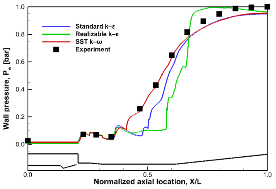
The shear stress transport (SST) k–ω turbulence model is a blended model (made up of a combination of the k–ω and kε turbulence models) and is well known to be accurate and applicable for a wide range of Reynolds numbers. But the SST k–ω turbulence model has no wall function, so the y + needs to be lower to capture the boundary layer. The y + implies a dimensionless wall distance for a wall-bounded flow, and it is extremely important in resolving boundary sublayers. Therefore, the computational grids of the present study were set to y + ≤ 1 near the wall to fit the SST k–ω turbulence model, and the total number of grids was approximately 120,000, based on the subscale diffuser. In order to increase the accuracy of the calculation results, a mesh sensitivity study was performed according to the procedures of previous studies [18]. We performed experiments using a 1/5.6 subscale diffuser operating at a pressure of 50 bar using cold-flow nitrogen. This subscale diffuser was designed through the Reynolds similarity criterion, and we set the same Reynolds number at the diffuser outlet. As shown in Figure 3, the shear stress transport (SST) k–ω turbulence model, which demonstrated the closest agreement with the experimental results, was used for the analysis.
In this model, the transport equations in Equations (6) and (7) were used.
x i ρ k u i = x j Γ k k x j + G k Y k + S k
x j ρ ω u j = x j Γ k ω x j + G ω Y ω + D ω + S ω
Here, G k is the turbulent kinetic energy generated by the average velocity gradient, Γ is the effective diffusivity, and Y is the dissipation term [20].

3. Results and Discussions

3.1. Flow Characteristics According to Operating Pressure P 0 Variations

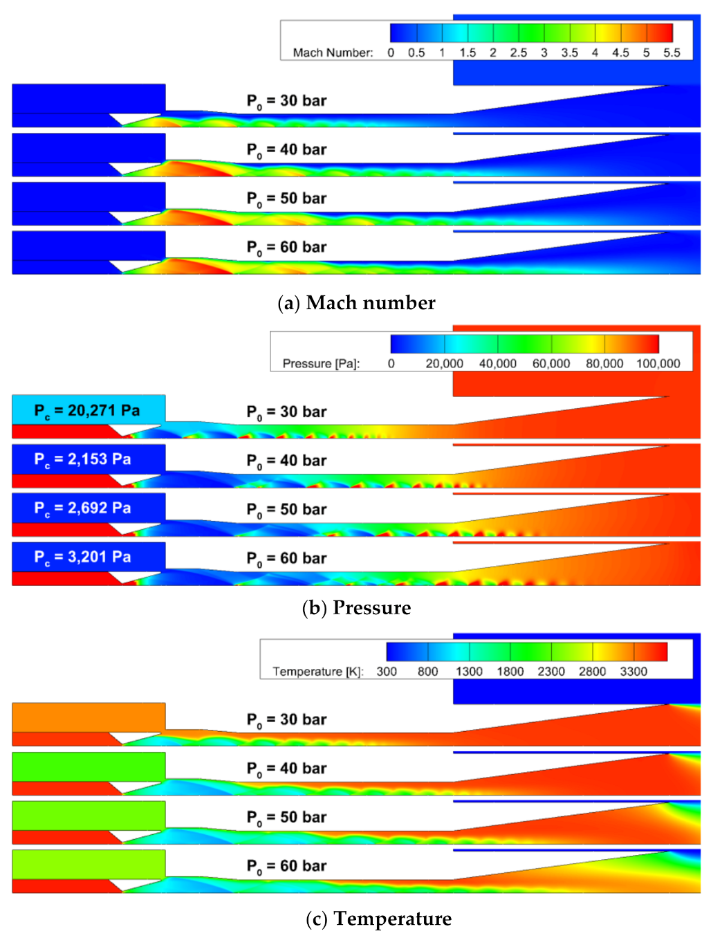
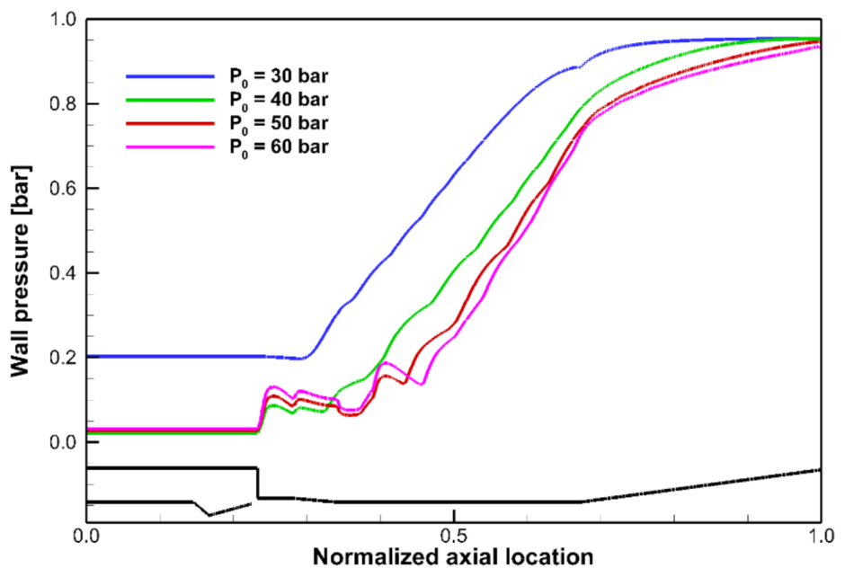
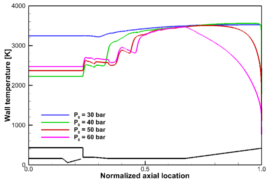
First, the diffuser wall was considered adiabatic, and the variation in the flow characteristics of the diffuser according to the operating pressure was investigated. As shown in Figure 4, Figure 5, Figure 6 and Figure 7, the baseline diffuser was started at a minimum operating pressure of 40 bar, and a low pressure condition of approximately 2000 Pa was simulated in the vacuum chamber. The chamber pressure increased slightly when the operating pressure increased after the diffuser was started [3]. It was found that higher operating pressure caused the supersonic flow from the test nozzle to exhibit a higher momentum; therefore, the diffuser entrance pressure increased, owing to the under-expanded flow. As presented in Figure 5, at an operating pressure of 30 bar, the outlet flow of the test nozzle could not be expanded sufficiently, owing to the relatively high back pressure; therefore, it was separated from the middle wall of the test nozzle. Additionally, a high-pressure region of approximately 20,000 Pa existed inside the vacuum chamber, and the diffuser could not be started sufficiently to simulate a high-altitude condition. Because the diffuser entrance did not attain a fully supersonic flow, the high temperature burnt gas exchanged heat with the air in the vacuum chamber, and the mixed gas (with a temperature exceeding 3000 K) was distributed throughout the diffuser system, as displayed in Figure 5c.
In contrast, when the diffuser was started at an operating pressure of 40 bar, the supersonic flow from the test nozzle outlet was fully transmitted to the diffuser entrance, which extracted air from inside the vacuum chamber. As a result, the vacuum chamber attained a pressure of approximately 2000 Pa, and its temperature became lower than that in the case where the diffuser could not be started. In addition, at 50 and 60 bar, the higher operating pressure increased flow velocity, which increased the size of the low-temperature region because the recirculation flow was pushed back from the second throat to the diverging section, as shown in Figure 5c.

3.2. Flow Characteristics According to Geometric Shape Variations

In this study, we investigated the effect of diffuser entrance length L d (where the supersonic flow is expanded when starting the diffuser), the length ratio of the second throat L s t / D s t (where the transition from supersonic to subsonic flow occurs), and the length of the diverging section L s (where temperature and pressure recovery occurs), as depicted in Figure 1. The dimensions of the baseline diffuser were as follows: L d = 100 mm, L s t / D s t = 8, and L s = 644 mm [18]. Based on these dimensions, investigations were performed under various geometric configurations.

3.2.1. Effects of Diffuser Entrance Length L d

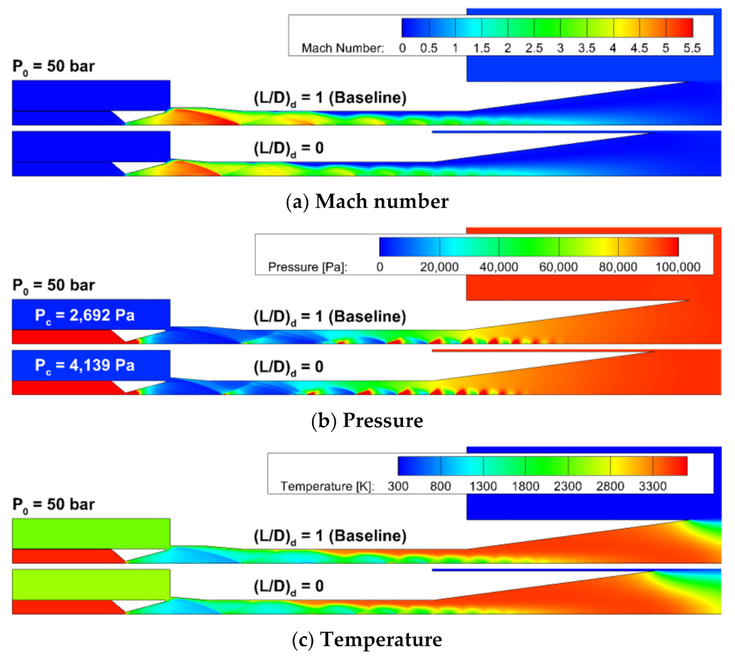
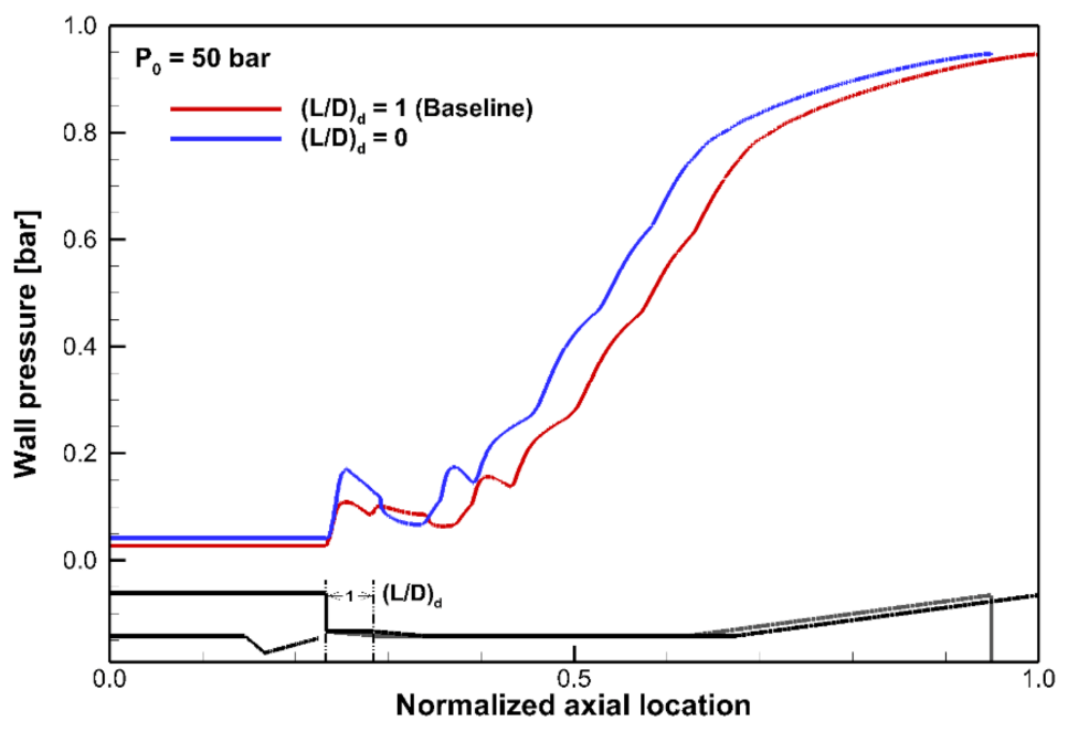
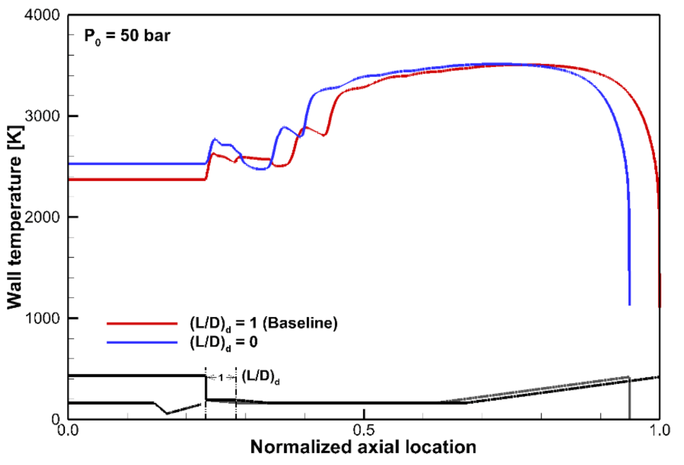
L d / D d represents the ratio of the diffuser entrance length from the nozzle outlet to the converging section with respect to the diameter of the diffuser. This is the section that directly affects plume formation at the exit of the test nozzle in the axial direction because the flow is developed before flow deceleration in the converging section. Analyses were performed under an operating condition of 50 bar for both the baseline diffuser ( L d / D d = 1) and the diffuser without an entrance length ( L d / D d = 0). The results are illustrated in Figure 8, Figure 9 and Figure 10.
When L d / D d is equal to 1, the plume at the exit of the nozzle is sufficiently developed and the vacuum chamber pressure is simulated up to 1646 Pa. In contrast, when L d / D d = 0, the nozzle outlet plume decreases, owing to the abruptly reduced flow path, which also affects the flow inside the second throat. Furthermore, rapidly compressed flows affect the vacuum chamber, resulting in an increase in chamber pressure and temperature. Therefore, the entrance length L d of the diffuser should exceed a certain value for effective low-pressure simulation and stable flow development of the vacuum chamber in the STED.

3.2.2. Effects of Second Throat Length L s t

The second throat is a straight section where the supersonic flow transitions to a subsonic flow, and the flow passes through this section after first decelerating in the converging section. As this section was designed to converge to a Mach number of one, the flow velocity decreased due to frictional and pressure losses from shock waves; therefore, flow separation occurred. These complex flow phenomena directly affected flow characteristics in the diffuser.
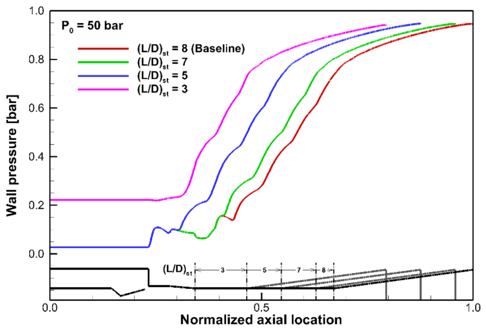
The variations in diffuser wall pressure distributions caused by the changes in L s t / D s t at a pressure of P0 = 50 bar are presented in Figure 11. As L s t / D s t decreased, the length of the diffuser flow that allowed sufficient deceleration decreased as well; this resulted in rapid pressure recovery, which generated large shock waves. Therefore, the separation point of the supersonic flow moved upstream and the ambient effects increased significantly. The separation point of the supersonic flow was determined from streamlines based on the recirculation zone where the axial velocity vector changed to a negative value, obtained near the diffuser wall surface. The cases of L s t / D s t = 7 and 8 (baseline diffuser value = 8) exhibited similar tendencies in flow and wall pressure patterns before separation. However, because the length of the second throat was decreased, the separation point moved upstream gradually, and, subsequently, a sudden pressure recovery occurred after separation. The case of L s t / D s t   = 5 showed that separation occurred just ahead of the second throat. In contrast, in the case of L s t / D s t   = 3, the diffuser did not reduce the pressure of the vacuum chamber because a supersonic flow could not be sufficiently developed, owing to the smaller second throat length; therefore, the ambient back pressure exerted a more prominent effect.
From the above results, we discovered that the length of the second throat must be equal to the value that affords the development sufficient for a supersonic flow. However, a larger second throat length results in more space constraints and an excessively high cooling system capacity. Therefore, it is necessary to select length from within a range that minimizes L s t but does not affect the diffuser flow and its performance.

3.2.3. Effects of Diverging Section Length L s

L s is the length of the diverging section of the diffuser, where the diameter of the diffuser increases after the second throat to recover static pressure and temperature. After the supersonic flow moves into the diverging section from the second throat, it fully transitions to a subsonic flow, and the high-speed flow is decelerated sufficiently to allow for its discharge into the atmosphere without considerable noise and vibrations. To investigate the effect of a change in L s on the diffuser system, its value was changed from that of the baseline model ( L s = 644 mm) to that of the half model ( L s = 322 mm) and then to zero ( L s = 0 mm).
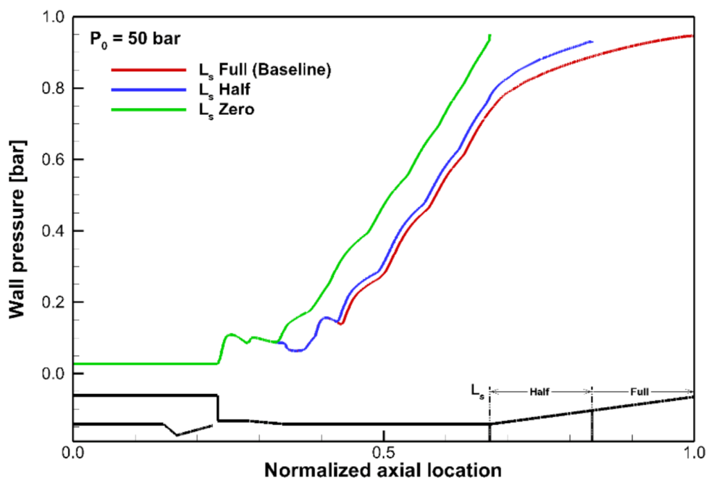
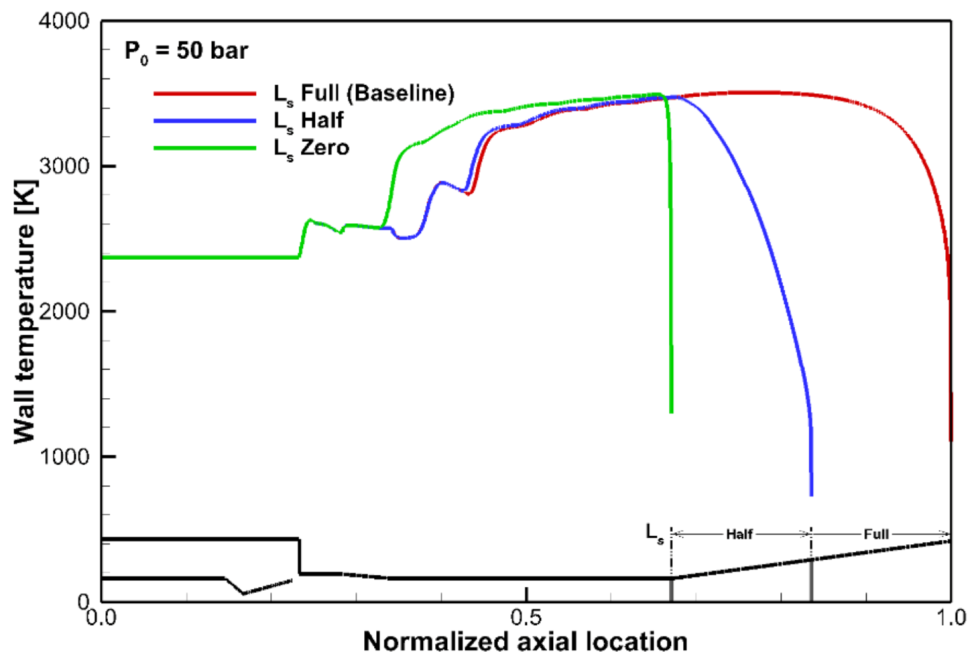
Figure 12 depicts the pressure distribution of the diffuser wall according to the change in L s . In the case of the half model ( L s = 322 mm), the wall pressure did not differ significantly from that of the baseline model ( L s = 644 mm). However, as L s decreased, the supersonic flow did not decelerate sufficiently at the diverging section; therefore, recirculation flow from the atmosphere occurred, owing to flow separation caused by the high-speed flow at the diffuser outlet. This recirculation flow at the diffuser outlet affected the entire diffuser system. A larger recirculation flow resulted in earlier supersonic flow separation and pressure recovery, as shown in Figure 13. In particular, when L s = 0, the strong supersonic flow inside the diffuser continued without any deceleration, except for that resulting from the influence of friction. Consequently, the effects of recirculation flows from the atmosphere became more prominent. The flow separation point moved upstream before the start of the second throat, and the pressure recovered rapidly to ambient pressure. Supersonic flow without sufficient deceleration at the exit can cause severe noise and vibrations in the diffuser system, which can adversely affect the entire system. Therefore, it is necessary to install the diverging section to achieve stability for both the flow and the diffuser system. The diffuser designed in this study should have a diverging section of at least 322 mm in order to ensure that the supersonic flow undergoes sufficient deceleration during transmission.

3.3. Heat Transfer Characteristics with Respect to Operating Pressure

In the previous section, the flow characteristics inside the diffuser were examined while considering the diffuser wall to be adiabatic. A high-temperature region of approximately 2000 K or more appeared at the diffuser wall. Furthermore, it is expected that the diverging section will have a temperature of approximately 3000 K or greater; therefore, a cooling system is required. In this study, a co-flow type cooling channel was added to the wall of the diffuser to determine the heat transfer characteristics of the diffuser. The cooling channel was divided into two sections, as illustrated in Figure 14, and the wall surface of the diffuser and cooling channel was composed of STS 304. The physical properties of STS 304 are listed in Table 3, and the temperature dependence of thermal conductivity was considered. The coolant used was liquid water with a mass flow rate of 2 kg/s [21].
Figure 15 shows the flow characteristics of the diffuser with and without the cooling channel when the operating pressure is 50 bar. After cooling, the flow and pressure distribution characteristics inside the diffuser did not differ significantly from those of the adiabatic condition; however, the temperatures in the subsonic flow section and diffuser outlet decreased by more than 1000 K, owing to wall cooling, which can be clearly observed in Figure 15c.
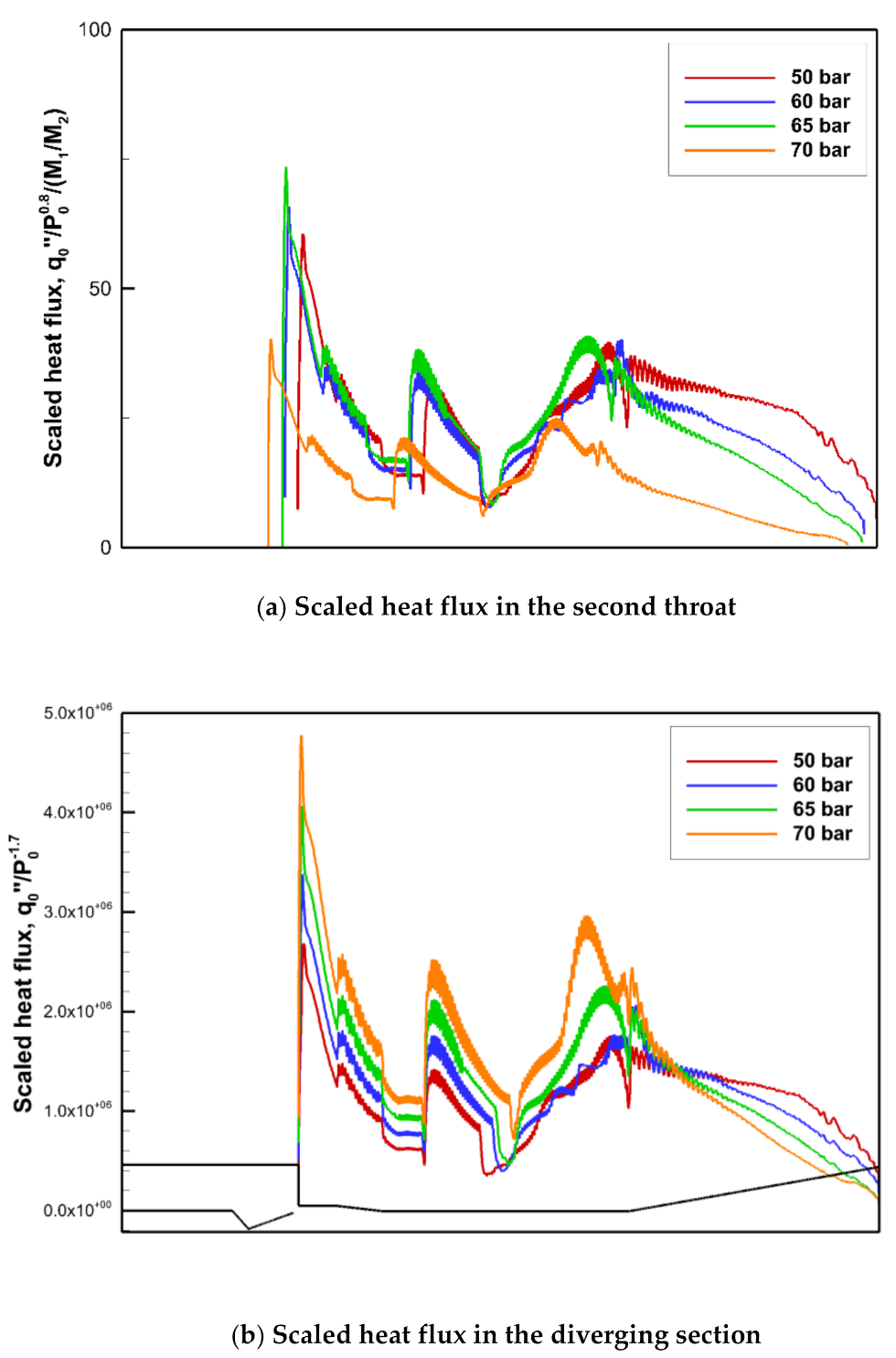
Figure 16 depicts the heat flux from the combustion gas to the wall surface of the cooling water. The supersonic flow generated shock trains that caused repeated pressure increases and decreases at the wall surface, owing to shock waves and reflected waves inside the diffuser. The heat flux at the diffuser wall was large at the diffuser entrance and at the second throat, where the plume expanded from the nozzle and the shock train occurred, respectively. This implies that the heat flux increased when the pressure variation in the diffuser increased. The heat flux exhibited the same tendency as the pressure fluctuation caused by the shock train in the second throat, and it increased gradually in the temperature recovery section, where the supersonic flow transitioned to a subsonic flow.
Figure 16a indicates that the heat flux increases with the operating pressure in the section before the supersonic flow separated from the diffuser wall. Some relatively simple correlations for the calculation of the gas-side heat transfer coefficient have been developed based on experience with turbulent boundary layers [22]. Therefore, we used the Nusselt number in Equation (8), which is generally applied when conducting heat transfer analysis in the design of rocket engines. Under normal circumstances, the heat transfer coefficient varies with the chamber pressure to the 0.8 power, so the following form has been widely used:
N u     R e 0.8 P r 0.34
where N u , R e , and P r are the Nusselt, Reynolds, and Prandtl numbers, respectively.
As presented in Table 2, the thermodynamic properties of the working fluid are similar. Therefore, we assumed that the operating pressure was the most influential factor in terms of heat transfer to the wall surface. The heat flux was divided by P 0 0.8 based on Equation (8). Consequently, the scaled heat fluxes with respect to P 0 in the supersonic section are similar to each other as shown in Figure 16b (i.e., the heat flux of the supersonic flow to the wall surface is related proportionally to P 0 0.8 ). In contrast, the subsonic section exhibits a different tendency from that in the supersonic section because of factors such as the reduced velocity after supersonic flow separation and the recirculation zone from the diffuser outlet.
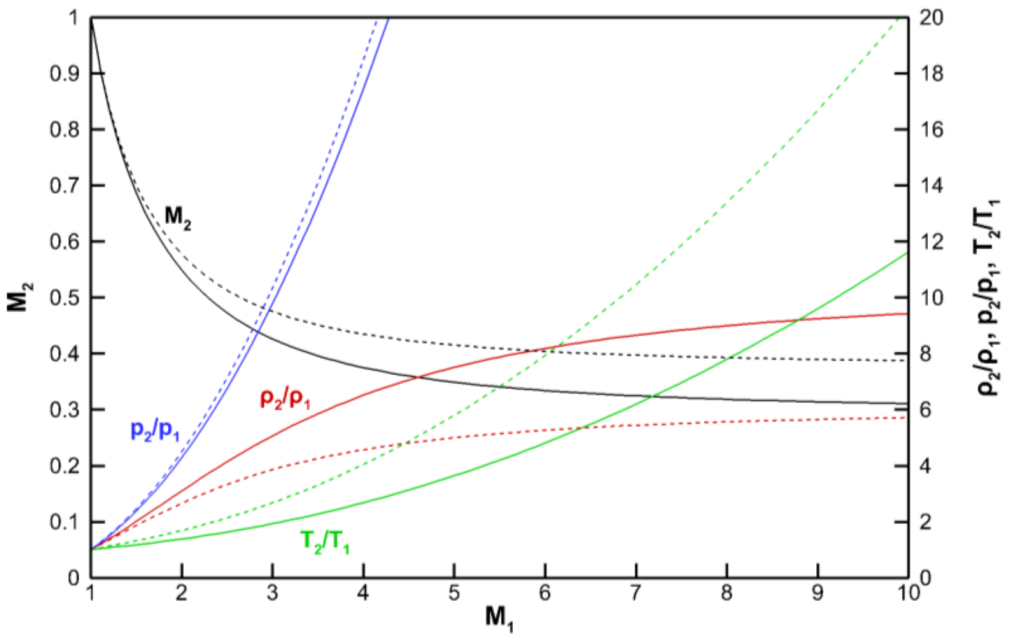
After flow separation, the supersonic and subsonic regions are mixed in the second throat section. Shock trains are formed by shock waves, and, thus, the heat flux on the diffuser wall fluctuates severely. Shock waves and shock trains are believed to exert considerable effects on the heat flux in this region. Therefore, to scale the heat flux with respect to the magnitude of the largest oblique shock wave affecting separation, the heat flux was divided by the Mach number ratio M 1 / M 2 before and after the largest oblique shock wave. The results based on this separation point are presented in Figure 17a. The scaled heat flux after separation increased with a similar tendency, but only a relatively short region at 70 bar was comparable. Because the separation point was approximately located on the downstream side, large oblique shock waves occurred due to the limitation of the second throat length. Because momentum increases as the operating pressure increases, the angle of the oblique shock wave β decreases, and, thus, the Mach number ratio before and after the oblique shock wave decreases. However, at 70 bar, the Mach number ratio increased because large oblique shock waves occurred due to the limitation of the second throat length. We derived the angle of the oblique shock wave through a theoretical equation and confirmed that the results showed a similar tendency (see Table 4). The changes in property across the normal shock wave of the burnt gas used in the theoretical equation are depicted in Figure 18. Additionally, in the diverging section where the subsonic flow occurred, the effect of the recirculation zone from the diffuser outlet became substantial, approximately proportional to P 0 1.7 , as displayed in Figure 17b. In this respect, diffuser cooling should be carefully considered because the temperature in the diverging section is high. Moreover, further studies regarding the heat flux relationship are necessary.

4. Conclusions

A numerical study on the flow and heat transfer characteristics of a STED for high-altitude simulations was conducted. The diffuser designed in this study was started at a minimum operating pressure of 40 bar, and the pressure in the vacuum chamber increased slightly after startup. A recirculation zone occurred at the diffuser outlet as operating pressure increased. When Ld/Dd = 0, the vacuum chamber pressure and the temperature of the diffuser increased and affected the flow inside the diffuser. The second throat length ratio Lst/Dst influenced the development of a supersonic flow inside the diffuser and the diffuser starting pressure. The length of the diverging section Ls changed the supersonic flow inside the diffuser to a subsonic flow and discharged it into the atmosphere. When the length of the diverging section was either extremely short or zero, the supersonic flow, which had a large momentum and demonstrated strong shock waves, was discharged directly into the atmosphere, resulting in the occurrence of a heavy recirculation zone at the diffuser outlet. Noise and vibrations, such as those causing structural problems, can have adverse effects. Therefore, to achieve optimal operating conditions, the supersonic flow from the nozzle exit should be sufficiently developed in the diffuser and must be gradually decelerated in order to achieve stable discharge. Consequently, it was confirmed that the length of each section should be limited in consideration of the facility space or the cooling system capacity; however, the sections should be designed with a sufficient length within a certain range to ensure the stable operation of the diffuser system.
After the diffuser was started, the temperature during supersonic flow was low. Nevertheless, the wall surface temperature of the diffuser exceeded 2000 K, and the diverging section (where the supersonic flow transitioned to a subsonic flow) had a temperature exceeding 3000 K. Adding a cooling system to the diffuser wall reduced the temperature by more than 1000 K, but it did not significantly change the internal flow patterns and pressure distributions. In the section where large pressure variations occurred in the diffuser, the heat flux tendencies from the inside to the wall were similar. So, it is theorized that the tendency of the shock waves and shock trains is to exert considerable amounts of large pressure variation, and the tendency of the heat flux was explained by dividing it into three sections according to the behavior of the shock wave. The first section is the fully supersonic flow region before flow separation by the largest oblique shock wave, the second section is the region where supersonic and subsonic flow coexist due to the shock train after flow separation, and the final section is the diverging section where all flow is completely turned into subsonic flow. It was confirmed that the heat fluxes of the supersonic and subsonic flows in the diffuser were proportional to P 0 0.8 and P 0 1.7 , respectively. In addition, in the second throat region after separation, the heat flux could be scaled to the Mach number ratio M 1 / M 2 before and after the largest oblique shock wave, because the largest shock train affected the heat flux of the diffuser wall. Therefore, in the design process of the diffuser cooling system, the tendency of the heat flux can be predicted in the fully supersonic flow region, the mixed region of the supersonic subsonic flow, and the fully subsonic flow region, which are classified by the pressure variations resulting from the shock waves. In addition, an increase in heat flux with working pressure can be achieved.

Author Contributions

Conceptualization, S.J., K.J.Y. and H.J.K.; methodology, S.J., S.H. and K.J.Y.; validation, S.J., S.H. and K.J.Y.; investigation, S.J., S.H. and K.J.Y.; data curation, S.J., S.H. and K.J.Y.; writing—original draft preparation, S.J., S.H. and H.J.K.; writing—review and editing, H.J.K.; visualization, S.J. and S.H.; supervision, H.J.K.; project administration, H.J.K.; funding acquisition, H.J.K. All authors have read and agreed to the published version of the manuscript.

Funding

This research received no external funding.

Institutional Review Board Statement

Not applicable.

Informed Consent Statement

Not applicable.

Acknowledgments

This research was supported by Chungnam National University (2019–2020).

Conflicts of Interest

The authors declare no conflict of interest.

References

  1. Goethert, B.H. High altitude and space simulation testing. ARS J. 1962, 32, 872–882. [Google Scholar] [CrossRef]
  2. Lijo, V.; Kim, H.D.; Rajesh, G.; Setoguchi, T. Numerical simulation of transient flows in a vacuum ejector-diffuser system. Proc. Inst. Mech. Eng. Part G J. Aerosp. Eng. 2010, 224, 777–786. [Google Scholar] [CrossRef]
  3. Sung, H.G.; Yeom, H.W.; Yoon, S.; Kim, S.J.; Kim, J. Investigation of rocket exhaust diffusers for altitude simulation. J. Propuls. Power 2010, 26, 240–247. [Google Scholar] [CrossRef]
  4. Park, B.H.; Lim, J.; Park, S.; Lee, J.H.; Yoon, W.S. Design and analysis of a second-throat exhaust diffuser for altitude simulation. J. Propuls. Power 2012, 28, 1091–1104. [Google Scholar] [CrossRef]
  5. Annamalai, K.; Satyanarayana, T.N.V.; Sriramulu, V.; Bhaskaran, K.A. Development of design methods for short cylindrical supersonic exhaust diffuser. Exp. Fluids 2000, 29, 305–308. [Google Scholar] [CrossRef]
  6. Chen, F.; Liu, C.F.; Yang, J.Y. Supersonic flow in the second-throat ejector-diffuser system. J. Spacecr. Rocket. 1994, 31, 123–129. [Google Scholar] [CrossRef]
  7. Lim, J.; Park, B.H.; Yoon, W.; Lee, Y. Parametric Investigation on the essential flow factors commanding steady operations of the second throat exhaust diffuser. In Proceedings of the 44th AIAA/ASME/SAE/ASEE Joint Propulsion Conference & Exhibit, Hartford, CT, USA, 21–23 July 2008. [Google Scholar]
  8. Prabakar, S.M.; Panchabudhe, L.M.; Muruganandam, T.M.; Sundararajan, T. A study on the performance characteristics of two-stream supersonic diffusers. Aerosp. Sci. Technol. 2019, 95, 105470. [Google Scholar] [CrossRef]
  9. Fouladi, N.; Farahani, M.; Mirbabaei, A.R. Performance evaluation of a second throat exhaust diffuser with a thrust optimized parabolic nozzle. Aerosp. Sci. Technol. 2019, 94, 105406. [Google Scholar] [CrossRef]
  10. Jia, Y.; Li, Z.; Ye, W.; Xu, W. Numerical and experimental investigation of an adjustable dual-channel supersonic diffuser. Acta Astronaut. 2019, 157, 102–110. [Google Scholar] [CrossRef]
  11. Teh, E.J.; Johansen, C.T. Effect of particle momentum transfer on an oblique-shock-wave/laminar-boundary-layer interaction. Acta Astronaut. 2016, 128, 431–439. [Google Scholar] [CrossRef]
  12. Wei, X.; Xue, R.; Qin, F.; Hu, C.; He, G. Research on shock wave characteristics in the isolator of central strut rocket-based combined cycle engine under Ma5.5. Acta Astronaut. 2017, 140, 284–292. [Google Scholar] [CrossRef]
  13. Mousavi, S.M.; Roohi, E. Three dimensional investigation of the shock train structure in a convergent–divergent nozzle. Acta Astronaut. 2014, 105, 117–127. [Google Scholar] [CrossRef]
  14. Gnani, F.; Zare-Behtash, H.; Kontis, K. Pseudo-shock waves and their interactions in high-speed intakes. Prog. Aerosp. Sci. 2016, 82, 36–56. [Google Scholar] [CrossRef] [Green Version]
  15. Gnani, F.; Zare-Behtash, H.; White, C.; Kontis, K. Effect of back-pressure forcing on shock train structures in rectangular channels. Acta Astronaut. 2018, 145, 471–481. [Google Scholar] [CrossRef] [Green Version]
  16. He, M.; Qin, L.; Liu, Y. Numerical investigation of flow separation behavior in an over-expanded annular conical aerospike nozzle. Chin. J. Aeronaut. 2015, 28, 983–1002. [Google Scholar] [CrossRef] [Green Version]
  17. Wang, C.; Xue, L.; Tian, X. Experimental characteristics of oblique shock train upstream propagation. Chin. J. Aeronaut. 2017, 30, 663–676. [Google Scholar] [CrossRef]
  18. Jeon, J.S.; Kim, W.C.; Yeoun, H.I.; Kim, M.S.; Ko, Y.S.; Han, Y.M. An experimental study on performance of second throat exhaust diffusers of different configuration. Trans. Korean Soc. Mech. Eng. B 2014, 38, 279–288. [Google Scholar] [CrossRef] [Green Version]
  19. Ansys Fluent 14.0: Users Guide. Available online: https://www.scribd.com/doc/140163383/Ansys-Fluent-14-0-Users-Guide (accessed on 10 December 2020).
  20. Ansys Fluent 14.0: Theory Guide. Available online: https://www.scribd.com/doc/140163341/Ansys-Fluent-14-0-Theory-Guide (accessed on 10 December 2020).
  21. Kim, T.W.; Jeon, J.S.; Kim, W.C.; Ko, Y.S.; Kim, S.J.; Han, Y.M. Construction of high altitude test facility for liquid rocket engine. In Proceedings of the Korean Society of Propulsion Engineers Spring Conference, Seoul, Korea, 29–30 May 2014. [Google Scholar]
  22. Huang, D.H.; Huzel, D.K. Modern Engineering for Design of Liquid-Propellant Rocket Engines; American Institute of Aeronautics and Astronautics: Washington, DC, USA, 1992. [Google Scholar]
Figure 1. Geometric configuration and main design parameters of the STED.
Energies 14 00532 g001
Figure 2. The atmospheric domain added for better flow simulation near the diffuser exit.
Energies 14 00532 g002
Figure 3. Diffuser wall pressure at P0 = 50 bar for various turbulence models.
Energies 14 00532 g003
Figure 4. Vacuum chamber pressure of the baseline diffuser for various operating pressures.
Energies 14 00532 g004
Figure 5. Comparisons of the baseline diffuser for various P0.
Energies 14 00532 g005
Figure 6. Wall pressure of the baseline diffuser at various operating pressures.
Energies 14 00532 g006
Figure 7. Wall temperature of the baseline diffuser at various operating pressures.
Energies 14 00532 g007
Figure 8. Comparison of two diffuser entrance length ratios.
Energies 14 00532 g008
Figure 9. Wall pressures of two diffuser entrance length ratios.
Energies 14 00532 g009
Figure 10. Wall temperatures of two diffuser entrance length ratios.
Energies 14 00532 g010
Figure 11. Wall pressures of various second throat length ratios.
Energies 14 00532 g011
Figure 12. Wall pressures with various diverging section length ratios.
Energies 14 00532 g012
Figure 13. Wall temperatures with various diverging section length ratios.
Energies 14 00532 g013
Figure 14. Schematic of the diffuser cooling channel system.
Energies 14 00532 g014
Figure 15. Cooling effects of the baseline diffuser at P0 = 50 bar.
Energies 14 00532 g015
Figure 16. Heat flux characteristics of the baseline diffuser for various P0 at the hot gas-side wall.
Energies 14 00532 g016
Figure 17. Heat flux characteristics of the baseline diffuser after separation.
Energies 14 00532 g017
Figure 18. Changes in property across a normal shock wave (solid: air; dashed: burnt gas).
Energies 14 00532 g018
Table 1. Design parameters of the STED.
Symbol ParameterValue
D d Diffuser entrance diameter (mm)1001
D s t Second throat diameter (mm)80
D e Diffuser exit diameter (mm)250
L c Converging section length (mm)115.217
θ c Converging angle (°)4.95
θ e Diverging angle (°)7.5
L d / D d Diffuser entrance length ratio0, 1
L s t / D s t Second throat length ratio3, 5, 7, 8
L s Diverging section length (mm)0, 322, 644
1 Baseline diffuser dimensions are shown in bold.
Table 2. Properties of the burnt gas used in the study.
P 0
(bar)
T
(K)
C p
(kJ/kg·K)
M
(g/mol)
μ
(kg/m·s)
k
(W/m·K)
303523204422.821.08E-41.5143
403562204722.901.09E-41.4445
503592204922.961.10E-41.3919
603616205123.021.11E-41.3499
Table 3. Properties of solid STS 304.
PropertyValue
Density (kg/m3)8030
Specific heat (J/kg·K)502.48
Melting point (K)1673.15
Conductivity
(W/m·K)
Temp. (K)
293.1515.09
373.1515.22
473.1517.20
573.1518.20
673.1521.04
773.1525.59
873.1530.93
Table 4. Numerical Mach number and theoretical shock angle.
Pressure (bar) M 1 M 2 M 1 / M 2 β (°)
50 3.5411.7552.01818.7
60 3.7562.0421.84017.9
65 3.8402.3641.62416.8
70 3.9711.3732.90018.9
Publisher’s Note: MDPI stays neutral with regard to jurisdictional claims in published maps and institutional affiliations.