Abstract
A small rotating detonation engine (RDE) model and the corresponding experimental setup were constructed for the experimental investigation of the detonation propagation characteristics and thrust performance of a circular RDE. Experiments were conducted at a range of 0.3–2.5 equivalence ratio with a total mass flow rate of less than 180.0 g/s using a C2H4/O2 mixture. Irregularly unstable detonative combustion occurs immediately after the detonation initiation, which includes initiation, propagation, decaying, and the merging of detonation waves. Following this, periodically unsteady detonative combustion occurs in the circular channel, resulting in the stable operation of the RDE. During stable operation, two detonation waves are predominant, rotating along the wall at a speed lower than the Chapman–Jouguet (CJ) detonation speed. The characteristic velocity efficiency is approximately 73% on average. The low characteristic velocity efficiency is presumed to be caused by the unoptimized combustion channel and the poor mixing efficiency owing to the two-dimensional injector configuration. The effect of the RDE component design and the RDE flow field characteristics need to be further investigated for improving the performance of the RDE.
1. Introduction
Pressure gain combustion (PGC) is a method to improve the performance of thermodynamics engines. Detonation engines are considered a promising means of realizing PGC and have been actively studied for the past few decades. Pulse detonation engines (PDE) and rotating detonation engines (RDE) are the most well-known among several types of detonation engines. Each of these engines implement constant volume combustion gas-dynamically without having any moving parts or other mechanical complexity. PDE and RDE are compared in Table 1.
A PDE is a pulsed engine or combustor consisting of a long tube, where one end is open, but the other end is closed. The realistic demonstration of a PDE has been attempted several times. The U.S. Air Force Research Laboratory conducted a flight test with a PDE by using a modified Long E-Z aircraft equipped with a PDE developed by them [1]. Kasahara’s team at the University of Tsukuba (2009) and Nagoya University (2015) exhibited single and quad-tube rocket-type PDEs via ground and flight demonstrations [2,3]. In 2011, General Electric conducted a performance test of a gas turbine system based on a pulse detonation combustor [4]. Currently, given the physical and performance limitations of low-frequency pulsed operations, PDEs are used in applied areas or propulsion subsystems such as thermal sprays [5], reaction control systems [6,7] and combustion wave igniters [8,9], rather than as the main propulsion systems. However, they continue to be used for the study of detonation physics. Roy et al. [10] summarized several PDE technologies developed before 2014 and discussed detonation propulsion, the realistic implementation of a detonation-based thermodynamic cycle, and certain technical limitations such as the propellant supply, mixing, and initiation.

Table 1.
Comparison of the typical characteristics of rotating detonation engines (RDEs) and Pulse detonation engines (PDEs).
Table 1.
Comparison of the typical characteristics of rotating detonation engines (RDEs) and Pulse detonation engines (PDEs).
| PDE (or PDC) | RDE (or RDC) | |
|---|---|---|
| Combustor Type | Cylindrical | Circular |
| Initiation Event | Periodic | Single |
| Propagation Mode | Periodic | Continuous (self-sustained detonation) |
| Operation Frequency | 0.01–1.0 kHz [11,12] (depending on length and response time of supply system) | 1.0–100.0 kHz [13] (depending on circumferential length and the number of detonation waves) |
| Detonation Speed | Close to CJ detonation speed | Lower than CJ speed |
| Application | Propulsion, Thermal spray, Reaction control system, Combustion wave igniter | Propulsion, Combustor |
During the last decade, most efforts on detonation-based PGC studies shifted their attention to RDEs owing to their continuous operation characteristics in annular combustors, which are geometrically similar to those in aviation gas turbine combustors. The concept of RDEs was introduced in the 1960s [14], but attracted renewed interest in the mid-2010s [15] as an alternative to PDEs. Figure 1 shows the unwrapped two-dimensional schematics of the combustion flow field in an RDE combustor. The general configuration of an RDE comprises an annular channel where detonation waves run in a circumferential direction continuously, by consuming the incoming fuel and oxidizer. Thus, the RDE is similar to the open-type combustor, whereas the PDE is closer to the closed-combustor. Basically, the RDE, also known as a rotating detonation combustor, is a detonation-driven combustor, but it is more commonly referred to as a rotating detonation “engine” because it can produce thrust owing to the compression effect produced by the detonation.
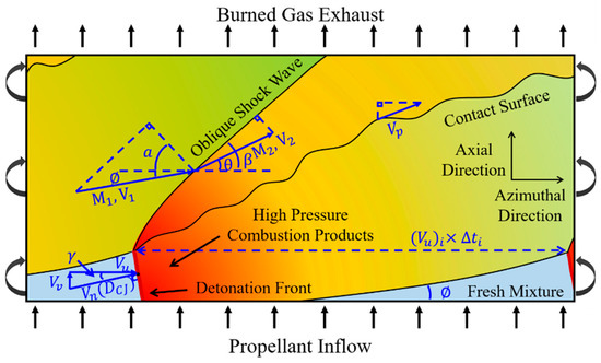
Figure 1.
Schematics of flow field in an RDE based on the standing detonation.
Several experimental [14,15,16,17,18,19,20,21,22,23,24,25,26,27,28] and computational [18,29,30,31,32] studies during the past decade have focused on the detonation physics inside the RDE, the stabilization of its operation characteristics, and the enhancement of its performance, but further efforts are needed for better understanding. The present study aims to understand the operational characteristics of small-scale rocket-type RDEs. An RDE having a new design is built and tested to investigate the modes of detonation propagation for a range of mass flow rates around the stoichiometric condition. Performance enhancement using a 30° conical center body (expansion nozzle) is also examined at a range of 0.3–2.5 equivalence ratio.
2. Experimental Methods
2.1. Detonation Cell Width and Initiation Energy
Detonation cell width () is an important parameter in determining the minimum combustion channel size and initiation energy required to construct an RDE. The detonation cell width is affected by the mixture type and the initial conditions. The detonation cell width of oxygen-based RDEs is 1/10th that of air-based RDEs. Table 2 lists the detonation cell widths for a C2H4/O2 mixture obtained experimentally by previous researchers. The detonation cell width for the C2H4/O2 mixture under the stoichiometric condition is approximately 0.50–0.80 mm. The relationship between the detonation cell width and the initiation energy according to the mixture type was summarized and shown by Schauer et al. [33]. The minimum initiation energy for the C2H4/O2 mixture is approximately 100 mJ.
Table 2.
Detonation cell width at 0.1 MPa and 298 K.
2.2. RDE Model Configuration
A small uncooled RDE with an unmixed supply of fuel and oxidizer for hundreds of milliseconds of test time is considered for a simple lab-scale experiment. Similar experimental models and conditions are summarized in Table 3. As it is difficult to discuss the pros and cons of each experiment in detail, the RDE model by Hansmetzger et al. [16] is focused on in this study, which employs slot injectors for fuel and oxidizer. This model has the slot injectors formed by the gap between the combustor parts, resulting in the simplest configuration and lowest-cost fabrication of the RDE test model. In the present study, the slot type injectors are used for the fuel as well as the oxidizer, although the combustion efficiency and performance are expected to suffer a little. Figure 2 shows the CAD drawing of the RDE model for this study.
Table 3.
Specifications of RDE models developed by other research groups.
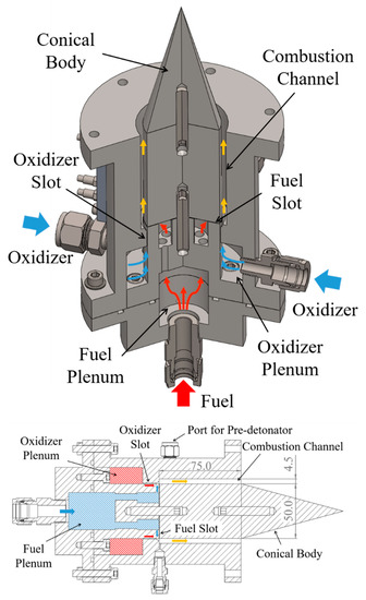
Figure 2.
Configuration of RDE model (unit: mm).
Gaseous fuel (C2H4) and oxidizer (O2) are injected from the feed plenum to the annular combustor though 0.3 mm and 0.46 mm slots, respectively. The inner diameter of the combustor channel is 50.0 mm, the channel width is 4.5 mm, and the combustor length is 75.0 mm. The mechanical throat is not considered in this study for direct visualization inside the combustor. The conical center body of 30.0° is optionally attachable at the exit of the combustor, enabling a performance comparison between the buff exit and conical center body. A small single-tube PDE [8] using the same fuel and oxidizer is installed tangentially at the combustor channel as a pre-detonator for detonation initiation in the RDE. The inner diameter and length of the pre-detonator tube are 4.0 mm and 150.0 mm, respectively. A Shchelkin spiral is not employed for flame acceleration and deflagration to detonation transition (DDT) in this tube, because the detonation initiation energy is smaller by several orders of magnitude (approximately 1/10,000), the detonation cell width is 1/10th smaller, and the DDT distance is much smaller, for an oxygen-based mixture than an air-based mixture.
The maintenance of self-sustained detonation in the RDE combustion channel is important. This requires the minimum combustion channel diameter, length, and width to be determined by considering the mixture and operation conditions. Bykovskii et al. [15] suggested a correlation between the combustion mixture layer and the geometric variable expressed as a function of the well-known detonation cell width, as presented in Equations (1)–(4):
Here, is the geometric parameter. All circular RDEs using a gaseous oxidizer have a constant value for K, i.e., K = 7 2.
Table 4 lists the minimum shape size of the combustion channel for the C2H4/O2 mixture, calculated from Equations (1)–(4). The present RDE model satisfies the minimum shape size and is sufficient to maintain self-sustained detonation.
Table 4.
Minimum dimensions of the RDE combustion channel using C2H4/O2.
Figure 3 shows the experimental setup of the test equipment. Static pressures at the feed line, fuel and oxidizer supply, combustor channel, and pre-detonator are measured using a 2.0 kHz pressure transmitter (Keller PAA-23SY, 5.0 MPa 0.25% full scale). A dynamic pressure sensor (PCB 113B26, 3.45 MPa 1.0% F.S.), which can measure characteristic frequencies higher than 1.0 MHz, is used to investigate the detonation propagation characteristics and to calculate the detonation speed. The dynamic pressure sensor is installed at the combustor outer wall 3.0 mm downstream from the combustor head with a 4.0 mm recess. The recess is intended to minimize physical damage and electric signal error by avoiding exposure to the hot combustion product. The recess length is selected within L/D, here acoustic resonance does not occur. A 10.0 kHz load cell (Cas SBA-100L, 100.0 kgf 0.01% F.S.) is installed to measure the dynamic thrust. K-type sheath thermocouples, each having a 1.6 mm diameter, are used to check the temperatures of the fuel, the oxidizer, and the combustor outer wall. The purpose of using thermocouples is not to obtain instantaneous results, but to obtain average data through repeated experiments under the same conditions, and to measure the temperature of cold gas for mass flow rate. The main purpose of using the thermocouples is to obtain average data through repeated experiments under the same conditions. The measured data are acquired using a Yokogawa DL850E ScopeCoder, wherein the data sampling rate is set to five times based on the dynamic pressure sensor. A visualization of the detonation wave rotating inside the combustor is captured using a Phantom v2512 mono-type high-speed camera with a Nikon 80–400 mm lens. The high-speed camera is located 5.5 m downstream from the combustor exit.
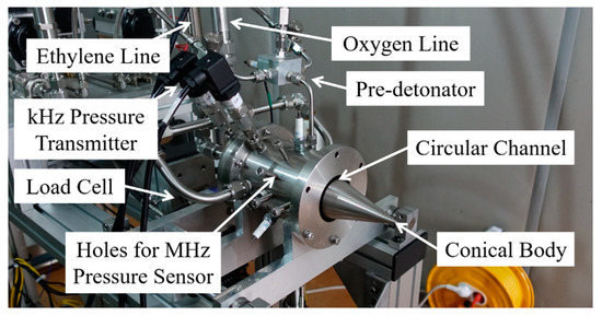
Figure 3.
Experimental setup.
2.3. Experimental Procedure
Experiments are conducted after determining the response characteristics of the fuel and oxidizer supply system and the experimental model. The operational sequence is controlled by a programmable logic controller (PLC). Figure 4 shows the results of pressure variations at major locations operated by the sequence. During the initial period (1), the propellant supply begins and the pressure reaches a steady state in the propellant supply plenum chambers and combustors. The pre-detonator initiates at the beginning of period (2). The detonation is initiated in the RDE combustion channel during period (3). The hot fire combustion test begins during period (3) and continues through periods (4), (5), and (6). A steady state is obtained at the beginning of period (5) at the main combustor channel. Pressure in the propellant supply plenum chambers decreases during period (6), and the hot fire combustion test terminates. Purging occurs during period (7). Separate tests were conducted for thrust measurement, lasting for approximately 0.6 s, and for dynamic pressure measurements lasting for approximately 0.2 s. The test time is reduced for dynamic pressure measurement to protect the pressure sensor from the thermal load, as no cooling is being applied yet for the sensor. The test time for the thrust measurement was selected to be three times that of the dynamic pressure measurement, because a sufficiently long test time is required to get a reliable average thrust.
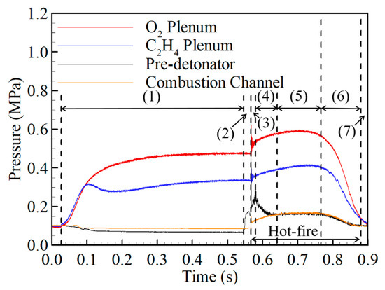
Figure 4.
Pressure history with experimental events.
2.4. Mass Flow Rate
The mass flow rates of the fuel and oxidizer are measured in a classical manner. The mass flow rates are estimated by measuring the weights of gas cylinders before and after the cold flow test [17]. Gas cylinders of 3.4 L (initial pressure is approximately 10 MPa) and precision balance (A&D GP-20K, 21.0 ± 0.001 kg) were used for the measurement. Experiments for the estimation of mass flow rate were conducted three times for 1.5 s for every RDE under supply pressure conditions less than 0.8 MPa, and the results are plotted in Figure 5. The error bar is not plotted in this figure because the errors are smaller than the sizes of the symbols in this figure, except in the case of 0.2 MPa. The results for the mass flow rates are compared with the theoretical estimation obtained by assuming isentropic flow. The deviations are 12.4% and 8.2% for fuel and oxidizer, respectively. The maximum error was found for the case of 0.2 MPa supply pressure, but was less than 10% in all other cases. During the combustion experiment, the mass flow rate is obtained by using the fitted curve of Figure 5. Combustion experiments were conducted in cases where the mass flow rate is confirmed, and where the total mass flow rate is less than 180 g/s. In addition, experiments for the investigation of the detonation propagation characteristics were conducted under the near-stoichiometric condition, while the thrust performance was examined for a range of equivalence ratios from 0.3 to 2.5.
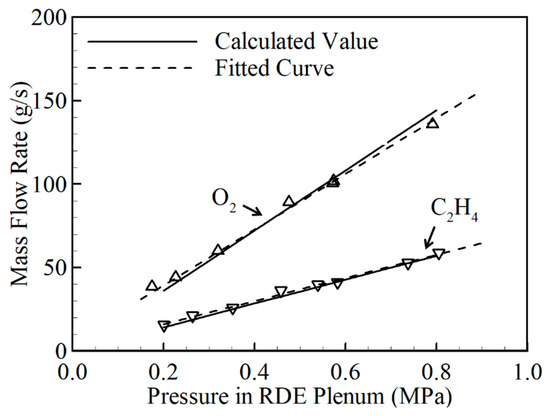
Figure 5.
Comparison of measured and calculated mass flow rates.
3. Detonation Wave Propagation Characteristics in RDE
3.1. RDE Initiation Characteristics
Figure 6 is the pressure record obtained by the dynamic pressure sensor of the RDE combustor channel for the case where = 64.4 g/s and = 1.03. It is regarded as one of the typical results, where the total duration is 180 ms from detonation initiation to extinction, which varies slightly with the supply pressure. The initial variation is plotted in Figure 6a. A strong shock wave arises just after the initiation from the pre-detonator, and the detonation wave begins to rotate after approximately 0.5 ms. Specific events and visualization images during this phase are plotted in Figure 7.
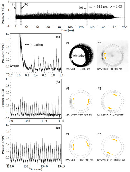
Figure 6.
Pressure record obtained from dynamic pressure sensor at = 64.4 g/s, = 1.03: (a) detonation initiation and transition; (b,c) stable detonation propagation.
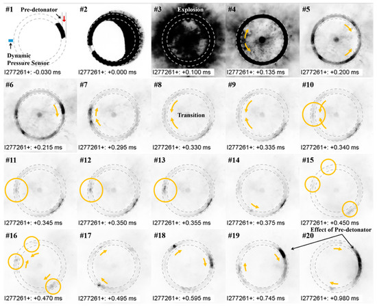
Figure 7.
Snapshots of the detonation initiation and transition process captured at 256 × 256 resolution and 200 kilo-frames per second (kfps). The event times and experimental conditions correspond to Figure 6a.
The flow field experiences strong effects from the shock wave between initiation and 0.15 ms, shown in snapshot #4 and #5, followed by irregular rotating detonation wave motions. Counter-rotating detonation waves develop but merge into a single detonation wave rotating clockwise at 0.215 ms, shown in snapshot #6. An additional detonation wave develops ahead of the main detonation wave, two detonation waves rotate as shown in snapshot #7 at 0.295 ms, but shortly decay within 0.035 ms, and the single detonation wave rotates counterclockwise from 0.330 ms for a duration of 0.025 ms, as shown in #8 through #13. The unstable and irregular processes continue up to 0.8 ms after the initial operation begins, including the initiation, propagation, decaying, and merging of detonation waves, although the stable detonation wave propagation is desirable for the normal operation of the RDE. Detonation wave propagation is an unstable process involving fluid mechanics, but the regular propagation of the detonation wave is considered stable for an RDE.
It would be assumed that the detonation initiated in the pre-detonator may propagate through the annular channel tangentially. However, an examination of the result of the initial phase shows that this concept is unacceptable because of the large differences in cross-section areas between the pre-detonator and RDE combustor channel. The results of this study suggest the following two facts. The first fact is the presence of a transition period of detonation initiation in RDE. The process of detonation initiation and the development of a flow field are complex and depend on the geometry of the combustion channel, the mixing efficiency of fuel and oxidizer, the initial conditions, and the characteristics of the pre-detonator. In particular, the strength of the strong shock wave and the delay time are largely determined by the impulse, depending on the initial conditions and geometry of the pre-detonator and the combustion channel [21,22]. The second fact is that the pre-detonator is simply a high-energy supply device used to initiate the detonation rotating in the RDE combustion channel. In the present model, the pre-detonator is installed in a direction tangential to the cross-section of the RDE combustion channel, but the installation direction of the pre-detonator does not seem to have a perceptible effect on the detonation propagation. In the actual RDE experiment, in addition to the cases [19,22,23] wherein the pre-detonator is installed in a direction tangential to the cross-section of the RDE, there are cases [9,16] in which a successful experiment was conducted by installing it in a vertical direction. Furthermore, a spark plug [14,22] and glow-wire [24] are sometimes used instead of a pre-detonator. Figure 6b,c show the pressure of the stable detonation waves rotating in the combustion channel. The pressure of the detonation waves shown in Figure 6b is relatively low, which is considered to be because of the heat loss and operation of the pre-detonator. The initial conditions of the RDE are inevitably affected because the fuel and oxidizer used to operate the pre-detonator are supplied by branching from the main supply system of the RDE. The effect of decreasing the pressure of the detonation waves lasts approximately 20.0 ms after the detonation initiation. The pressure change related to the pre-detonator is shown in period (3) of Figure 4.
3.2. Regular Operation Characteristics
Figure 8 shows the detonation propagation characteristics related to the change in total mass flow rate under stoichiometric conditions ( = 1.0 ± 0.05). The dominant frequencies were investigated using fast Fourier transform (FFT) and short-time Fourier transform (STFT). The behavior of the detonation waves was identified using images captured at a 256 × 256 resolution and 200 kfps. The behavior of the detonation waves related to the total mass flow rate is as follows. Figure 8a shows a state in which the irregular detonation waves propagate during the combustion time, and a series of processes of the initiation, propagation, decaying, and merging of the detonation waves continues. As shown in the pressure record at the top of Figure 9, irregular behavior with changes in pressure and speed (time difference between waves) occurs continuously. In Figure 8b,c, two stable detonation waves are shown propagating. In Figure 8d, two stable detonation waves are mostly shown to propagate, but three stable detonation waves were temporarily captured on two occasions after the irregular detonation waves propagated (after approximately 95 ms), as shown in the STFT result (yellow arrow) and the pressure record at the bottom of Figure 9. The number of detonation waves is known to depend on the diameter of the combustion channel and the influent mass flux of the fuel and oxidizer [15,29].
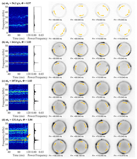
Figure 8.
Comparison of the detonation behaviors under different conditions through fast Fourier transform (FFT), short-time Fourier transform (STFT), and a snapshot captured at a 256 × 256 resolution and 200 kfps: (a) unstable waves; (b) two stable waves; (c) two stable waves; (d) two stable waves and three temporally stable waves.
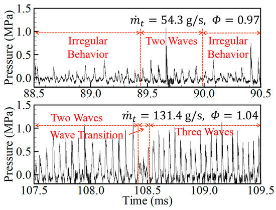
Figure 9.
Pressure history shown in Figure 8a,d.
Wolanski [30] presented a simplified equation that can predict the number of detonation waves, as shown in Equation (5) below. It is expressed as the ratio of the rotation time of the detonation wave and the time required to form the combustion mixture height. It is an expression for RDEs with a circular combustion channel.
Table 5 lists the predicted detonation wave number at the experimental condition of Figure 8. In order to use the previously obtained detonation cell width, the conditions for calculation are assumed to be room temperature and room pressure. Although the predicted detonation wave number is approximate, it shows that the number of detonation waves can be predicted sufficiently accurately if the detonation cell widths for the operating conditions of the RDE are accurately known.
Table 5.
Predicted detonation wave number.
Table 6 lists the dominant flow field frequencies and the detonation speed for the experimental conditions shown in Figure 8. The CJ detonation speed was also calculated and presented. The detonation speed has a large deficit compared to the CJ detonation speed, but the dominant flow field frequency and detonation speed increased slightly as the total mass flow rate increased. As mentioned earlier, the increase in speed is not due to the flame acceleration, which further stabilizes the detonation by obtaining a closed combustion chamber-like effect. The increase occurs because the stagnation pressure in the combustion channel increases as the total mass flow rate increases.
Table 6.
Flow field frequency and detonation speed for each case shown in Figure 8.
3.3. Detonation Wave Speed in RDE
The dominant flow field frequency for the experimental condition in Figure 6 is 16,670–16,980 Hz. The ideal speed and frequency for the same conditions calculated using NASA CEA are 2388 m/s and 12,883 Hz (one wave), respectively. The result and visualizations indicate that two detonation waves with a very large velocity deficit rotate along the outer wall of the combustion channel. The velocity deficit is usually caused by heat and friction losses, but even if these are accounted for, the velocity deficit is very large. This phenomenon has been observed not only in this RDE experimental model but also in all experimental studies on RDEs. As mentioned in the introduction, the geometry of the RDE near the open combustion chamber and the shape of the injectors are considered to be the dominant factors in the detonation velocity deficit. This geometry causes the presence of the axial velocity component of detonation and the low static pressure in the combustion channel, derived from the shape optimization of the combustion channel, nozzle, and injector. As shown in Figure 1, a detonation near the injector propagates in the direction of the combustion mixture, and this detonation wave forms an inclination of the detonation wave in the direction of the combustion mixture via the boundary condition. Therefore, the detonation wave does not rotate along the outer wall at a speed close to the ideal CJ detonation speed (Vn), but rotates at a speed close to the azimuthal velocity component (Vu), excluding the axial velocity component (i.e., momentum loss). In addition, unlike a PDE, detonation does not propagate in a relatively confined environment, so the boundary condition close to the open combustion chamber is considered to affect the detonation propagation in the RDE. Not only are the stagnation pressure and detonation speed increased simply by increasing the influent mass flux [15], but the results in Figure 8 and Table 5 indicate that the detonation speed also slightly increases as the total mass flow rate increases. In order to achieve a high stagnation pressure in RDEs, several researchers applied convergent-divergent nozzles at the end of combustor [17,23,25] by which reduced velocity deficits could be achieved [17,23]. Finally, the slot-type injector makes it difficult to achieve a high mixing efficiency of fuel and oxidizer. In order to improve the static pressure (i.e., combustion efficiency) in the combustion channel, the optimized injector is essential.
4. RDE Performance
In order to analyze the RDE’s performance, the average thrust, specific impulse (), and characteristic velocity efficiency () were investigated. The specific impulse and characteristic velocity efficiency were calculated through Equations (6)–(8) below. In order to calculate the ideal stagnation pressure in the combustion channel, Equation (9) was used and the related properties were obtained through NASA CEA.
The time-averaged static pressure in the combustion channel was investigated as shown in Figure 10. In order to use the RDE as a thruster rather than as a simple combustor, choked flow at the exit of the RDE is necessary. The present choking condition in the RDE is the orange area, which is above the mass flow rate of approximately 107.3 g/s ( = 2.68)–150.6 ( = 0.32). For more meaningful and valid thrust performance, the experiment should be performed in the orange area.
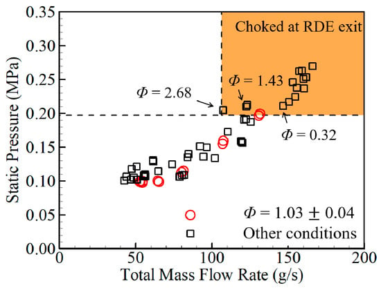
Figure 10.
Time-averaged static pressure in the combustion channel.
Figure 11 shows the thrust record with or without a conical center body at the bluff exit of the RDE. The thrust fluctuation during the combustion time is caused by a strong impulse occurring immediately after the detonation initiation. The load cell and the RDE model are physically fastened, and a heavy load, preloaded to minimize the occurrence of thrust fluctuations, is applied, but the limitations still exist. In order to obtain thrust in a steady state, the combustion time must be increased, but ablation occurs around the holes in the walls of the combustion channel for the measuring unit and pre-detonator, as shown in Figure 12c. As this ablation occurs within a very short time, it is difficult to secure extra combustion time. The ablation around the holes in the walls of the combustion channel is considered to occur owing to the formation of the recirculation zones, which form a high-speed and high-temperature flow field. In addition, the present RDE model was composed of free-cutting steel (SUS303) material for workability, and the properties of this material are considered to cause the ablation.
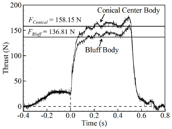
Figure 11.
Thrust history at = 160.9 ± 0.9 g/s, = 0.471 ± 0.005.
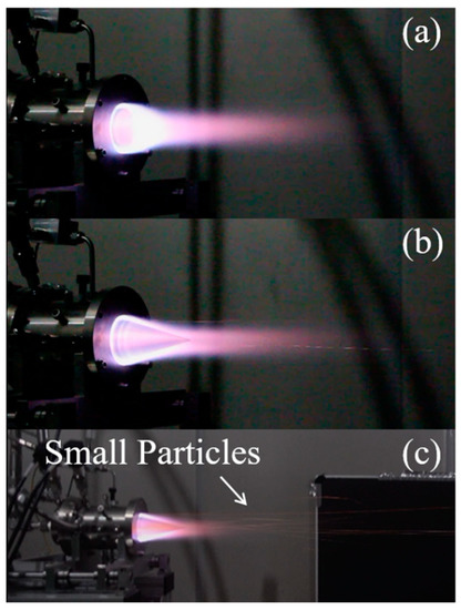
Figure 12.
Pictures of RDE plume: (a) with bluff body at = 152.6 g/s, = 0.45; (b) with conical center body at = 163.0 g/s, = 0.47; (c) small particles owing to the ablation (3840 × 2160 resolution using Sony RX-100M5 camera).
When the conical center body was used, the average thrust and specific impulse increased approximately 21.34 N and 12.50 s, respectively, compared to when the bluff body (non-conical center body) was used. Figure 13 shows the specific impulse related to the presence of the conical center body under various mass flow rate conditions. The application of a conical center body increases the specific impulse by a maximum of 14.08 s.
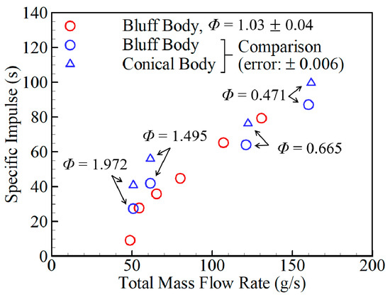
Figure 13.
Specific impulse.
Figure 14 shows the characteristic velocity efficiency expressed as the ratio of the ideal and measured characteristic velocity, suggesting that the increase in thrust and specific impulse related to the presence of a conical center body is not a result of an increase in the total mass flow rate (blue symbols). The application of the expansion nozzle of 30.0° did not dramatically improve the thrust and specific impulse. However, it has a positive effect on the thrust performance. Therefore, the nozzle is necessary to achieve meaningful and valid thrust performance.
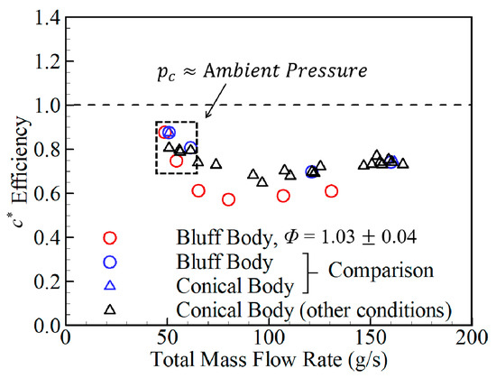
Figure 14.
Characteristic velocity efficiency.
The characteristic velocity efficiency of the present experimental model is, on average, 73%. NASA CEA code and isentropic relations were used to determine the ideal characteristic velocity. Some error would be unavoidable, as the ideal calculation via the NASA CEA code is for a constant pressure rocket combustor, and does not consider the RDE characteristics. Nevertheless, as can be seen via Figure 14, the loss is very large, even considering these errors. As mentioned earlier, this loss is not a phenomenon observed only in this RDE experimental model. The optimum design of the injector must be employed to improve the static pressure (i.e., combustion efficiency) in the combustion channel.
5. Conclusions
A small circular RDE and experimental setup were constructed to experimentally investigate the detonation propagation characteristics and thrust performance. The experiment was conducted using a C2H4/O2 mixture in a range of equivalence ratio from 0.3 to 2.5, with a total mass flow rate less than 180 g/s. The results of the observations made through this study are summarized as follows.
- Immediately after the detonation initiation, an irregular flow was temporarily formed that repeats a series of processes of initiation, propagation, decaying and merging of detonation waves, though periodically unsteady flow should be formed in the combustion channel for the stable operation of RDE.
- Under the experimental conditions, the number of detonation waves rotating along the outer wall of the combustion channel was predominantly two. Three stable detonation waves were temporarily captured at the mass flow rate of 131.4 g/s.
- The number of detonation waves is within the predicted range by comparing the number of detonation waves obtained by the prediction equation. The empirical prediction equation is considered a useful tool for predicting the number of waves in the RDE.
- The detonation speed rotating along the outer wall of the combustion channel is always lower than the CJ detonation speed. The velocity deficit is considered to be the result of lower heat addition rather than the ideal case, which is caused by incomplete combustion, itself caused by poor mixing, which occurs because the two-dimensional injector is not the optimized configuration. In addition, the open-type unchoked combustor channel and the inclination of detonation wave are considered an additional source of velocity deficit.
- The thrust and specific impulse were slightly increased by applying an expansion nozzle of 30.0°. The characteristic velocity efficiency shows low values as the static pressure in the combustion channel stays low.
In order to improve the performance of the RDE, it is necessary to investigate the effects and characteristics of each component of the RDE, and understand the characteristics of the flow field of the RDE. The characteristics of RDE operation and detonation propagation obtained through this study are expected to be useful in future studies.
Author Contributions
Conceptualization, J.-Y.C. and H.-S.H.; methodology, H.-S.H. and E.S.L.; investigation, H.-S.H. and E.S.L.; writing—original draft preparation, H.-S.H.; writing—review and editing, J.-Y.C.; visualization, H.-S.H.; supervision, J.-Y.C.; project administration, J.-Y.C.; funding acquisition, J.-Y.C. All authors have read and agreed to the published version of the manuscript.
Funding
This research received no external funding.
Institutional Review Board Statement
Not applicable.
Informed Consent Statement
Not applicable.
Data Availability Statement
Not applicable.
Acknowledgments
This work was supported by the Space Core Technology Research Grant (NRF-2018M1A3A3A02065563) and Senior Research Grant (NRF-2019R1A2C1004505) through the National Research Foundation (NRF) of Korea, funded by the Ministry of Science and ICT (MSIT) of the Republic of Korea Korean Government. Publication of this paper is supported by BK21FOUR program through NRF funded by MSIT.
Conflicts of Interest
All authors declare that there is no conflict of interest.
Nomenclature
| throat area | |
| Chapman–Jouguet | |
| characteristic velocity | |
| inner diameter of combustion channel | |
| outer diameter of combustion channel | |
| thrust | |
| F.S. | full scale |
| gravity | |
| height of combustion mixture layer | |
| specific impulse | |
| optimal length of combustion channel | |
| total mass flow rate | |
| detonation wave number | |
| stagnation pressure | |
| gas constant | |
| time | |
| temperature | |
| detonation speed | |
| equivalence ratio | |
| characteristic velocity efficiency | |
| specific heat ratio | |
| detonation cell width | |
| width of combustion channel | |
| specific volume for mixture | |
| Subscripts | |
| combustion channel | |
| ideal | |
| measured | |
| maximum | |
| minimum |
References
- Barr, L. Pulsed Detonation Engine Flies into History. Press Release, Air Force Material Command. Available online: https://www.af.mil/News/Article-Display/Article/123534/pulsed-detonation-engine-flies-into-history/ (accessed on 16 May 2008).
- Kasahara, J.; Hasegawa, A.; Nemoto, T.; Yamaguchi, H.; Yajima, T.; Kjima, T. Performance Validation of a Single-Tube Pulse Detonation Rocket System. J. Propuls. Power 2009, 25, 173–180. [Google Scholar] [CrossRef]
- Matsuoka, K.; Morozumi, T.; Takagi, S.; Kasahara, J.; Matsuo, A.; Funaki, I. Flight Validation of a Rotary-Valved Four-Cylinder Pulse Detonation Rocket. J. Propuls. Power 2016, 32, 1–9. [Google Scholar] [CrossRef]
- Rasheed, A.; Furman, A.H.; Dean, A.J. Experimental Investigations of the Performance of a Multitube Pulse Detonation Turbine System. J. Propuls. Power 2011, 27, 586–596. [Google Scholar] [CrossRef]
- Endo, T.; Obayashi, R.; Tajiri, T.; Kimura, K.; Morohashi, Y.; Johzaki, T.; Matsuoka, K.; Hanafusa, T.; Mizunari, S. Thermal Spray Using a High-Frequency Pulse Detonation Combustor Operated in the Liquid-Purge Mode. J. Therm. Spray Technol. 2016, 25, 494–508. [Google Scholar] [CrossRef]
- Matsuoka, K.; Muto, K.; Kasahara, J.; Watanabe, H.; Matsuo, A.; Endo, T. Investigation of Fluid Motion in Valveless Pulse Detonation Combustor with High-Frequency Operation. Proc. Combust. Inst. 2017, 36, 2641–2647. [Google Scholar] [CrossRef]
- Kasahara, J.; Kawasaki, A.; Matsuoka, K.; Matsuo, A.; Funaki, I.; Nakata, D.; Uchiumi, M. Research and Development of Rotating Detonation Engine System for the Sounding Rocket Flight Experiment S520–31. In AIP Conference Proceedings; AIP Publishing LLC: Melville, NY, USA, 2019; Volume 2021, p. 020001. [Google Scholar] [CrossRef]
- Han, H.S.; Kim, J.M.; Oh, S.J.; Choi, J.Y. An Experimental Study on Characteristics of Small-scale PDE under Low-frequency Operating Conditions. J. Korean Soc. Propuls. Eng. 2018, 22, 81–89. [Google Scholar] [CrossRef]
- Cuppoletti, D.; Ombrello, T.; Carter, C.; Hammack, S.; Lefkowitz, J. Ignition Dynamics of a Pulse Detonation Igniter in a Supersonic Cavity Flameholder. Combust. Flame 2020, 215, 376–388. [Google Scholar] [CrossRef]
- Roy, G.D.; Frolov, S.M.; Borisov, A.A.; Netzer, D.W. Pulse Detonation Propulsion: Challenges, Current Status, and Future Perspective. Prog. Energy Combust. Sci. 2004, 30, 545–672. [Google Scholar] [CrossRef]
- Matsuoka, K.; Taki, H.; Kawasaki, A.; Kasahara, J.; Watanabe, H.; Matsuo, A.; Endo, T. Semi-valveless Pulse Detonation Cycle at a Kilohertz-scale Operating Frequency. Combust. Flame 2019, 205, 434–440. [Google Scholar] [CrossRef]
- Matsuoka, K.; Taki, H.; Kasahara, J.; Watanabe, H.; Matsuo, A.; Endo, T. Pulse Detonation Cycle at Kilohertz Frequency. Detonation Control for Propulsion: Pulse Detonation and Rotating Detonation Engine, 1st ed.; Li, J.M., Teo, C.J., Khoo, B.C., Wang, J.P., Wang, C., Eds.; Springer: Cham, Switzerland, 2018; pp. 183–198. [Google Scholar]
- Matsuoka, K.; Yamaguchi, M.; Kawasaki, A.; Kasahara, J.; Watanabe, H.; Matsuo, A. Reflective Shuttling Detonation Cycle in a Fan-Shaped Two-Dimensional Combustor. In Proceedings of the International Workshop on Detonation for Propulsion 2018, Xi’an, China, 9–12 September 2018. [Google Scholar]
- Cullen, R.E.; Nicholls, J.A.; Ragland, K.W. Feasibility Studies of a Rotating Detonation Wave Rocket Motor. J. Spacecr. Rocket. 1966, 3, 893–898. [Google Scholar]
- Bykovskii, F.A.; Zhdan, S.A.; Vedernikov, E.F. Continuous Spin Detonations. J. Propuls. Power 2006, 22, 1204–1216. [Google Scholar] [CrossRef]
- Hansmetzger, S.; Zitoun, R.; Vidal, P. Detonation Regimes in a Small-scale RDE. In Proceedings of the 26th International Colloquium on the Dynamics of Explosions and Reactive Systems, Boston, MA, USA, 30 July–4 August 2017. [Google Scholar]
- Kato, Y.; Ishihara, K.; Matsuoka, K.; Kasahara, J.; Matsuo, A.; Funaki, I. Study of Combustion Chamber Characteristic Length in Rotating Detonation Engine with Convergent–Divergent Nozzle. In Proceedings of the 54th AIAA Aerospace Sciences Meeting, San Diego, CA, USA, 4–8 January 2016. AIAA 2016–1406. [Google Scholar]
- Rankin, B.A.; Fotia, M.L.; Paxson, D.E.; Hoke, J.L.; Schauer, F.R. Experimental and Numerical Evaluation of Pressure Gain Combustion in a Rotating Detonation Engine. In Proceedings of the 53rd AIAA Aerospace Sciences Meeting, Kissimmee, FL, USA, 5–9 January 2015. AIAA 2015–0877. [Google Scholar]
- Wilhite, J.; Driscoll, R.; George, A.S.; Anand, V.; Gutmark, E.J. Investigation of a Rotating Detonation Engine using Ethylene–Air Mixtures. In Proceedings of the 54th AIAA Aerospace Sciences Meeting, San Diego, CA, USA, 4–8 January 2016. AIAA 2016–1650. [Google Scholar]
- Peng, L.; Wang, D.; Wu, X.; Ma, H.; Yang, C. Ignition Experiment with Automotive Spark on Rotating Detonation Engine. Int. J. Hydrogen Energy 2015, 40, 8465–8474. [Google Scholar] [CrossRef]
- Kindracki, J.; Wolanski, P.; Gut, Z. Experimental Research on the Rotating Detonation in Gaseous Fuels–Oxygen Mixtures. Shock Waves 2011, 21, 75–84. [Google Scholar] [CrossRef]
- George, A.S.; Randall, S.; Anand, V.; Driscoll, R.; Gutmark, E. Characterization of Initiator Dynamics in a Rotating Detonation Combustor. Exp. Therm. Fluid Sci. 2016, 72, 171–181. [Google Scholar] [CrossRef]
- Anand, V.; St. George, A.; Driscoll, R.; Gutmark, E. Experimental Investigation of H2–Air Mixtures in a Rotating Detonation Combustor. In Proceedings of the ASME Turbo Expo 2015: Turbine Technical Conference and Exposition, Montreal, QC, Canada, 15–19 June 2015. [Google Scholar]
- Bykovskii, F.A.; Vasil’ev, A.A.; Vedernikov, E.F.; Mitrofanov, V.V. Explosive Combustion of a Gas Mixture in Radial Annular Chambers. Combust. Explos. Shock Waves 1994, 30, 510–516. [Google Scholar] [CrossRef]
- Fotia, M.L.; Schauer, S.D.; Kaemming, T.; Hoke, J.L. Experimental Study of the Performance of a Rotating Detonation Engine with Nozzle. J. Propuls. Power 2016, 32, 674–681. [Google Scholar] [CrossRef]
- Boening, J.A.; Wheeler, E.A.; Heath, J.D.; Koch, J.V.; Mattick, A.T.; Breidenthal, R.E.; Knowlen, C.; Kurosaka, M. Rotating Detonation Engine Using a Wave Generator and Controlled Mixing. J. Propuls. Power 2018, 34, 1–12. [Google Scholar] [CrossRef]
- Lin, W.; Zhou, J.; Liu, S.; Zhuang, F. Experimental Study on Propagation Mode of H2/Air Continuously Rotating Detonation Wave. Int. J. Hydrogen Energy 2015, 40, 1980–1993. [Google Scholar] [CrossRef]
- Rankin, B.A.; Richardson, D.R.; Caswell, A.W.; Naples, A.G.; Hoke, J.L.; Schauer, F.R. Chemiluminescence Imaging of an Optically Accessible Non-Premixed Rotating Detonation Engine. Combust. Flame 2017, 176, 12–22. [Google Scholar] [CrossRef]
- Yi, T.H.; Lou, J.; Turangan, C.; Choi, J.Y.; Wolanski, P. Propulsive Performance of a Continuously Rotating Detonation Engine. J. Propuls. Power 2011, 27, 171–181. [Google Scholar] [CrossRef]
- Wolanski, P. Rotating Detonation Wave Stability. In Proceedings of the 23rd International Colloquium on the Dynamics of Explosions and Reactive Systems, Irvine, CA, USA, 24–29 July 2011. [Google Scholar]
- Nordeen, C.A.; Schwer, D.; Schauer, F.; Hoke, J.; Barber, T.; Cetegen, B. Thermodynamic Model of a Rotating Detonation Engine. Combust. Explos. Shock Waves 2014, 50, 568–577. [Google Scholar] [CrossRef]
- Schwer, D.; Kailasanath, K. Numerical Investigation of the Physics of Rotating–Detonation-engines. Proc. Combust. Inst. 2011, 33, 2195–2202. [Google Scholar] [CrossRef]
- Schauer, F.R.; Miser, C.L.; Tucker, K.C.; Bradley, R.P.; Hoke, J.L. Detonation Initiation of Hydrocarbon–Air Mixtures in a Pulsed Detonation Engine. In Proceedings of the 43rd AIAA Aerospace Sciences Meeting and Exhibit, Reno, NV, USA, 10–13 January 2005. AIAA 2005–1343. [Google Scholar]
- Matsui, H.; Lee, J.H.S. On the Measure of the Relative Detonation Hazards of Gaseous Fuel–Oxygen and Air Mixtures. Proc. Combust. Inst. 1979, 17, 1269–1280. [Google Scholar] [CrossRef]
- Gelfand, B.E.; Frolov, S.M.; Nettleton, M.A. Gaseous Detonations-A Selective Review. Prog. Energy Combust. Sci. 1991, 17, 327–371. [Google Scholar] [CrossRef]
- Thomas, G.O. Flame Acceleration and the Development of Detonation in Fuel–Oxygen Mixtures at Elevated Temperature and Pressures. J. Hazard. Mater. 2009, 163, 783–794. [Google Scholar] [CrossRef] [PubMed]
- Moen, I.O.; Donato, M.; Knystautas, R.; Lee, J.H.S. The Influence of Confinement on the Propagation of Detonations near the Detonability Limits. Proc. Combust. Inst. 1981, 18, 1615–1622. [Google Scholar] [CrossRef]
- Bradley, C.M. A Kinetic Approach to Detonation in Gaseous Hydrogen– and Hydrocarbon–Oxygen Systems. Ph. D. Dissertation, University of London, London, UK, 1997. [Google Scholar]
- Wu, M.H.; Burke, M.P.; Son, S.F.; Yetter, R.A. Flame Acceleration and the Transition to Detonation of Stoichiometric Ethylene/Oxygen in Microscale Tubes. Proc. Combust. Inst. 2007, 31, 2429–2436. [Google Scholar] [CrossRef]
- Wu, M.H.; Kuo, W.C. Transmission of Near-Limit Detonation Wave through a Planar Sudden Expansion in a Narrow Channel. Combust. Flame 2012, 159, 3414–3422. [Google Scholar] [CrossRef]
- Makris, A.; Oh, T.J.; Lee, J.H.S.; Knystautas, R. Critical Diameter for the Transmission of a Detonation Wave into a Porous Medium. Proc. Combust. Inst. 1994, 25, 65–71. [Google Scholar] [CrossRef]


Publisher’s Note: MDPI stays neutral with regard to jurisdictional claims in published maps and institutional affiliations. |
© 2021 by the authors. Licensee MDPI, Basel, Switzerland. This article is an open access article distributed under the terms and conditions of the Creative Commons Attribution (CC BY) license (http://creativecommons.org/licenses/by/4.0/).