Article

A Combined Experimental and Numerical Characterization of the Flowfield and Heat Transfer around a Multiperforated Plate with Compound Angle Injection

ONERA/DMPE, Université de Toulouse, F-31055 Toulouse, France
*
Author to whom correspondence should be addressed.
These authors contributed equally to this work.
Energies 2021, 14(3), 613; https://doi.org/10.3390/en14030613
Submission received: 30 November 2020 / Revised: 8 January 2021 / Accepted: 18 January 2021 / Published: 26 January 2021
(This article belongs to the Special Issue Gas Turbine Cooling Systems Design and Analysis)

Abstract

:
The aerodynamic and thermal behaviour of multiperforated zones in combustors is essential to the development of future combustion chambers. Detailed databases are therefore crucial for the validation of RANS/LES solvers, but also regarding the derivation of heat transfer correlations used in 0D/1D in-house codes developed by engine manufacturers. In the framework of FP7 EU SOPRANO Program, the test-rig used in a previous study is modified to be compatible with anisothermal conditions. The plate studied is a 12:1 model with a 90 compound angle injection. A heating system is used to generate a moderate temperature gradient of about 20 K between the secondary hot flow and the main cold flow. The aerodynamic field is acquired by a PIV 2D-3C (Stereo Particle Image Velocimetry) system. The surface heat transfer coefficient is derived based on surface temperature distribution acquisitions. Several heating power levels are tested, which allows evaluating the convective heat transfer coefficient and reference temperature through a linear regression. Measurements are conducted on both sides of the plate, which also gives access to those quantities on the injection/suction sides. From a numerical point of view, the configuration is studied using the unstructured ONERA in-house CEDRE solver with an advanced Reynolds Stress Model. A systematic comparison is presented between the experimental and numerical database. Due to the high blowing ratio, the film protection is low in the first rows, with a convective heat transfer coefficient enhancement around three, and freestream cold air brought close to the wall by vortices created at injection. After four rows, the film is building up, leading gradually to a better insulation of the wall. The comparison with the numerical simulation exhibits a qualitative agreement on the main flow structures. However, the mixing between the jets, the film and the freestream is underestimated by the calculation.

1. Introduction

Cooling in modern combustion chambers involves the use of multiperforated liners which allow creating a cold film protection and reduce the heat load received by the wall. To model the corresponding heat transfer, detailed databases are required for the validations of RANS/LES solvers, but also regarding the derivation of heat transfer correlations used in 0D/1D in-house codes developed by engine manufacturers (see for instance [1]). One way to improve the efficiency of effusion cooling is to vary the injection direction compared to the mainstream. The influence of compound angle injection on film cooling effectiveness was first investigated for one or two rows. Schmidt and Sen [2,3] measured the adiabatic effectiveness and heat transfer coefficients for a single row of holes, with a yaw angle of 60 . They compared their results with streamwise injection holes, showing enhanced adiabatic effectiveness and lower heat transfer rates for the configuration with compound angle injection. They also emphasized the concept of Net Heat Flux Reduction (hereafter NHFR), showing that the efficiency of the film is driven at the same time by the adiabatic efficiency and the heat transfer coefficient. Ligrani and Ramsey [4] studied the influence of a compound angle variation on the heat transfer for a two staggered row configuration. They also put in evidence the higher efficiency of compound angle injection compared to the reference streamwise injection. One of the first studies on effusion cooling and compound angle injection was carried out by Mayle et al. [1]. They studied different perforated plates drilled with 45 laterally inclined holes. The plates, consisting of 25, 21 or 15 rows were investigated in terms of adiabatic effectiveness and heat transfer. The analysis included the influence of blowing ratio and hole pattern. Andrews et al. [5] studied the influence on adiabatic effectiveness of hole inclination and various flow and geometric parameters. Scrittore et al. [6] studied the film velocity and turbulence profiles for a representative combustor liner configuration showing that they scale with the blowing ratio. However, the authors only considered axial injection. Michel [7] documented the flowfield around 12:1 scale holes with 90 injection, using Laser Doppler Velocimetry and Particle Image Velocimetry. More recently Zhang et al. [8] compared different patterns of compound angle holes on overall film cooling effectiveness.
From a numerical point of view, Leylek et al. [9] were among the first to study the flowfield and heat transfer around a film cooling hole, using an eddy viscosity assumption. This eddy viscosity hypothesis had been shown to be inappropriate in the past. In particular, the lateral turbulent transport is underestimated by an isotropic viscosity/diffusivity, and a correction was proposed by Bergeles [10] to account for the extra lateral diffusion. Lakehal [11] confirmed the interest of such a correction, using DNS results to improve the correction in the near wall region and applying it to a film cooling configuration with success. However, the use of such a correction was considered to be complex, and Reynolds Stress Models appeared as more suitable candidates to describe the acknowledged anisotropy more accurately. Arroyo [12] showed the ability of DRSM RANS models to reproduce the adiabatic effectiveness map, obtained by Zhang et al. [8]. The agreement obtained for the k- ω SST model was also judged satisfactory. Coming to temperature effects, Andreini et al. [13] investigated the effects of coolant-to-mainstream density ratio on a real engine cooling scheme of a combustor liner. They concluded that the velocity ratio was the driving parameter for the heat transfer phenomena. For high blowing/velocity ratios the adiabatic effectiveness was also less sensitive to the cooling flow parameters. More recently, Crouzy [14] presented results obtained on a realistic configuration, where various aerothermal conditions were tested for different tubular configurations. Parameters such as the yaw angle, the spacing between holes, and the chamber preswirl rate were varied, and the respective cooling efficiencies were compared. However, no detailed database was acquired as for the flow field characteristics.
To the best of our knowledge, there is no study in the literature currently presenting a combined fluid dynamics/heat transfer detailed database of the flow encountered around a multiperforated plate for anisothermal conditions and a 90 compound injection. The study presented here, conducted in the framework of the EU’s FP7 SOPRANO program, is therefore dedicated to the construction of such a database. A first CFD validation is presented, which allows completing the analysis performed on the basis of experimental data. This simulation, carried out with a standard k- ω SST turbulence model but also with an advanced Reynolds Stress Model, aims at better understanding the main flow characteristics and should be seen as a first step before future works on the evaluation of Reynolds Stress Models, more suitable for such complex flows.

2. Description of the Experiment

2.1. Experimental Set-Up

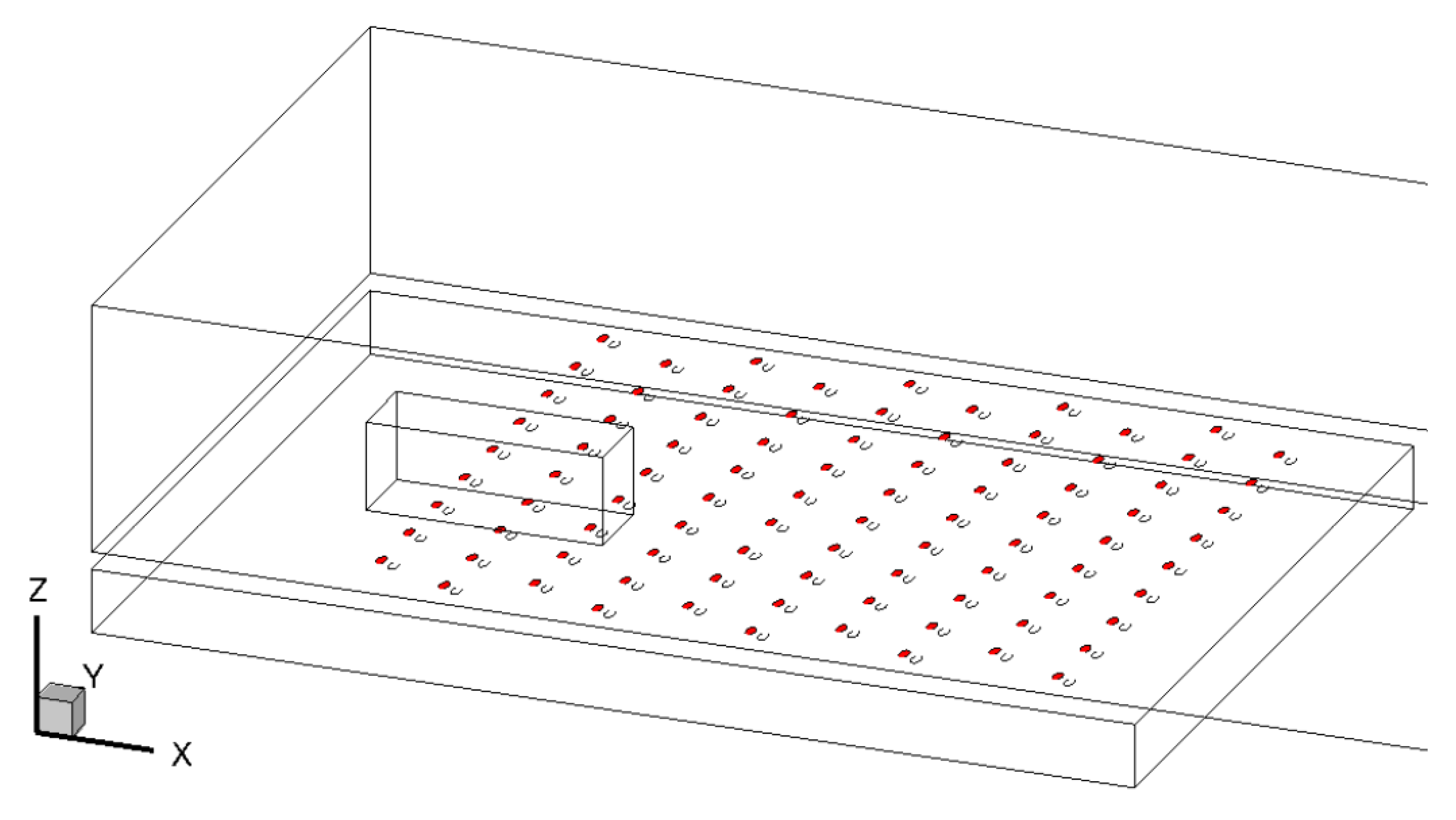
The experimental set-up and the orientation axis conventions are described in Figure 1. The rig is derived from the one used by Michel in a previous study [7], to account for different temperature levels for the primary and secondary flows. Two channels are separated by a multiperforated plate, 10 m m thick. The plate material is aluminium for flow field measurements and PVC for heat transfer data. Contrary to combustion chambers, the primary flow, located in the upper 448 × 135 m m 2 section channel is the cold flow prescribed to ambient temperature. The hot flow is generated in the bottom 448 × 36 m m 2 section channel. A heating device is located at the inlet to create a moderate temperature gradient of about 20 K between the secondary flow and the primary flow. Both flows are generated through a fan located downstream of the test section.
A honeycomb and insulating material have been integrated in the secondary channel to guarantee a well-controlled inlet condition. A valve located upstream of the secondary channel controls the pressure loss and mass flow rate going through the perforations. The perforated area of the plate is characterized by 10 staggered rows of 9 holes as depicted in Figure 2. The plate thickness is 10 mm, the diameter of each hole is 5 mm, and the respective pitch and yaw angles are 30 and 90 . The axial spacing p between the rows is 43.0 mm, the lateral one s is 40.25 mm.
The target velocity in the primary (i.e., cold) flow V p is 3.4 m · s 1 , corresponding to a Reynolds number R e p based on cold hydraulic diameter (defined as 4 S / P , where S is here the test section area and P its perimeter) of 45 , 500 . For the secondary (i.e., hot) flow, the generated velocity is 2.88 m · s 1 , corresponding to a Reynolds number R e s based on hot hydraulic diameter of 11 , 400 . This leads to an average velocity V j of 26 m · s 1 in the holes, corresponding to a Reynolds number R e j based on hole diameter of 7800. In terms of non-dimensional parameters, this leads to a density ratio D = ρ j ρ p of 0.94 , a velocity ratio V v = V j V p of 7.88 , a blowing ratio M = ρ j V j ρ p V p of 7.39 , and a momentum flux ratio I = ρ j V j 2 ρ p V p 2 of 58.2 . Those values, except for the density ratio, are typical of those encountered in a realistic combustion chamber, characterized by highly penetrating jets (see for instance [15]). All instrumentation for the acquisition of flow conditions (mass flow rate, temperature, pressure) has been calibrated and connected to a dedicated acquisition system.

2.2. Aerodynamic Measurements

Particle image velocimetry is used to measure and evaluate mean and RMS velocity fields. Flow seeding is achieved with DEHS micrometric particles, generated with two TOPAS systems. Those particles are injected at the inlet of both flows. The aerodynamic field is acquired by a LaVision’s PIV 2D-3C (or stereo Particle Image Velocimetry called hereafter SPIV) system in order to obtain all velocity components of the flow. In this way, it is illuminated by a sheet generated with a 2 × 200 mJ Nd:Yag pulsed laser through an optical sheet generator provided by LaVision. PIV images are acquired with two 2351 × 2058 pixels IMAGE PRO XM 512 MB cameras with a sampling frequency of 10 Hz for all measurements. Both cameras are equipped with a 100 mm Zeiss lens mounted on a scheimpflug setting and equipped with a 532 nm bandpass filter (with a 10 nm bandwidth) in order to improve the signal-to-noise ratio. Combined with rhodamine coating laid on the perforated plate, the influence of light reflection is reduced allowing velocity measurements in the vicinity of the wall.
The system is installed around the test-rig on a displacement mechanism in order to perform detailed analysis of the flow along the multiperforated plate according Z and X directions (see Figure 1b for axis conventions). The acquisition of images is made with LaVision’s Davis 9 software, and their processing is performed with the fast GPU-based PIV software FOLKI-SPIV developed by ONERA. It relies on the Lucas-Kanade paradigm of iterative registration of local interrogation windows as described in [16].
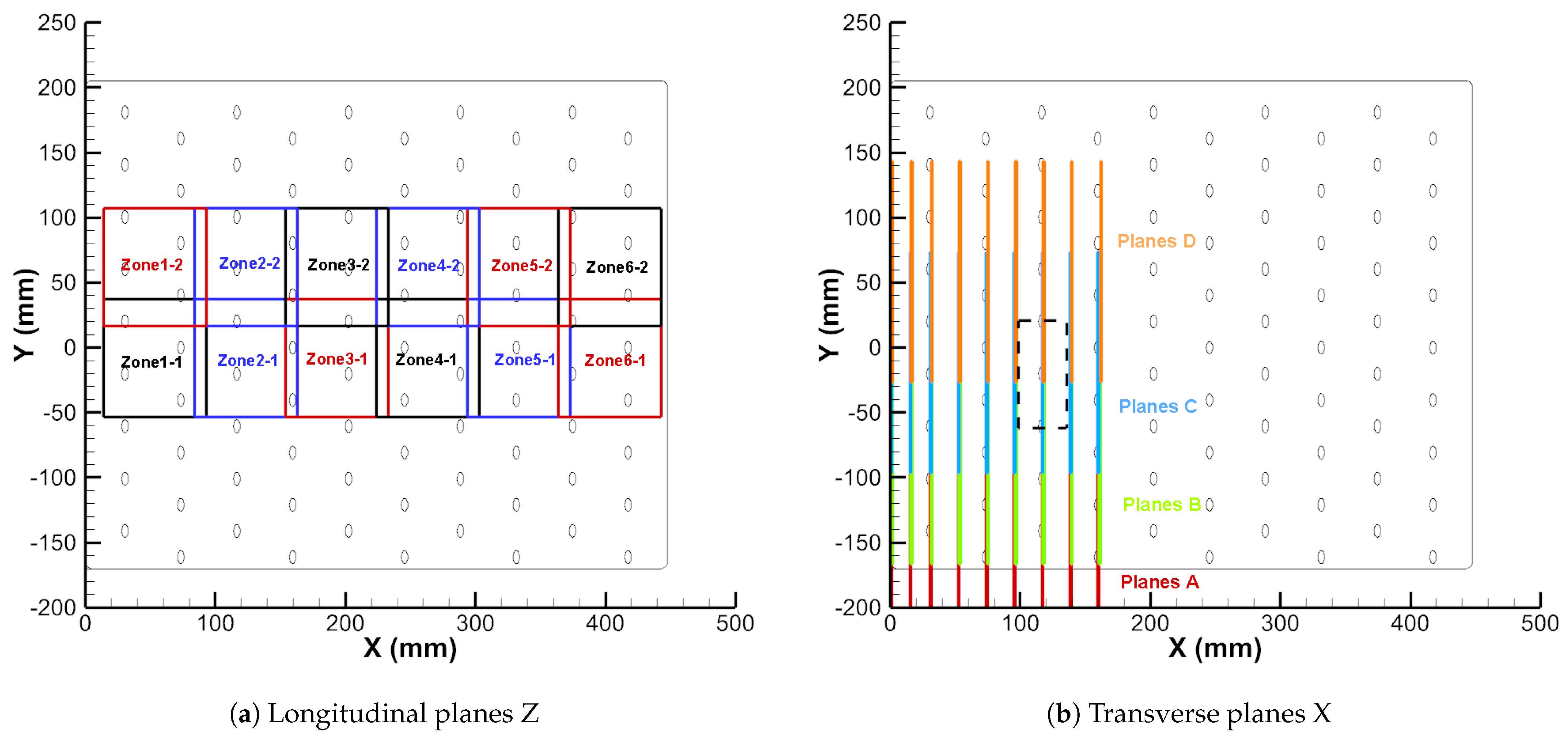
Two SPIV configurations are considered in order to acquire data in both Z-plane (i.e., parallel to the injection plate) and X-plane (i.e., parallel to the main section). In the first one, the half angle between each camera and Z vector is 33 , limiting the reconstruction error of the stereoscopic image as explained in [17]. For each altitude Z, the measurement plane is divided in 12 overlapping 80 × 90 mm 2 windows following the organization depicted in Figure 3a. All velocity components are obtained for 5 longitudinal planes ( Z = 5.8 , 11.8 , 19.8 , 26.8 , 34.8 mm). The pixel size through the global optical system is 38 μ m in the X direction and the size of the reconstructed stereoscopic image is 2351 × 2058 pixels. In the second configuration, each X-plane explored is divided in 4 overlapping 170 × 125 mm 2 windows as illustrated in Figure 3b. Under these conditions, 7 transverses planes, from the 1st to the 4th row with a step of half a row distance, are considered. In this case, the dimension of a pixel through the optical system is 83 μ m in the Y direction and the stereoscopic image is 1700 × 1250 pixels in size. In addition, particular attention was paid to the flow dynamics in the vicinity of a jet coming from a hole of the 3rd row located in Figure 3b by a black rectangle. This area was characterized from 11 planes spaced at Δ X = 1 mm.
For both configurations, 1500 images are acquired for each window. This number of images was shown to be satisfactory to guarantee statistical convergences. The time interval between PIV pulses is about 20 μ s. SPIV images are processed using 13 × 13 pixels interrogation windows, 10 iterations and 3 pyramid levels. In addition, a self-calibration is systematically applied in order to reduce the error induced by a possible gap between the laser sheet and the calibration plate. FOLKI-SPIV provides a dense vector field, with one velocity vector per pixel, yet its spatial resolution is limited by the size of the interrogation window as in others PIV methods. The effective spatial resolution of PIV measurements is then of 0.5 mm and 1 mm, respectively.

2.3. Thermal Measurements

2.3.1. Flow Temperature Measurements

The flow temperature is acquired by a DANTEC cold-wire thermometry system based on a 55 P 15 5 μ m tungsten probe (shown in Figure 4a,b) connected to a 90 C 20 C C A module. Several planes are explored along the first rows of holes. The probe position is prescribed with a displacement system using 1 μ m vertical steps, installed above the test section (Figure 4c).
The measurement box shown in Figure 5 was defined in a zone where the effects of the test section lateral walls are low, based on PIV results:
1.5 mm X 131.5 mm 81.3 mm Y 37.0 mm 0.0 mm Z 50.0 mm
The accurate position of the probe compared to a reference hole is defined using a small yellow plastic object with a small cylinder plugged inside the reference hole (see Figure 4b). The object is made of a small cube (5 mm side) placed on a parallelepiped so that one edge of the cube is exactly at the center of the hole.

2.3.2. Characterization of the Wall Heat Transfer

In the recent years, Pressure Sensitive Paint (PSP) has become an increasingly popular technique for the determination of the adiabatic effectiveness η a w map, as detailed in [18]. However, here, both adiabatic effectiveness and heat transfer coefficient (hereafter HTC or h) maps are required, so it was decided to rely on infrared thermography (IRTh) to derive those maps. The main drawback of IRTh consists in conductive effects inside the wall. However, the conductive model used in post-processing takes them into account as detailed later. The surface heat transfer coefficient and adiabatic effectiveness are derived based on the acquisition of surface temperature distribution. To limit heat diffusion, a PVC multiperforated plate is used for thermal measurements. The extra heating required to generate a significant heat transfer through the plate is provided by an electrical conductive paint from RESCOLL [19] applied on the cool surface (see Figure 6).
The acquisition of wall surface temperature is performed on both sides of the plate, through a vertical displacement of the IR camera, and the use of two mirrors located at positions 1 and 2 in Figure 7a. Both optical paths of the IR camera are illustrated in Figure 7b.
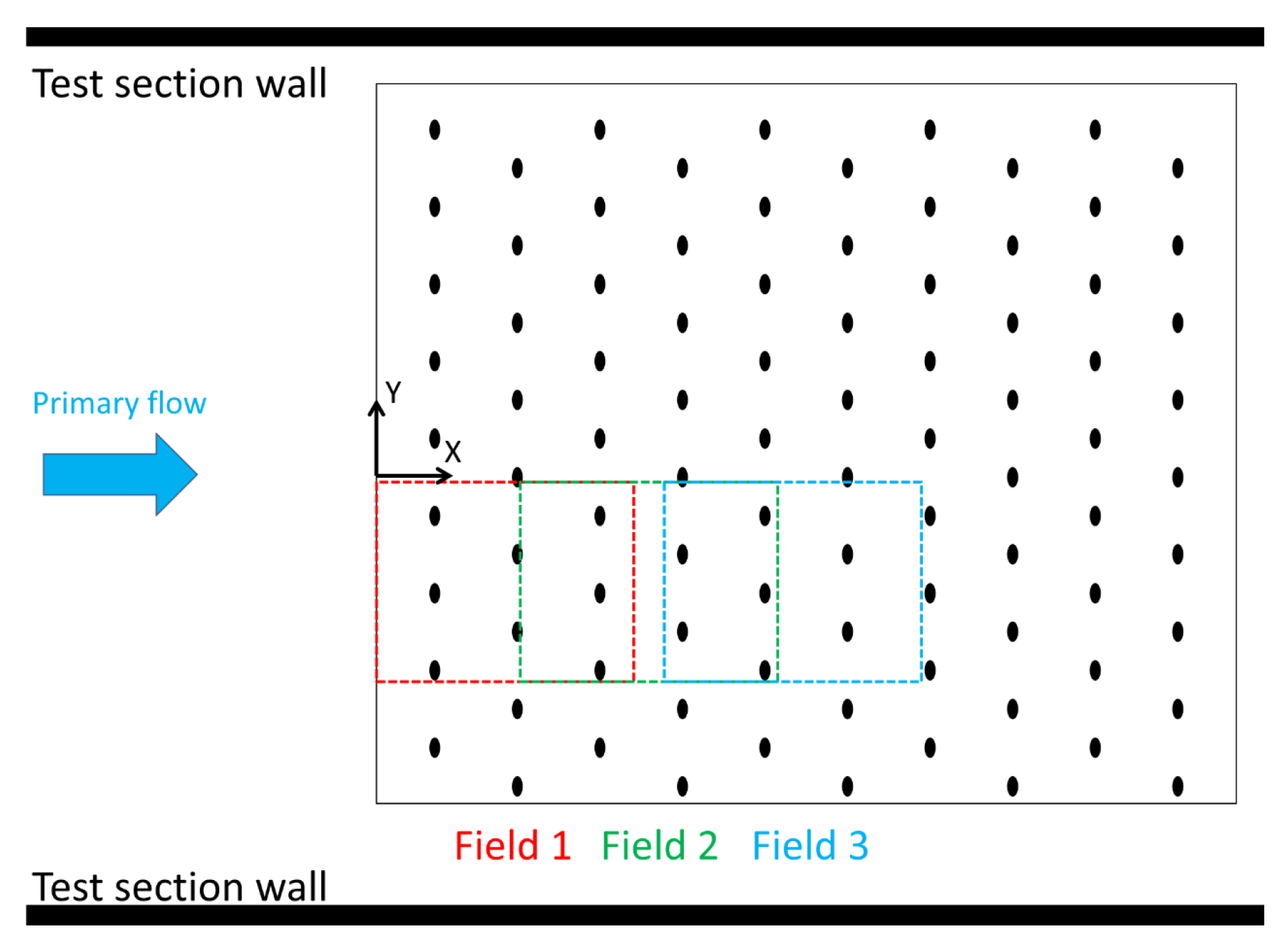
The IR camera is a FLIR SC7600 MWIR with a 50 mm objective. The layout is designed to obtain the same camera-to-wall distance at the two positions: 650 mm. In this configuration, the measurement field on the plate is 117 × 93 mm 2 . To cover a larger part of the multiperforated plate, three measurement fields are needed, by a displacement along X direction with a step of 75 mm as depicted in Figure 8.
For each measurement field, four heating power levels are tested (upper-script ( i ) in Equation (4)). The average surface electrical heat flux generated in these four conditions is the following: ϕ e l ¯ = 0.159313463 W·m 2 . For each heating level, the surface temperature is measured in steady state conditions, on both sides of the plate. A conductive calculation is then performed on the measurement zone of the plate. As the only missing boundary condition is the heat transfer in the holes, it is taken into account considering a model proposed by [20] to estimate the heat transfer coefficient in the holes h h . This numerical thermal model provides the conductive heat flux density ϕ w ( i ) on both sides of the plate. The convective heat flux density is defined by the thermal balance at the fluid/solid interface. On the top side of the plate, it includes the local electrical heat flux generated by the heating paint:
ϕ c v ( t o p ) = ϕ w ( t o p ) + ϕ e l
On the other side, there is no additional heat flux source so:
ϕ c v ( b o t t o m ) = ϕ w ( b o t t o m )
The convective heat transfer coefficient and adiabatic wall temperature are then evaluated through a linear regression of the convective wall heat flux versus wall temperature on both sides:
ϕ c v ( i ) = h ( T w ( i ) T r e f ) , i = 1 . . . 4
This methodology was already presented in [21] for the determination of the heat transfer coefficient.
The local heating power generated inside the paint coating in Equation (2) is a necessary input of the heat transfer balance used to derive the heat transfer coefficient. As the surface heat flux generated by this conductive paint is not uniform because of the presence of the holes, a preliminary experiment is required to identify this non-uniformity. The global electrical power is controlled by measuring total voltage U e l and current I e l , which gives access to the average heat flux density:
ϕ e l ¯ = P e l / S = U e l I e l / S
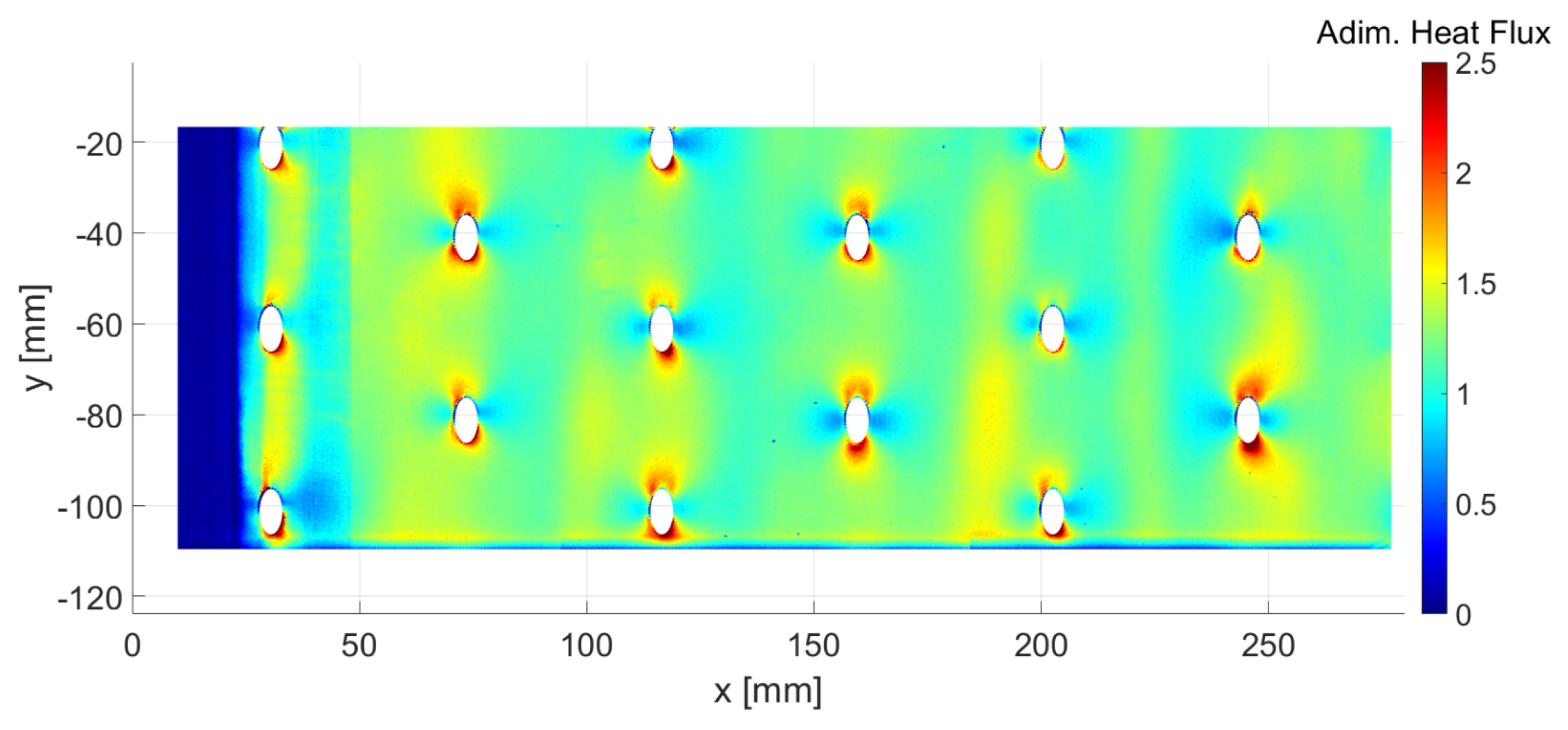
where S is the total heated area. To identify the surface local heat flux, a transient experiment is done under natural convection conditions, without any flow in the primary and secondary channels. The plate top surface temperature is acquired by infrared thermography (position 1 in Figure 7) during the transient heating of the plate. The acquired transient temperature is specified as a boundary condition in a transient thermal model of the plate to calculate the heat flux on its top surface. These experiments and post-processing are carried out for each electrical power level, at the three measurement fields. An example of surface heat flux distribution is presented in Figure 9 by combining the three measurement fields. The surface heat flux is divided by the average electrical power ϕ e l ¯ . Please note that the results obtained for each power level are comparable, with a higher spatial noise at lower levels. The surface heat flux is not perfectly periodic because the paint thickness is not uniform as the painting process is handmade.
As explained above, the local wall HTC and adiabatic temperature are obtained by a linear regression. This post-processing is illustrated in Figure 10. The three graphs show for each measurement field the averaged wall heat flux versus the averaged wall temperature for four different heating levels. The dashed lines are the identified linear fit of these 4 points. The HTC is the opposite of the slope and the adiabatic temperature is the y-intercept.
The uncertainty of the global methodology to identify HTC and T r e f is evaluated based on the uncertainties of all the input parameters: temperature measurements by IRTh and PVC plate thermal properties. These properties are used in the two thermal models: unsteady model for the identification of the heat flux generated by the paint ϕ e l and steady model for the calculation of the wall heat flux under flow conditions ϕ w ( i ) . Considering IRTh, the supplier specifies an uncertainty on temperature of ± 1 K in the measurement range [0; 100 C]. In addition, the uncertainty on wall emissivity, IR windows transmission and IR mirrors reflectivity generates a 3 % uncertainty on temperature. The thermal properties of PVC are based on several sources (see [22] for example): ρ = 1380 kg · m 3 , λ = 0.2 W · m 1 · K 1 and C P = 1046 J · kg 1 · K 1 . Typical uncertainty on thermal properties ( λ and C P ) is 5 % . Taking into account those elements, the uncertainty on HTC and adiabatic effectiveness η a w are given in Table 1.

3. Numerical Model

The mesh was generated using Centaur meshing software [23]. This mesh is hybrid, made of prisms at the walls, tetrahedra far from the wall and a minor number of pyramids. Three successive grids were used to check mesh convergence issues. The first one corresponds to approximately 50 M cells, the second one is about 67 M and the last one 90 M cells. The main difference relies in the mesh discretization inside the holes. For the coarse mesh, around 15 cells are present along one diameter, compared to 30 cells for the fine mesh. The difference on wall temperature between the intermediate and fine meshes not exceeding locally 2%, the intermediate 67 M cell mesh was conserved. The prism size at the wall was adjusted to guarantee a y + , close or less than 1, for the majority of the flow, leading to a cell size of 15 microns near the walls. The y + distributions obtained on both sides of the plate are represented in Figure 11a.
The simulation is completed using ONERA’s in-house CEDRE software. The software is a general purpose unstructured solver, dedicated to applications in the field of energetics and propulsion. A description of the code is provided in [24]. The k- ω SST model was considered as the reference RANS model, being largely used in the industry. Details about this model can be found in [25]. In parallel to k- ω SST model, the ability of Reynolds Stress Models to improve the description of those complex 3D flows is evaluated using Manceau Elliptic Blending Reynolds Stress Model (EBRSM) [26]. This model is more suited for flows dominated by strong curvature and non-equilibrium effects. The elliptic blending allows combining a specific near-wall model with a classical SSG approach far from the wall. Concerning the heat flux modelling, a constant turbulent Prandtl number of 0.85 was used in combination with the k- ω SST model for Reynolds stresses:
u i T ¯ = ν t P r t T x i
This value is a standard value, in particular appropriate for equilibrium boundary layers (see for instance [27]). Regarding the more complex EBRSM calculation, the Daly-Harlow Generalized Gradient Hypothesis was adopted for the turbulent heat flux [28]:
u i T ¯ = C θ u i u j ¯ k ε T x j
A realistic evaluation of the Reynolds Stress tensor is a prerequisite for such a model. Those values are issued from the EBSRM model. The classical value of 0.3 for C θ is used here.
The boundary conditions (see Figure 11b) were estimated from the averaged experimental values of pressure or mass flow rates. Subsonic inlets are prescribed for the hot and cold channels. For the main flow, a surface mass flow rate of 3.97 kg · m 2 · s 1 and a total temperature of 293.75 K are specified. For the hot flow, the mass flow rate and temperature are respectively equal to 3.20 kg · m 2 · s 1 and 317.35 K. For the k- ω SST model, for both channels k and ω are taken respectively as 0.1 m 2 · s 2 and 100 s 1 . For the EBRSM model, u u ¯ , v v ¯ and w w ¯ are taken to 0.066 m 2 · s 2 , ε and α respectively to 1 m 2 · s 3 and 1. The outlet static pressure was taken equal to 100,245 Pa. No-slip conditions are prescribed for all walls. The comparison between the experimental results and the SST simulation was already presented in [29]. Therefore, in the next sections, all presented results will correspond to the EBRSM modelling. Those results show a clear improvement, in particular for heat transfer, as will be shown in Section 4.2.2.
Coming to the thermal modelling, two calculations were performed. For the first simulation, the plate was considered to be adiabatic to obtain T a w . For the second one, a temperature of T w = 319.35 K is prescribed, corresponding to a temperature level guaranteeing a positive wall heat flux ϕ w everywhere. The heat transfer coefficient is then derived, writing:
ϕ w = h ( T w T a w )
The calculations carried out here are limited to the fluid domain. A conjugate model would have been more representative of the real set-up. However, the PVC character of the plate for thermal measurements limits the conductive phenomena. Moreover, Bizzari et al. [15] compared a conjugate and an adiabatic model, showing that, except in the very near-wall region, the velocity and temperature profiles are identical. Lastly, the fluid model is already large, and the additional cost of a solid model was judged too high, regarding the elements stated before.

4. Discussion

4.1. Dynamics of the Flow

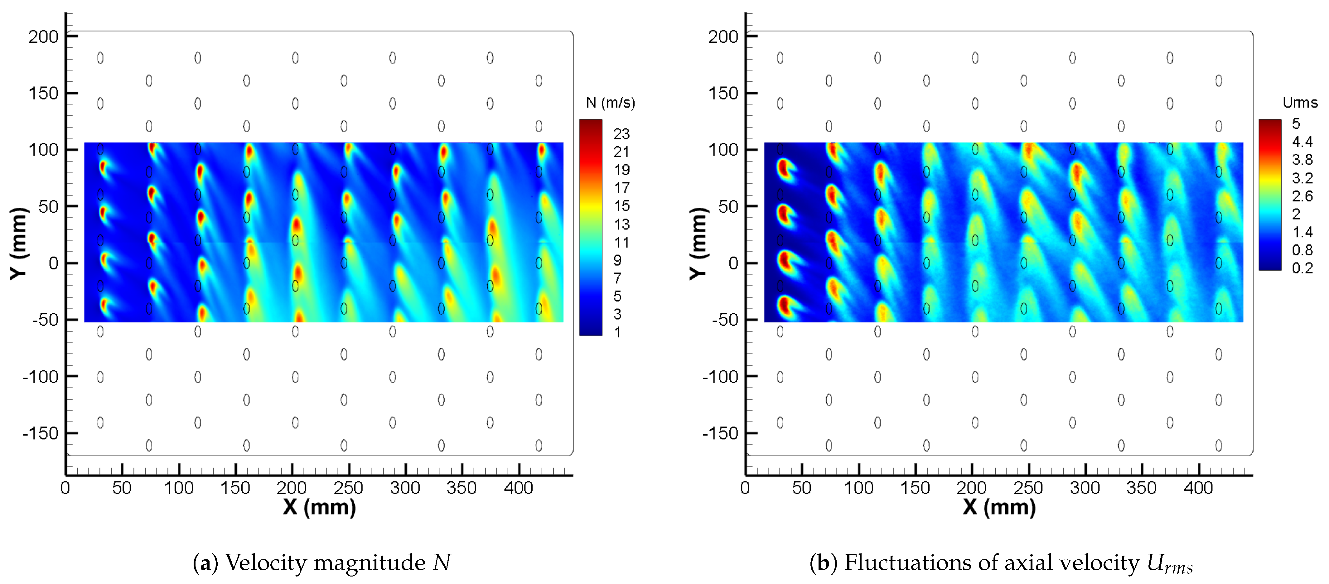
The whole measurement area is presented in the plate frame in Figure 12, which shows the maps of velocity magnitude N and the fluctuation of axial velocity U r m s (i.e., the root mean square level of measured velocities), both measured 5.8 mm above the injection plate. The axial velocity upstream of the multi-perforated plate is between 3.4 and 3.9 m · s 1 , the flow being already affected by the presence of the jets. As a reminder, the theoretical primary flow velocity is 3.4 m · s 1 as considered in Section 2.1. In the associated Figure 12a, the peak velocities correspond to the intersection of hot jets with the measurement plane. The maximum velocities are observed in the holes and at the hole exit, with local values of 30 m · s 1 , to be compared with the free stream velocity. It appears that the cartography is strongly heterogeneous and does not exhibit any periodic behavior. The three first rows present a common pattern, from one hole to another. At this location, each jet pattern is highlighted by two high velocity branches which are linked to the trace of the counter-rotating vortices classically generated by the interaction between the crossflow and the jet (as illustrated in Figure 12a). High velocity fluctuations are localized in the vicinity of the holes and outlined small discrepancies in jet wakes directions as shown in Figure 12b.
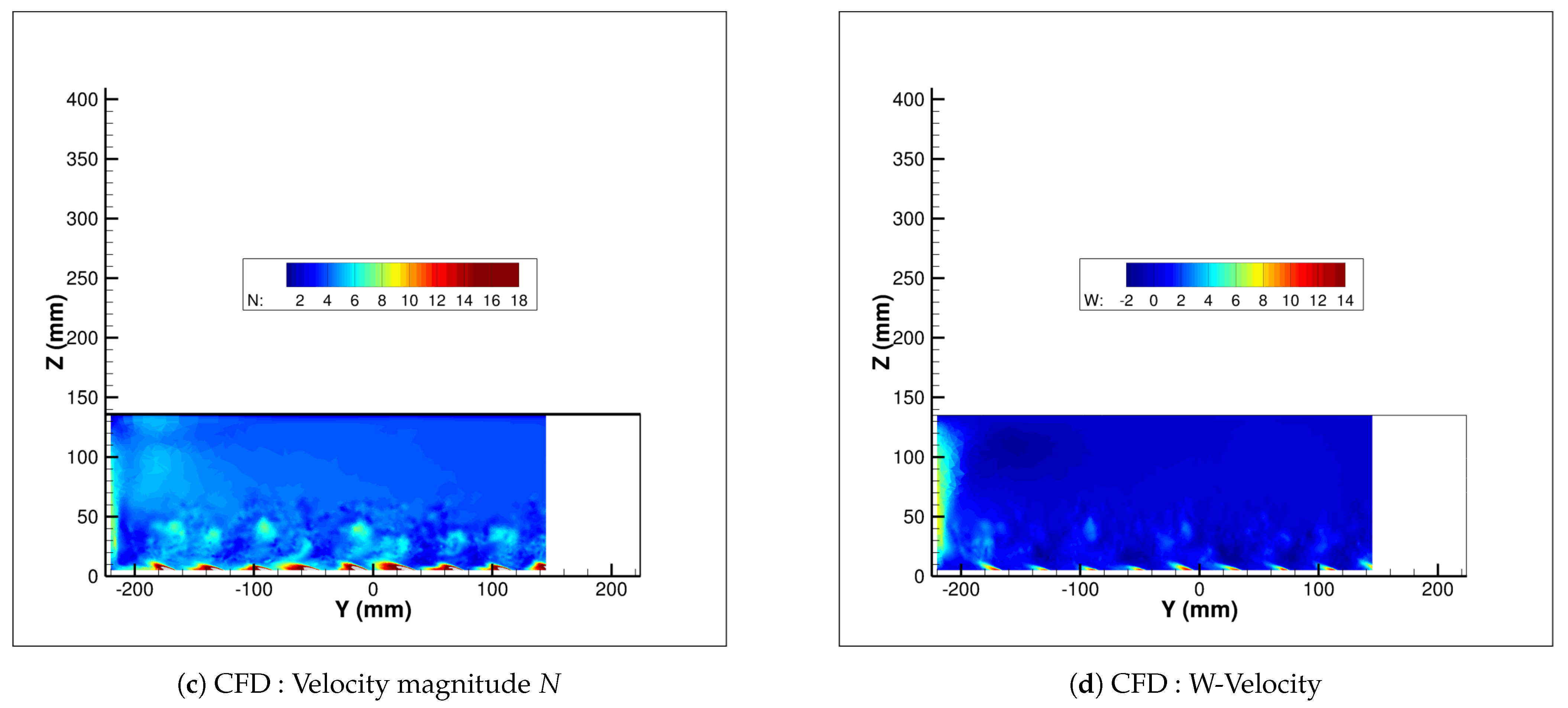
Nevertheless, in 2nd and 3rd rows, the process appears to be more diffusive, with an extended high velocity zone. This behavior is directly driven by the interaction of the jets with the film created by the preceding rows, compared to the undisturbed inlet main-flow seen by the first row. Similarly, as shown in Figure 13a,b which depict the experimental maps of the velocity magnitude N and vertical velocity W respectively, the location of the jets coming from the first row is quite visible as mushroom or kidney shapes above the new row of jets (see Figure 13a). Due to the presence of the left sidewall, the jet at the left end appears much more developed than the other jets in the row. The vertical velocity field clearly shows the development of a recirculating flow induced by the impact of the flow on the sidewall (see Figure 13b). Figure 13c,d show the same fields, obtained in the EBRSM simulation. The footprint of the jets issued from the first rows are less organized, with no clear periodicity of the flow. The jets of the 2nd row are less penetrating, and they are more deviated close to the wall. The vertical velocity map exhibits the same high velocity near the lateral wall corresponding to a circulation of the flow along this wall.
To define a close-up of jet behavior, a reconstructed 3D field of the velocity magnitude is performed with the combination of several SPIV measurements focused on the 3rd row of holes (see Figure 3b for the exact location of the measurement). The dual figures presented in Figure 14 show the jets in interaction with the main flow. In particular, in Figure 14a, one can observe the traces of the previous row flowing above the observed jets.
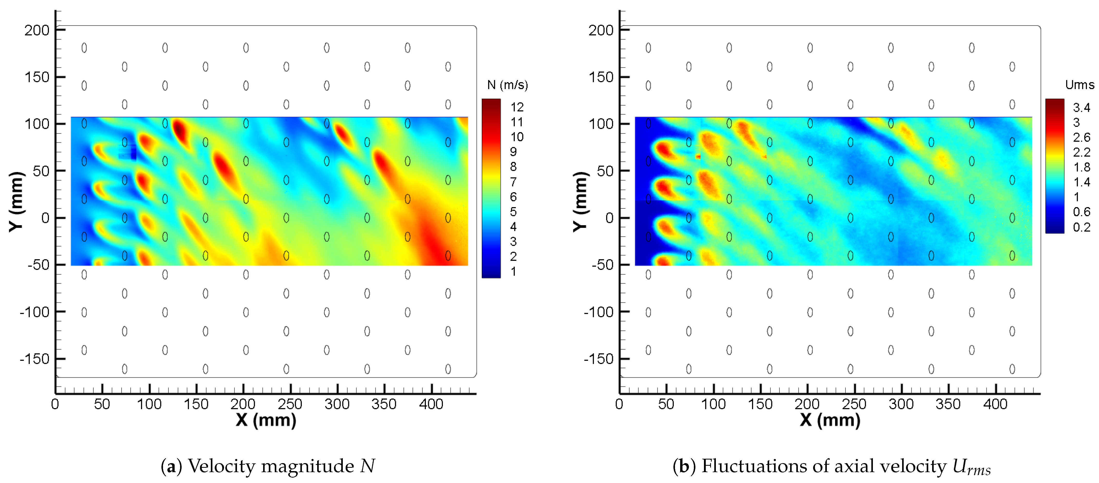
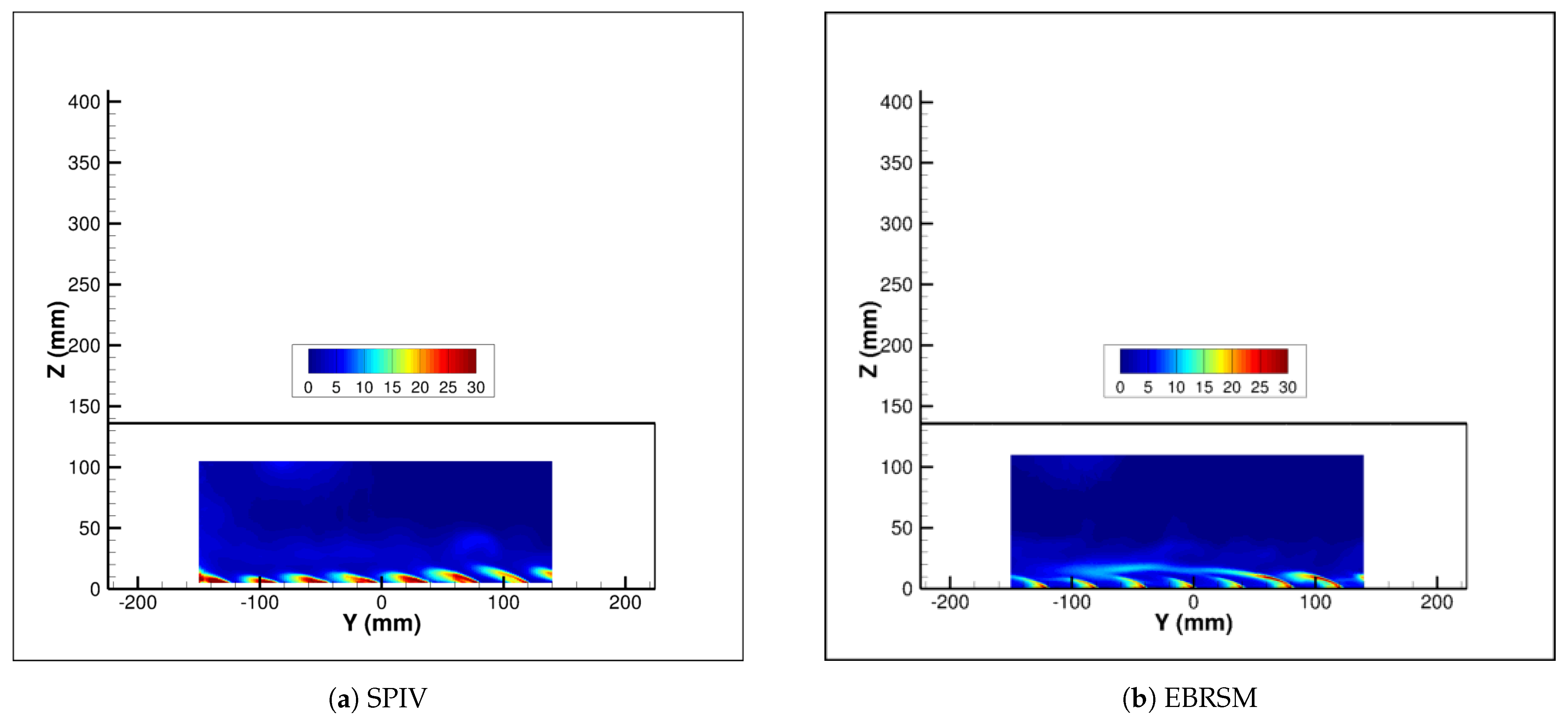
When the distance to the wall is increased (i.e., in Z direction), one can follow the organization of all jet flow interactions as illustrated in Figure 15. Here, the direction of the different jets marked by their own wakes is different depending on the emission row considered. In particular, the jets generated from the fifth row near position X = 200 mm take a direction perpendicular to the main flow. This behavior reveals a loss of flow entrainment for those latter. In following altitudes, as for instance in Figure 16, the complex topology of the interaction between the grid of jets and the transverse main flow shows that, starting from the 4th row of holes upstream, the direction of the flow is globally disturbed by a phenomenon other than the injection of the jets alone. Indeed, as no periodic regime is established for the next rows, the behavior observed after the 3rd row is even more chaotic, with a less clear penetration of the jets for rows 4 and 5. In fact, a massive lateral movement is generated in the main channel, created by the entrainment of air by the hot jets, which interacts very rapidly with the left hand test section wall producing a recirculating flow towards the center of the plate. This behavior is clearly confirmed by Figure 17 where the velocity fields show a modification of the expected film cooling flow, with a lateral perturbation amplifying and taking up more and more space. This lateral back flow is located in the left half of the test section and is characterized by high velocities similar to the velocity of the main flow.
As a matter of fact, when the flow impinges on the lateral wall, it is deviated towards the upper wall, which creates a strong vortex in the channel, and prevents the flow from being periodic. In the end, the whole film cooling flow is affected by this boundary effect induced by the present flat model configuration. Even if this flow differs from the one encountered in combustion chambers, which are often tubular, most regions offer a clear view of the interaction between the jets and mainstream, for a 90 side injection, in particular for the first rows. The comparison between experimental and computational results reveals the same flow topology.
Figure 18 details the comparison between measured and simulated velocity magnitudes at the 1st, and between the 1st and 2nd rows. The agreement for the first row is satisfactory, though the calculation underestimates the velocity in between the holes. The entrainment provided by jet injection is higher in the measurements, even with the use of an EBRSM model. This trend is still observed between the two first rows. The footprint of the vortices created at injection is more pronounced and less diffused in the simulation compared to PIV values, despite the Daly-Harlow model used in the EBRSM for turbulent stresses.
This turbulent diffusion process is directly illustrated by the turbulent fluctuations map. Figure 19 shows the comparison of the measured vs computed turbulent kinetic energy k maps at the 4th row. It appears that the maximum level of k is correctly predicted by the EBRSM model. However, the extension of the region where the turbulent kinetic energy is high is largely underestimated by the Reynolds Stress model. The lateral extension of temperature being based on turbulent diffusion, one can expect a poor quantitative prediction of the mixing between the hot jet and the cold primary flow in this region. Another key difference is the lack of clear periodicity of the flow predicted by the EBRSM model, as opposed to the SPIV map (see Figure 19).

4.2. Heat Transfer Characterization

4.2.1. Primary Flow Temperature

One of the main contributions of this study is the thermal characterization of the flow field around the holes. This is of particular interest for code validation.
Eight planes are investigated:
  • 6 constant-X planes: X = 1.5 (inlet conditions, 32 mm upstream 1st row), X = 30.5 (1st row), X = 52.0 , X = 73.5 (2nd row), X = 95.0 , X = 116.5 (3rd row)
  • 1 constant-Y plane: Y = 61.15 at the center of one hole in 1st and 3rd rows
  • 1 constant-Z plane: Z = 5 above the center of one hole in 3rd row
The measured temperature is non-dimensionalized by the following relationship:
T a d = T f l u i d T c o l d T h o t T c o l d
The uncertainty of cold-wire temperature measurement is ± 0.5 K. Considering the uncertainty on inlet fluid temperatures, the uncertainty on the non-dimensional temperature T a d is ± 0.03 .
The six constant-X planes are plotted in Figure 20, which allows determining the 3D thermal footprint of this configuration. The inlet plane ( X = 1.5 mm) reveals the warm-up of the boundary layer generated by the heat flux through the separation plate. This is a confirmation that the configuration cannot be considered to be a perfectly adiabatic one. The second transversal plane above the first row exhibits a hot spot corresponding to a jet injection location. The 90 yaw angle of the jets generates a major misalignment between the primary flow and the jet. This results in a relatively cold temperature immediately downstream the first hole. However, going through the various transversal planes, the temperature gradually increases, which corresponds to the creation and consolidation of a more and more efficient insulating film.
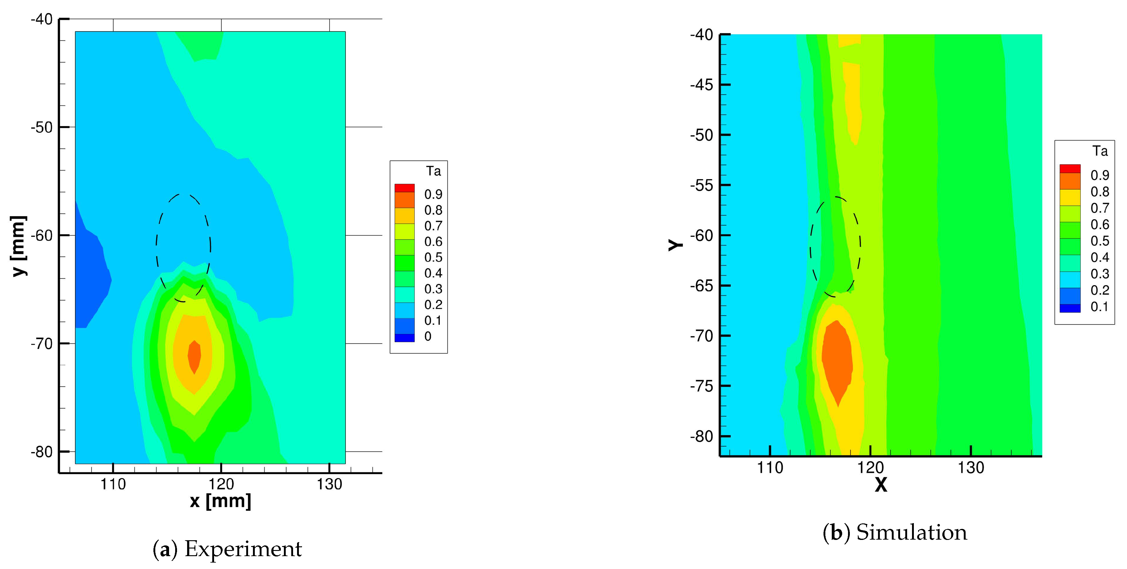
The temperature in a plane parallel to the wall, centered above one hole of the 3rd row is shown in Figure 21. The ellipse drawn in dashed line shows the location of the hole on the wall. The maximum temperature is shifted of about 10 mm (along Y) from the center of the hole due to the 30 injection angle. The deviation due to the main flow is small ( + 1 mm along X) because of the high blowing ratio. As the plane is 5 mm above the wall, the hot jet non-dimensional temperature is decreased down to 0.83 due to the mixing with the main flow. The EBRSM simulation exhibits a fairly good agreement, with a more pronounced peak and a less diffused temperature field.
The constant-Y plane at the center of the measurement box is shown in Figure 22. The three small rectangles in dashed line represent the three injection holes positions. Only the first and third rows are in the measurement plane. The temperature map clearly shows a maximum equal to 1 located at these two injection points, as the jets cross the measurement plane. At the second row the trace of the jet coming from the hole at Y = 41.0 mm is visible about 10 mm above the wall, with a reduced maximum ( 0.53 ) due to mixing of the hot jet with the main cold flow. The trace of the jet coming from the hole at Y = 20.9 mm of the first row is also visible around X = 60 mm and Z = 25 mm with T a d = 0.3 . The EBRSM simulation exhibits a somewhat different mixing process. Even if the injection points are clearly present, the magnitude of the vortices injected at Y = 41.0 mm is higher, with a less diffused pattern. In the simulation, the near wall zone is dominated by rather medium temperatures, contrary to measured ones, which are closer to the cold temperature.

4.2.2. Wall Heat Transfer

Wall Temperature Distribution

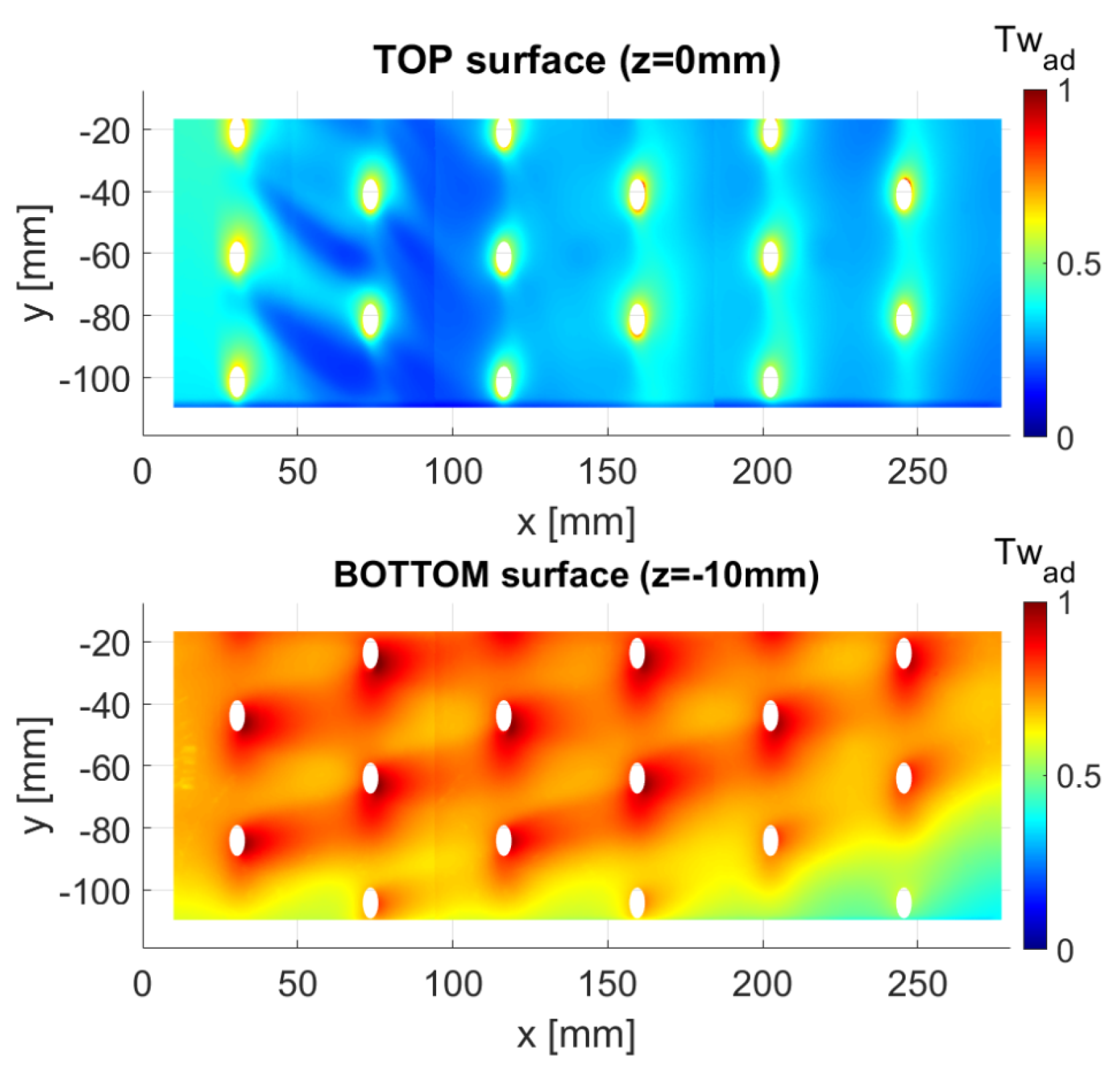
The wall temperature on both sides of the multiperforated plate in steady state conditions with no electrical heating is shown in Figure 23. The measured wall temperature is non-dimensionalized by the following relationship:
T w a d = T w T c o l d T h o t T c o l d
It is important to remember that these temperature maps are not exactly the adiabatic temperature because of the heat conduction inside the plate. However, their analysis allows describing the global heat transfer on both sides of the separation plate. The temperature map on the top surface (cold side) shows hot spots around each hole, because of heat conduction inside the plate due to the heat exchange between the hot flow coming through the holes and the wall. A colder zone appears between row 1 and row 3 where the cold primary flow is driven to the wall because of the recirculation generated by the jet injections. On the lower surface (hot side) the temperature is close to the inlet secondary flow temperature with hot spots downstream of each hole.

Wall Heat Transfer Coefficient and Adiabatic Wall Temperature

The process for the identification of HTC and reference temperature is detailed in Section 2.3.2. In the same paragraph the uncertainties are also evaluated. Figure 24a presents maps of HTC and non-dimensional reference temperature for both sides of the plate. The non-dimensional reference temperature, corresponding to the adiabatic effectiveness is defined as:
η a w = T r e f a d = T r e f T c o l d T h o t T c o l d
Please note that the zone upstream the first row of holes ( X < 25 mm) must not be considered because of the presence of a copper bar providing electrical power to the conductive paint. In this region, the wall heating is not efficient and the wall model is not accurate because it does not take into account the copper bar.
The HTC distribution on the injection side is driven by the near-wall velocity distribution (as seen in Figure 12). The HTC distribution is strongly heterogeneous downstream the first row, with large discrepancies between regions of high velocity fluid and low velocity fluid. The maximum HTC areas are located in the injection region and can reach 150 W · m 2 · K 1 . In the inter-row region, the HTC varies from 40 to 90 W · m 2 · K 1 . The HTC distribution after the third row differs from the preceding rows, with no clear trace of the jet mixing with the main flow. The same pattern was found for near wall velocity and is explained by the 3D character of the flow, with a major lateral movement of the fluid across the primary channel. The non-dimensional reference temperature exhibits the same qualitative behavior, driven by the mixing between the hot jets and cold flow.
On the bottom surface, the distribution of HTC is more homogeneous between the holes. Downstream of each hole, a major heat transfer enhancement is present. As put in evidence by Byerley [30], this enhancement is due to the suction of the boundary layer by the hole, and to a local impingement of the flow downstream of the hole. The analysis of the non-dimensional bottom reference temperature reveals a relatively homogeneous value, close to 1 i.e., the reference temperature is close to the hot temperature. The values identified are generally a little lower than 1 because a thermal boundary layer develops on each side of the separation plate before the first row so the secondary flow temperature decreases near the wall.
The numerical results presented in Figure 24b,c can be compared to experimental ones. The agreement appears to be qualitatively satisfactory. However, quantitatively, major differences emerge. Considering the adiabatic temperature map, it is generally overestimated by the calculation, which corresponds to a warmer than measured temperature. The average difference appears to be between 20–30%. In the simulation, in the first three rows, the simulation exhibits a clear trace of the jets at hole exits. In the experiment, in the same region, the adiabatic temperature is really low, corresponding to a migration of the external cold flow near the wall. The low values observed for the HTC in the calculation downstream of the 3rd row appear in the experiment after the 4th row, with higher values. In other terms, the low velocity zone beyond this row seems to be underestimated by the calculation. The origin of such a zone being the roll-up of the primary flow with the jets, it appears to be difficult to predict even with a Reynolds Stress model. The magnitude of the velocity in such a region can be therefore very sensitive to turbulence modelling. Such a discrepancy is not necessarily surprising. For a cold jet in a hot crossflow, classical isotropic models exhibit differences that can be higher. For the current configuration, which is much more complex than an isolated jet in crossflow, higher differences are to be expected. The EBRSM should improve the dynamic field; however, as shown in [31], the heat transfer modelling is in itself a question. Even more sophisticated models such as GGDH or HOGGDH fail to predict heat transfer correctly. That could be an explanation as for why the temperature field is not adequately described in our calculation.
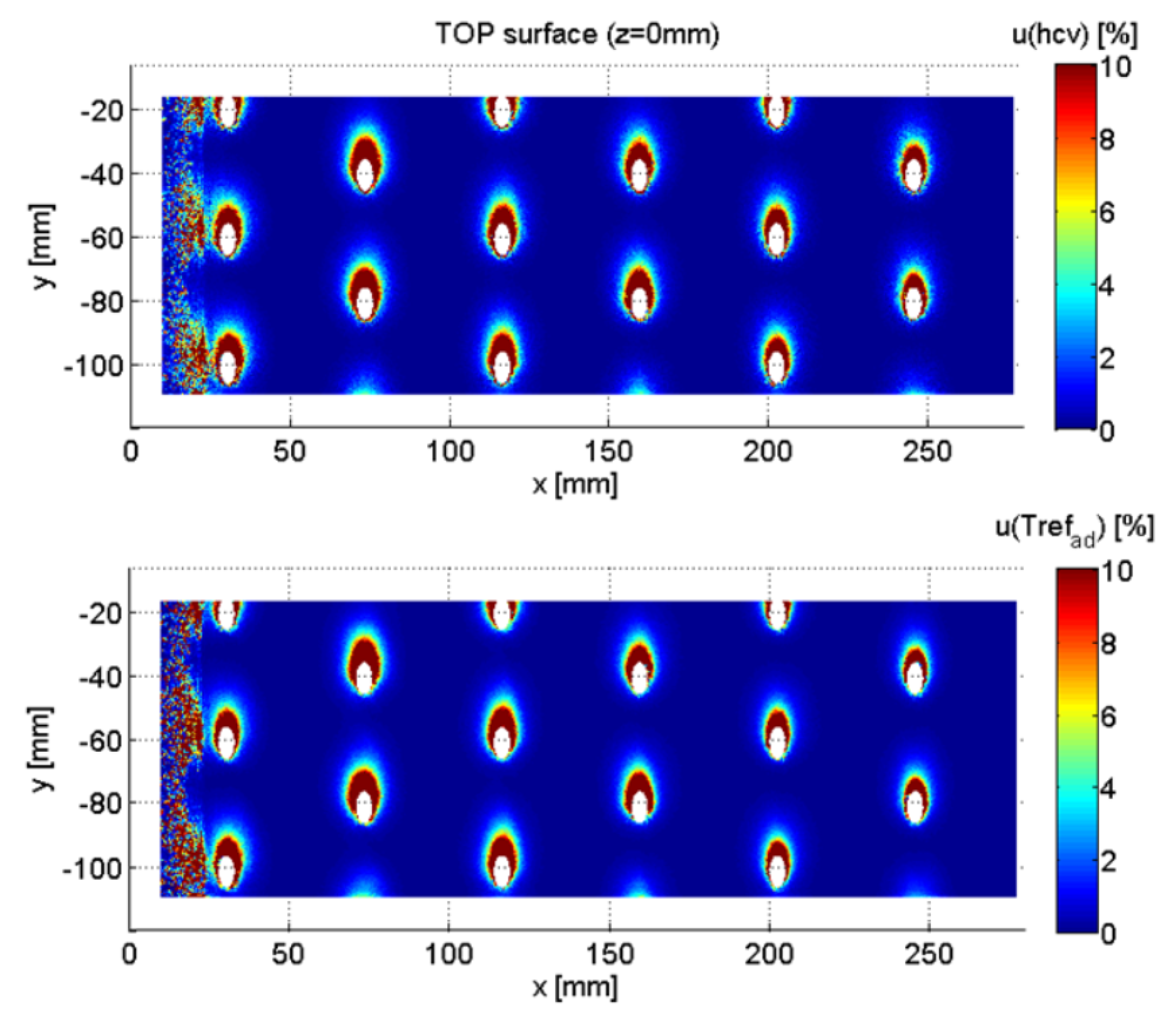
As detailed in Section 2.3.2 the post-processing of the temperature measurements for HTC and adiabatic temperature determination is based on a thermal model of the multiperforated plate. In this model, the HTC inside the holes h h needs to be specified. The results presented above are obtained with a value calculated from CEDRE numerical simulations: h h = 150 W · m 2 · K 1 . Latzko’s correlation (see [20]) provides a higher value: h h = 220 W · m 2 · K 1 . To estimate the sensitivity of our results to this parameter, all the post-processing is done again with this new value. The relative difference with the previous results is drawn in Figure 25, with
u ( h c v ) = h 220 ( x , y ) h 150 ( x , y ) h 150 ( x , y )
u ( T r e f a d ) = T r e f a d 220 T r e f a d 150
The sensitivity is high only near the holes where the surface heat flux calculated by the thermal model highly depends of the HTC inside the holes. In this region, the uncertainty on the surface HTC becomes higher than 10 % . Everywhere else on the surface, the sensitivity is lower than 1 % .
Concerning wall heat transfer, Sen et al. [3], introduced the concept of Net Heat Flux Reduction or NHFR. The NHFR measures the reduction of heat flux, if one compares for the same wall temperature the flux with film cooling ϕ w to the flux without film cooling ϕ w 0 , which reads:
N H F R = 1 ϕ w ϕ w 0
where ϕ w = h ( T w T a w ) and ϕ w 0 = h 0 ( T w T a w 0 ) , note that the temperature differences are inverted to obtain positive heat fluxes.
Sen et al. [3] show that the NHFR provided by the film has two origins, i.e., the diminution of HTC and that of adiabatic wall temperature. The most important effect of the protective film is to create an influence temperature as close as possible to the target temperature (here the hot temperature). However, the modification of the HTC for a film cooling configuration cannot be neglected, on the injection side, but also on the suction side.
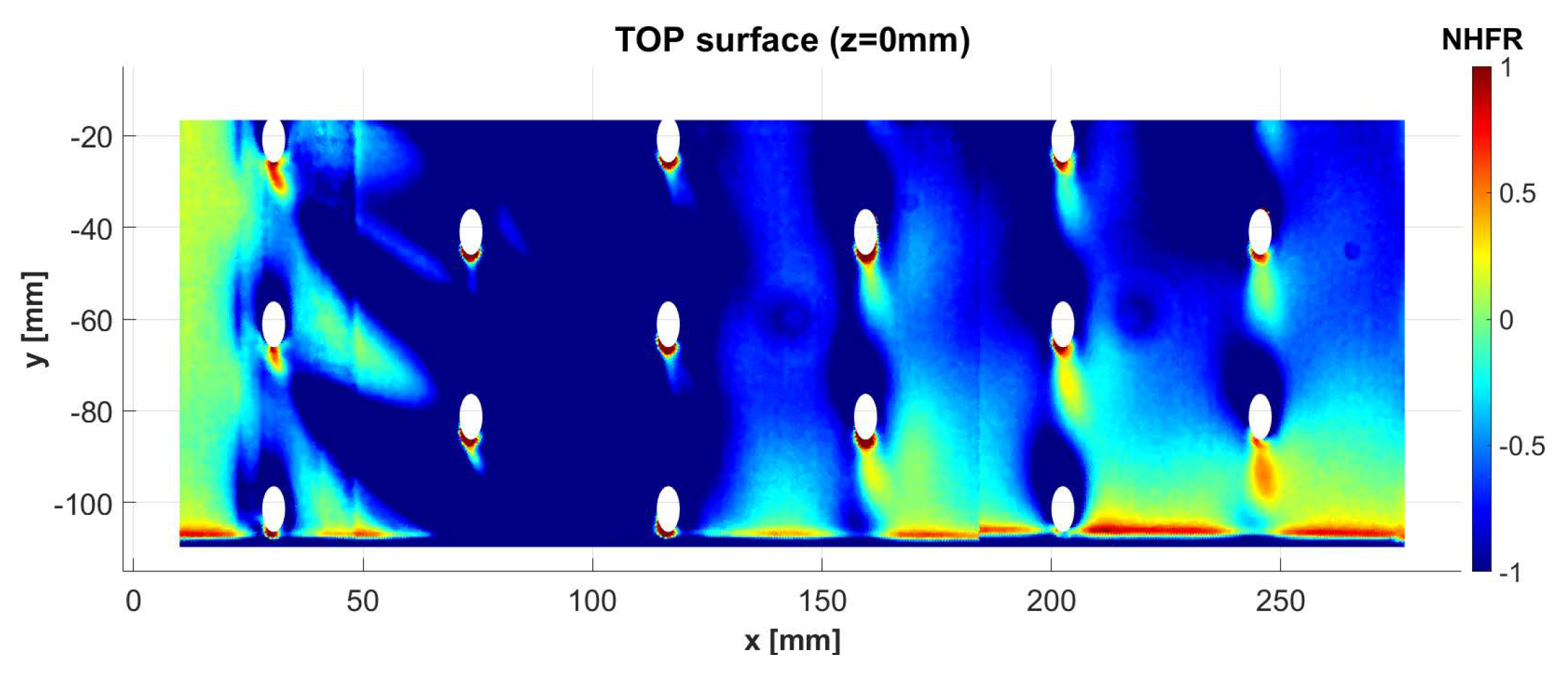
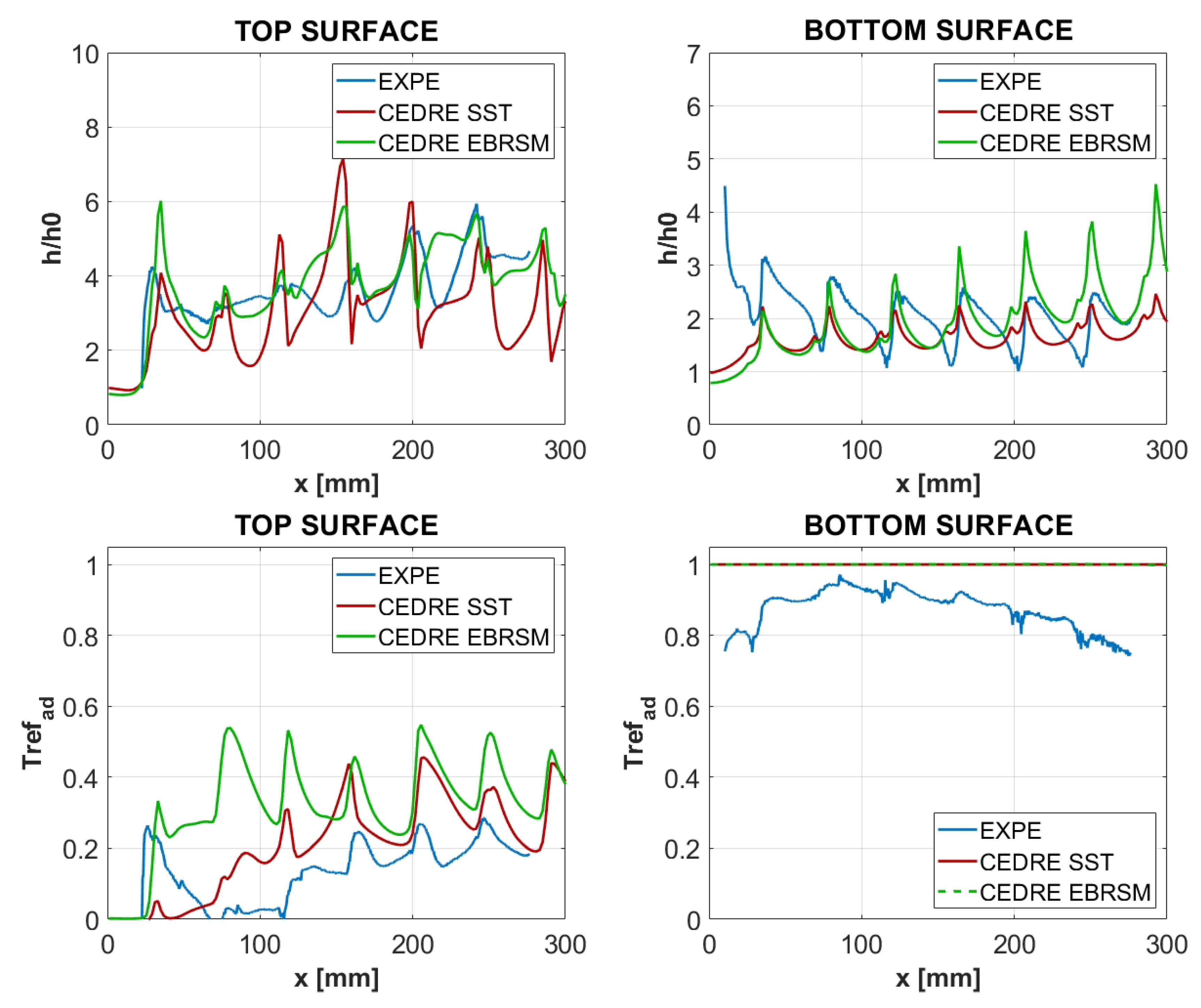
From the results obtained in our experiment, the NHFR is calculated considering a wall temperature equal to the wall temperature measured in steady state conditions (drawn in Figure 23). As for the HTC without film cooling, the following value is provided by the numerical simulation in the zone upstream of the first row of holes: h 0 = 16.7 W · m 2 · K 1 . The adiabatic temperature without film cooling is equal to the primary flow temperature: T a w 0 = T c o l d . The NHFR map (Figure 26) shows mainly negative values. These negative values are due to the combination of low cooling effectiveness and high HTC increase (as seen in Figure 27) because of the high momentum flux ratio of jet injection compared to the one studied by Sen et al. [3]. Under these conditions, the NHFR becomes negative: the wall heat flux with film cooling is larger than the one without film cooling. Only further downstream the fourth row of holes the protective film begins to develop and the NHFR begins to increase but remains mainly negative as the HTC ratio stays higher than 3.
The local measurements presented above are laterally averaged to gain an understanding of the global cooling properties. A filtering treatment is applied in the immediate hole edge region where the obtained values appear to be questionable. Results for the HTC and the adiabatic effectiveness are presented in Figure 27. The HTC distribution is presented in terms of the ratio h / h 0 . The reference h 0 corresponds to the upstream HTC provided by the numerical simulation. The HTC enhancement on the top surface appears to be around 3 or more in this configuration, both for the experiment and the SST/EBRSM simulations. Peaks are more pronounced in the simulation, which can be at least partly attributed to the absence of conjugate effects in the numerical model. On the suction side, the same conclusion appears, with an increase in heat transfer downstream the holes. On the bottom surface, the adiabatic temperature is below 1, corresponding to a cooling of the flow through the PVC plate. On the top surface, the adiabatic temperature is close to the cold temperature between X = 60.0 mm and X = 120.0 mm, everywhere in the spanwise direction. Concerning the comparison between the SST and the EBRSM simulations, the heat transfer coefficient is slightly increased by the EBRSM compared to the SST reference, after X = 100.0 mm. However, the main difference between the two models relies on the adiabatic effectiveness along the first three rows, where the EBRSM largely overestimates the experimental value, and the SST simulation.
Concerning adiabatic effectiveness, the initial protection provided by the film in the first rows therefore appears to be very low. In the first row the adiabatic effectiveness increases, corresponding to the hot fluid injection. Then, the roll-up of cold air around these jets brings this air near the wall, corresponding to a decrease in efficiency. The film only appears to build up after the third row ( X = 116.5 mm), with an effectiveness of 0.2 . This low effectiveness is largely due to the high momentum flux ratio of the experiment. A better coverage is generally obtained on tubular configuration, where the flow is periodic.

5. Conclusions

In the framework of the EU FP7 SOPRANO program, a test rig was developed to study the aerothermal field around a 12:1 scale multiperforated plate, with 90 deg compound angle injection. The non-dimensional blowing ratio considered is representative of the one encountered in aeronautical combustion chambers. The velocity field is documented using SPIV technique. The temperature field is acquired using cold wire technique, whereas Infrared Thermography and an appropriate post-processing allow the estimation of the adiabatic effectiveness and the convective heat transfer coefficient. It is shown that, in the first three rows, the film protection is not efficient. Due to the high blowing ratio, in this region, the convective heat transfer coefficient enhancement is around three, with freestream cold air brought close to the wall by vortices created at injection. After four rows, the film builds up, leading gradually to a better insulation of the wall. The comparison with a numerical simulation conducted with an Elliptic Blending Reynolds Stress turbulence model exhibits a qualitative agreement on the main flow structures. However, the mixing between the jets, the film and the freestream is underestimated by the calculation, even if the results are in better agreement compared to a k- ω SST isotropic model. In the near future, the use of more elaborate anisotropic models for turbulent heat diffusion is expected to improve the temperature field prediction.

Author Contributions

Methodology, E.L., D.D. and P.R.; formal analysis, E.L., D.D. and P.R.; investigation, E.L., D.D. and P.R.; writing—original draft preparation, E.L., D.D. and P.R.; writin-g–review and editing, E.L., D.D. and P.R. All authors have read and agreed to the published version of the manuscript.

Funding

The authors wish to gratefully acknowledge the support of the European Union under the SOPRANO H2020 project award 690724.

Data Availability Statement

The data presented in this study were obtained in the frame of H2020 FP7 SOPRANO project (https://www.soprano-h2020.eu/).

Acknowledgments

The authors want to thank Thomas Batmalle and Adrian Camblor Gomez for their technical support during experiments and data exploitation.

Conflicts of Interest

The authors declare no conflict of interest. The funders had no role in the design of the study; in the collection, analyses, or interpretation of data; in the writing of the manuscript, or in the decision to publish the results.

Abbreviations

The following abbreviations are used in this manuscript:
Acronyms
IRThInfrared Thermography
HTCHeat Transfer Coefficient
NHFRNet Heat Flux Reduction
RANSReynolds Averaged Navier-Stokes
RSMReynolds Stress Model
SPIVStereo Particle Image Velocimetry
Subscripts
a d non-dimensional
a w adiabatic
c o l d primary channel (cold flow)
c v convection
e l electrical
hhole
h o t secondary channel (hot flow)
r e f reference
tturbulent
wwall
Nomenclature
C P specific heat[J·kg 1 · K 1 ]
hheat transfer coefficient[W·m 2 · K 1 ]
kturbulent kinetic energy[m 2 · s 2 ]
Nvelocity magnitude[m·s 1 ]
paxial spacing of hole rows[m]
P r Prandtl number[−]
R e Reynolds number[−]
slateral spacing of hole rows[m]
Ssurface area[m 2 ]
Ttemperature[K]
X , Y , Z spatial coordinates[m]
U , V , W velocity components[m·s 1 ]
U r m s , V r m s , W r m s velocity fluctuation components[m·s 1 ]
Greeks
α pitch angle[ ]
β yaw angle[ ]
η effectiveness[−]
λ thermal conductivity[W·m 1 · K 1 ]
ϕ heat flux density[W·m 2 ]
ρ density[kg·m 3 ]

References

  1. Mayle, R.; Camarata, F. Multihole Cooling Film Effectiveness and Heat Transfer. ASME J. Propul. Power 1975, 97, 534–538. [Google Scholar] [CrossRef]
  2. Schmidt, D.L.; Sen, B.; Bogard, D.G. Film Cooling with Compound Angle Holes: Adiabatic Effectiveness. ASME J. Turbomach. 1996, 118, 807–813. [Google Scholar] [CrossRef]
  3. Sen, B.; Schmidt, D.L.; Bogard, D.G. Film Cooling with Compound Angle Holes: Heat Transfer. ASME J. Turbomach. 1996, 118, 800–806. [Google Scholar] [CrossRef]
  4. Ligrani, P.; Ramsey, A. Film Cooling from Spanwise-Oriented Holes in Two Staggered Rows. ASME J. Turbomach. 1997, 119, 562–567. [Google Scholar] [CrossRef]
  5. Andrews, G.; Khalifa, I.; Asere, A.; Bazdidi-Tehrani, F. Full coverage effusion film cooling with inclined holes. In Proceedings of the International Gas Turbine and Aeroengine Congress and Exposition, Houston, TX, USA, 5–8 June 1995. [Google Scholar] [CrossRef] [Green Version]
  6. Scrittore, J.J.; Thole, K.A.; Burd, S.W. Investigation of Velocity Profiles for Effusion Cooling of a Combustor Liner. ASME J. Turbomach. 2007, 129, 518–526. [Google Scholar] [CrossRef]
  7. Michel, B. Caractérisation Aérodynamique d’un Écoulement Avec Injection Pariétale de Type Dilution Giratoire en vue de sa Modélisation. Ph.D. Thesis, L’Institut Supérieur de l’Aéronautique et de l’Espace, Toulouse, France, 2008. [Google Scholar]
  8. Zhang, C.; Lin, Y.; Xu, Q.; Liu, G.; Song, B. Cooling Effectiveness of Effusion Walls with Deflection Hole Angles Measured by Infrared Imaging. Appl. Therm. Eng. 2009, 29, 966–972. [Google Scholar] [CrossRef]
  9. Leylek, J.H.; Zerkle, R.D. Discrete-Jet Film Cooling: A Comparison of Computational Results With Experiments. J. Turbomach. 1994, 116, 358–368. [Google Scholar] [CrossRef]
  10. Bergeles, G.; Gosman, A.D.; Launder, B.E. The Turbulent Jet in a Cross Stream at Low Injection Rates: A Three-Dimensional Numerical Treatment. Numer. Heat Transf. Part B Fundam. 1978, 1, 217–242. [Google Scholar] [CrossRef]
  11. Lakehal, D.; Theodoridis, G.; Rodi, W. Three-dimensional flow and heat transfer calculations of film cooling at the leading edge of a symmetrical turbine blade model. Int. J. Heat Fluid Flow 2001, 22, 113–122. [Google Scholar] [CrossRef]
  12. Arroyo-Callejo, G.; Laroche, E.; Millan, P.; Leglaye, F.; Chedevergne, F. Numerical Investigation of Compound Angle Effusion Cooling Using Differential Reynolds Stress Model and Zonal Detached Eddy Simulation Approaches. ASME J. Turbomach. 2016, 138. [Google Scholar] [CrossRef]
  13. Andreini, A.; Caciolli, G.; Facchini, B.; Tarchi, L.; Coutandin, D.; Peschiulli, A.; Taddei, S. Density ratio effects on the cooling performances of a combustor liner cooled by a combined slot/ effusion system. In Proceedings of the ASME Turbo Expo 2012: Turbine Technical Conference and Exposition, Copenhagen, Denmark, 11–15 June 2012. [Google Scholar] [CrossRef] [Green Version]
  14. Crouzy, G.; Desarnaud, F.; Laroche, E.; Millan, P. Numerical modelling of a realistic annular effusion cooling system. In Proceedings of the AIAA Propulsion and Energy 2019 Forum, Indianapolis, IN, USA, 19–22 August 2019. [Google Scholar] [CrossRef]
  15. Bizzari, R.; Lahbib, D.; Dauptain, A.; Duchaine, F.; Richard, S.; Nicoud, F. Low order modeling method for assessing the temperature of multi-perforated plates. Int. J. Heat Mass Transf. 2018, 127, 727–742. [Google Scholar] [CrossRef]
  16. Champagnat, F.; Plyer, A.; Le Besnerais, G.; Davoust, S.; Le Sant, Y. Experiments on a turbulent jet in cross flow. Exp. Fluids 2011, 50, 1169–1182. [Google Scholar] [CrossRef]
  17. Lee, S.K.; Giacobello, M.; Manovski, P.; Kumar, C. Optimising Camera Arrangement for Stereoscopic Particule Image Velocimetry. In Proceedings of the 19th Australasian Fluid Mechanics Conference, Melbourne, Australia, 8–12 December 2014. [Google Scholar]
  18. Johnson, B.; Tian, W.; Zhang, K.; Hu, H. An experimental study of density ratio effects on the film cooling injection from discrete holes by using PIV and PSP techniques. Int. J. Heat Mass Transf. 2014, 76, 337–349. [Google Scholar] [CrossRef]
  19. RESCOLL Society Website. 2020. Available online: http://rescoll.fr/fabrication/peintures/ (accessed on 22 January 2021).
  20. Cottin, G. Contribution à la Modélisation Thermique d’une Paroi Mlutiperforée. Ph.D. Thesis, L’Institut Supérieur de l’Aéronautique et de l’Espace, Toulouse, France, 2013. [Google Scholar]
  21. Roux, S.; Fénot, M.; Lalizel, G.; Brizzi, L.; Dorignac, E. Experimental investigation of the flow and heat transfer of an impinging jet under acoustic excitation. Int. J. Heat Mass Transf. 2011, 54, 3277–3290. [Google Scholar] [CrossRef]
  22. Hruska, Z.; Guesnet, P.; Salin, C.; Couchoud, J.J. Polychlorure de Vinyle ou PVC; Techniques de L’Ingénieur; AM3325 V3; Editions T.I.: Paris, France, 2007. [Google Scholar]
  23. Centaur Software, Computational Grids for Advanced Modelling. Available online: http://www.centaursoft.com (accessed on 22 January 2021).
  24. Refloch, A.; Courbet, B.; Murrone, A.; Villedieu, P.; Laurent, C.; Gilbank, P.; Troyes, J.; Tessé, L.; Chaineray, G.; Dargaud, J.; et al. CEDRE software. Aerosp. Lab J. 2011. Available online: https://aerospacelab.onera.fr/sites/www.aerospacelab-journal.org/files/AL2-11.pdf (accessed on 22 January 2021).
  25. Menter, F.R. Two-Equation Eddy-Viscosity Turbulence Models for Engineering Applications. AIAA J. 1994, 32, 1598–1605. [Google Scholar] [CrossRef] [Green Version]
  26. Manceau, R. Recent progress in the development of the Elliptic Blending Reynolds-stress model. Int. J. Heat Fluid Flow 2015, 51, 195–220. [Google Scholar] [CrossRef] [Green Version]
  27. Kays, W.M. Turbulent Prandtl Number—Where Are We? J. Heat Transf. 1994, 116, 284–295. [Google Scholar] [CrossRef]
  28. Daly, B.J.; Harlow, F.H. Transport Equations in Turbulence. Phys. Fluids 1970, 13, 2634–2649. [Google Scholar] [CrossRef]
  29. Laroche, E.; Reulet, P.; Donjat. A Combined Experimental and Numerical Characterization of the Flowfield and Heat Transfer Around a Multiperforated Plate With Compound Angle Injection. In Proceedings of the ASME Turbo Expo 2020, London, UK, 22–26 June 2020. [Google Scholar] [CrossRef]
  30. Byerley, A.; Joners, T.; Ireland, P. Internal Cooling Passage Heat Transfer Near the Entrance to a Film Cooling Hole: Experimental and Computational Results. In Proceedings of the International Gas Turbine and Aeroengine Congress and Exposition, Cologne, Germany, 1–4 June 1992. [Google Scholar] [CrossRef] [Green Version]
  31. Ling, J.; Ryan, K.J.; Bodart, J.; Eaton, J.K. Analysis of Turbulent Scalar Flux Models for a Discrete Hole Film Cooling Flow. J. Turbomach. 2016, 138. [Google Scholar] [CrossRef]
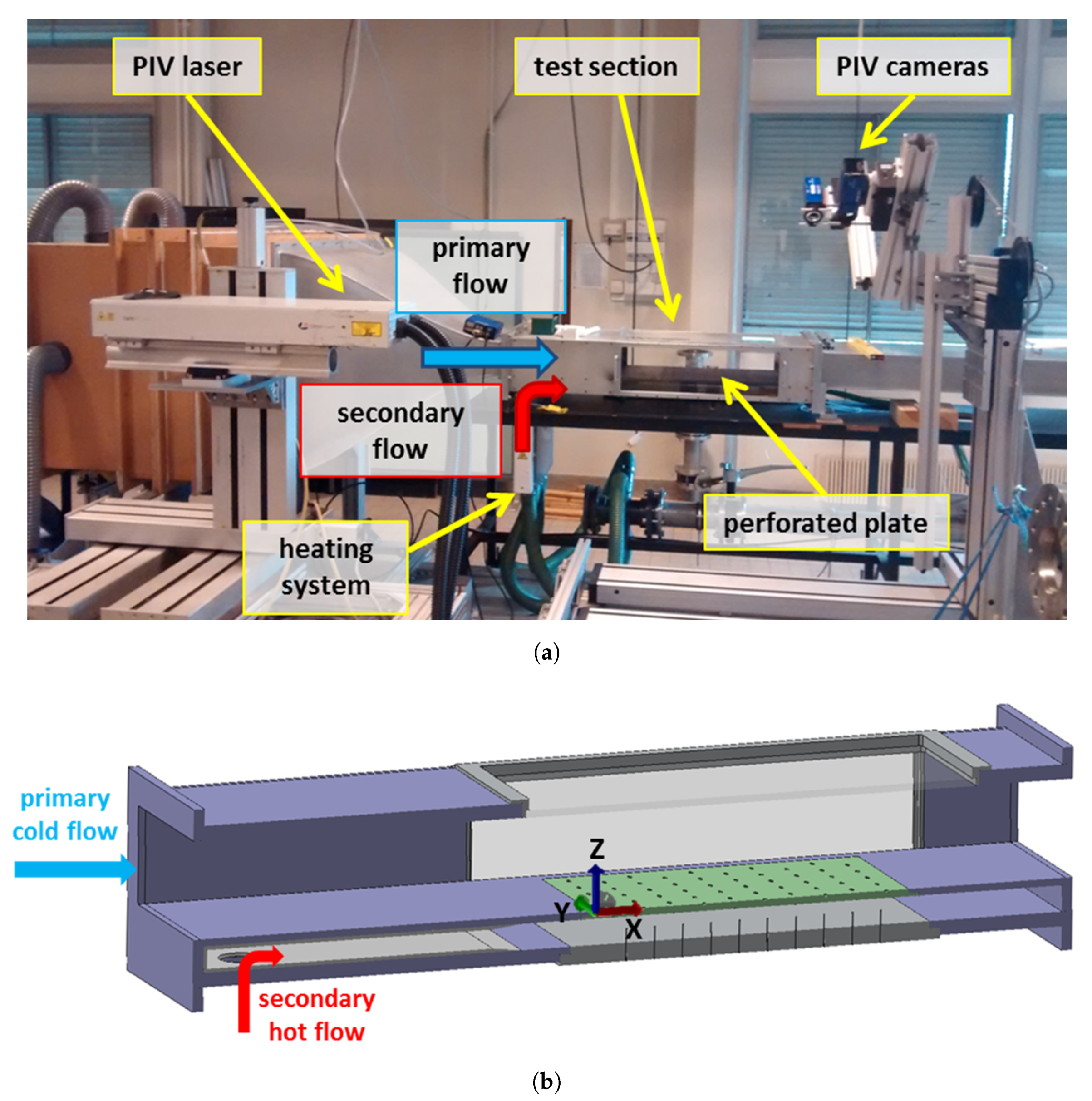
Figure 1. Set-up of the multiperforated plate experiment—In blue: main cold flow with a section of 448 × 135 m m 2 -In red: secondary hot flow with a section of 448 × 36 m m 2 . (a) Experimental apparatus with SPIV set-up for Z-plane acquisition; (b) Close-up view of the test section—Definition of the referential frame linked to the wind tunnel—The direction of the main flow is defined by X.
Energies 14 00613 g001
Figure 2. Geometrical parameters of the perforated plate.
Energies 14 00613 g002
Figure 3. Location of SPIV measurement planes—Note that X-position 0 refers to the upstream limit of the multi perforated plate.
Energies 14 00613 g003
Figure 4. Cold-wire experiment—Setup and probe.
Energies 14 00613 g004
Figure 5. Measurement box of the cold wire thermometry.
Energies 14 00613 g005
Figure 6. Heat transfer coefficient and adiabatic wall temperature estimation.
Energies 14 00613 g006
Figure 7. Infrared thermography set-up for wall heat transfer characterization.
Energies 14 00613 g007
Figure 8. IRTh measurement fields.
Energies 14 00613 g008
Figure 9. Heat flux distribution generated by the conductive paint.
Energies 14 00613 g009
Figure 10. Linear regression (average on the whole measurement zone).
Energies 14 00613 g010
Figure 11. Numerical conditions—Mesh quality and boundaries. (a) y + distribution near the hot (bottom) and cold (top) sides of the plate; (b) Boundary conditions prescribed.
Energies 14 00613 g011
Figure 12. Velocity fields for Z-plane Z = 5.8   mm .
Energies 14 00613 g012
Figure 13. SPIV versus CEDRE EBRSM Velocity fields for X-plane X = 73.5 mm localized on the 2nd row.
Energies 14 00613 g013aEnergies 14 00613 g013b
Figure 14. 3D reconstruction of the main flow on the 3rd row—The iso-surfaces are constructed for a velocity magnitude N equal to 5.7 m · s 1 .
Energies 14 00613 g014
Figure 15. Velocity fields for Z-plane Z = 11.8 mm.
Energies 14 00613 g015
Figure 16. Velocity fields for Z-plane Z = 26.8 mm.
Energies 14 00613 g016
Figure 17. Velocity fields for X-plane X = 138 mm localized midway between the 3rd and 4th rows.
Energies 14 00613 g017
Figure 18. Velocity profile 5 mm above the wall: comparison between experiment (SPIV), SST and EBRSM simulations.
Energies 14 00613 g018
Figure 19. Turbulent kinetic energy map at 4th row.
Energies 14 00613 g019
Figure 20. Experimental and numerical non-dimensional temperature field (constant-X planes).
Energies 14 00613 g020
Figure 21. Experimental and numerical non-dimensional temperature field ( Z = 5 mm plane).
Energies 14 00613 g021
Figure 22. Experimental and numerical non-dimensional temperature field ( Y = 61.15 mm plane).
Energies 14 00613 g022
Figure 23. Wall temperature of the multiperforated plate without electrical heating.
Energies 14 00613 g023
Figure 24. Experimental and numerical HTC and adiabatic wall temperature maps on top and bottom surface of multiperforated plate.
Energies 14 00613 g024
Figure 25. Sensitivity of HTC and adiabatic temperature to HTC in the holes.
Energies 14 00613 g025
Figure 26. NHFR map.
Energies 14 00613 g026
Figure 27. Comparison of laterally averaged HTC and adiabatic effectiveness.
Energies 14 00613 g027
Table 1. Uncertainty of wall heat transfer characterization.
Primary FlowSecondary Flow
HTC 7 % 9 %
η a w 0.04 0.05
Publisher’s Note: MDPI stays neutral with regard to jurisdictional claims in published maps and institutional affiliations.