Reviewing the Exergy Analysis of Solar Thermal Systems Integrated with Phase Change Materials


Abstract
:1. Introduction
Thermodynamic Performance of Energy Systems
2. Application of Exergy Analysis in PCM for Solar Systems
2.1. Evaluation of Exergy Equations
2.1.1. Water Heating
2.1.2. Solar Green House
2.1.3. Power Generation
2.1.4. Solar Dryers/Air Heaters
2.1.5. Solar Stills
2.1.6. Space Conditioning
2.1.7. Solar Cooker
2.1.8. Solar Refrigeration
3. Discussion
4. Conclusions
Author Contributions
Funding
Conflicts of Interest
Nomenclature and Subscripts
| Nomenclature | |
| T | temperature (°C) |
| M | molecular mass |
| M | molecular mass of the vapor |
| P | internal moisture pressure or pressure |
| R | universal gas constant |
| X0 | molar ratio |
| S | specific entropy (J kg−1 s−1) |
| t | time (s) or thickness (m) |
| m | mass of the PCM (kg) |
| ṁ | mass flow rate of air (kg s−1) |
| l | latent heat of the PCM |
| V | solid volume of the PCM |
| ρs | solid density of the PCM |
| h | latent heat |
| Cp or C or c | specific capacity |
| U or h | overall heat transfer coefficient (W m−2 K−1) |
| A | area (m2) |
| v | volumetric flow rate, m3/s |
| ρ | density, kg/m3 |
| PCM | phase change material |
| Q | rate of heat transfer in W |
| m | mass of PCM |
| the mass flow rate | |
| ʎ | latent heat of fusion |
| R | gas constant |
| IT | solar radiation (W/m−2) |
| ηo | optical yield |
| ʎfg | the latent heat of vaporization |
| i | properties of the PCMs |
| k | thermal conductivity of the heat transfer fluid |
| hi | the inside heat transfer coefficient |
| ho | outside heat transfer coefficient |
| ro | outer radius of the storage tank |
| ri | inner radius of the storage tank, heat |
| v | the kinematic viscosity |
| l | the length of storage tank and |
| LP | the latent heat of melting of the PCM |
| Subscripts | |
| s | Sun or solid or surface, |
| w | water |
| g or v | vapour |
| f | fluid |
| I | inlet or insulation |
| o | outlet |
| a | air or ambient |
| HTF | heat transfer fluid |
| p | thermal storage material or absorber plate |
| e or 0 | environment |
| m | melting |
| findisch | final discharge |
| indisch | initial discharge |
| b | basin |
| l | liquid |
References
- Simo-Tagne, M.; Ndukwu, M.C.; Zoulalian, A.; Bennamoun, L.; Kifani-Sahban, F.; Rogaume, Y. Numerical analysis and validation of a natural convection mix-mode solar dryer for drying red chili under variable conditions. Renew. Energy 2020, 151, 659–673. [Google Scholar]
- Ndukwu, M.C.; Bennamoun, L.; Abam, F.I. Experience of solar drying in Africa: Presentation of designs, operations and models. Food Eng. Rev. 2018, 10, 211–244. [Google Scholar]
- Ndukwu, M.C.; Onyenwigwe, D.; Abam, F.I.; Eke, A.B.; Dirioha, C. Development of a low-cost wind-powered active solar dryer integrated with glycerol as thermal storage. Renew. Energy 2020, 154, 553–568. [Google Scholar]
- Ndukwu, M.C.; Bennamoun, L.; Abam, F.I.; Eke, A.B.; Ukoha, D. Energy and exergy analysis of a solar dryer integrated with sodium sulfate decahydrate and sodium chloride as thermal storage medium. Renew. Energy 2017, 113, 1182–1192. [Google Scholar]
- Kenisarin, M.; Mahkamov, K. Solar energy storage using phase change materials. Renew. Sustain. Energy Rev. 2007, 11, 1913–1965. [Google Scholar]
- Oliver, A.; Neila, F.J.; García-Santos, A. PCM choosing and classification according to their characteristics for their application for thermal energy storage systems. Mater. Constr. 2010, 62, 131–140. [Google Scholar]
- Sharma, S.D.; Sagara, K. Latent heat storage materials and systems: A review. Int. J. Green Energy 2005, 2, 1–56. [Google Scholar]
- Hasnain, S.M. Review on sustainable thermal energy technologies, Part II: Cool 6 thermal storage. Energy Conv. Manag. 1998, 39, 1139–1153. [Google Scholar]
- Ndukwu, M.C.; Bennamoun, L. Potential of integrating Na2SO4 · 10H2O pellets in solar drying system. Dry Technol. 2018, 36, 1017–1030. [Google Scholar]
- Du, K.; Calautit, J.; Wang, Z.; Wu, Y.; Liu, H. A review of the applications of phase change materials in cooling, heating and power generation in different temperature ranges. Appl. Energy 2018, 220, 242–273. [Google Scholar]
- Marliacy, P.; Solimando, R.; Bouroukba, M.; Schuffenecker, L. Thermodynamics of crystallization of sodium sulphate decahydrate in H2O±NaCl±Na2SO4: Application to Na2SO4.10H2O-based latent heat storage materials. Thermochim. Acta. 2000, 344, 85–94. [Google Scholar]
- Ortega, A.R.; Carmona, M. Exergy analysis of a flat plate solar collector with latent heat storage by phase change material for water heating applications at low temperature. Contemporary Urban. Aff. 2017, 1, 43–48. [Google Scholar]
- Ghiami, A.; Kianifar, A.; Aryana, K.; Edalatpour, M. Energy and Exergy Analysis of a Single-Pass Sequenced Array Baffled Solar Air Heater with Packed Bed Latent Storage Unit for Nocturnal Use. Heat Transfer Asian Res. 2017, 46, 546–568. [Google Scholar] [CrossRef]
- Nkwetta, D.N.; Haghighat, F. Thermal energy storage with phase change material- A state of the art review. Sustain. Cities Soc. 2014, 10, 87–100. [Google Scholar]
- Li, Y.Q.; He, Y.; Wang, Z.; Xu, C.; Wanga, W. Exergy analysis of two phases change materials storage system for solar thermal power with finite-time thermodynamics. Renew. Energy 2012, 39, 447–454. [Google Scholar]
- Abdulmunem, R.A.; Jaba, M.H.; Samin, P.M.; Rahman, H.A.; Hussien, H.A. Analysis of Energy and Exergy for the Flat Plate Solar Air Collector with Longitudinal Fins Embedded in Paraffin Wax Located in Baghdad Center. Int. J. Heat. Technol. 2019, 37, 1180–1186. [Google Scholar]
- Hasnain, S.M. Review on sustainable thermal energy storage technologies. Part I: Heat storage materials and techniques. Energy Conver Manag. 1988, 39, 1127–1138. [Google Scholar]
- Zalba, B.; Marin, J.M.; Cabeza, L.F.; Mehling, H. Review on thermal energy storage with phase change: Materials, heat transfer analysis and applications. Appl. Therm. Eng. 2003, 23, 251–283. [Google Scholar]
- Kalogirou, S.A.; Karellas, S.; Badescu, V.; Braimakis, K. Exergy analysis on solar thermal systems: A better understanding of their sustainability. Renew. Energy 2016, 85, 1328–1333. [Google Scholar]
- Mehling, H.; Cabeza, L.F. Heat and Cold Storage with PCM, 1st ed.; Berlin Springer Publication Corporation: Berlin, Germany, 2008. [Google Scholar]
- Mahinian, O.; Kianifar, A.; Kalogirou, S.A.; Pop, I.; Wongwises, S. A review of the applications of nanofluids in solar energy. Int. J. Heat. Mass. Trans. 2013, 57, 582–594. [Google Scholar]
- Bozorgan, N.; Shafahi, M. Performance evaluation of nanofluids in solar energy: A review of the recent literature. Micro. Nano Syst. Lett. 2015, 3, 1–15. [Google Scholar] [CrossRef] [Green Version]
- Liu, L.; Su, D.; Tang, Y.; Fang, G. Thermal conductivity enhancement of phase change materials for thermal energy storage: A review. Renew. Sustain. Energy Rev. 2016, 62, 305–317. [Google Scholar] [CrossRef]
- Jarimi, H.; Aydin, D.; Yanan, Z.; Ozankaya, G.; Chen, X.; Riffat, S. Review on the recent progress of thermochemical materials and processes for solar thermal energy storage and industrial waste heat recovery. Int. J. Low-Carbon Technol. 2019, 14, 44–69. [Google Scholar] [CrossRef] [Green Version]
- Oró, E. Review on phase change materials (PCMs) for cold thermal energy storageApplications. Appl. Energy 2012, 99, 513–533. [Google Scholar] [CrossRef] [Green Version]
- Saito, A. Recent advances in research on cold thermal energy storage. Int. J. Refrig. 2002, 25, 177–189. [Google Scholar] [CrossRef]
- Zhai, X.Q.; Wang, X.L.; Wang, T.; Wang, R.Z. A review on phase change cold storage in air-conditioning system: Materials and applications. Renew. Sustain. Energy Rev. 2013, 22, 108–120. [Google Scholar] [CrossRef]
- Jegadheeswaran, S.; Pohekar, S.D.; Kousksou, T. Exergy based performance evaluation of latent heat thermal storage system: A review. Renew. Sustain. Energy Rev. 2010, 14, 2580–2595. [Google Scholar] [CrossRef]
- Ranjan, K.R.; Kaushik, S.C.; Panwar, N.L. Energy and exergy analysis of passive solar distillation systems. Int. J. Low-Carbon Technol. Adv. Access 2013, 11, 211–221. [Google Scholar] [CrossRef] [Green Version]
- Kianifar, A.; Heris, S.Z.; Mahian, O. Exergy and economic analysis of a pyramid-shaped solar water purification system: Active and passive cases. Energy 2012, 38, 31–36. [Google Scholar] [CrossRef]
- Kurtbas, I.; Durmus, A. Efficiency and exergy analysis of a new solar air heater. Renew. Energ. 2004, 29, 1489–1501. [Google Scholar] [CrossRef]
- Domański, R.; Fellah, G. Exergy as A Tool for Designing and Operating Thermal Storage Units; Biuletyn Instytutu Techniki Cieplnej Politechniki Warszawskiej: Warsaw, Poland, 1995. [Google Scholar]
- Aghbaslou, F.; Badia, F.; Illa, J. Exergetic optimization of solar collector and thermal energy storage system. Int. J. Heat. Mass. Trans. 2006, 49, 1255–1263. [Google Scholar] [CrossRef]
- Hatami, S.; Payehaneh, G.; Mehrpanahi, A. Energy and exergy analysis of an indirect solar dryer based on a dynamic model. J. Clean. Prod. 2020, 244, 118809. [Google Scholar] [CrossRef]
- Ndukwu, M.C.M.; Simo-Tagne, F.I.; Abam, O.S.; Onwuka, S.; Prince, L. Bennamoun. Exergy, environmental and economic analysis of hybrid solar-biomass dryer integrated with copper tubing as heat exchanger. Heliyon 2020, 6, e03401. [Google Scholar] [CrossRef] [PubMed]
- El-dessouky, H.; Faisal, A. Effectiveness of a thermal energy storage system using phase-change materaials. Energy Convers. Manag. 1997, 38, 601–607. [Google Scholar] [CrossRef]
- Szargut, J.; Morris, D.R.; Steward, F.R. Exergy Analysis of Thermal, and Metallurgical Processes; Hemisphere Publishing Corporation: New York, NY, USA, 1988. [Google Scholar]
- Szargut, J. International Progress in Second Law Analysis. Energy 1980, 5, 709–718. [Google Scholar] [CrossRef]
- Bejan, A. The concept of irreversibility in heat exchanger design: Counter flow heat exchangers for gas-to-gas. ASME J. Heat. Trans. 1977, 99, 374–380. [Google Scholar] [CrossRef]
- Bejan, A. Entropy Generation through Heat and Fluid Flow; John Wiley & Sons: New York, NY, USA, 1982. [Google Scholar]
- Bjurstrom, H.; Carlson, B. An exergy analysis of sensible and latent heat storage. Heat. Recov. Syst. 1985, 5, 233–250. [Google Scholar] [CrossRef]
- Krane, R.J. A second law analysis of the optimum design and operation of thermal energy storage systems. Int. J. Heat Trans. 1987, 30, 43–57. [Google Scholar] [CrossRef]
- Marken, C. Solar collectors: Behind the glass. Home Power 2009, 133, 70–76. [Google Scholar]
- Brian, N. Solar Water Heaters: A Review of Systems Research and Design Innovation. Green 2001, 1, 189–207. [Google Scholar]
- Kocaa, A.; Oztop, H.F.; Koyunc, T.; Varol, Y. Energy and exergy analysis of a latent heat storage system with phase change material for a solar collector. Renew. Energy 2008, 33, 567–574. [Google Scholar] [CrossRef]
- Omara, A.A.M.; Abuelnuor, A.A.A.; Dafaallah, M.A.A.; Ali, A.M.A.; Alshoubli, M.A.M. Energy and Exergy analysis of solar water heating system integrated with phase change material (PCM). In Proceedings of the 2018 International Conference on Computer, Control, Electrical, and Electronics Engineering (ICCCEEE), Khartoum, Sudan, 12–14 August 2018. [Google Scholar]
- Yang, L.; Zhang, X. Performance of a new packed bed using stratified phase change capsules. Int. J. Low-Carbon Technol. 2012, 7, 208–214. [Google Scholar] [CrossRef] [Green Version]
- Singh, P.; Singh, H. Numerical Investigation of a New Packed Bed Storage System Filled with Different Phase Change Materials. Int. J. Adv. Manag. Technol. Eng. Sci. 2018, 8, 530–536. [Google Scholar]
- Gürtürk, M.; Koca, A.; Öztop, H.F.; Varol, Y.; Şekerci, M. Energy and exergy analysis of a heat storage tank with novel eutectic phase change material layer of a solar heater system. Int. J. Green Energy 2017, 14, 1073–1080. [Google Scholar] [CrossRef]
- Kim, K.; Yoon, J.; Kwon, H.; Han, J.; Son, J.E.; Nam, S.; Giacomelli, G.A.; Lee, I.B. 3-D CFD analysis of relative humidity distribution in greenhouse with a fog cooling system and refrigerative dehumidifiers. Biosyst. Eng. 2008, 100, 245–255. [Google Scholar] [CrossRef]
- Demirel, Y.; Ozturk, H.H. Thermoeconomics of seasonal latent heat storage system.2007. Int. J. Energy Res. 2006, 30, 1001–1012. [Google Scholar] [CrossRef] [Green Version]
- Demirel, Y. Heat Storage by Phase Changing Materials and Thermoeconomics. In Thermal Energy Storage for Sustainable Energy Consumption; Paksoy, H.O., Ed.; Springer: Berlin/Heidelberg, Germany, 2007; pp. 133–151. [Google Scholar]
- Mahfuz, M.H.; Kamyar, A.; Afshar, O.; Sarraf, M.; Anisur, M.R.; Kibria, M.A.; Saidur, R.; Metselaar, I.H.S.C. Exergetic analysis of a solar thermal power system with PCM storage. Energy Conv. Manag. 2014, 78, 486–492. [Google Scholar] [CrossRef]
- Manfrida, G.; Secchi, R.; Stanczyk, K. Modelling and simulation of phase change material latent heat storages applied to a solar-powered Organic Rankine Cycle. Appl. Energy 2016, 179, 378–388. [Google Scholar] [CrossRef] [Green Version]
- Thomas, D.G.; Babu, S.; Gopic, S. Performance Analysis of a Latent Heat Thermal Energy Storage System for Solar Energy Applications. Procedia Technol 2016, 24, 469–476. [Google Scholar] [CrossRef] [Green Version]
- Edalatpour, M.; Kianifar, A.; Aryana, K.; Tiwari, G.N. Energy, exergy, and cost analyses of a double-glazed solar air heater using phase change material. J. Renew. Sust. Energy 2016, 8, 015101. [Google Scholar] [CrossRef]
- Bouadila, S.; Lazaar, M.; Skouri, S.; Kooli, S.; Farhat, A. Energy and exergy analysis of a new solar air heater with latent storage energy. Int. J. Hydrogen Energy 2014, 39, 15266–15274. [Google Scholar] [CrossRef]
- Asbik, M.; Ansari, O.; Bah, A.; Zari, N.; Mimet, A.; El-Ghetany, H. Exergy analysis of solar desalination still combined with heat storage system using phase change material (PCM). Desalin 2016, 381, 26–37. [Google Scholar] [CrossRef]
- Yousef, M.S.; Hassan, H. Energetic and exergetic performance assessment of the inclusion of phase change materials (PCM) in a solar distillation system. Energy Convers Manag. 2019, 179, 349–361. [Google Scholar] [CrossRef]
- Torchia-Nunez, J.C.; Porta-Gandara, M.A.; Cervantes-de Gortari, J.G. Exergy analysis of a passive solar still. Renew. Energy 2008, 33, 608–616. [Google Scholar] [CrossRef]
- Deniz, E.; Çınar, S. Energy, exergy, economic and environmental (4E) analysis of a solar desalination system with humidification-dehumidification. Energy Convers Manag. 2016, 126, 12–19. [Google Scholar] [CrossRef]
- Deniz, E. Energy and exergy analysis of flat plate solar collector-assisted active solar distillation system. Desal. Water Treat. 2016, 57, 24313–24321. [Google Scholar] [CrossRef]
- Singh, D.B.; Tiwari, G.N. Exergoeconomic, enviroeconomic and productivity analyses of basin type solar stills by incorporating N identical PVT compound parabolic concentrator collectors: A comparative study. Energy Convers Manag. 2017, 135, 129–147. [Google Scholar] [CrossRef]
- Sarhaddi, F.; Tabrizi, F.F.; Zoori, H.A.; Hossein, S.A.; Mousavi, S. Comparative study of two weir type cascade solar stills with and without PCM storage using energy and exergy analysis. Energy Convers Manag. 2017, 133, 97–109. [Google Scholar] [CrossRef]
- Solar Energy at Home (SHE). Solar Space Heating—Solar Energy at Home. 2020. Available online: www.solar-energy-at-home.com›solar-space-heating (accessed on 14 May 2020).
- Ma, Z.; Ren, H.; Sun, Z. Energy and exergy analysis of a desiccant cooling system integrated with thermal energy storage and photovoltaic/thermal-solar air collectors. Sci. Technol. Built Environ. 2020, 26, 12–27. [Google Scholar] [CrossRef]
- Arul Kumar, A.; Babu, B.G.; Mohanraj, M. Experimental investigations on a forced convection solar air heater using packed bed absorber plates with phase change materials. Int. J. Green Energy 2017, 14, 1238–1255. [Google Scholar] [CrossRef]
- Solomon, L.; Oztekin, A. Exergy analysis of cascaded encapsulated phase change material— High-temperature thermal energy storage systems. J. Energy Storage 2016, 8, 12–26. [Google Scholar] [CrossRef]
- Mehla, N.; Yadav, A. Thermal analysis on charging and discharging behaviour of a phase change material-based evacuated tube solar air collector. Indoor Built Environ. 2018, 27, 156–172. [Google Scholar] [CrossRef]
- Sharma, S.D.; Iwata, T.; Kitano, H.; Sagara, K. Thermal performance of a solar cooker based on an evacuated tube solar collector with a PCM storage unit. Solar Energy 2005, 78, 416–426. [Google Scholar] [CrossRef]
- Pal, M.; Chauhan, A.K. Experimental Investigation of Thermal energy storage with phase changing material. Int. J. Adv. Res. Innov. 2019, 7, 33–37. [Google Scholar]
- Koronaki, I.P.; Papoutsis, E.G.; Papaefthimiou, V.D. Thermodynamic modeling and exergy analysis of a solar adsorption cooling system with cooling tower in Mediterranean conditions. Appl. Therm. Eng. 2016, 99, 1027–1038. [Google Scholar] [CrossRef]
- Khana, M.M.A.; Saidur, R.; Al-Sulaiman, F.A. A review for phase change materials (PCMs) in solar absorption refrigeration systems. Renew. Sust. Energy Rev. 2017, 76, 105–137. [Google Scholar] [CrossRef]
- Miyazaki, T.; Akisawa, A. The influence of heat exchanger parameters on the optimum cycle time of adsorption chillers. Appl. Therm. Eng. 2009, 29, 2708–2717. [Google Scholar] [CrossRef]
- Ghorbani, B.; Mehrpooy, M. Concentrated solar energy system and cold thermal energy storage (process development and energy analysis). Sust. Energy Technol. Assess. 2020, 37, 100607. [Google Scholar] [CrossRef]
- Kousksou, T.; Strub, F.; Lasvignottes, J.S.; Jamil, A.; Bedecarrats, J.P. Second law analysis of latent thermal storage for solar system. Sol. Energy Mater. Sol. Cells 2007, 91, 1275–1281. [Google Scholar] [CrossRef]
- Jegadheeswaran, S.; Pohekar, S.D. Numerical investigations on the performance enhancement of a latent heat thermal storage unit with particle laden phase change material. In Proceedings of the 6th International Conference on Computational Heat and Mass Transfer, Guangzhou, China, 18–19 May 2009. [Google Scholar]
- Jegadheeswaran, S.; Pohekar, S.D. Performance enhancement in latent heat thermal storage system: A review. Renew. Sust. Energy Rev. 2009, 13, 2225–2244. [Google Scholar] [CrossRef]


| Authors [Reference] | Nature of Studies | Aim | PCM Type | HTF | Results |
|---|---|---|---|---|---|
| Aghbasolou et al. [21] | Theoretical studies | Optimization of thermodynamic performance of solar thermal energy storage system with PCM slabs based on exergy analysis | Rubi-therm | Water | Melting temperature affected Irreversibility with lower value at higher melting point and lower value at lower melting point which gave better quality energy |
| Koca et al. [45] | Experimental studies | Analysis of the energy and exergy of a latent heat storage system with PCM for a solar collector | CaCl2.6H2O | Water | Low exergy efficiency of 2.2% was recorded due to the small area occupied by PCM compared to the collector which resulted in low outlet temperature |
| Singh and Singh [48] | Theoretical studies | numerical investigation of stuffed bed utilizing a stratified PCM | Paraffin, Hybrid wax, Bee wax | Water | Not validated |
| Ortega and Carmona [12] | Experimental studies | Performance of exergy analysis to determine the potential for the useful work presented by used PCM | paraffin wax | air | 13.2% average exergetic efficiency was obtained for of low radiation days, 20.56% was recorded for medium radiation days, and 18.6% was obtained for high radiation days |
| Yang and Zhan [47] | Theoretical studies | To presents a theoretical study of a packed bed using a stratified PCM | C21H44, C22H46, C24H50 | Water | The PCM bed presented lower irreversibility compared to single packed bed. Higher efficiency was recorded in the simultaneous charging and discharging for stratified packed bed compared to single packed bed |
| Omara et al. [46] | Experimental studies | Investigation of the thermodynamic performance of solar water heating system incorporated with PCM | Parafin wax | Water | Addition of PCM increase the exergy output which led to lower exergy destruction. Therefore, the PCM improved the exergy efficiency |
| Gürtürk et al. [49] | Comparative experimental studies | To compare exergetic and energetic efficiency with and without the PCM | Mixture of Na2HPO4·12H2O) and NH4, Al(SO4)·6H2O) to form a eutectic PCM | Water | exergy analysis recorded highest efficiency of 22% for the heat storage tank integrated with the PCM |
| Authors [Reference] | Nature of Studies | Aim | PCM Type | HTF | Results |
|---|---|---|---|---|---|
| Demirel and Ozturk [51] | Theoretical and experimental studies | Thermo economic analysis for a seasonal PCM for heating a Greenhouse | Paraffin wax | Air | Thermo-economic analysis was used to obtain feasible design which was accounted for by the cost of exergy within |
| Authors [Reference] | Nature of Studies | Aim | PCM Type | HTF | Results |
|---|---|---|---|---|---|
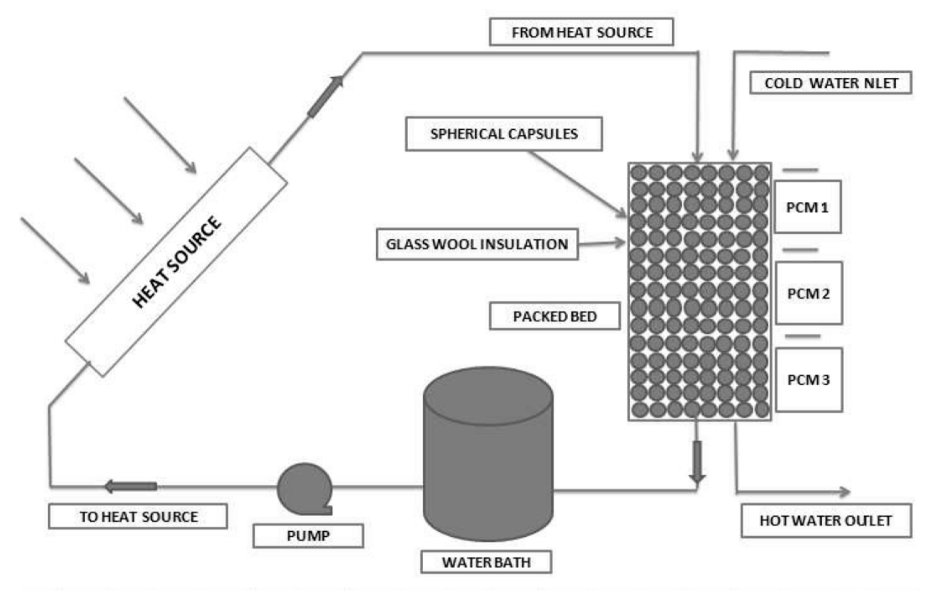
| Manfrida et al. [54] | parametric studies | Modelling of a PCM spheres filled storage tank for power generation | Erythritol | water | Simulated result obtained with mixed TRNSYS/EES software was in good agreement with experimental data obtained from literature. The Exergy efficiency obtained was 68% for mutually operational phases with the net efficiency of 3.9% |
| Li et al. [15] | Theoretical studies | Development of a theoretical model to obtain the net exergetic efficiency of serially placed double PCM storage system based on finite-time thermodynamics | Not indicated | air | The overall exergetic efficiency was improved with double PCM placed in series than single PCM. Melting temperature had different effects on the net exergetic efficiency |
| Mahfuz et al. [53] | Comparation of experimental and theoretical studies | thermodynamic performance analysis for a solar thermal power plant located in Shiraz, Iran | H190, H220, H230, H250 | oil | About 30% net higher exergy efficiency can be obtained for using PCM storage along with the solar collector |
| Authors [Reference] | Nature of Studies | Aim | PCM Type | HTF | Results |
|---|---|---|---|---|---|
| Ndukwu et al. [4] | Experimental studies | Comparative performance analysis based on exergy efficiency of a solar dryer integrated with or without wind powered fan and PCM | Glycerol | air | Lower exergy efficiency was obtained for solar dryers with PCM |
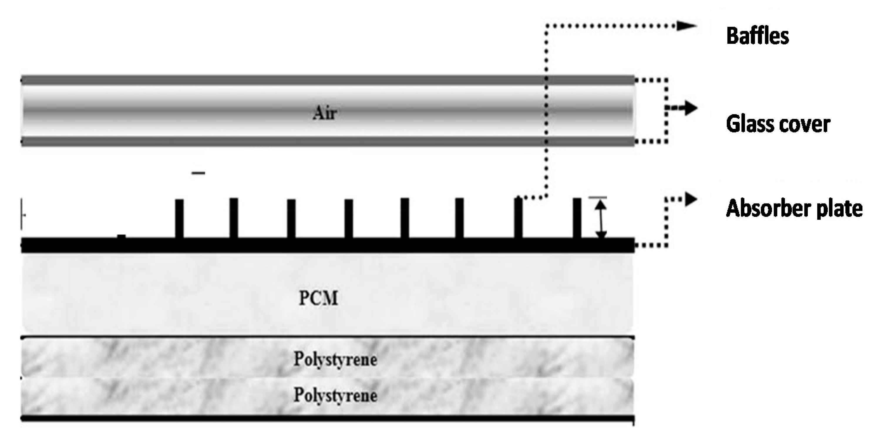
| Ghiami et al. [13] | Experimental and theoretical studies | Experimental investigation a single-pass double-glazed solar air heater with the use of packed bed PCM | Paraffin wax | air | The dailyExergy efficiency varied between 10.7% and 19.5% |
| Bouadila et al. [57] | Experimental studies | To experimentally investigate the amount of PCM heat for a night use with Solar Air Heater with Latent Sto) using spherically encapsulate PCM as a packed-bed under the absorber | Capsule (AC27) | air | The exergy efficiency of the system varied between 13% and 25% daily |
| Edalatpour et al. [56] | Experimental and theoretical studies | To present and thermodynamic evaluate solar air heater device with special configuration and PCM placed under the absorber | Paraffin wax | Air | The exergy efficiency varied between 14.45% and 26.34% daily |
| Ndukwu et al. [4] | Experimental and theoretical studies | To build cheap solar dryers with available local building materials incorporating a PCM | Na2SO4.10H2O | Air | The exergy efficiency the system using PCM during the off-sunshine hours and net exergy-efficiency of the entire drying duration were 81.19 and 66.82% for the two process |
| Authors [Reference] | Nature of Studies | Aim | PCM Type | HTF | Results |
|---|---|---|---|---|---|
| Sarhaddi et al. [64] | Theoretical analysis | Comparative performance of thermodynamic performance of two weir type cascade solar stills integrated with and without PCM thermal storage for different cloudy conditions | Paraffin wax | water | The highest exergy efficiencies obtained with PCM was 8.59% during the semi-cloudy day and therefore preferred due to high exergy efficiencies. The irreversibility rate of collector absorber was is 83.1% and 78.8% of the whole systems on a typical hot day for the two considered configurations |
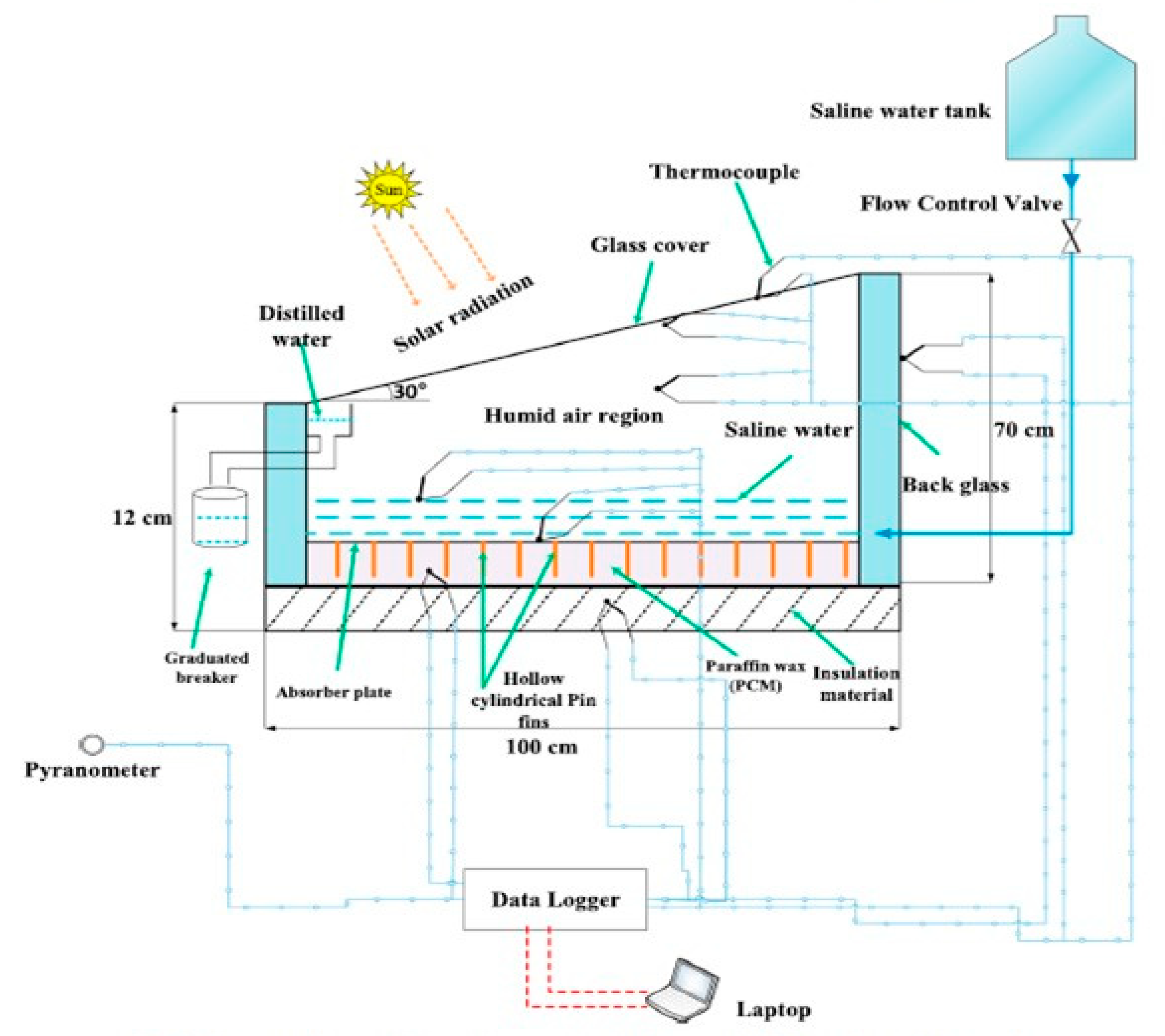
| Asbik et al. [58] | Theoretical studies | Exergy analysis of a passive solar still equipped with PCM thermal storage | Paraffin wax | water | The PCM increases the water yield and lowers the exergy efficiency. the instantaneous exergy efficiency of the system was less than 5%, but can increase to over 80% during the night |
| Yousef and Hassan [59] | Comparative Experimental studies | Thermodynamic evaluation of enhancement of solar still incorporated with PCMs | Paraffin wax | Solar still with PCM has higher exergetic efficiency |
| Authors [Reference] | Nature of Studies | Aim | PCM Type | HTF | Results |
|---|---|---|---|---|---|
| Thomas et al. [55] | Experimental studies | Thermodynamic evaluation of simulated solar space heating | Sodium thiosulfate pentahydrate | Air | Exergy efficiency of the system decreased with air flow rate and was very low |
| Solomon and Oztekin [68] | Comparative theoretical Studies | To determine the benefit of a system equipped with a multiple PCM | NaNO3, NaNO2, and KNO3 | air | The difference between the melting point of the PCMs and the inlet temperatures during charging and discharging greatly affected the performance of the system |
| Mehla and Yadav [69] | Experimental studies | To produce hot air for space heating in consecutive and simultaneous charging and discharging of the PCM using evacuated tube solar air collector | Acetamide | Water | The maximum average efficiency of 17.9% was obtained for the collector at a high air flow rate during simultaneously charging and discharging of the PCM |
| Abdulmunem et al. [16] | Comparative experimental studies | To analyze the thermodynamic performance of flat plate solar air collector with PCM and the effect of embedding fins into the PCM on the collector performance | Paraffin wax | Air | Compared with the collector without PCM, using of PCM reduces the losses of exergy of the collector |
| Arul Kumar et al. [67] | Experimental and theoretical studies | To compare the performance of a forced convention solar heater using different configuration (pin-fin, triangular and circular)of packed bed PCM thermal storage | Paraffin wax | air | Packed bed absorber plate configurations using PCM has 2-20% higher exergy efficiency when compared to flat absorber plate |
| Authors [Reference] | Nature of Studies | Aim | PCM Type | HTF | Results |
|---|---|---|---|---|---|
| Pal and Chauhan [71] | Comparative Experimental studies | Experiment investigation for solar cooking with parabolic solar concentrator and PCM to check their feasibility | paraffin wax | Air | The exergy efficiency of the system with PCM storage was higher than the system without PCM storage. |
Publisher’s Note: MDPI stays neutral with regard to jurisdictional claims in published maps and institutional affiliations. |
© 2021 by the authors. Licensee MDPI, Basel, Switzerland. This article is an open access article distributed under the terms and conditions of the Creative Commons Attribution (CC BY) license (http://creativecommons.org/licenses/by/4.0/).
Share and Cite
Ndukwu, M.C.; Bennamoun, L.; Simo-Tagne, M. Reviewing the Exergy Analysis of Solar Thermal Systems Integrated with Phase Change Materials. Energies 2021, 14, 724. https://doi.org/10.3390/en14030724
Ndukwu MC, Bennamoun L, Simo-Tagne M. Reviewing the Exergy Analysis of Solar Thermal Systems Integrated with Phase Change Materials. Energies. 2021; 14(3):724. https://doi.org/10.3390/en14030724
Chicago/Turabian StyleNdukwu, Macmanus Chinenye, Lyes Bennamoun, and Merlin Simo-Tagne. 2021. "Reviewing the Exergy Analysis of Solar Thermal Systems Integrated with Phase Change Materials" Energies 14, no. 3: 724. https://doi.org/10.3390/en14030724
APA StyleNdukwu, M. C., Bennamoun, L., & Simo-Tagne, M. (2021). Reviewing the Exergy Analysis of Solar Thermal Systems Integrated with Phase Change Materials. Energies, 14(3), 724. https://doi.org/10.3390/en14030724