Design and Position Control of Overhang-Type Rail Mover Using Dual BLAC Motor

Abstract
:1. Introduction
2. System Analysis
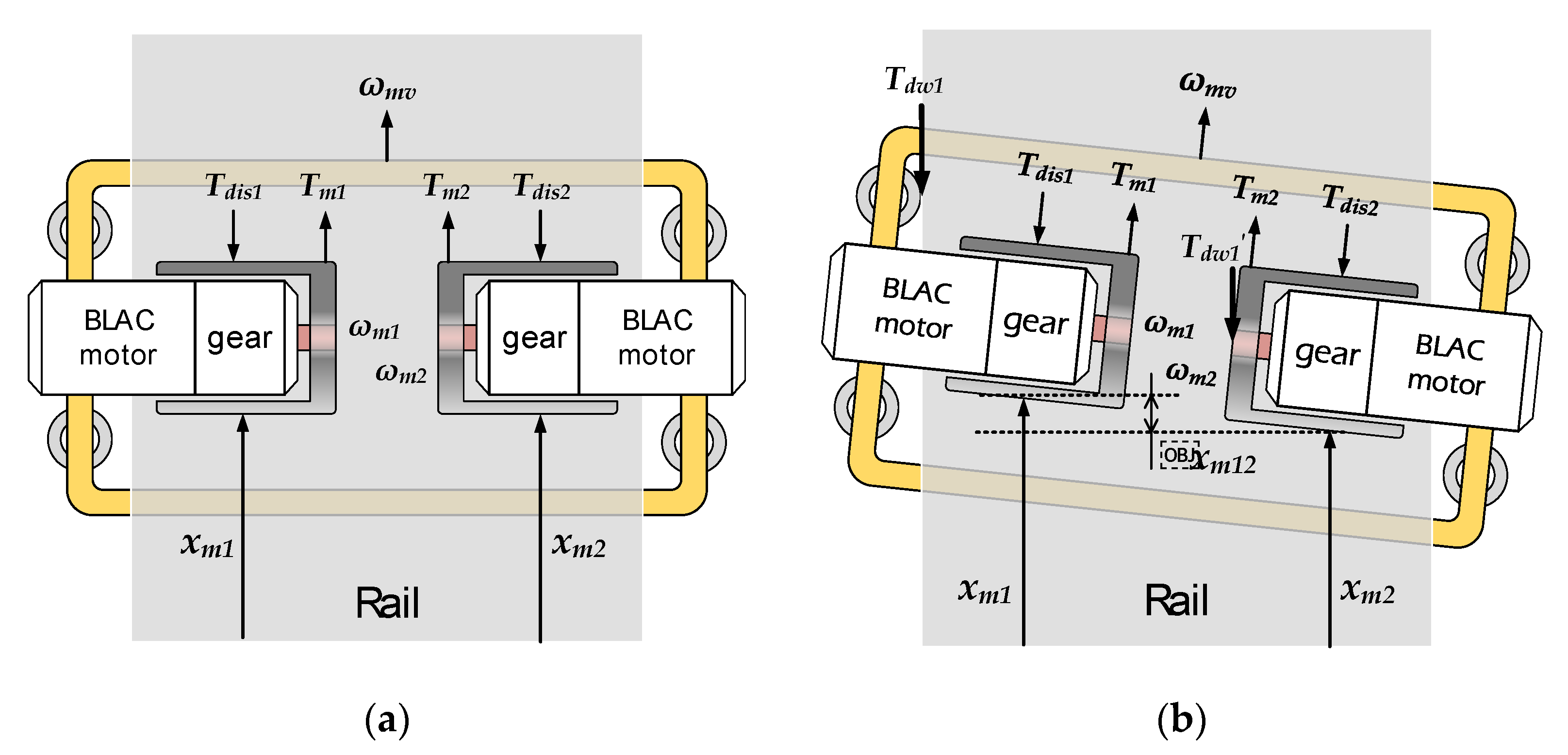
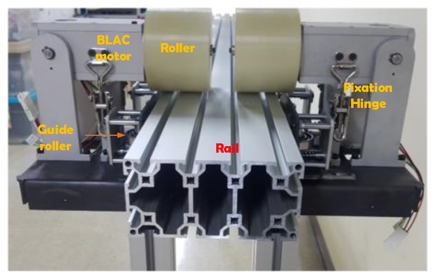
2.1. Mechanical Configuration
2.2. Mechanical Configuration
3. Analysis of Overhang-Type Rail Mover Using Dual BLAC Motors
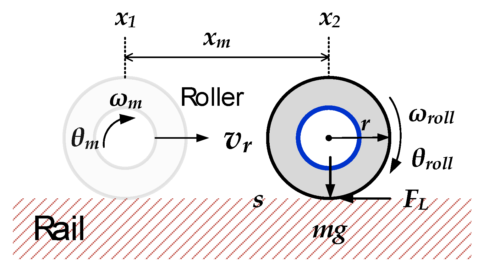
3.1. Mechanical Analysis of the Proposed Structure
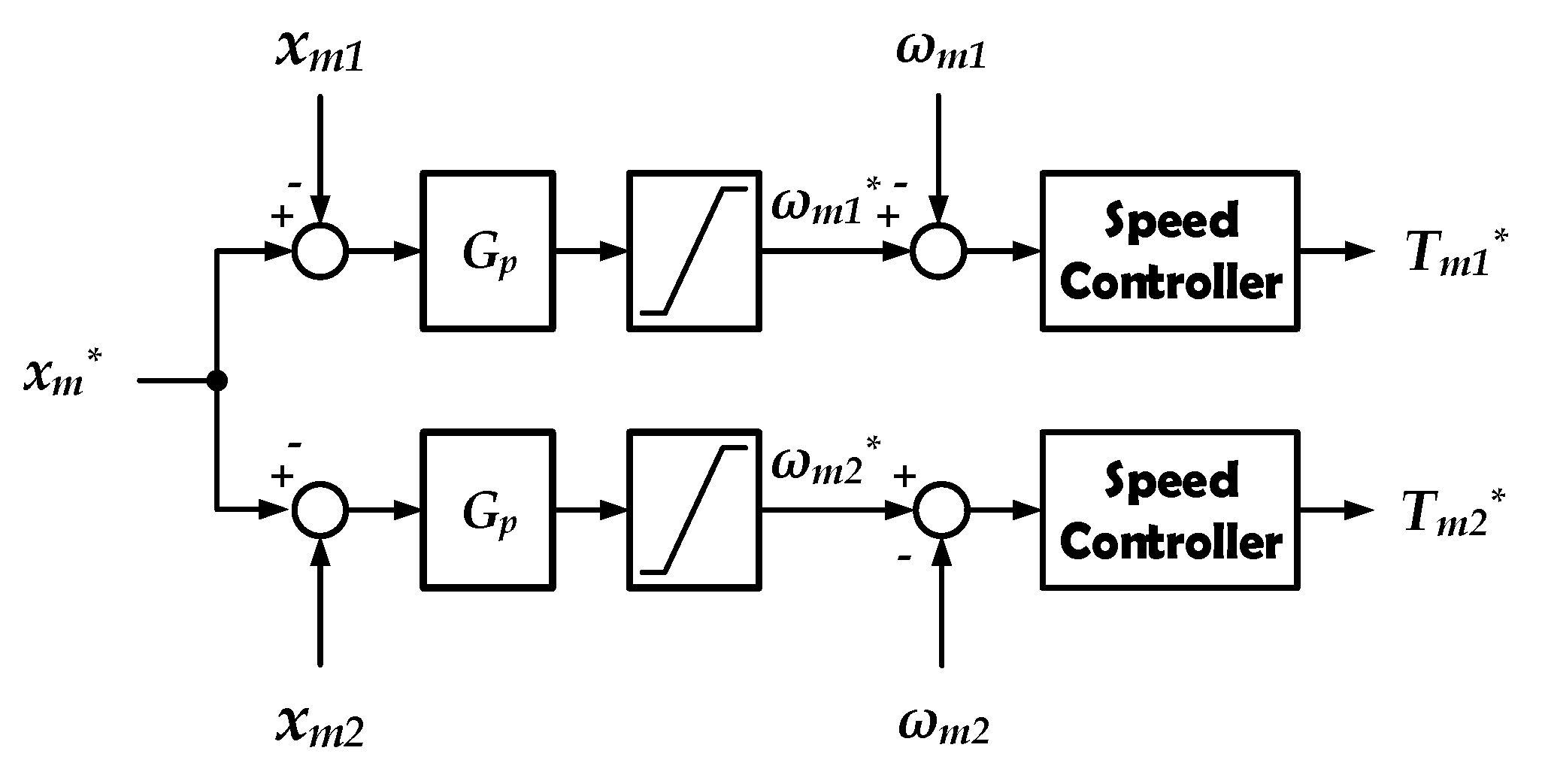
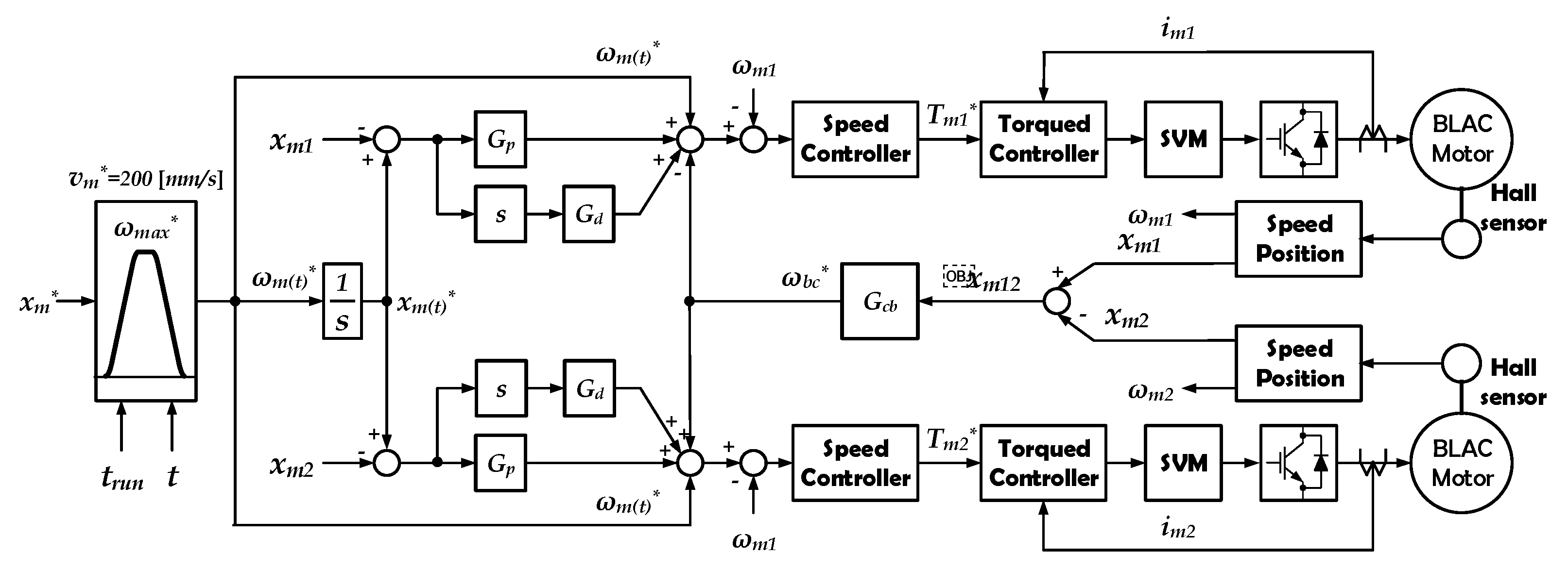
3.2. Position Control of Dual BLAC Motor Drives
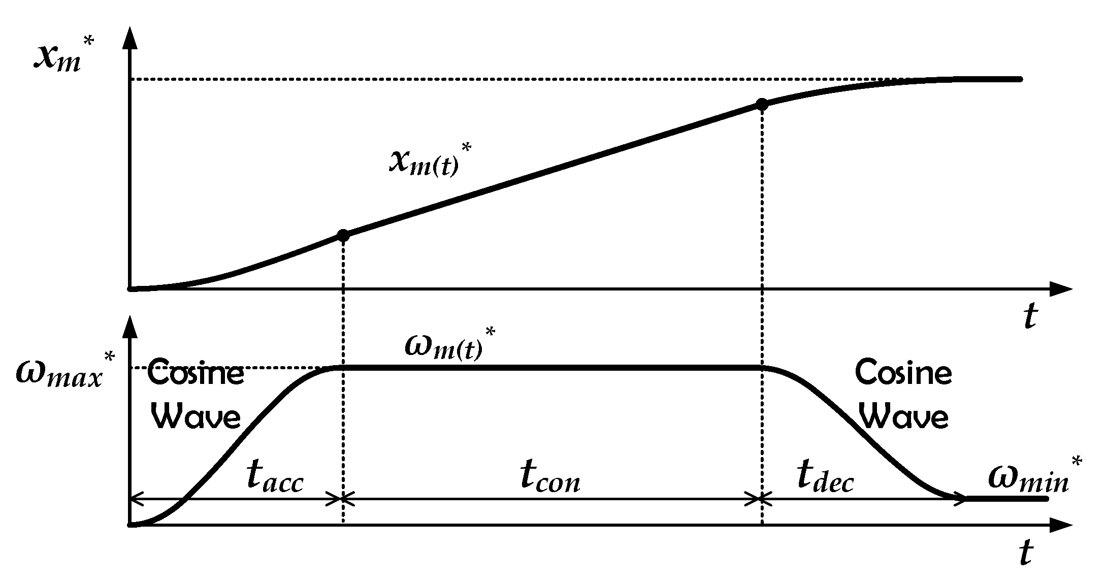
4. Proposed Position Control Scheme
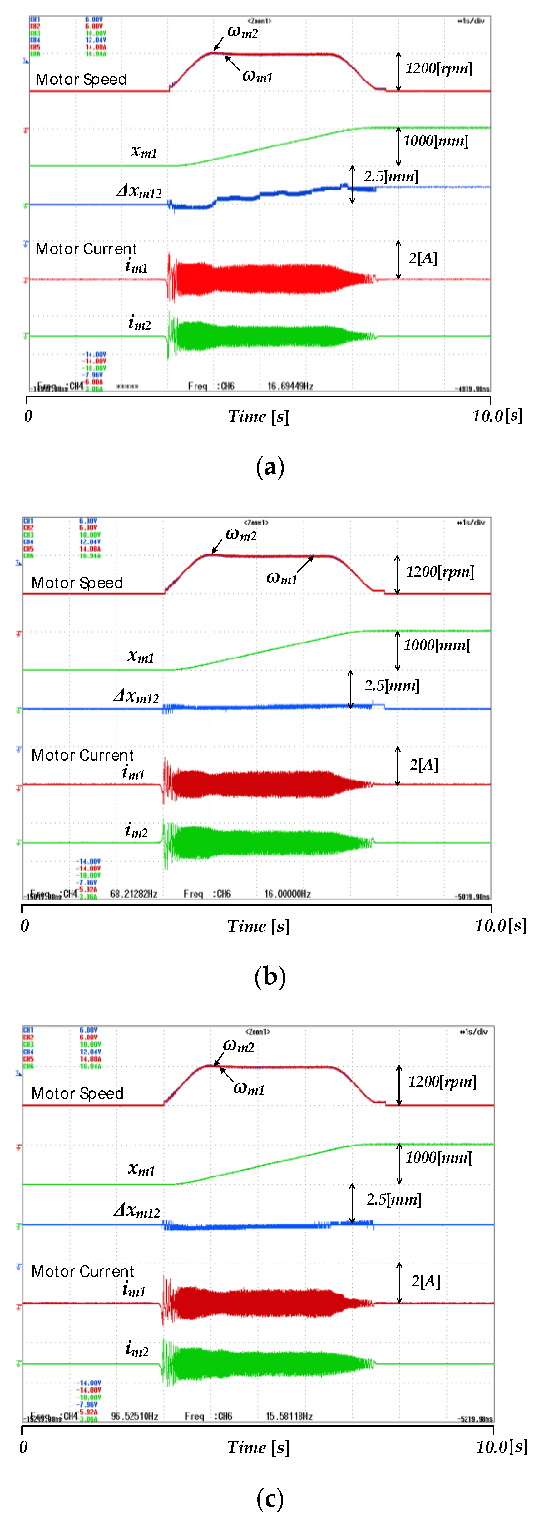
5. Experimental Results
6. Conclusions
Author Contributions
Funding
Institutional Review Board Statement
Informed Consent Statement
Data Availability Statement
Conflicts of Interest
References
- Koivo, A.; Ten-Huei, G. Adaptive Linear Controller for Robotic Manipulators. IEEE Trans. Autom. Control 1983, 28, 162–171. [Google Scholar] [CrossRef]
- Xu, J.; Liu, J.; Sheng, J.; Liu, J. Arc Path Tracking Algorithm of Dual Differential Driving Automated Guided Vehicle. In Proceedings of the 2018 11th International Congress on Image and Signal Processing, BioMedical Engineering and Informatics (CISP-BMEI), Beijing, China, 13–15 October 2018; pp. 1–7. [Google Scholar]
- Barankova, I.; Mikhailova, U.; Lukianov, G. Automated Control System of a Factory Railway Transport Based on ZigBee. In Proceedings of the 2016 2nd International Conference on Industrial Engineering, Applications and Manufacturing (ICIEAM), Chelyabinsk, Russia, 19–20 May 2016; pp. 1–5. [Google Scholar]
- Hossain, S.G.M.; Jamil, H.; Ali, M.Y.; Haq, M.Z. Automated Guided Vehicles for Industrial Logistics—Development of Intelligent Prototypes Using Appropriate Technology. In Proceedings of the 2010 The 2nd International Conference on Computer and Automation Engineering (ICCAE), Singapore, 26–28 February 2010; pp. 237–241. [Google Scholar]
- Yamamoto, S. Development of Inspection Robot for Nuclear Power Plant. In Proceedings of the 1992 IEEE International Conference on Robotics and Automation, Nice, France, 14 May 1992; pp. 1559–1566. [Google Scholar]
- Kim, D.; Lee, S.; Kang, M.; Chun, B.; Han, C. Proposal of Built-in-Guide-Rail Type Building Façade Cleaning Robot and Its Motion Planning Algorithm. In Proceedings of the 2012 IEEE International Conference on Automation Science and Engineering (CASE), Seoul, Korea, 20–24 August 2012; pp. 1004–1009. [Google Scholar]
- Wang, L.; Liu, F.; Xu, S.; Cheng, S.; Zhang, J. Design and Analysis of a Line-Walking Robot for Power Transmission Line Inspection. In Proceedings of the 2010 IEEE International Conference on Information and Automation, Harbin, China, 20–23 June 2010; pp. 1398–1403. [Google Scholar]
- Wang, L.; Liu, F.; Wang, Z.; Xu, S.; Cheng, S.; Zhang, J. Development of a Novel Power Transmission Line Inspection Robot. In Proceedings of the 2010 1st International Conference on Applied Robotics for the Power Industry, Montreal, QC, Canada, 5–7 October 2010; pp. 1–6. [Google Scholar]
- Bae, J.; Lee, D. Position Control of a Rail Guided Mover Using a Low-Cost BLDC Motor. IEEE Trans. Ind. Appl. 2018, 54, 2392–2399. [Google Scholar] [CrossRef]
- Zhakov, A.; Zhu, H.; Siegel, A.; Rank, S.; Schmidt, T.; Fienhold, L.; Hummel, S. Automatic Fault Detection in Rails of Overhead Transport Systems for Semiconductor Fabs. In Proceedings of the 2019 30th Annual SEMI Advanced Semiconductor Manufacturing Conference (ASMC), Saratoga Springs, NY, USA, 6–9 May 2019; pp. 1–6. [Google Scholar]
- Borgerink, D.J.; Stegenga, J.; Brouwer, D.M.; Wörtche, H.J.; Stramigioli, S. Rail-Guided Robotic End-Effector Position Error Due to Rail Compliance and Ship Motion. In Proceedings of the 2014 IEEE/RSJ International Conference on Intelligent Robots and Systems, Chicago, IL, USA, 14–18 September 2014; pp. 3463–3468. [Google Scholar]
- Viegas, C.; Tavakoli, M.; Lopes, P.; Dessi, R.; de Almeida, A.T. SCALA—A Scalable Rail-Based Multirobot System for Large Space Automation: Design and Development. IEEE/ASME Trans. Mechatron. 2017, 22, 2208–2217. [Google Scholar] [CrossRef]
- Cupertino, F.; Naso, D.; Mininno, E.; Turchiano, B. Sliding Mode Control with Double Boundary Layer for Robust Compensation of Payload Mass and Friction in Linear Motors. In Proceedings of the 2008 IEEE Industry Applications Society Annual Meeting, Portland, OR, USA, 5–9 October 2008; pp. 1–8. [Google Scholar]
- Liu, X.; Cao, H.; Wei, W.; Wu, J.; Li, B.; Huang, Y. A Practical Precision Control Method Base on Linear Extended State Observer and Friction Feedforward of Permanent Magnet Linear Synchronous Motor. IEEE Access 2020, 8, 68226–68238. [Google Scholar] [CrossRef]
- Zhao, J.; Jiang, X.; Cheng, W.; Zhao, J.; Wang, H.; Gong, K. Precise Position Detection of Linear Motor Movers Based on Extended Joint Transformation Correlation. IEEE Trans. Ind. Inform. 2020, 16, 814–822. [Google Scholar] [CrossRef]
- Chen, D.; Yin, J.; Chen, L.; Xu, H. Parallel Control and Management for High-Speed Maglev Systems. IEEE Trans. Intell. Transp. Syst. 2017, 18, 431–440. [Google Scholar] [CrossRef]
- Zhou, H.; Deng, H.; Duan, J. Hybrid Fuzzy Decoupling Control for a Precision Maglev Motion System. IEEE/ASME Trans. Mechatron. 2018, 23, 389–401. [Google Scholar] [CrossRef]
- Smoczek, J.; Szpytko, J. Particle Swarm Optimization-Based Multivariable Generalized Predictive Control for an Overhead Crane. IEEE/ASME Trans. Mechatron. 2017, 22, 258–268. [Google Scholar] [CrossRef]
- Sun, N.; Yang, T.; Fang, Y.; Wu, Y.; Chen, H. Transportation Control of Double-Pendulum Cranes with a Nonlinear Quasi-PID Scheme: Design and Experiments. IEEE Trans. Syst. ManCybern. Syst. 2019, 49, 1408–1418. [Google Scholar] [CrossRef]
- Xing, X.; Liu, J. PDE Modelling and Vibration Control of Overhead Crane Bridge with Unknown Control Directions and Parametric Uncertainties. IET Control Theory Appl. 2019, 14, 116–126. [Google Scholar] [CrossRef]
- Tomizuka, M.; Hu, J.-S.; Chiu, G.; Kamano, T. Synchronization of Two Motion Control Axes Under Adaptive Feedforward Control. J. Dyn. Syst. Meas. Control Trans. 1992, 114, 196–203. [Google Scholar] [CrossRef]
- Alain, B.; Maria, P.-D.; Phillipe, D.; Rosendo, P.-E.; Paul-Etienne, V.; Xavier, K. Weighted Control of Traction Drives with Parallel-Connected AC Machines. IEEE Trans. Ind. Electron. 2006, 53, 1799–1806. [Google Scholar]
- Sven, G.R.; Lorenz, H.; Sameer, K.; Klas, N. Precise Robot Motions using Dual Motor Control. In Proceedings of the 2010 IEEE International Conference on Robotics and Automation, Anchorage, AK, USA, 3–8 May 2010; pp. 5613–5620. [Google Scholar]
- Xiao, Y.; Zhu, K.Y. Optimal Synchronization Control of High-precision Motion System. IEEE Trans. Ind. Electron. 2006, 53, 1160–1169. [Google Scholar] [CrossRef]
- Wei, C.; Yifei, W.; Renhui, D.; Qingwei, C.; Xiaobei, W. Speed Tracking and Synchronization of a Dual-Motor System via Second Order Sliding Mode Control. Math. Probl. Eng. 2013, 2013, 1–10. [Google Scholar]
- Mikho, M. Control of Dual-Motor Drive Systems. In Proceedings of the International Conference on Mechatronics and Information Technology 2001, Como, Italy, 8–12 July 2001; pp. 1–6. [Google Scholar]


| Parameter | Value | Parameter | Value |
|---|---|---|---|
| Gear Ratio | 26:1 | Total Length | 533.2 mm |
| Total Height | 510.2 mm | Width | 233.2 mm |
| Upside Height | 258.6 mm | Inside Width | 183.2 mm |
| Rail Width | 160.0 mm | Rail Height | 80.0 mm |
| Parameter | Value | Parameter | Value |
|---|---|---|---|
| Power | 180 W | Voltage | 24 V |
| Rated Current | 7 A | Rated Speed | 4200 r/min |
| Phase Resistance | 0.0894 Ω | Phase Inductance | 0.122 mH |
| Pole-pair | 8 | Tire Radius | 115 mm |
Publisher’s Note: MDPI stays neutral with regard to jurisdictional claims in published maps and institutional affiliations. |
© 2021 by the authors. Licensee MDPI, Basel, Switzerland. This article is an open access article distributed under the terms and conditions of the Creative Commons Attribution (CC BY) license (http://creativecommons.org/licenses/by/4.0/).
Share and Cite
Cho, K.; Lee, D.-H. Design and Position Control of Overhang-Type Rail Mover Using Dual BLAC Motor. Energies 2021, 14, 1000. https://doi.org/10.3390/en14041000
Cho K, Lee D-H. Design and Position Control of Overhang-Type Rail Mover Using Dual BLAC Motor. Energies. 2021; 14(4):1000. https://doi.org/10.3390/en14041000
Chicago/Turabian StyleCho, Kiwan, and Dong-Hee Lee. 2021. "Design and Position Control of Overhang-Type Rail Mover Using Dual BLAC Motor" Energies 14, no. 4: 1000. https://doi.org/10.3390/en14041000
APA StyleCho, K., & Lee, D.-H. (2021). Design and Position Control of Overhang-Type Rail Mover Using Dual BLAC Motor. Energies, 14(4), 1000. https://doi.org/10.3390/en14041000