1. Introduction
With large-scale distributed power and diverse load growth, power systems have become increasingly complex and large in capacity. Therefore, power systems can be connected to systems such as alternating current (AC) traction systems and electrical arc furnaces. These systems can have negative effects on power quality, such as phase imbalances, low power factor and harmonic distortion. Because the power quality problems adversely affect other electric facilities sharing the same line with these systems that cause power quality problems, technology is needed to improve power quality and stabilize the complex power system by eliminating these issues [
1,
2,
3,
4,
5,
6]. The flexible AC transmission system (FACTS) is a representative technology for improving power quality. The FACTS is a power transmission facility using semiconductor devices that enables large capacity power transmission and ensures the stability of power system. FACTS facilities are divided into two main categories: series-connected and shunt-connected configurations [
5,
6,
7,
8]. Among them, voltage source converter (VSC)-based static synchronous compensators (STATCOMs) and static VAR compensators (SVCs) are representative shunt-connected FACTS facilities. Due to the large capacity of a thyristor, SVCs based on thyristors are mainly used in large capacity power transmission systems. On the other hand, VSC-STATCOMs have advantages such as high control flexibility, fast response speed and low harmonic distortion of output current, thanks to the fast switching frequency and forced commutation feature of power switches such as insulated gate bipolar transistor (IGBT) and integrated gate commutated thyristor (IGCT). Although the VSC-STATCOM is more expensive than the SVC, these aforementioned advantages have led to the increasing use of VSC-STATCOMs over SVCs. VSC-STATCOMs can supply reactive power to improve power quality, compensate for disturbance and stabilize complex power systems. Two-level VSCs have been used in conventional STATCOMs. In a large capacity power system, the two-level VSC-STATCOM requires a bulk coupling transformer, and a filter should be added to the system according to conditions. However, by applying multilevel VSC-high voltage direct current (HVDC) composed of numerous voltage levels to the STATCOM, it is easy to increase voltage level and rated power and significantly reduce the size of the coupling transformer and filter. Due to these benefits, multilevel converters are increasingly being applied to VSC-STATCOMs. Among these multilevel converters, the cascaded H-bridge (CHB) converter is the most representative and suitable topology for the VSC-STATCOM. The CHB converter consists of numerous cells, which can be formed by an H-bridge converter with a DC capacitor. Due to the series-connected cells in the CHB converter, this topology presents many advantages such as high quality output, simple voltage scaling, fast response, easy packaging and redundancy in case of cell failure [
9,
10,
11,
12].
However, submodule cell capacitor voltage balancing control is necessary to operate the CHB converter because this topology is composed of numerous submodule cells with DC capacitor voltage instantaneously fluctuating depending on the operation sequence of the CHB converter. The submodule capacitor voltage should be balanced to properly compensate reactive power or regulate voltage at the point of common coupling (PCC) under unbalanced grid and load conditions as well as in a stable system. Therefore, many methods for submodule cell capacitor energy balancing have been studied under unbalanced grid and load conditions as well as in stable systems [
13,
14,
15,
16,
17,
18,
19,
20,
21,
22]. Typically, the delta-connected CHB converter uses a zero-sequence circulation current for DC capacitor voltage balancing and leg energy balancing. On the other hand, the wye-connected STATCOM uses a zero-sequence voltage for leg energy balancing because the wye-connected CHB converter does not have the zero-sequence circulation current path and can inject the zero-sequence voltage.
In this paper, a novel control strategy is presented for the wye-connected CHB-converter-based STATCOM. This control strategy is a dual concept of the control strategy for the delta-connected CHB-converter-based STATCOM in the previous study [
23]. The proposed control strategy can balance the three-phase leg energies and was verified both under unbalanced grid and load conditions. The proposed control strategy includes a proposed calculation method for the feedforward term to improve dynamics of balancing control. In general, the balancing controller, which consists of feedback control and feedforward term, can improve dynamic performance over a single feedback-based balancing controller. The controller with a feedforward term is able to mitigate the adverse effects from the measurable disturbances and has better performance over the controller with feedback control alone. The proposed feedforward calculation method uses instantaneous leg output phase voltages and currents to directly calculate zero-sequence voltage for leg energy balancing in the system, and this computational process can be accomplished with the help of an embedded system such as a digital signal processor (DSP). The proposed method can be utilized by system designers to make detailed decisions about overall system design such as the number of submodules, leg inductance and voltage rating of the power semiconductor. This paper includes mathematical vector analysis to demonstrate the validity of the proposed feedforward calculation method. A 50MVA full-scale powersim (PSIM) simulation was used to verify the proposed method.
3. Configuration of Overall Control for CHB–STATCOM
The comprehensive control block diagram of the CHB converter is presented in
Figure 2a. The overall controller is composed of four parts, namely total energy controller, current controller, leg balancing controller and leg voltage modulation parts. In this study, the active current and reactive current were aligned to the positive-sequence
q-axis and
d-axis in a synchronous reference frame, respectively. The total energy controller is the most simple and fundamental controller, as shown in
Figure 2b. In this study, to simplify the configuration of the controller, the
α- and
β-axis current expressed in a space phasor domain in the Cartesian coordinate system were used as input of the current controller, and a fundamental proportional resonance (PR) controller was utilized to regulate the output current as shown in
Figure 2d. A second order generalized integrator (SOGI) and phase locked loop (PLL) were used for extracting the phase angle of the positive sequence of the grid voltage. The total energy controller utilizes the positive-sequence
q-axis current to regulate total energy of the CHB converter. On the other hand, the required reactive power is provided by utilizing the positive-sequence
d-axis current. In addition, the negative-sequence
d- and
q-axis currents are controlled to provide reactive power under unbalanced grid and load conditions.
The total three-phase leg energy of the CHB converter is regulated by controlling the coupled AC grid-side active power as shown in the total energy controller of
Figure 2b. However, to regulate leg energy of each phase as its rated value, an additional controller is required to balance the three-phase legs. The zero-sequence voltage can be injected for leg energy balancing in the wye-connected CHB converter. Therefore, the leg capacitor energy balancing controller utilizes zero-sequence voltage for leg energy balancing as shown in
Figure 2c. The principle of a leg balancing controller in this study is similar to that of References [
15,
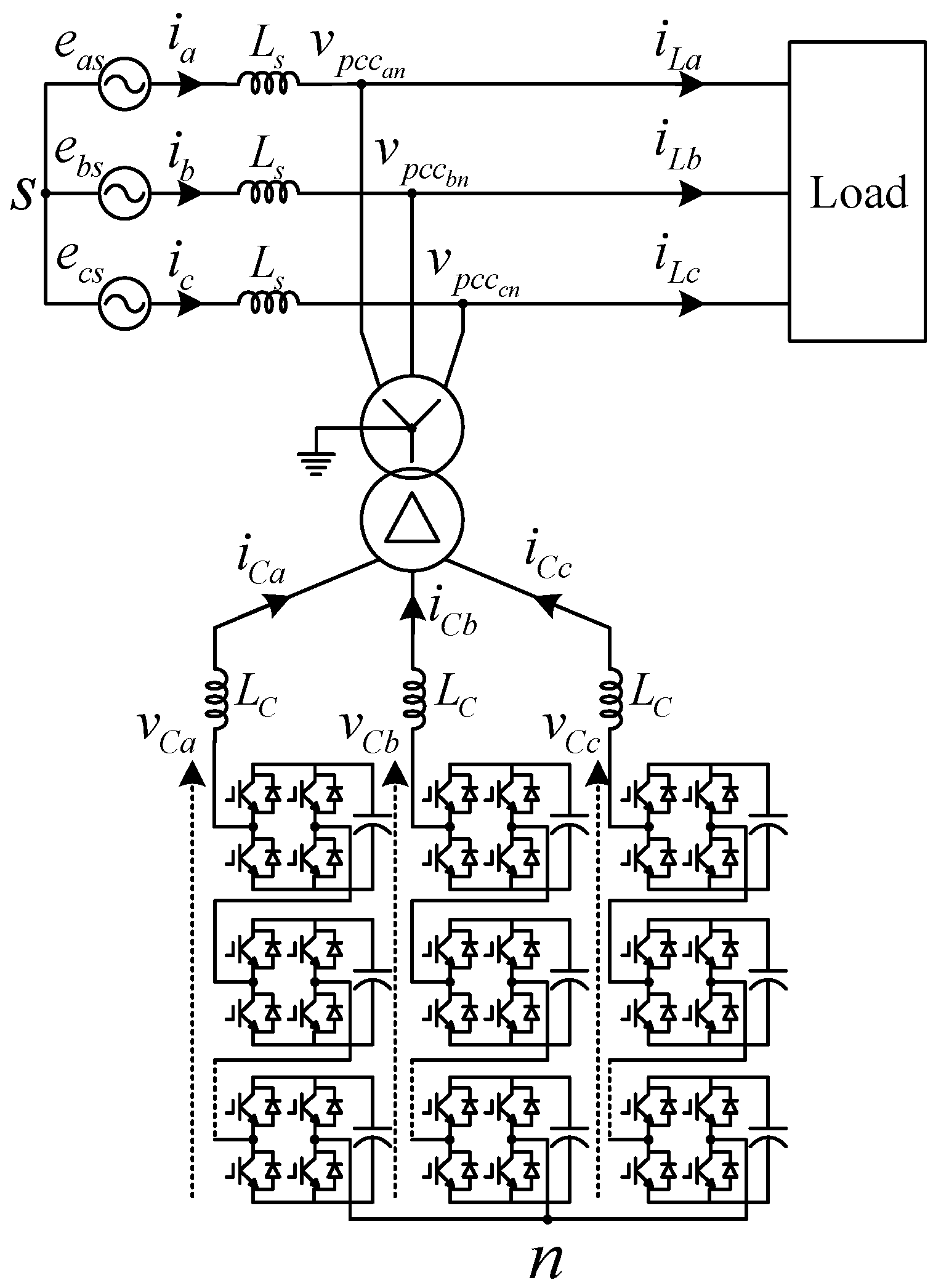
22]. As shown in
Figure 1,
and
stand for leg voltage and leg current, respectively, where
denotes one of the
,
and
phases. The leg voltage and current of the CHB-converter-based STATCOM contain positive- and negative-sequence components. Furthermore, the wye-connected CHB converter has a zero-sequence voltage
. Therefore, the leg voltage and current can be defined as (1) and (2), respectively.
,
,
and
represent the amplitude of positive- and negative-sequence leg voltage and current, respectively.
stands for the amplitude of zero-sequence voltage. The positive-sequence leg voltage is aligned to the
q-axis of the synchronous reference frame.
,
,
and
stand for the phase angles with regard to the
q-axis of the reference frame, respectively.
represents the fundamental frequency of grid voltage. The three-phase voltages have the same zero-sequence voltage as shown in (1). The components, causing the imbalance of three-phase legs, can be compensated by the average active power generated by the zero-sequence voltage and three-phase leg currents. This average active power can be described in the synchronous reference frame as well as in the stationary reference frame as (3).
Equation (3) is also able to be expressed in matrix form as (4).
Therefore, the reference of the zero-sequence voltage can be calculated as (5), where the determinant
D is calculated as (6).
From (5), the reference of instantaneous zero-sequence voltage can be calculated as (7).
This leg energy balancing controller can only include the feedback control. However, in general, most controllers include a feedforward term to improve the control dynamics. Therefore, to improve the dynamics of leg energy balancing control, this paper suggests a feedforward calculation method in
Section 4.
4. Proposed Method of Deriving Zero-Sequence Voltage Vector for Leg Balance
In general, STATCOM provides either inductive or capacitive reactive power. Therefore, the positive-sequence leg voltage vector and leg current vector are positioned vertically, and likewise, the negative-sequence leg voltage vector and leg current vector are also vertical as shown in
Figure 3a,b. In
Figure 3a,
stands for the leg voltage phasor without zero-sequence component, such as (8), where
denotes one of the
,
and
phases.
The leg voltage phasor projected perpendicular onto the leg current phasor is a component that generates active power. These direct components of voltage phasor for the generation of active power are described as
,
and
in
Figure 3c. Assuming the STATCOM provides only reactive power in general, positive-sequence leg voltage vector and positive-sequence leg current vector are orthogonal to each other, and the negative-sequence leg voltage vector and negative-sequence leg current vector are also orthogonal, the inner products of voltage and current vector become zero. Therefore, the direct components of
,
and
can be derived as (9).
In general, under balanced grid and load conditions, the active power of STATCOM used for total energy control of STATCOM is significantly lower than the system rating, and the magnitudes of three-phase active powers are identical. However, the magnitudes between three-phase active powers are different under grid and load imbalance conditions as shown in
Figure 3c. Consequently, this difference of average active power of each phase seriously aggravates the overall balance of system and has negative effects on the normal operation. Therefore, eliminating this difference of three-phase average active powers is very important to maintain stable operation and system balance. Furthermore, the zero-sequence voltage reference should be accurately calculated because it is used to eliminate the imbalance between three-phase average active powers.
In this study, the zero-sequence voltage was calculated using the vector analysis method. This method is a dual concept of the control strategy for a delta-connected CHB-converter-based STATCOM in a previous study [
23]. As shown in
Figure 3d, the direct components of the leg voltage vector can construct a triangle. The circumcenter is the point where the vertical bisectors of three sides of a triangle intersect and is at the same distance from each vertex. The circumcenter is the center of triangle’s circumcircle. The circumcenter vector is described as
in
Figure 3d. The zero-sequence voltage vector,
can be calculated by the circumcenter vector. As (10), the magnitude of zero-sequence voltage vector is twice that of the circumcenter vector and is in the opposite direction of the circumcenter vector at the origin.
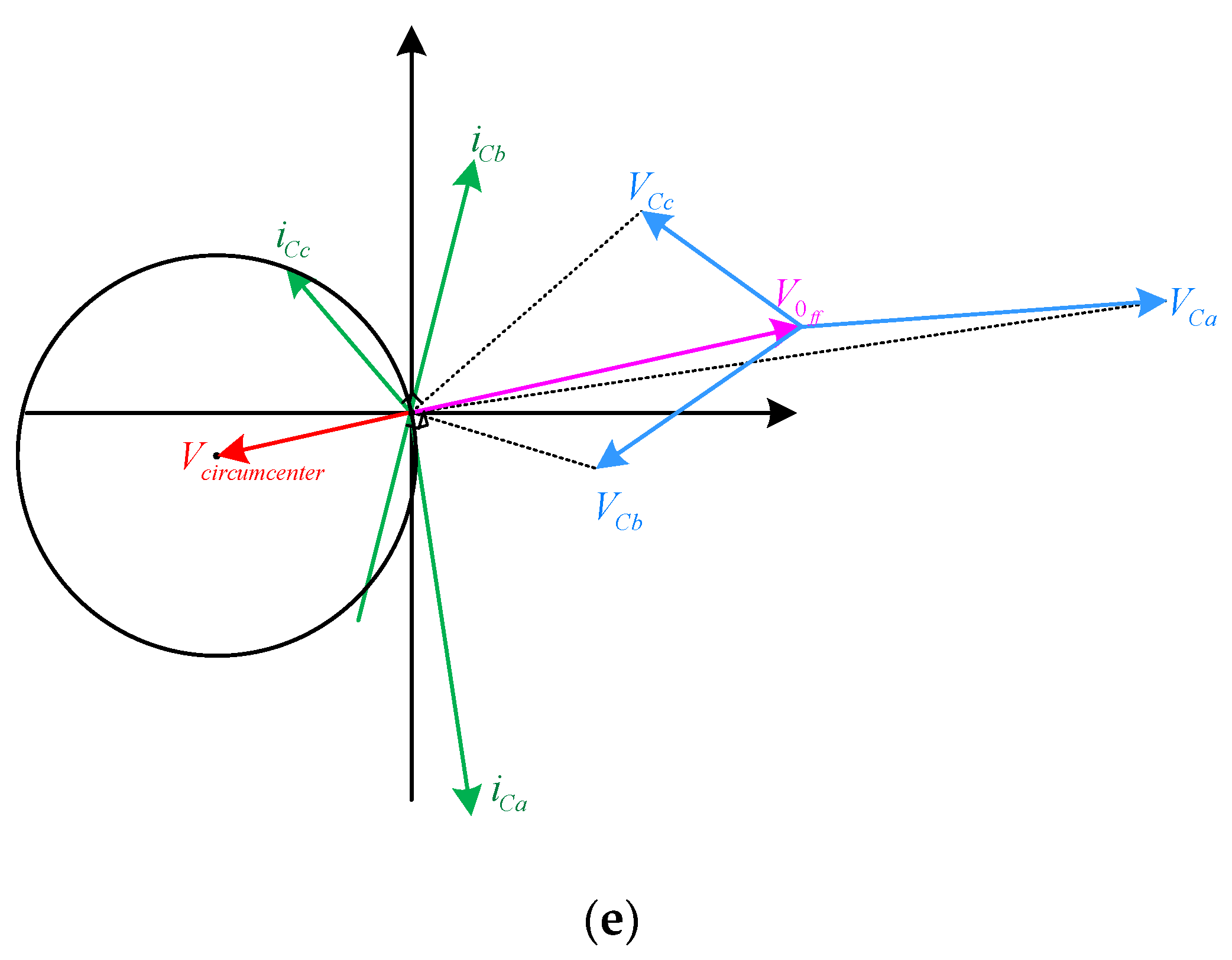
The zero-sequence voltage is injected to compensate for the imbalance of three-phase average active powers as shown in
Figure 3e. As a result, if the direct component vectors of the leg voltage phasor are projected perpendicular onto the leg current vector and become zero, the imbalance of three-phase average active powers can be eliminated with the zero-sequence voltage. Therefore, the zero-sequence voltage vector calculated by circumcenter vector can be used as the feedforward term.
5. Mathematical Description of Validation of the Proposed Method
In
Section 4, the feedforward calculation method for leg energy balancing is proposed. In addition, the proposed method is described mathematically in this section. Because of the verticality between the leg voltage vector with zero-sequence voltage and the leg current vector, the proposed method is valid if the inner product of the leg voltage vector with zero-sequence voltage and the leg current vector becomes zero as (11).
Assuming the STATCOM provides only reactive power, the positive-sequence leg voltage vector and leg current vector are vertical, and likewise, the negative-sequence leg voltage vector and leg current vector are also vertical, as (12), where
denotes one of the
,
and
phases.
Therefore, the inner product of positive- and negative-sequence leg voltage vector and leg current vector becomes zero as (13).
As a result, (11) can be defined as (14).
The last term of (14) shows that the zero-sequence voltage compensates for unbalanced leg power. There are two processes used in order to demonstrate (14). First, (14) is demonstrated using the projection vector and assumption that the triangle’s circumcircle passes the origin. This assumption is proven in the following subsections.
5.1. Mathematical Description Using the Projection Vector and Assumption
First, the direct component vector of leg voltage,
can be defined by the principle of projection vector as (15), where
means magnitude of a vector.
Next, considering the assumption that the circumcircle of the triangle constructed from three direct component vectors passes the origin, (16) is described by the feature that the circumcenter is the center of triangle’s circumcircle.
Then, (17) is derived according to (10), (15) and (16).
Finally, (14) is derived by (17). Therefore, the zero-sequence voltage calculated by the proposed method can exactly compensate for unbalanced leg power as in
Figure 3c.
5.2. Verification of the Assumption
In order for the previous proof to be valid, the circumcircle of the triangle made up of three direct component vectors should pass the origin. Because the circle that passes through three different vectors is only one, the circle on three different points (
,
,
) that passes through the origin is equal to the circle on three different points (
,
,
) including the origin that passes through. Therefore, proving that the circle on three different points (
,
,
) passes through
is equal to proving the assumption that the circumcircle of the triangle constructed from three direct component vectors passes the origin. Considering three different vectors including the origin vector, two direct component vectors are described as (18).
From (17), (18) can be rewritten as (19).
The sum of two equations in (19) is
Assuming the STATCOM system provides only reactive power to the PCC, the sum of the inner product of the three-phase voltage and current vectors should be zero as (21).
(20) can be rewritten as (22) using (21).
Then, the sum of leg current vectors is zero as (23).
Finally, (22) is derived as (24) using (17) and (23).
The last equation in (24) satisfies (16). In other words, the circumcircle of the triangle constructed from three direct component vectors passes the origin. As a result, the assumption is proven, and the previous proof using the projection vector and the assumption is also valid.
6. Full-Scale Wye-Connected CHB–STATCOM System Simulation Results
A 50 MVA full-scale CHB–STATCOM simulation was performed using the PSIM program to verify the proposed feedforward method. The overall simulation configuration is basically same as in
Figure 1, and simulation parameters are shown in
Table 1. The parameters of the 10 MVA full-scale STATCOM simulation were modified and employed according to Reference [
16]. The rated power of the converter was set to 50 MVA, and the rated output line-to-line rms voltage was 10 kV. The rated DC average voltage of each cell was set as 1326 V considering the specification of commercial press pack IGBT or IGCT and their voltage margin. To secure the output voltage margin for synthesized leg output voltage and superimposed zero-sequence voltage for leg balancing, the number of submodule cells in each leg was determined as 10. Furthermore, the detailed rationale for determining the capacitance of cell capacitor and inductance of interface inductor in
Table 1 is described in
Appendix A and
Appendix B, respectively.
Since the proposed feedforward method considers the positive- and negative-voltage and current for a seamless transition, the proposed feedforward method can operate normally under unbalanced grid and load conditions. Therefore, the simulation was performed under both unbalanced grid and load conditions.
6.1. The Load Imbalance Condition
To emulate unbalanced load conditions, the inductance of
-phase load was intentionally increased to three times. As shown in
Figure 4 and
Figure 5, the inductance of
-phase load is abruptly increased to three times at the time point of 1.2 s. During the period of load imbalance, the load current is unbalanced. The load imbalance is cleared at the time point of 1.6s. During the load imbalance circumstance, the CHB–STATCOM provides unbalanced load current to compensate and eliminate unbalanced grid current as shown in
Figure 4a and
Figure 5a. The zero-sequence voltage is injected into each leg to balance the leg energy.
Figure 4 shows the simulation waveforms when the feedforward term is not applied, and
Figure 5 shows the waveforms when the proposed feedforward is applied. As shown in
Figure 4d and
Figure 5d, the peak values of DC capacitor voltages of
Figure 4d are much larger than those of
Figure 5d. At the beginning and the end point of load imbalance, the peak values of DC capacitor voltages when the feedforward is not applied is about 8 percent greater than the rated voltage of DC capacitor voltages. However, the peak values of DC capacitor voltages when the proposed feedforward is applied are about 4.0 and 2.5 percent greater than the rated voltage of the DC capacitor voltages at the beginning and the end point of load imbalance, respectively.
Figure 6 shows zero-sequence voltage output from the feedback controller excluding the proposed feedforward term, and the calculated feedforward term from the proposed method is also drawn in overlapping ways. As shown in
Figure 6, the calculated feedforward term from the proposed method is equal to the zero-sequence voltage of the leg energy balancing feedback controller without the feedforward term in steady state. Therefore, the proposed feedforward method is valid under unbalanced load conditions.
6.2. The Grid Imbalance Condition (SLG Fault)
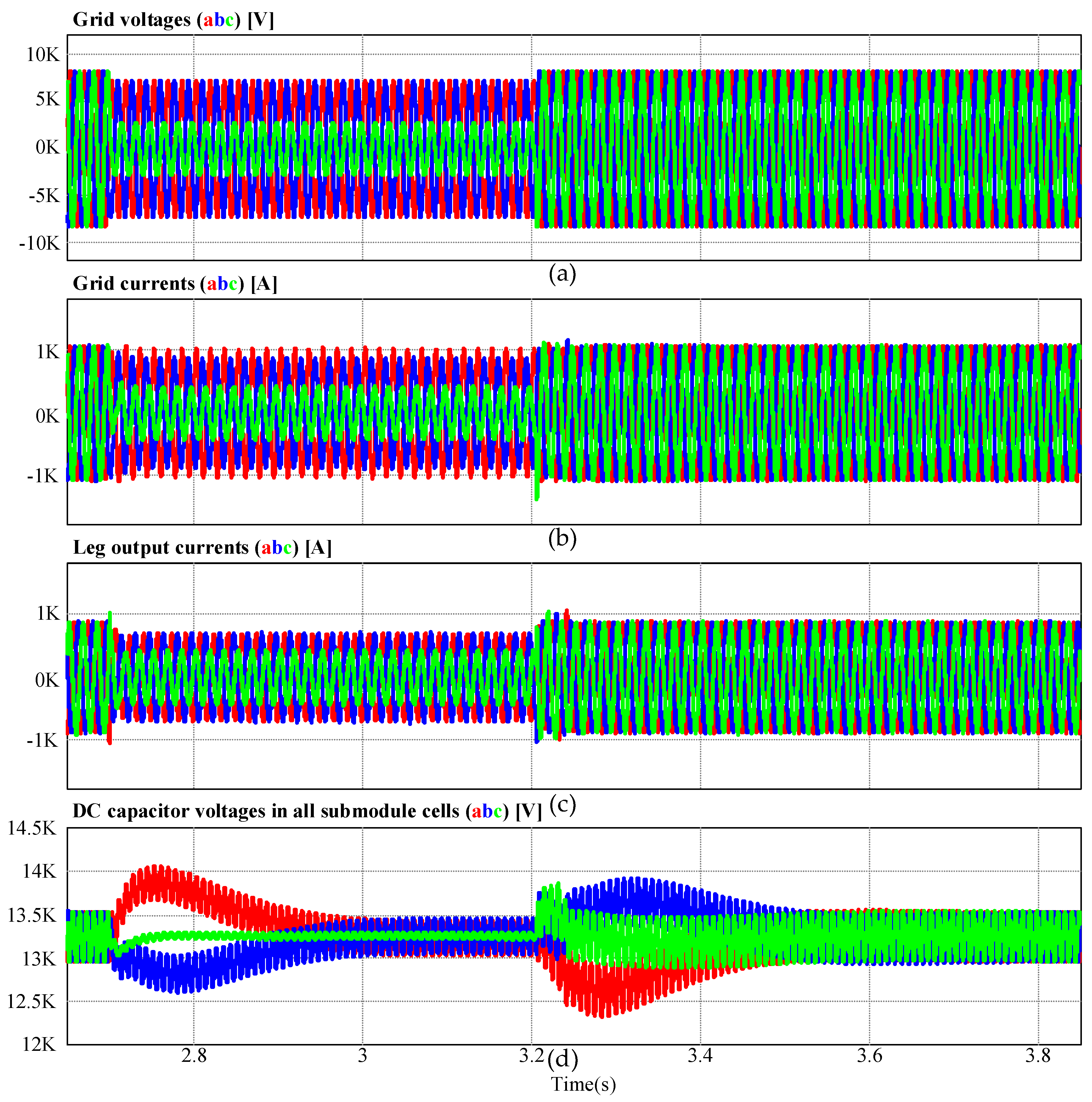
The proposed feedforward calculation method was verified under unbalanced grid conditions by simulating a single-line-to-ground (SLG) fault. As shown in
Figure 7 and
Figure 8, SLG fault occurs at the time point of 2.7 s. During the period of SLG fault, leg output currents and voltages are unbalanced. Therefore, the zero-sequence voltage is injected into each leg to balance the leg energy.
Figure 7 and
Figure 8 show the simulation waveforms when the feedforward term is not included and the feedforward is applied, respectively. As shown in
Figure 7d and
Figure 8d, the peak values of DC capacitor voltages of
Figure 7d are much larger than those of
Figure 8d. At the beginning and the end point of SLG fault, the peak values of DC capacitor voltages when the feedforward is not applied are about 6.0 and 5.0 percent greater than the rated voltage of DC capacitor voltages, respectively. However, the peak ripple values of DC capacitor voltages when the feedforward is applied are about 3.0 and 4.0 percent greater than the rated voltage of DC capacitor voltages at the beginning and the end point of load imbalance, respectively. To validate the proposed method,
Figure 9 presents zero-sequence voltage output from the feedback controller without the feedforward term, and the proposed calculated feedforward term is intentionally drawn in overlapping ways. As shown in
Figure 9, the calculated feedforward term from the proposed method is equal to the zero-sequence voltage of the leg balancing feedback controller without the feedforward term in steady state. Therefore, the proposed feedforward method is valid under unbalanced grid conditions.
As shown by the simulation results, the proposed feedforward method is effective and reliable under both unbalanced grid and load conditions. When the proposed feedforward term is applied, the peak values of DC capacitor voltages can be reduced, and the dynamics of the leg energy balancing controller can be improved. Therefore, the stability of the CHB–STATCOM system can be improved.


