Article

Controllable-Dual Bridge Fault Current Limiter for Interconnection Micro-Grids

by
Hossein Shahbabaei Kartijkolaie
1,
Kuo-Hsien Hsia
2,
Saleh Mobayen
3,*,
Mehdi Firouzi
4,* and
Mohammadreza Shafiee
5
1
Golestan Provinace Distribution Electrical Company, Gorgan 517212, Iran
2
Bachelor Program in Interdisciplinary Studies, National Yunlin University of Science and Technology, 123 University Road, Section 3, Douliou, Yunlin 64002, Taiwan
3
Future Technology Research Center, National Yunlin University of Science and Technology, 123 University Road, Section 3, Douliou, Yunlin 64002, Taiwan
4
Department of Electrical Engineering, Abhar Branch, Islamic Azad University, Abhar 1584743311, Iran
5
Department of Electrical and Computer Engineering, University of Semnan, Semnan 3535168641, Iran
*
Authors to whom correspondence should be addressed.
Energies 2021, 14(4), 1026; https://doi.org/10.3390/en14041026
Submission received: 11 January 2021 / Revised: 31 January 2021 / Accepted: 9 February 2021 / Published: 16 February 2021

Abstract

:
Different types of fault current limiters (FCLs) have been developed and designed based on non-superconducting DC reactors (NSDRs). This paper proposes a controllable dual-bridge FCL (CDBFCL) based on the NSDR for use in an AC-type micro-grid. It includes a NSDR and two series and shunt bridge circuits. The series bridge is based on diode semiconductor switches and is coupled in series with the line via a transformer. The shunt bridge is based on thyristor semiconductor switches and is coupled in parallel with the line. The shunt bridge provides a variable voltage source. It compensates for the DC side voltage drop due to NSDR resistance and semiconductor switches during normal operating condition. In addition, by controlling the shunt bridge firing angle, it produces a controllable DC voltage, which can control the fault current amplitude during a fault. The structure, principle operating work, and control system of the proposed CDBFCL are presented. The CDBFCL performance is studied analytically and through simulation by the PSCAD/EMTDC software. In addition, the simulation results are compared with those obtained experimentally from a prototype CDBFCL and show a close correlation.

1. Introduction

Due to the increasing penetration level of distributed generation (DG) systems in modern distribution systems, the concept of micro-grids (MGs) has emerged as a safe and reliable control method of DG systems [1]. The increasing short-circuit current is one of the main challenges of the expansion and development of MGs. The integration of new DGSs is the main cause of increasing short-circuit currents in the grid-connected mode of MGs [1,2]. This imposes high electromechanical stress and can cause insulation failure, over-voltage transients, and the explosion of existing MG equipment, which can threaten the safe and reliable operation of MG under fault conditions [3]. To cope with these challenges, the grid operators need to upgrade the MG equipment or modify the MG configuration. Grid reconfiguration such as bus splitting may lead to lower reliability and security [3,4]. However, the replacement of equipment incurs higher capital cost. Fault current limiters (FCLs) are potential alternatives to the mentioned approaches to reduce the fault current in MGs [4]. They can limit the short-circuit current without changes in MG configuration at a predefined level in the shortest possible time. They also have no influence on normal operation of the grid [5,6].
Different types of FCL have been developed in recent years, which are classified into superconducting-type FCLs (SFCLs), resonant-type FCLs (RFCLs) and solid state-type FCLs (SSFCLs) [7]. SFCLs are one of the most promising devices for use in MGs, due to their several advantages. They can limit fault current with low power losses, rapid response time, and an automatic response without external control [7,8]. They are equipped with high-temperature superconducting materials and are classified into inductive and resistive types [8]. In [9], the restive-type SFCL was used in isolated MG with a high penetration level of DGs. It was shown that using resistive-type SFCL limits the fault current as well as enhancing the transient stability in islanding mode. In [10], an inductive-type SFCL was used for interconnection between the AC-type MG to the main grid to control the short-circuit current and power flow. In [11], an inductive-type SFCL was used for the integration of the downstream wind-based DG to the main AC grid. In [12], a flux-coupling type SFCL was used to satisfy the fault-rid through (FRT) requirement of double-fed induction-generator (DFIG)-based DG in MG. However, they need high-cost, high-temperature materials and cooling devices [13].
Generally, the RFCLs are composed of a series LC tuned circuit, which is controlled by a metal oxide varistor (MOV), and a parallel LC with a bridge rectifier circuit [14]. In [15], a series-type RFCL with MOV was used for controlling the short-circuit penetration and the FRT capability of a DFIG-base DG unit. In [16], this type of FCL with a solid-state bypass circuit was used to interconnect the MG to the upstream main grid. In [17], a parallel type of RFCLs was used to comply with the FRT requirements of a 2MW DFIG-based DG unit. RFCLs are an extremely urgent and economical type of FCL used to decrease the short circuit current level. However, the employment of them in MGs has serious over-voltage and sub synchronous resonance problems.
Due to the development of semiconductor technologies, several types of fast action SSFCL have been introduced and presented. In addition, some of them have been developed commercially and have become available [18]. The SSFCLs are composed of solid-state semiconductor switches and passive elements such as resistors, inductors, and capacitors in different configurations, which are presented as bridge-type FCLs (BFCLs) [19,20,21].
In recent years, the application of BFCLs was found to be a cost-effective and promising method to manage and control fault currents [20,21]. In the literature, several BFCLs with different configurations have been presented and documented. In [22], a NSDR was implemented in the BFCL power circuit as a limiting impedance for limiting the short-circuit current of a grid with dispersed generators. It limits the transient fault current at the fault-occurring instant without any delay. In addition, it requires any control system. However, it cannot limit the steady-state fault current under fault conditions, which is the weak point of this type of BFCL. To overcome this challenge, the BFCL presented in [22] was modified by using a reverse magnetization core [23]. However, the efficiency of this method is not significant. In [24], the power circuit of BFCL was changed by using additional semiconductor switches and a conventional reactor, which operates in both AC and DC modes. During normal operating conditions, the BFCL converts the AC line current to DC current, which flows through the reactor to reduce the voltage drop. During fault operating conditions, the BFCL configuration is changed, and the AC current flows through the reactor. Therefore, the impedance of the rector limits the fault current amplitude in these operating conditions. However, it requires four controllable semiconductor switches and two non-controllable semiconductor switches for each phase of the BFCL, which leads to a high-cost and -complexity control system. In [25], a discharging resistor was added in series with the DC reactor in the BFCL structure to limit both the transient and steady-state fault current. In [26], the BFCL reported in [25] with a voltage sag compensation function was used to protect the coupling bus voltage by controlling fault current in a distribution system. In [27], multi discharging-resistors were used in the DC side of a BFCL instead of one discharging resistor. This compensates for the voltage sag at the DFIG terminal to enhance the FRT under whole conditions. In addition, this structure without the series transformer is used for connecting the converter-based DG unit to the grid [28]. However, BFCLs require a high current-rating DC reactor and semiconductor switches due to the flowing fault current amplitude from them.
In [29], a shunt three-phase bridge rectifier is added to the BFCL reported in [25], to compensate for the voltage drop due to semiconductor switches and DC reactor in the DC side of the BFCL. However, the shunt bridge rectifier is based on diode semiconductor switches. Therefore, the DC voltage produced by the shunt rectifier is fixed and uncontrollable. It is obvious that the line power and, consequently, the line and DC reactor currents are changed. Thus, the voltage drop in the DC side is varied according to the line power variation, and the shunt bridge rectifier cannot compensate for the DC side voltage drop. In addition, it cannot control the fault current magnitude under fault operating conditions. In [30], the authors presented the preliminary design process of the power transformers.
To address these challenges, this paper proposes a controllable dual-bridge FCL (CDBFCL) based on the NSDR for limiting the fault current in MGs. In addition, it does not require the discharging resistor to control the fault current magnitude during a fault. It includes two series and shunt bridge circuits and a NSDR. The series bridge is based on diode semiconductor switches, which is coupled in series with the line. The shunt bridge is based on thyristor semiconductor switches and is coupled in parallel with the coupling bus, which produces a controllable DC voltage source. It compensates for the DC side voltage drop and controls the fault current magnitude during normal and fault operating conditions, respectively. The proposed CDBFCL is built as a prototype and simulated via PSCAD/EMTDC software (Manitoba Hydro International Ltd., Winnipeg, Canada). The simulation and measurements results are compared to illustrate the effectiveness of the CDBFCL.

2. Proposed SDBFCL

As shown in Figure 1, the proposed CDBFCL consists of series and shunt bridges and a NSDR. The series bridge (D1-D6) is coupled in series with the line through transformers TA, TB, and TC, which have the FCL function. The shunt bridge is coupled in parallel with the FCL connecting bus through a shunt transformer, which has the compensation function. A NSDR is located between series and shunt bridges as a limiting impedance, which is modeled by LD and rD as the inductance and resistance of the NSDR. In the normal operating condition, by controlling the firing angle of the shunt bridge, it acts as a controllable DC voltage source for the compensation of the voltage drop due to the NSDR resistance and semiconductor switches. In this condition, the Vsh is negative and is equal to the voltage drop of the NSDR. As a result, the voltage drops of the NSDR and semiconductor switches are approximately equal to zero. Therefore, the secondary side of the series coupling transformers is short-circuited and the impedance of the series transformers is negligible. Under fault operating conditions, the shunt bridge provides a high controllable DC voltage, which limits the NSDR current, and subsequently the fault line current is controlled.

3. Analysis of the CDBFCL Performance

The electric power circuit illustrated in Figure 2a was selected for analytical study. The load and source impedance are presented by Z L = R L + j ω L L and Z S = R S + j ω L S , respectively. LD and rD are the inductance and resistance of the NSDR, respectively. The turn ratios of transformers are equal to 1. The principle operating work of the proposed CDBFCL is classified into normal and fault operating conditions as follows:

3.1. Normal Operating Condition

Under this operating condition, the firing angles of the shunt bridge are controlled for the compensation of the DC side voltage drop. In this condition, the series bridge diodes are in freewheeling state and the id is divided into two paths, including the LD-rD-D1-D3 path and the LD-rD-D2-D4 path. The equivalent circuit of the proposed CDBFCL is presented in Figure 2b. Considering this figure, Vse = 2VDF. VDF is the forward voltage of diodes. It is assumed that the ripple voltage of shunt bridge is negligible, and the shunt bridge is modeled by a DC voltage source (Vsh). The CDBFCL performance is presented in Figure 3 for both normal and fault operating conditions. Therefore, the current of the NSDR is constant for this condition and the Kirchhoff's Voltage Law (KVL) equation in DC side of the CDBFCL can be written as:
V s h 2 V D F = r d i d
So, id is as follows:
i d = V s h 2 V D F r d
In addition, the line current (iL) is obtained by:
i L t = V m Z s sin ω t φ s
In Equation (3), Req = Rs + RL, Leq = Ls + LL, Z s = R e q 2 + L e q ω 2 and φ s = tan 1 L e q ω R e q .

3.2. Fault Operating Condition

When a fault occurs in the load side at t = t0, the CDBFCL control system changes the firing angle of the shunt bridge to produce the appropriate voltage against Vse to control id and subsequently iL. The KVL equation to obtain id and iL is expressed by the following equation:
V s h V s e = r d i d + L d d i d d t
Solving Equation (4) for id results in the following equation:
i d = V s e V s h r d i 0 e r D L D t t 0
where i0 = iL(t = t0), and iL is expressed by the following equation, approximately:
i L = V s e V s h r d i 0 e r d L d t t 0 V m Z s sin ω t φ
In (6), Leq= Ls, Req = Rs, Z s = R e q 2 + L e q ω 2 and φ s = tan 1 L e q ω R e q and Vse = 2Vm, which represents the DC value of the series bridge circuit voltage.

3.3. CDBFCL Control System

The control systems of the conventional BFCL and the proposed CDBFCL are illustrated in Figure 4 and Figure 5, respectively. The conventional BFCL control system only detects the fault and inserts the limiting impedance in the fault path [26,27]. However, it cannot control the fault current level. As presented in Figure 5, to control the firing angles of shunt bridge thyristors, the difference between the measured SNDR current (id) and its reference level (id_ref) is applied to the current-voltage block. Under both normal and fault operating modes, the SNDR current is applied to the current-voltage block to select an appropriate shunt bridge voltage (Vsh). Based on the output voltage of the current-voltage block, the value of the firing angle of the shunt bridge thyristors is determined to control the NSDR and subsequently the current under fault operating condition.

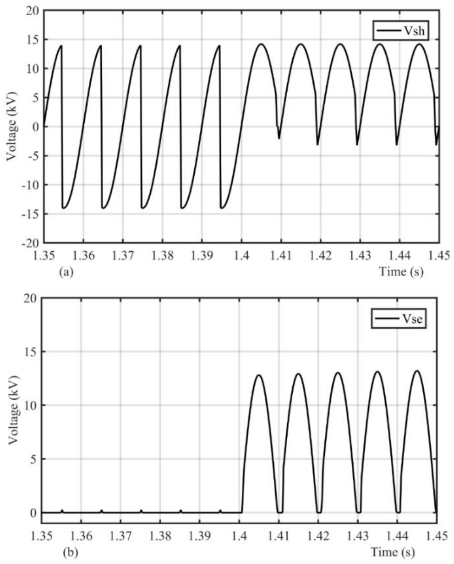
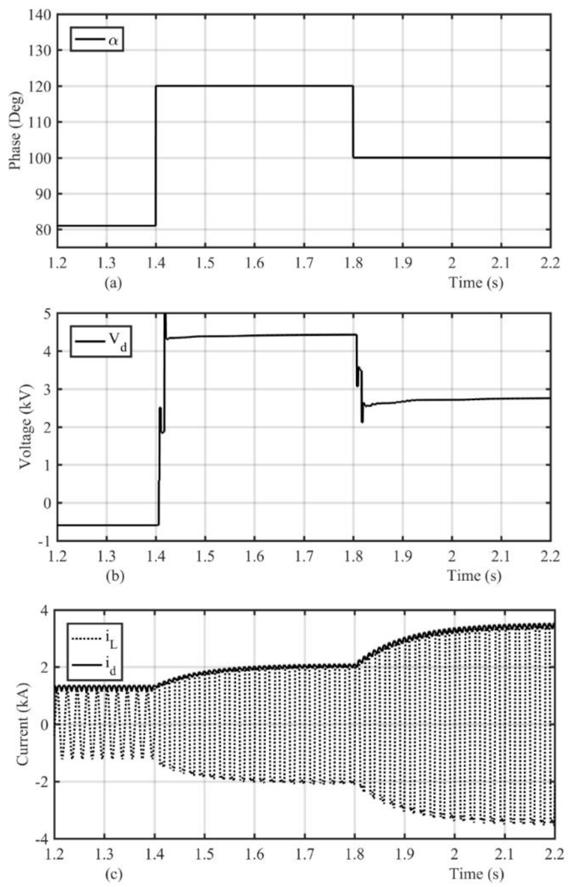
4. Simulation Results

To investigate the efficacy of the proposed CDBFCL, the system shown in Figure 2a was simulated. The parameters of this study system are presented in Table 1. A line to ground (LG) fault was considered and simulated at the terminal of load side, which starts at t = 1.5 s.
Figure 6a demonstrates the characteristics of the fault current for two scenarios including without an FCL and with the proposed FCL. As demonstrated in this figure, the peak value of the fault current is close to 7 kA. However, by using the CDBFCL, the peak value of the fault current is limited to 2 kA. Figure 6b demonstrates the characteristics of the NSDR and fault current under application of the proposed CDBFCL, which are limited to 2 kA. Figure 7a,b demonstrates shunt and series bridge voltages. As demonstrated in Figure 7a, the shunt bridge voltage varies during the fault operating mode to be equal to the series bridge voltage. In addition, the series bridge voltage is equal to zero under the normal operating mode. Figure 8 shows the CDBFCL performance for two firing angles to control the fault current in two levels. Figure 8a demonstrates the firing angle of the bridge circuit thyristors—it is 82 degrees under the normal operating mode. When a fault occurs, it is changed from 120 to 100 degrees. Figure 8b shows the mean value of the shunt bridge voltage—it is −0.6 kV under the normal operating mode. However, it varies from 4.5 to 2.8 kV during a fault. Figure 8c shows the fault current during the fault operating mode. As shown in this figure, the fault current is changed from 2 to 3.8 kA by controlling the firing angle of the shunt bridge during the fault.

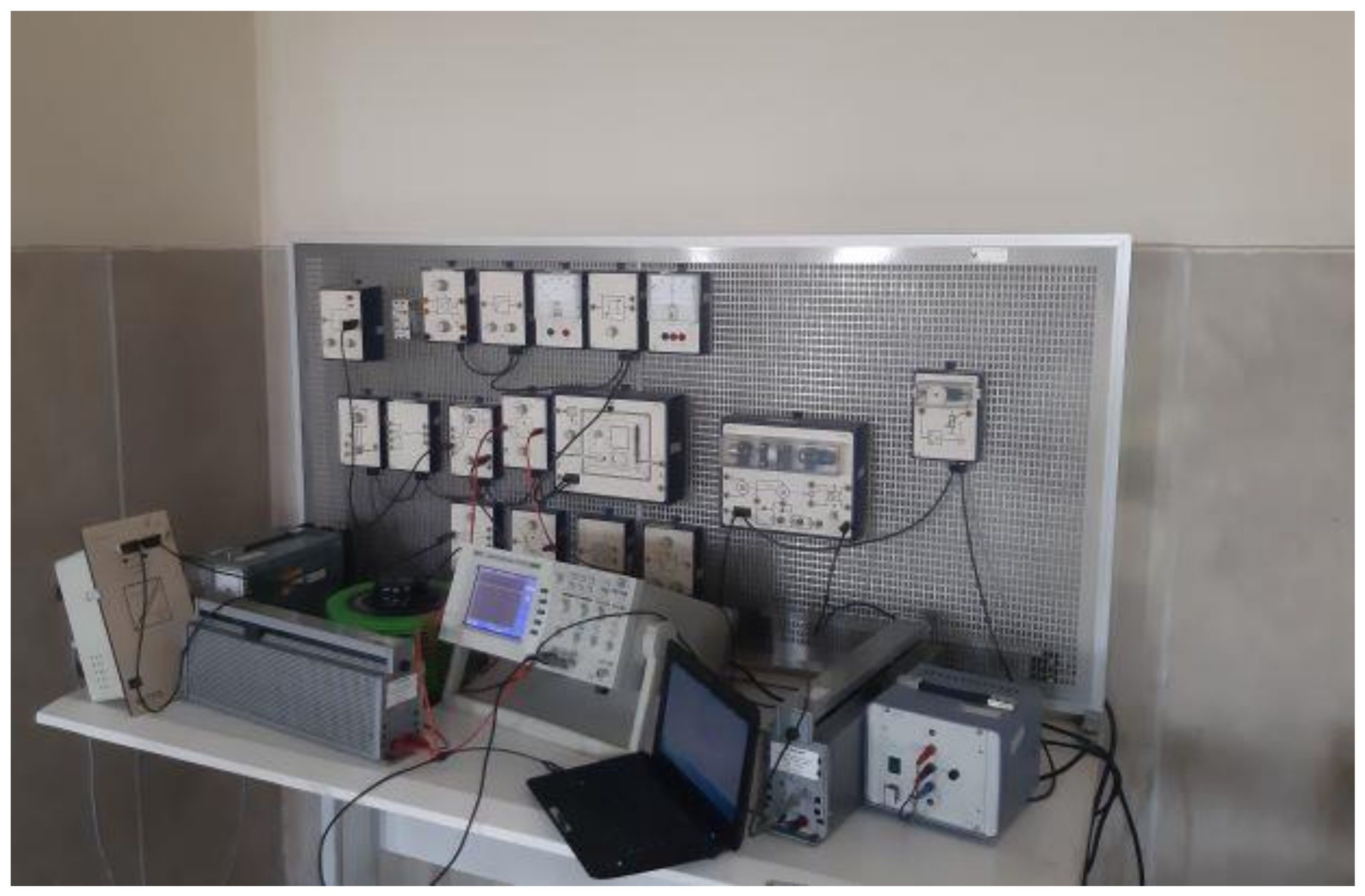
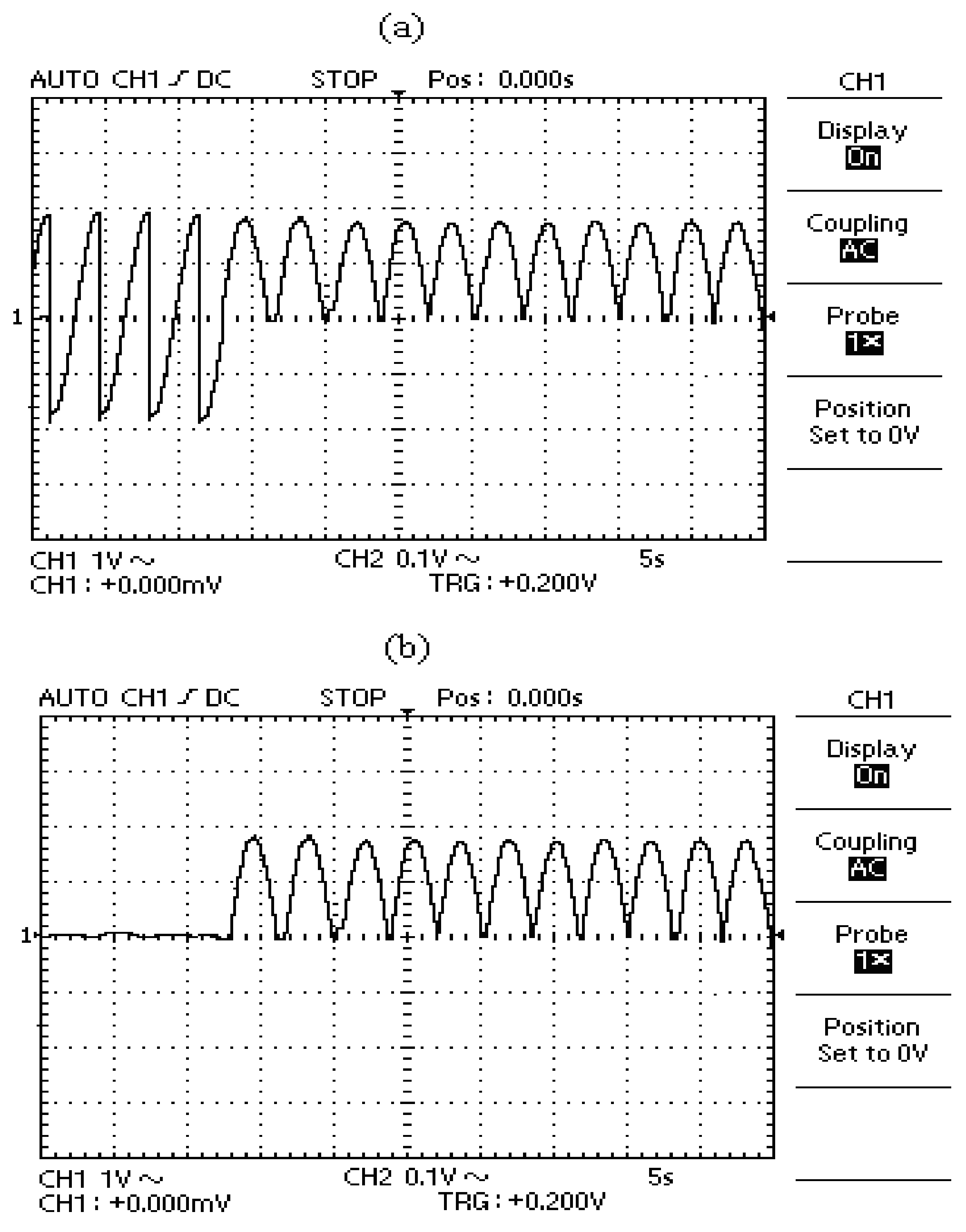
5. Experimental Results

Considering Figure 2a, a test circuit is built, which is presented in Figure 9. The circuit parameters of the CDBFCL are the same as those used in the simulation as listed in Table 2. In the test circuit, the semiconductor switches are thyristors (BT137, NXP Semiconductors N.V., Eindhoven, Netherlands), and an AVR micro-controller (Atmega 16, Atmel, Trondheim, Norway) is used for the control of the required firing angle of the shunt bridge switches. The experimental results of the proposed CDBFCL are shown in Figure 10 and Figure 11. Figure 10a,b show the NSDR current and fault current, which are limited in 3A during a fault. Figure 11a demonstrates the shunt bridge voltage, which is in fair agreement with Figure 7a. It is shown that the shunt bridge voltage is changed in contrast with the series bridge voltage to limit fault current during fault. Figure 11b presents the series bridge voltage, which is in fair agreement with Figure 7b. Considering Figure 11b, it is approximately zero during normal operating conditions. Comparison analysis between the simulation results and experimental results reveals that there is good agreement between the simulated and measured results.

6. Conclusions

In this paper, a new CDBFCL with NSDR has been proposed for use in micro-grids. It consists of series and shunt bridges and a conventional NSDR instead of the superconducting reactor. To demonstrate the proposed CDBFCL’s capabilities, it has been simulated in PSCAD/EMTDC and a prototype has been built. Considering both experimental and simulation results, the following points were observed: the shunt bridge of CDBFCL provides a variable DC voltage, which compensates for the voltage drop of CDBFCL in the DC side due to NSDR resistance in the normal operating mode; it produces DC voltage against the series bridge voltage, which limits the fault current level during fault; it can control the fault current magnitude during fault; there is good agreement between the simulation and experimental results, which reveals the effectiveness of the proposed CDBFCL.

Author Contributions

Conceptualization, investigation, and writing—original draft preparation, M.F., H.S.K. and M.S.; writing—review and editing and supervision, S.M. and K.-H.H. All authors have read and agreed to the published version of the manuscript.

Funding

This research received no external funding.

Data Availability Statement

The data presented in this study are available on request from the corresponding author.

Conflicts of Interest

The authors declare no conflict of interest.

References

  1. Liu, X.; Wang, P.; Loh, P.C. A hybrid AC/DC microgrid and its coordination control. IEEE Trans. Smart Grid. 2011, 2, 278–286. [Google Scholar]
  2. Mirsaeidi, S.; Dong, X.; Shi, S.; Tzelepis, D. Challenges, advances and future directions in protection of hybrid AC/DC microgrids. IET Renew. Power Gener. 2017, 11, 1495–1502. [Google Scholar] [CrossRef] [Green Version]
  3. Kim, M.S.; Kim, W.; Kim, J.O. Determining the location of superconducting fault current limiter considering distribution reliability. IET Gener. Transm. Distrib. 2012, 6, 240–247. [Google Scholar]
  4. Heidary, A.; Radmanesh, H.; Rouzbehi, K.; Gharehpetian, G.B. Inductive fault current limiters: A review. Electr. Power Syst. Res. 2020, 187, 106499. [Google Scholar] [CrossRef]
  5. Chen, X.; Liang, Y.; Wang, G.; Li, H. Parameter optimization design method for a fast-switch-based fault current limiter and circuit breaker. Int. J. Electr. Power Energy Syst. 2019, 114, 105377. [Google Scholar] [CrossRef]
  6. Firouzi, M.; Aslani, S.; Gharehpetian, G.B.; Jalilvand, A. Effect of superconducting fault current limiters on successful interruption of circuit breakers. In Proceedings of the International Conference on Renewable Energies and Power Quality (ICREPQ 2012), Santiago de Compostela, Spain, 28–30 March 2012. [Google Scholar]
  7. Gilvanejad, M.; Gharehpetian, G.B. A survey on fault current limiters: Development and technical aspects. Int. J. Electr. Power Energy Syst. 2020, 118, 105729. [Google Scholar]
  8. Kozak, J.; Majka, M. Comparisons of Inductive and Resistive Superconducting. IEEE Trans. Appl. Supercond. 2013, 23, 227–232. [Google Scholar] [CrossRef]
  9. Zheng, F.; Deng, C.; Chen, L.; Li, S.; Liu, Y. Transient Performance Improvement of Microgrid by a Resistive Superconducting Fault Current Limiter. IEEE Trans. Appl. Supercond. 2015, 25, 5602305. [Google Scholar]
  10. Shafaghatian, N.; Heidary, A.; Radmanesh, H.; Rouzbehi, K. Micrograms Interconnection to Upstream AC Grid Using a Dual-function Fault Current Limiter and Power Flow Controller: Principle and Test Results. IET Energy. Syst. Integr. 2019, 1, 269–275. [Google Scholar] [CrossRef]
  11. Firouzi, M.; Nasiri, M.; Mobayen, S.; Gharehpetian, G.B. Sliding Mode Controller-Based BFCL for Fault Ride-Through Performance Enhancement of DFIG-Based Wind Turbines. Complexity 2020, 2020, 1–12. [Google Scholar] [CrossRef]
  12. Chen, L.; He, H.; Chen, H.; Wang, L.; Zhu, L.; Shu, Z.; Tang, F.; Yang, J. Study of a Modified Flux-Coupling-Type SFCL for Efficient Fault Ride-Through in a PMSG Wind Turbine Under Different Types of Faults. Can. J. Electr. Comput. Eng. 2017, 40, 189–200. [Google Scholar]
  13. Firouzi, M.; Gharehpetian, G.B. LVRT Performance Enhancement of DFIG-Based Wind Farms by Capacitive Bridge-Type Fault Current Limiter. IEEE Trans. Energy. Convers. 2018, 9, 1118–1125. [Google Scholar] [CrossRef]
  14. Rezaee, M.; Harley, R.G. Resonance-Based Fault Current Limiters: Theory, Applications, and Assessment. IEEE Trans. Ind. Appl. 2018, 54, 3066–3076. [Google Scholar] [CrossRef]
  15. Moghimian, M.; Radmehr, M.; Firouzi, M. Series Resonance Fault Current Limiter (SRFCL) with MOV for LVRT Enhancement in DFIG-Based Wind Farms. Electr. Power Compon. Syst. 2020, 47, 1814–1825. [Google Scholar] [CrossRef]
  16. Ghanbari, T.; Farjah, E.; Naseri, F. Power quality improvement of radial feeders using an efficient method. Electr. Power Syst. Res. 2018, 163, 140–153. [Google Scholar] [CrossRef]
  17. Rashid, G.; Ali, M.H. Fault ride through capability improvement of DFIG based wind farm by fuzzy logic controlled parallel resonance fault current limiter. Electr. Power Syst. Res. 2017, 146, 1–8. [Google Scholar] [CrossRef]
  18. Abramovitz, A.; Smedley, K.M. Survey of Solid-State Fault Current Limiters. IEEE Trans. Power Electron. 2012, 27, 2770–2782. [Google Scholar]
  19. Rashid, G.; Ali, M.H. Transient Stability Enhancement of Double Fed Induction Machine Based Wind Generator by Bridge-Type Fault Current Limiter. IEEE Trans. Energy. Convers. 2015, 30, 939–947. [Google Scholar] [CrossRef]
  20. Kartijkolaie, H.S.; Radmehr, M.; Firouzi, M. LVRT capability enhancement of DFIG-based wind farms by using capacitive DC reactor-type fault current limiter. Int. J. Electr. Power Energy. Syst. 2018, 102, 287–295. [Google Scholar] [CrossRef]
  21. Firouzi, M. A modified capacitive bridge-type fault current limiter (CBFCL) for LVRT performance enhancement of wind power plants. Int. Trans. Electr. Energy Syst. 2018, 28, 2505. [Google Scholar] [CrossRef]
  22. Sato, T.; Yamaguchi, M.; Terashima, T.; Fuku, S.; Ogawa, J.; Shimizu, H. Study on the Effect of Fault Current Limiter in Power System With Dispersed Generators. IEEE Trans. Appl. Supercond. 2007, 17, 2331–2334. [Google Scholar] [CrossRef]
  23. Lee, S.; Lee, C.J.; Ahn, M.C.; Kang, H.; Bae, D.K.; Ko, T.K. Design and Test of Modified Bridge Type Superconducting Fault Current Limiter With Reverse Magnetized Core. IEEE Trans. Appl. Supercond. 2003, 13, 2016–2019. [Google Scholar]
  24. Radmanesh, H.; Fathi, S.H.; Gharehpetian, G.B.; Heidary, A. BridgeType Solid-State Fault Current Limiter Based on AC/DC Reactor. IEEE Trans. Power Deliv. 2016, 31, 200–209. [Google Scholar]
  25. Ise, T.; Nguyen, N.H.; Kumagai, S. Reduction of Inductance and Current Rating of the Coil and Enhancement of Fault Current Limiting Capability of a Rectifier Type Superconducting Fault Current Limiter. IEEE Trans. Appl. Supercond. 2001, 11, 1932–1935. [Google Scholar] [CrossRef]
  26. Jafari, M.; Naderi, S.B.; Hagh, M.T.; Abapour, M.; Hosseini, H. Voltage Sag Compensation of Point of Common Coupling (PCC) Using Fault Current Limiter. IEEE Trans. Power Deliv. 2011, 26, 2638–2646. [Google Scholar] [CrossRef] [Green Version]
  27. Firouzi, M.; Shafiee, M.; Gharehpetian, G.B. Multi-Resistor Bridge-Type FCL for FRT Capability Improvement of DFIG-based Wind Farm. IET Energy. Syst. Integr. 2020, 2, 316–324. [Google Scholar] [CrossRef]
  28. Firouzi, M.; Nasiri, M.; Benbouzid, M.; Gharehpetian, G.B. Application of multi-step bridge-type fault current limiter for fault ride-through capability enhancement of permanent magnet synchronous generator-based wind turbines. Int. Trans. Electr. Energy 2020, 30, e12611. [Google Scholar] [CrossRef]
  29. Hagh, M.T.; Abapour, M. Non-superconducting Fault Current Limiter with Controlling the Magnitudes of Fault Currents. IEEE Trans. Power Electron. 2009, 24, 613–619. [Google Scholar] [CrossRef]
  30. Orosz, T.; Tamus, Z.Á. Non-linear Impact of the Short Circuit Impedance Selection on the Cost Optimized Power Transformer Design. Period. Polytech. Electr. Eng. Comput. Sci. 2020, 64, 221–228. [Google Scholar] [CrossRef] [Green Version]
Figure 1. Proposed controllable dual-bridge fault current limiter (CDBFCL).
Energies 14 01026 g001
Figure 2. (a) Single phase model for analytical analysis, (b) equivalent circuit of the CDBFCL on the DC side.
Energies 14 01026 g002
Figure 3. CDBFCL performance in both normal and fault operating conditions.
Energies 14 01026 g003
Figure 4. Control system of the conventional bridge-type FCL (BFCL).
Energies 14 01026 g004
Figure 5. Control system of proposed CDBFCL.
Energies 14 01026 g005
Figure 6. (a) Fault current for two scenarios including without FCL and with the CDBFCL, (b) non-superconducting DC reactors (NSDR) and fault current in presence of CDBFCL.
Energies 14 01026 g006
Figure 7. Voltage of (a) shunt bridge voltage (Vsh) and (b) series bridge voltage (Vse).
Energies 14 01026 g007
Figure 8. CDBFCL performance for two firing angles: (a) firing angle, (b) mean value of shunt bridge voltage, (c) fault current.
Energies 14 01026 g008
Figure 9. Laboratory test set-up.
Energies 14 01026 g009
Figure 10. CDBFCL (a) NSDR current and (b) fault current.
Energies 14 01026 g010
Figure 11. CDBFCL (a) shunt and (b) series bridges voltages.
Energies 14 01026 g011
Table 1. Simulated system parameters.
ParameterValue
Source voltage (Vs)10 kV, 50 Hz
Source resistance (Rs)1 Ω
Source inductance (Ls)1 mH
NSDR inductance (LD)0.5 H
NSDR resistance (RD)2 Ω
Load resistance (RL)12 Ω
Load inductance (LL)0.01 H
Table 2. Experimental setup parameters.
ParameterValue
Source voltage (Vs)110 V, 50 Hz
LD0.1 H
RD1 Ω
Load resistance20 Ω
Load inductance0.1 H
Publisher’s Note: MDPI stays neutral with regard to jurisdictional claims in published maps and institutional affiliations.

