Abstract
Inverter-based resources (IBRs) exhibit different short-circuit characteristics compared to traditional synchronous generators (SGs). Hence, increased uptake of IBRs in the power system is expected to impact the performance of traditional protective relay schemes—set under the assumption of a SG-dominated power system. Protection engineers need to study these challenges and develop remedial solutions ensuring the effectiveness of system protection under higher levels of IBRs. To address this need, this paper studies the impact of IBRs on a variety of protective relay schemes including line distance protection, memory-polarized zero sequence directional protective relay element, negative sequence quantities-based protection, line current differential protection, phase comparison protection, rate-of-change-of-frequency, and power swing detection. For each protection function, potential misoperation scenarios are identified, and recommendations are provided to address the misoperation issue. The objective is to provide an improved understanding of the way IBRs may negatively impact the performance of traditional protection schemes as a first step towards developing future remedial solutions ensuring effective protection under high share of IBRs.
1. Introduction
The integration of renewable energy resources in the power system is increasing worldwide due to recent advancements and the continuously decreasing cost of wind turbine generator (WTG) and photovoltaic (PV) cell technologies. Solar plants, as well as Type IV WTGs (also referred to as full-size converter (FSC)) and Type III WTGs (also referred to as doubly-fed induction generator (DFIG)) are connected to electrical grids through power electronic converters, thus in this paper are referred to as inverter-based resources (IBRs).
This power electronic interface is a fundamental physical difference between IBRs and traditional synchronous generators (SGs) which results in different fault current characteristics [1,2] and requires fundamental changes in the conventional computation methodology of short circuit currents [3,4,5]. The fault current of a SG is of high amplitude, uncontrolled, and predominantly defined by the electrical parameters of the source and the impedance of short-circuit path; by contrast, the fault current of an inverter-based resource (IBR) typically has a low amplitude and is tightly controlled through fast switching of power electronics devices dependent upon manufacturer specific and often proprietary IBR control scheme. In summary, the fault current response of an IBR is low-amplitude and non-universal.
The different fault current response of an IBR has an anticipated impact on the performance of legacy protective relays [6,7,8,9,10,11,12,13,14,15,16,17,18,19,20,21,22,23,24,25,26,27]. Traditionally, relays have been set with expectation of fault current signatures of a SG-dominated power system, i.e., a high amplitude and inductive short-circuit current, which enable them to operate where they should and not operate where they should not. Increased IBR level and the ensuing change in short-circuit behavior of the power system may mean that these two fundamental principles of power system protection cannot be met. This presents a challenge for protection engineers to identify such misoperation scenarios and develop remedial solutions to ensure efficient protection under high shares of IBRs, which is addressed in this paper.
Several references have studied the performance of protective relay schemes under IBRs including line distance protection [6,7,8,9,10,11,12,13,16,18], negative sequence components based protection [8,15,16,17,18,19,20,21,24,25,26], communication-assisted protection [15,24,25], fault identification (FID) [15,24,25], rate-of-change-of-frequency (ROCOF), and power swing protection [14,16,27]. This paper reviews the key findings of these studies; further, the paper studies for the first time the performance of memory-polarized directional overcurrent protective relay elements, line current differential (LCD) protection, and phase comparison (PC) protection under IBRs. In addition to identification of potential IBR-related protection misoperation issues, the paper provides recommendations on how to circumvent the misoperation. A considered solution is the adoption of the recent grid code requirement for IBR negative-sequence current (I2) control, e.g., per VDE-AR-N 4120 Technical Connection Rules [28] (referred hereafter to as the “German grid code”), and the paper studies its effectiveness in addressing the misoperation issues. The objective of the paper is to provide an improved understanding of the way IBRs may negatively impact the performance of traditional protection schemes as a first step towards developing future remedial solutions ensuring effective protection under high share of IBRs.
It should be mentioned that the paper considers IBRs connected to an AC transmission system, and DC/DC converters or DC power system are not within the scope of the paper. The case studies and simulation tests have been conducted within the EMTP software environment.
2. Short-Circuit Response of IBRs
The most influential factor determining the fault response of an IBR is the control scheme which manages the fast switching of power electronic devices to achieve a number of control objectives. A key objective is to constrain the magnitude of current within the thermal withstand capability of power electronic switches. Other control objectives may be imposed by grid code. This dependence on control scheme and power electronic aspects leads to the following typical IBR fault current characteristics.
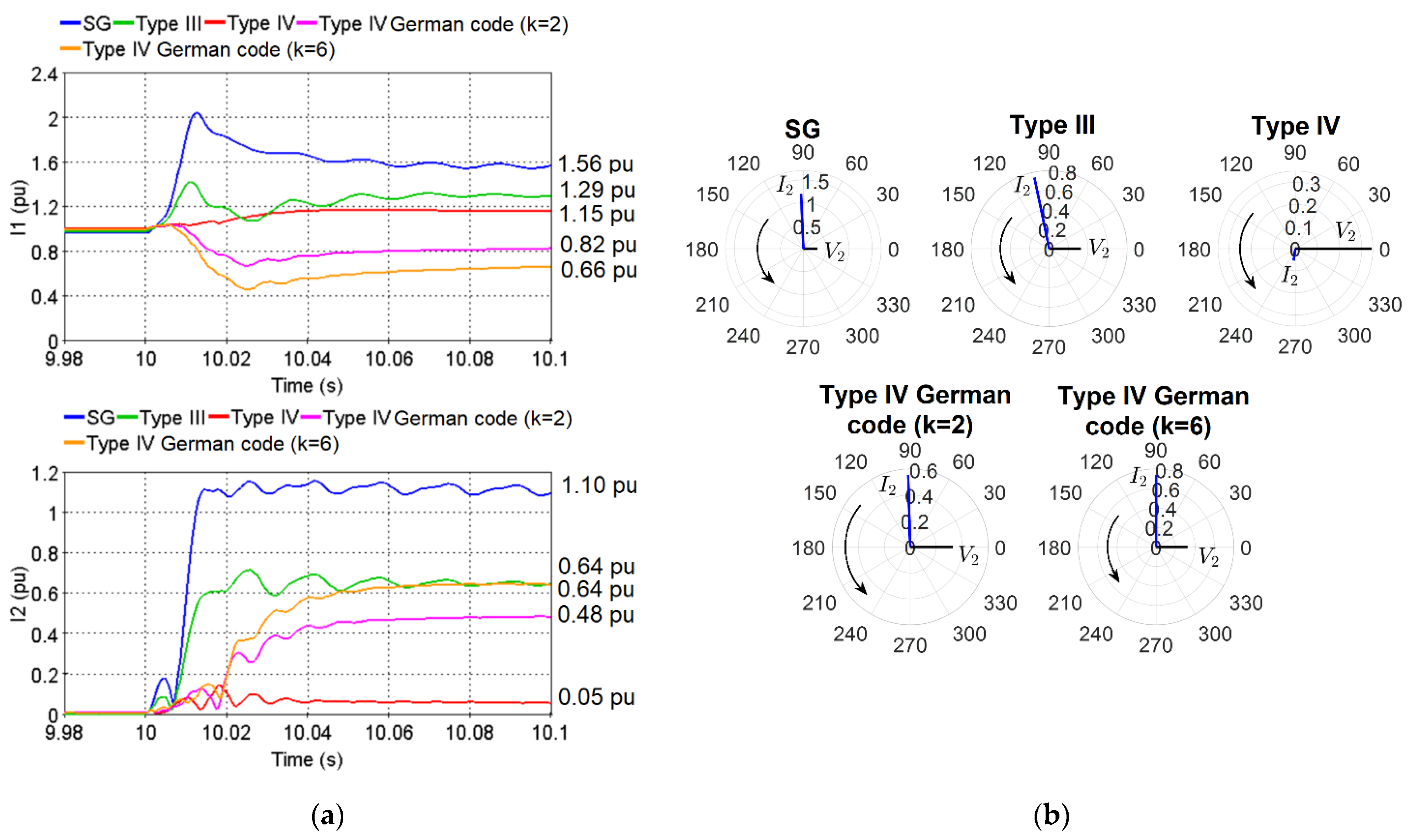
- Fault current amplitude: The amplitude of the continuous fault current contributed by an IBR has a nonlinear dependence on inverter terminal voltage [29] and is typically low since it is constrained by the converter current limiter to values close to nominal load current. Table 1 presents the fault current contribution of an example Type IV-based IBR as a function of terminal voltage. Figure 1a compares the fault current of a SG, a Type III-, and a Type IV-based IBR for a given unbalanced fault. As shown, for the same induced short-circuit voltage, the positive-sequence current (I1) and I2 contributed by a Type IV IBR have the lowest amplitude, with amplitude of I1 being close to nominal load current and amplitude of I2 being close to zero. This low amplitude fault current may negatively impact the performance of protection functions using a supervising overcurrent element such as a distance relay.
 Table 1. Fault current contribution of an example Type IV-based IBR as a function of terminal voltage.
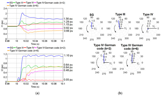 Figure 1. (a) Comparison of the amplitude of I1 and I2 of a SG, a Type III-, and a Type IV-based inverter-based resources (IBR) under the German grid code with various values of characteristic proportional gain k; (b) Phasor of V2 and I2 of a SG, a Type III-, and a Type IV-based IBR under the German grid code with various values of characteristic proportional gain k.
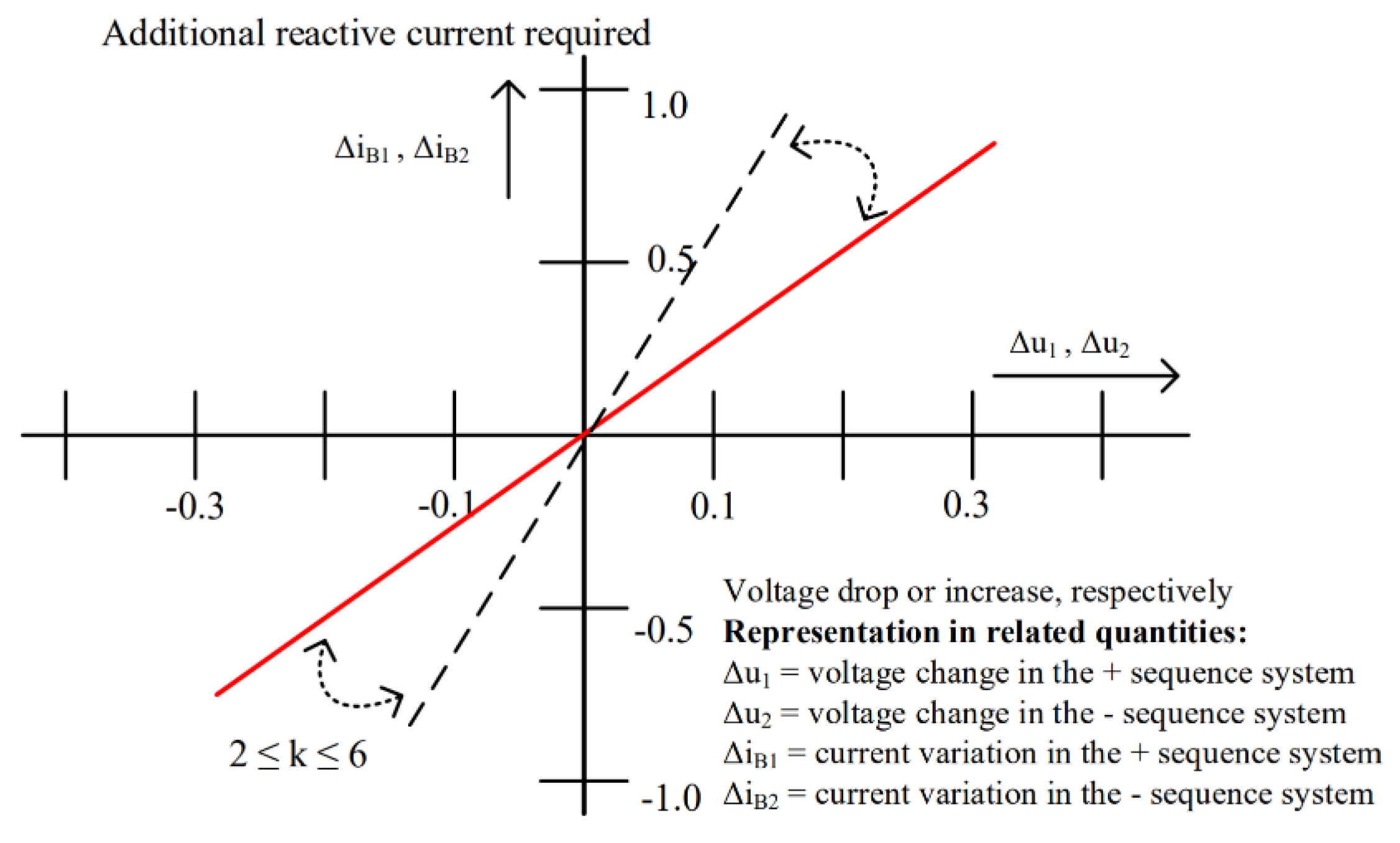
 - Fault sequence quantities: The inverter fault current does not include zero-sequence component (although zero-sequence current may still flow at the terminals of an IBR when connection to earth is provided by a transformer with a high-side, wye-grounded winding.) Further, I2 is typically partially or entirely suppressed depending on the inverter control [1]. Figure 1a shows that the I2 of a Type IV IBR is close to zero due to the nature of the traditional inverter coupled control scheme [3]. This lack of I2 may lead to protection misoperation problems, and hence grid codes have recently added requirements for IBR I2 injection during unbalanced faults. An example is the German grid code [28] which requires IBRs to inject a reactive I2 based on the characteristic curve of Figure 2 defined by a characteristic proportional gain k with a recommended value between 2 and 6. Figure 1a shows the impact of k = {2, 6} on the fault response of the Type IV IBR. As shown, I2 increases with the increased gain; nevertheless, I1 decreases since the total amplitude of the converter current is limited.
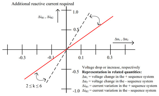 Figure 2. Characteristic curve for IBR I2 injection based on the German grid code [28].
 - Fault current power factor/phase angle: The fault current of an IBR has a dynamically changing phase angle depending on IBR control scheme and the amplitude of inverter terminal voltage, as shown in Table 1 [29]. Further, in contrast to a SG whose fault current is predominantly inductive, the fault current of an IBR may be either resistive, inductive, or capacitive. The control mode considerably impacts the angular relationship between on-fault voltages and currents near the IBR which is required by some protection functions (e.g., directional elements) for correct operation. Figure 1b compares the relative phase angle of I2 and negative-sequence voltage (V2) for a SG, a Type III-, and a Type IV-based IBR. As shown, for the SG and Type III IBR, I2 is predominantly inductive (i.e., I2 injected by the generator into the grid leads V2 by about 90°). However, the behavior is different under Type IV where I2 is predominantly capacitive (lagging V2 by about 90°). This changed angular characteristics may lead to misoperation of protection functions relying on the phase angle of I2/V2 for proper operation. The paper provides examples of such misoperation problems. This could be addressed by reactive I2 injection, e.g., based on the German grid code, in which case the phase angle becomes predominantly inductive, as shown in Figure 1b for k = {2, 6}.
- Fault current duration: The amount of time an inverter can continuously inject overcurrent into the grid during a fault depends on the inverter control and thermal limits of the power electronics.
- Rate of change of frequency: IBRs have no inherent rotational inertia (some grid codes mandate that wind generators have the capability to provide a synthetic inertial response [30]). Hence, large-scale integration of IBRs is expected to increase the rate of change of system frequency following large system disturbances such as loss of a major generation infeed. Furthermore, faster power swings are expected under high shares of IBRs due to the reduced inertia.
3. Review of Impact of IBRs on System Protection
The different fault current characteristics of IBRs has an anticipated impact on the performance of legacy protective relays—set with the expectation of short-circuit characteristics of a SG-dominated power system. This necessitates revision of their performance under IBRs, identification of potential misoperation scenarios, and development of remedial solutions to circumvent the issue and ensure effective protection under IBRs. This section studies the impact of IBRs on a variety of commonly used transmission system protection schemes. Table 2 presents a summary of key findings.
Table 2.
Summary of the main findings regarding the impact of IBRs on system protection.
3.1. Line Distance Protection
References [16,18] have illustrated that IBRs may negatively impact the performance of a distance relay in two ways, namely reduced reach accuracy and misoperation due to lack of enough supervising current.
3.1.1. Reduced Reach Accuracy
This impact relates to the dynamic expansion of a memory-polarized mho distance circle [31,32]. Basically, memory polarization causes mho distance circle to exhibit an initial expansion whose characteristics depend on the amplitude and phase angle of source impedance behind the relay. In traditional SG-dominated power systems, this impedance is predictable and consistent allowing the reach to be calculated to provide an additional resistive fault coverage capability. By contrast, under IBRs the impedance becomes variable due to the dynamically changing internal impedance of IBRs, thus leading to inconsistent expansion of the mho circle. This reduces the resistive fault coverage capability and may lead to further over- or under-reach problems.
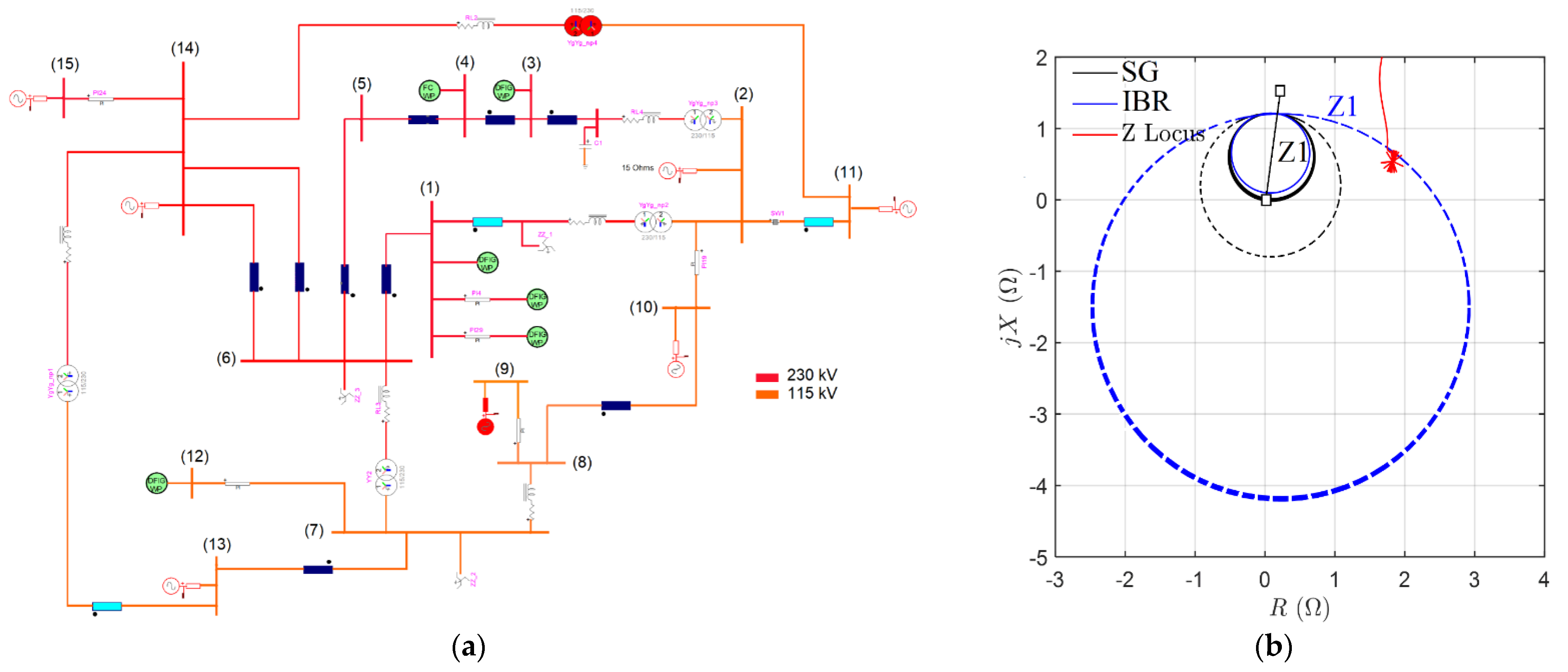
To illustrate this misoperation, a simulation study has been conducted on a 230/115 kV multi wind park (WP) test system shown in Figure 3a. The model represents a portion of an actual North American transmission system. A distance relay on bus (1) protects the line connecting bus (1) to bus (2). The relay uses a memory-polarized mho circle characteristic. A mid-line phase-A-to-ground fault with a fault resistance of Rf = 1.6 Ω (equivalent to 20 Ω on the primary side of current transformer (CT) and voltage transformer (VT)) has been applied on the protected line. The mho element of the line distance relay uses cross polarization with a memory duration of 0.2 s providing an initial resistive reach of approximately 1 Ω when the source impedance behind the relay is characterized by a strong system. Given that this initial resistive reach is smaller than the fault resistance, successful distance relay operation means that zone 1 should not pick up. The fault has been simulated under two scenarios: (i) Scenario 1 in which the corridor connecting bus (1) to bus (6) is closed and the impedance behind the relay is characterized by a strong connection; and (ii) Scenario 2 in which the corridor is open, e.g., due to a scheduled maintenance, and hence the impedance is characterized by the dynamically changing source impedance of the three WPs connected to bus (1). The simulation test has been conducted within the EMTP software environment [33] using a generic EMT model of a wind generator [34].
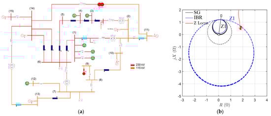
Figure 3.
(a) The 230/115 kV test system and (b) comparison of dynamic expansion of a memory-polarized distance mho circle under synchronous generators (SG) and IBR.
Figure 3b shows the dynamic expansion of the mho circle under the two scenarios. As shown, in Scenario 1 where connection to a strong grid is available, the mho circle expands to approximately 1 Ω as predicted, and the expanded mho circle does not include the fault impedance trajectory, as expected. However, in Scenario 2 the mho circle exhibits a larger expansion exceeding the calculated reach of 1 Ω, and zone 1 unintentionally picks up. The cause of this unintentional operation is the dynamically changing source impedance of the WPs on bus (1).
Recommendations—Reference [18] has provided further examples of such a misoperation and shown that the extent of this expansion is variable depending on factors such as WP operating conditions, number of WTG units in service, and wind speed. Given these effects, assessing the risk of over- or under-reach and reduced reach accuracy requires detailed three-phase analytic model simulation of IBRs [7].
3.1.2. Misoperation due to Low Supervising Current
The operation of a distance relay is commonly supervised by some minimum phase current. This element ensures that distance relay elements get activated only when the current amplitude is larger than a pre-specified threshold. The low amplitude of fault current under IBRs may result in lack of enough supervising current, thus leading to misoperation of the distance element.
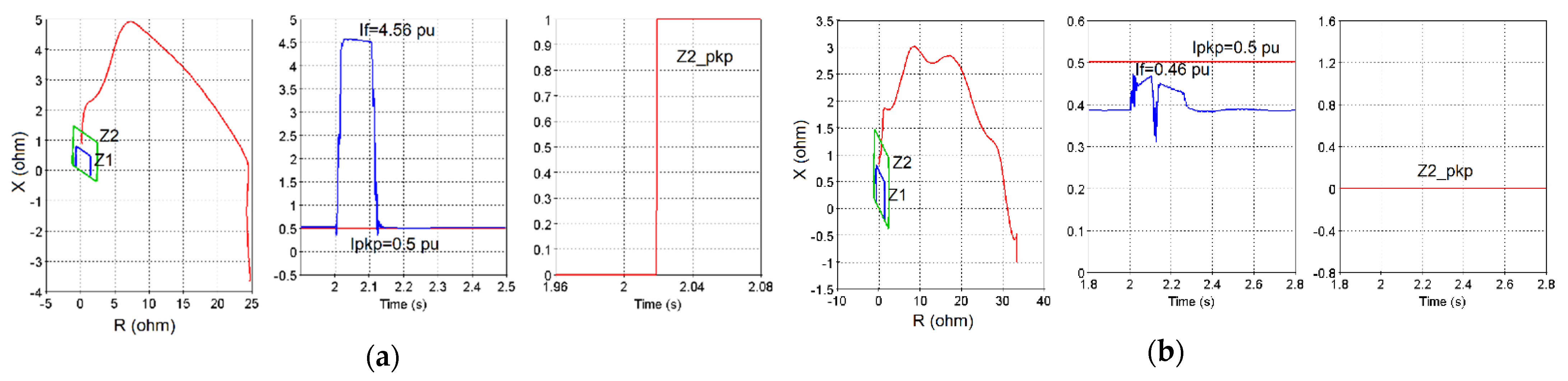
To illustrate this misoperation, a pilot protection scheme protecting the line connecting bus (3) to bus (4) is considered. The scheme is realized by forward zone 2 of two distance relays on buses (3) and (4) looking toward the protected line. The phase distance element is supervised by a phase over current element with a pickup setting of Ipkp = 0.5 pu. A 100 ms phase-A-to-phase-B fault has been applied at 95% of the protected line from the relay on bus (4). Zone 2 of the phase distance element should instantaneously pick up and communicate a permissive trip key to the remote relay. The fault has been simulated under two scenarios: (i) Scenario 1, denoted by SG in the figure, in which the corridor connecting bus (4) to bus (6) is closed, and hence the fault current measured by the distance relay on bus (4) is predominantly supplied by a strong system and (ii) Scenario 2, denoted by IBR in the figure, in which the corridor is open, and hence the fault current is exclusively supplied by the WP on bus (4) which is an FSC type.
Figure 4a,b show the response of the distance relay in Scenario 1 and Scenario 2, respectively. As shown, in Scenario 1 with a strong grid the apparent fault impedance trajectory enters zone 2, the measured fault current If = 4.56 pu is above the pickup threshold of Ipkp = 0.5 pu, and zone 2 successfully picks up and instantaneously issues Z2_pkp signal. By contrast, in Scenario 2 with IBR, the measured fault current becomes If = 0.46 pu which is below the pickup threshold, the supervising overcurrent element does not pick up, and the zone 2 distance element fails to pick up. The cause of this misoperation is lack of enough supervising current due to the low amplitude of the fault current contribution of the WP on bus (4).
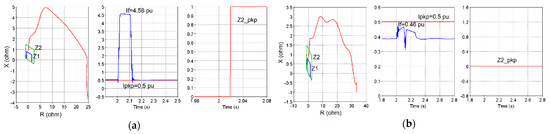
Figure 4.
Comparison of response of a distance relay to a fault in zone 2 under (a) SG and (b) IBR.
Recommendation—Potential solutions to circumvent this type of misoperation are: (i) minimally set phase overcurrent supervision; and (ii) back up undervoltage protection [7].
3.2. Zero Sequence Memory Polarized Directional Protective Relay Element
A zero-sequence directional element differentiates between faults in the forward and reverse directions by comparing the phase angle of on-fault I0 to that of a reference polarizing voltage [35]. Given that on-fault voltage amplitude may be too small to be accurately measured, the polarizing quantity is commonly defined based on a memory voltage. This memory polarization approach assumes that the phase angle of voltage does not significantly change during a fault. While this assumption is valid in traditional SG-dominated power systems due to system inertia, it may no longer be valid under high shares of IBRs due to reduced inertia and typically faster IBR control response time. This can potentially lead to faster changes in system voltage and frequency and cause a larger shift in the phase angle of the on-fault voltage with respect to the memory voltage. This increased difference may lead to an incorrect directionality decision [36,37].
To illustrate this misoperation, the 230/115 kV test system of Figure 3a has been considered. The distance relay on bus (4) uses a neutral directional overcurrent element (67N) to supervise the ground distance element. The 67N element is cross polarized with a memory duration of 0.2s with forward and reverse regions marked by “Forward” and “Reverse” in the phasor diagrams of Figure 5. A bolted phase-A-to-ground fault is applied on the protected line which is in the forward direction with respect to the relay. Successful operation means that the 67N element declares forward direction and allows the ground distance element to operate. Two scenarios have been considered: (i) Scenario 1, denoted by SG in Figure 5, in which the corridor connecting bus (2) to bus (3) is closed, and hence the fault current measured by the relay is predominantly supplied by the SG-dominated power system behind bus (2); and (ii) Scenario 2, denoted by IBR in Figure 5, in which the corridor is open and hence the fault current is exclusively supplied by the WP connected to bus (4).
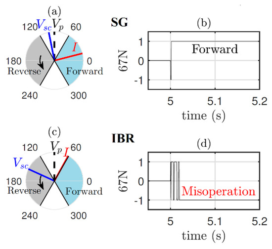
Figure 5.
Phasor diagram and response of 67N element under the two scenarios of Section 3.2: (a) phasor diagram under SG; (b) response of 67N under SG; (c) phasor diagram under IBR; and (d) response of 67N under IBR.
Figure 5a,b show the phasor diagram and response of the 67N forward element under SG. As shown, subsequent to the fault, the on-fault voltage deviates from the polarizing voltage only by about 11°, the short-circuit current lagging by about 90° falls within the forward zone, and the 67N element successfully declares forward direction. Figure 5c,d show the response under IBR. As shown, in contrast to the previous case, exhibits a significant phase shift of about 65° with respect to , the short-circuit current lagging by about 90° falls outside the forward zone, and the 67N element fails to declare forward direction. The cause of this misoperation is the larger shift of with respect to due to the faster control response time of WPs.
Recommendation—Potential solutions to circumvent this misoperation include: (1) forcing self-polarization when the phase angle shift exceeds a set threshold and (2) applying memory voltage angle compensation whereby the phase angle of the locked memory voltage is automatically compensated with a supplemental phase shift quantity [36].
3.3. Negative Sequence Components Based Protection Schemes
Several protective relaying functions are based on negative sequence quantities which indicate an unbalanced fault. These include Instantaneous Negative Sequence Overcurrent (50Q), Negative Sequence Time Overcurrent (51Q), 67Q, communication-assisted protection, phase selection/fault identification (FID), and differential protection. Quad ground distance element also uses negative-sequence quantities [38,39] but is not considered in detail in this paper. References [8,15,16,18,25,26] have studied potential misoperation scenarios for these schemes due to IBRs. These misoperation issues originate from two key differences between the fault current characteristics of IBRs and conventional SGs, namely lower amplitude and changed phase angle of I2. The lower amplitude may cause misoperation of 50Q and 51Q which rely on the amplitude of I2, and the changed phase angle may lead to misoperation of 67Q which uses the angular relationship between I2 and V2. A potential solution to these misoperation problems is to require I2 control by IBRs during an unbalanced fault. The German grid code is an example of such a requirement, and it has been shown to be capable of resolving the misoperation issues in some cases [25,26].
3.3.1. Instantaneous/Time Negative Sequence Overcurrent Element (50Q/51Q)
These elements operate when the amplitude of I2 exceeds a set threshold. Their successful operation relies on the assumption that I2 is present in substantial levels during an unbalanced fault. When the source is a SG, the amplitude of I2 is typically large enough to exceed the pickup setting and successfully operate the elements. By contrast, the low amplitude I2 under IBRs may not be sufficient to operate the elements, thus causing their misoperation.
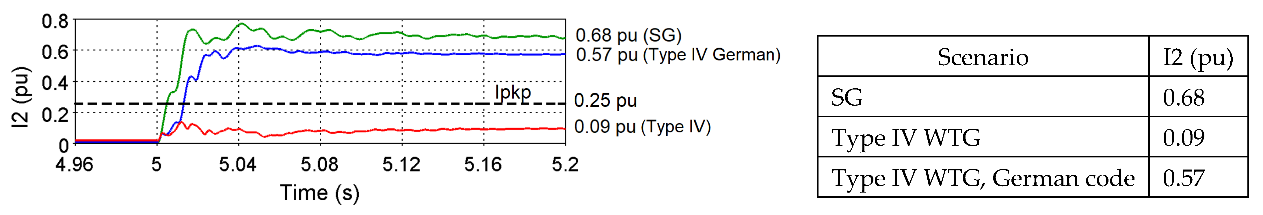
To illustrate a misoperation example, the test system of Figure 6 has been considered which represents a portion of a 315/230/120 kV transmission system including five generation units. An overcurrent relay denoted by R50 on bus (6) containing a 50Q element is used to protect the line. The negative-sequence pickup current is set at 0.25 pu. A permanent single phase-A-to-ground denoted by AG1 has been placed on the line connecting bus (6) to bus (7) at t = 5 s. Successful operation means the 50Q element asserts instantaneously. Three generation scenarios have been considered where the five generation units are based on: (i) traditional SGs; (ii) Type IV-based IBRs with no I2 control; and (iii) Type IV-based IBRs with I2 control based on the German grid code with k = 2. Figure 7 shows the time-domain amplitude of I2 and quasi steady-state values measured at 5.2 s by relay R50 under the three generator scenarios. As shown, under SG the amplitude of I2 is 0.68 pu which is above the pickup setting, and the 50Q element successfully asserts. Under Type IV with no I2 injection, the amplitude is 0.09 pu which is below the pickup, and the 50Q element fails to assert. Given that 50Q/51Q elements are commonly used in conjunction with other protective elements, their misoperation (failing to detect fault) may pose a risk to the reliability of the power system.
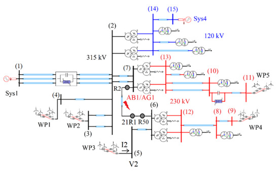
Figure 6.
Schematic diagram of the 315/230/120 kV test system.
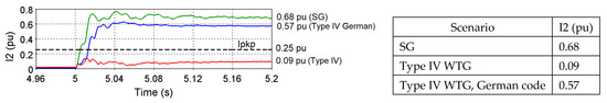
Figure 7.
Negative-sequence fault current due to fault AG1 under SG (green), Type IV wind turbine generator (WTG) with no I2 control (red), and Type IV WTG under the German grid code (blue).
Recommendation—A potential solution to the misoperation of 50Q/51Q is IBR I2 control, e.g., based on the German code. Figure 7 shows that by adopting this solution in the above case study, the amplitude of I2 is increased to 0.57 pu and the 50Q misoperation is resolved.
3.3.2. Directional Negative Sequence Overcurrent (67Q)
This element determines the direction of a fault by comparing the phase angle of I2 to that of V2 [38]. The concept is that a forward/reverse fault causes I2 to lead/lag V2 by ideally 90°. This assumption stems from the highly inductive nature of the negative-sequence network in a SG-dominated grid. Given that under IBRs I2 may be inductive/resistive/capacitive, the assumption may no longer be valid, leading to an incorrect directionality decision by 67Q.
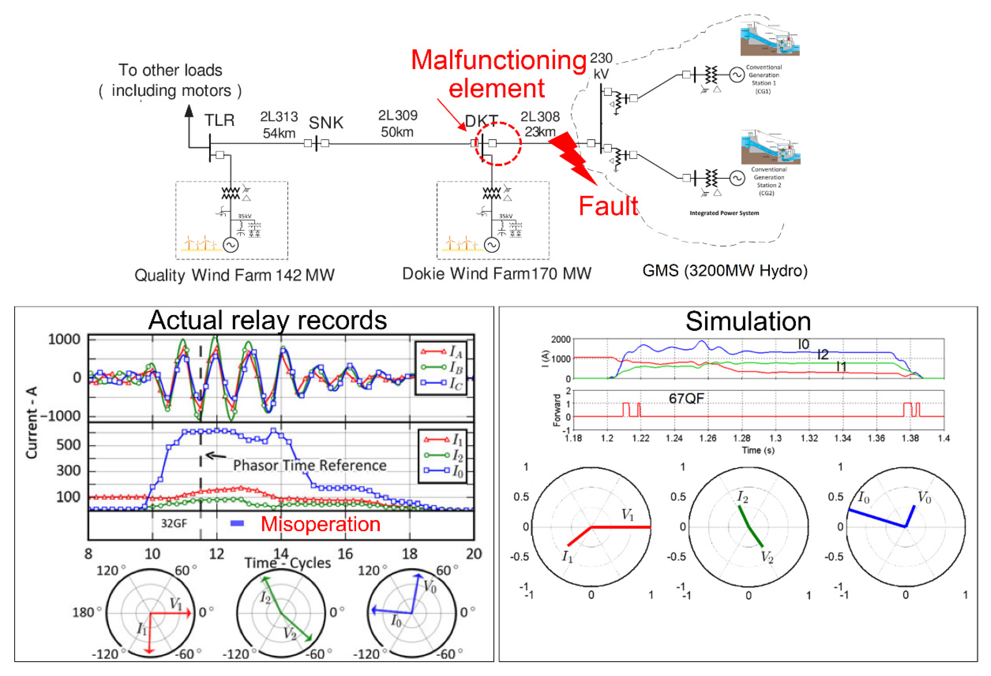
An example of such a misoperation is the 2014 event in a north American transmission system where a directional negative sequence overcurrent element failed to correctly identify the direction of a fault near a Type III WTG [26]. The reference has shown that use of POTT scheme with zero-sequence and echo logic fixes the misoperation. Figure 8 shows the system, fault records, and simulation of the event in EMTP. The system voltage is 230 kV. There are three WPs, namely Quality which is a Type III-based WP and Dokie which consists of two Type III-based WPs. A transmission line denoted by 2L308 connects the WPs to a hydro station. A relay in the DKT substation uses a directional negative sequence element looking towards line 2L308. A phase-B-to-ground fault 9.5-km from DKT substation occurred evolving into a phase-B-to-C-to-ground fault after three cycles. The fault was in the forward direction of the relay, but the forward element did not assert. Figure 8 shows the actual relay records and simulation results. The current and voltage phasors in all cases have been obtained two cycles into the BG fault. As shown, the forward element only asserts transiently since I2 leads V2 by a phase angle close to 180° which corresponds to the reverse zone. The cause is the resistive I2 contribution of the WPs. The results show an agreement between the recorded and simulated phase angle of voltage and current phasors. The discrepancy in the amplitude of sequence currents is due to modeling differences and unavailability of the full data of the system.

Figure 8.
Simulation of an actual misoperation of a directional negative sequence element due to a Type III WTG [26].
The Recommendation—Potential solutions to this misoperation include: (i) use of directional zero sequence elements instead of directional negative sequence elements for ground fault protection (assuming the IBR to be connected through a transformer that is a source of I0) [26]; (ii) IBR reactive I2 injection under unbalanced faults (e.g., per the German grid code) [25,26].
3.3.3. Communication-Assisted Protection
The misoperation of 67Q can lead to further protection malfunctions when 67Q is used as part of another protection scheme, e.g., in communication-assisted protection. This section shows this impact for the POTT scheme; similar impacts can be shown for other pilot schemes including permissive underreaching scheme (PUTT) and DCB, as shown in [18].
In the POTT scheme, the overreaching distance element (zone 2) at each line terminals sends a permissive trip key to the remote terminal. Directional elements including 67Q2 and 67Q3 are also used in some applications for more sensitive fault detection for unbalanced faults and can either supplement or replace ground distance (zone) elements in communications-assisted trip schemes. Each terminal trips upon receipt of the remote permissive key and the local permissive signal. The use of 67Q renders POTT prone to malfunction under IBRs. Basically, a possible incorrect directionality decision by 67Q causes the impacted POTT scheme not to key the permissive trip signal to the remote relay. It should be mentioned that the use of negative-sequence directional supervision in pilot protection is for additional security benefit but is not essential.
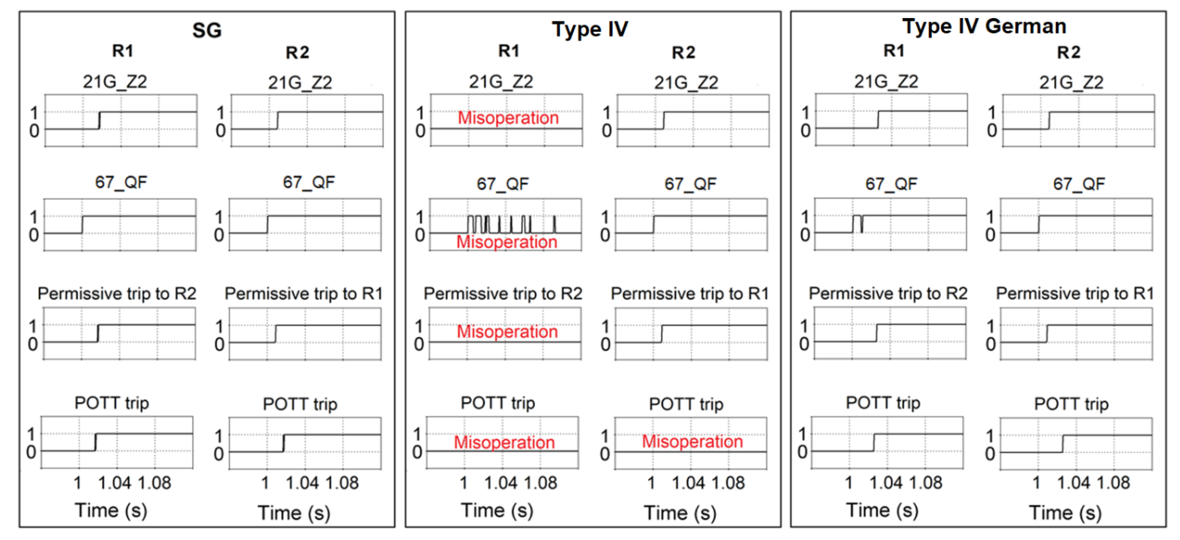
To illustrate this misoperation, A POTT scheme has been added to the test system of Figure 6 to protect the line connecting buses (6) and (7), and fault AG1 has been applied on the line. The POTT scheme is realized by two multi-function relays denoted by R1 and R2 using 21G_Z2 (ground distance zone 2) and 67Q. The POTT scheme should instantaneously trip. Successful POTT operation requires both 21G_Z2 and 67Q2 to be picked up by R1 and R2, the permissive trip to be keyed to the respective remote relay, and 21G_Z2 of each relay to trip on receipt of the permissive trip. Three generation scenarios have been considered where the generators are (i) SGs; (ii) Type IV-based IBRs with no I2 control; and (iii) Type IV-based IBRs with I2 control based on the German grid code with k = 2.
Figure 9 shows the results. Under SG the operation is successful since R1 sees the fault in zone 2 and forward direction, issues both 21G_Z2 and 67Q2, and keys permission to trip to R2. Similarly, R2 sees the fault in zone 2 and forward direction, issues both 21G_Z2 and 67_QF, and sends a permissive trip signal to R1. Under Type IV with no I2 control, 67_QF of R1 asserts only transiently. Hence, R1 fails to send a permissive signal to R2, and POTT fails to trip for the in-zone AG1 fault. The malfunctioning element is 67Q of R1, and the cause is the changed phase angle of I2 due to Type IV-based IBRs. The misoperation problem is resolved under the German grid code. In this case, due to the reactive I2 injection of WP3 and WP4, the 67Q element of R1 successfully issues 67_QF, permissive trip is sent to R2, and POTT successfully operates.

Figure 9.
Response of POTT to a ground fault on the protected line under SG, Type IV-based IBR with no I2 control, and Type IV-based IBR with I2 control based on the German code.
Recommendation—Potential solutions to eliminate this misoperation include: (i) POTT scheme with zero sequence and echo logic [26]; and (ii) IBR dynamic I2 reactive current injection (e.g., the German code). Reference [7] has provided further solutions to eliminate misoperation of DCB including minimally set overcurrent supervision elements for distance relays, direct transfer trip (DTT), and backup phase undervoltage and neutral overvoltage elements.
3.3.4. Fault Identification Logic
The FID scheme (or also known as phase selection) is used by protective elements to identify the type of a fault, i.e., single-phase-to-ground, or phase-to-phase, and the faulted phase(s) [35,40,41,42,43]. In one implementation of the FID logic the phase angle relationship between I2 and I0 is used to identify the faulted phase loop [40]. The changed phase angle of I2 under IBRs may lead to an incorrect fault identification by this FID logic.
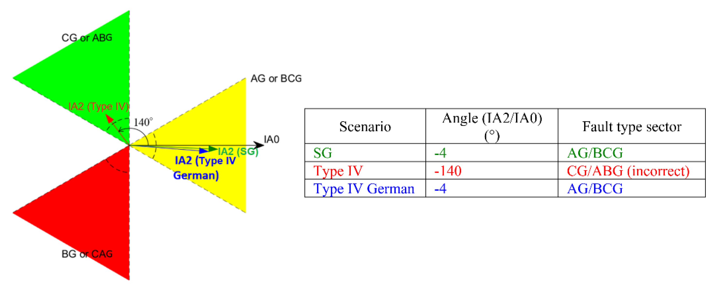
To illustrate this impact, fault AG1 is applied in the test system of Figure 6, and a distance relay denoted by 21R1 on bus (6) is used to detect the faulted phase. Figure 10 shows a graphical representation of the FID logic which uses the three colored sectors and the respective phase angle of IA2 to IA0 to classify a fault [40]. Assuming the phase angle of IA0 vector to be the reference, the fault is classified as {AG/BCG}, {CG/ABG}, or {BG/ACG} when IA2 vector falls within the yellow, green, or red sector, respectively. Three generation scenarios have been considered where the generators are: (i) SGs; (ii) Type IV-based IBRs with no I2 control; and (iii) Type IV-based IBRs with I2 control based on the German grid code with k = 2. As shown, under SG IA2 lags IA0 by about −4° which falls within the AG sector, and the FID successfully declares an AG fault. Under Type IV IBR with no I2 control, IA2 leads IA0 by about −140° which falls within the CG sector, and the FID scheme mistakenly declares a CG fault. The cause of this incorrect fault identification is the changed phase angle of I2 due to the Type IV IBRs. Under Type IV German, IA2 lags IA0 by about −4° which is within the AG sector, and the scheme successfully declares an AG fault.
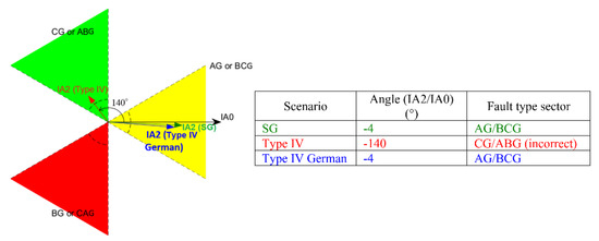
Figure 10.
Graphical representation of the sectors of fault identification (FID) and the corresponding phase selection decision: IA2 and IA0 phasors due to fault AG1 under SG (green), Type IV with no I2 control (red), and Type IV under the German grid code (blue).
It should be noted that this current-based FID only operates if the fault produces sufficient I2 and I0, otherwise FID is performed using voltage. The impact of IBRs on the voltage-based FID has not been studied in this paper.
Discussion—The above case studies suggest that IBR I2 control may resolve some of the misoperation issues in some cases. Nevertheless, this solution faces limitations since IBRs are essentially current limited devices. Even when required to inject I2 during unbalanced faults, the magnitude of this current would be limited. The limitation exists because the phasor sum of I1 (active and reactive) and I2 in any given phase cannot exceed the current limit of the converter. As such, the full extent of this behavior on traditional protection schemes is still unknown especially when the penetration of IBRs is significantly high throughout the interconnection.
3.4. Line Current Differential Protection
The LCD protection (87L) is a communication-assisted protection scheme which is used in applications such as protection of critical lines where an exceptionally secure protection is required and very short lines where distance relays may be inadequate [44]. LCD responds to the sum of current entering its zone of protection. Ideally, this sum is close to zero under all events except for an internal fault, and hence can be used as an indicator of an internal fault. The 87L elements include phase-segregated (87LP), negative-sequence (87LQ), and zero-sequence (87LG) differential elements. Existing LCD scheme include traditional LCD [45] and vendor-specific current-ratio plane (Alpha Plane) scheme [46,47]. The traditional scheme uses the amplitude of the sum of terminal currents; if the amplitude is above a user-defined threshold, an internal fault is declared. The Alpha Plane scheme uses the complex ratio of terminal currents; if this complex ratio falls within the operate region of a user-defined characteristic in the complex plane (Alpha Plane), an internal fault is declared.
The different fault current signatures of IBRs may cause an LCD relay to encounter a different current flow pattern compared to that of a SG-dominated power system. If these differences are significant, the fault current may fall within an incorrect region of the LCD characteristic, and the relay may mistakenly classify an internal fault as external. This impact may be different for the traditional scheme compared to Alpha Plane scheme due to the use of different detection algorithms.
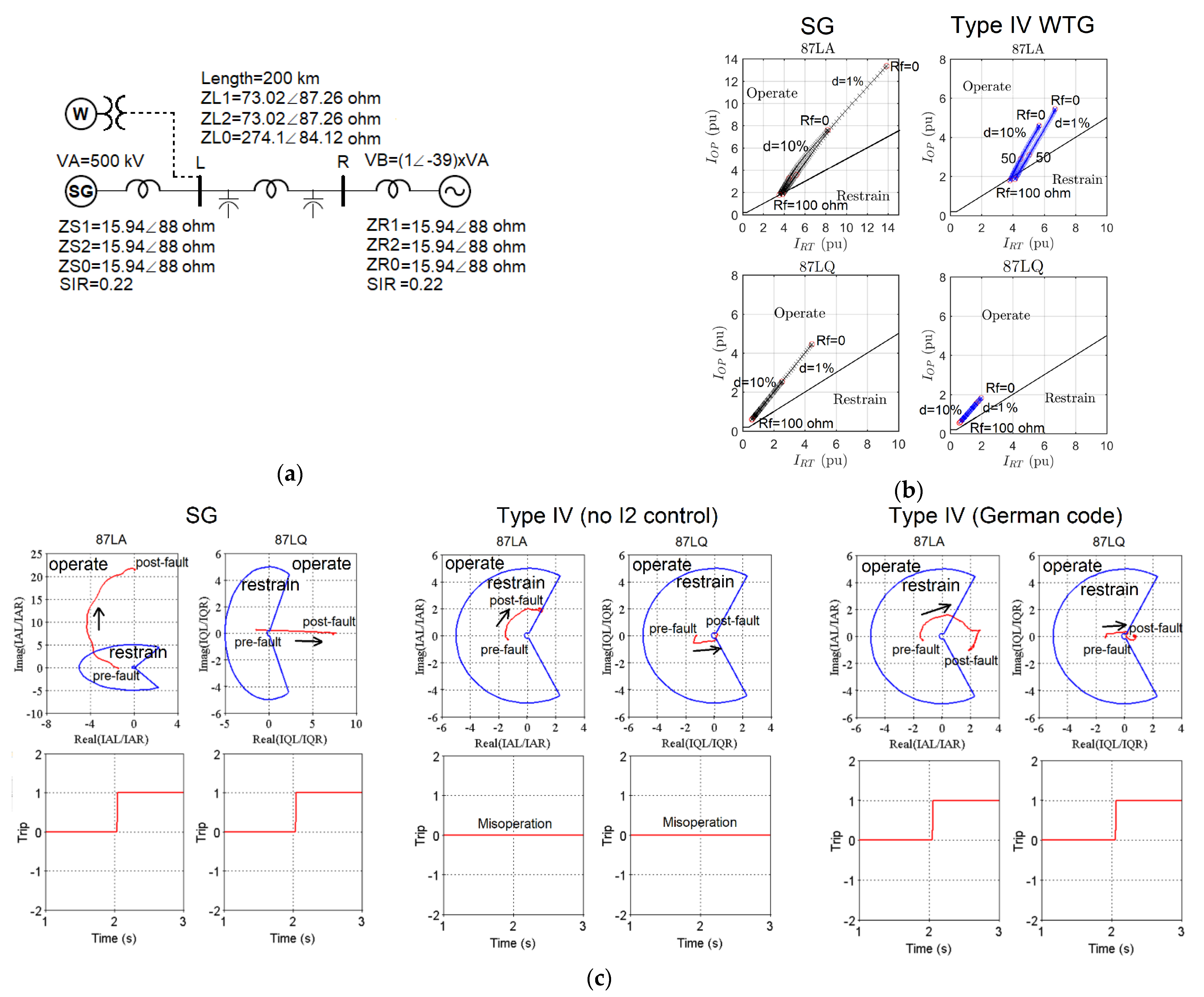
To demonstrate the effect, two simulation tests have been conducted to study the performance of an Alpha Plane LCD and a traditional LCD in the 500-kV two-source test system of Figure 11a. The LCD scheme protects the line connecting bus L to bus R. The source on bus R is a Thevenin equivalent representing a SG-dominated power system. The source on bus L represents three generation scenarios: (i) SG; (ii) type IV-based IBR with no I2 control; or (iii) Type IV-based IBR with I2 control.
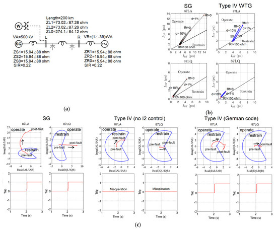
Figure 11.
(a) The 500 kV two-source test system; (b) trajectories of a traditional LCD for a phase-A-to-G fault at different locations and various fault resistance values under SG and Type IV WTG with no I2 control; and (c) trajectories of an Alpha Plane LCD for a phase-A-to-ground fault under SG, Type IV WTG with no I2 control, and Type IV WTG with I2 control based on the German grid code.
3.4.1. Traditional LCD
Figure 11b shows the response of a traditional LCD scheme to a phase-A-to-ground mid-line fault. The scheme uses single slope characteristic with a slope of 50%. The area above/below this characteristic defines the operate/restrain region of the LCD. A variety of faults at different locations and fault resistance values have been simulated, each marked by “x”. Two generation scenarios have been considered where the source on bus L represents: (i) a SG; and (ii) a Type IV based IBR with no I2 control. Since the fault is inside the protection zone, the LCD should pick up. As shown, in all considered scenarios the fault trajectory is within the operate region of the LCD, and the fault is successfully detected. Hence, the results suggesting no misoperation exclusively due to IBRs; at very high fault resistance values the fault is not detected, but this occurs under both SG and IBR.
3.4.2. Alpha Plane LCD
Figure 11c shows the trajectories of the 87L elements of an Alpha Plane LCD under the AG fault. Any point outside the circular characteristic indicates an internal fault. Prior to the fault the operating point is inside the restrain region, and an internal fault causes the trajectory to move into the operate region. Under SG, the current ratio of 87LA and 87LQ elements departs from the restraint point and enters the operate region, and the elements successfully operate. Nevertheless, under Type IV with no I2 control the trajectories remain inside the restrain zone, the 87LA and 87LQ elements fail to assert, and the internal fault is not detected. The cause of 87LQ misoperation is the low amplitude and changed phase angle of the I2 contribution of the Type IV IBR which produces a post-fault operating point inside the restraining region. The different I2 characteristics also contributes to the misoperation of 87LA. Under Type IV-based IBR with I2 control, the misoperation is fixed for both 87LA and 87LQ elements. The trajectory of the 87LQ element exits the restraining zone due to the increased amplitude of I2 and settles in an operating point close to the real axis since the terminal I2 currents are almost fully in phase. The trajectory of the 87LA element also exits the restrain zone due to the changed phase angle of ILA caused by the injected reactive I2.
Recommendation—The simulation case study suggests a risk of Alpha Plane LCD misoperation under IBRs. Conducted simulations further show the possibility of fixing the misoperation through IBR I2 control. In contrast to Alpha Plane LCD, traditional LCD seems to be immune to an IBR-related misoperation.
3.5. Rate-of-Change-of-Frequency and Power Swing Protection
With increasing penetration of IBRs, asynchronously connected to the power system, and reduction in the amount of online synchronous resources, system inertia declines. This low inertia operation may negatively impact the performance of protection schemes designed with the expectation of large inertia under traditional SGs. This ROCOF and power swing protection.
3.5.1. Rate-of-Change-of-Frequency
ROCOF protection is used to detect unintentional island formation in a power system [48,49,50,51,52]. This is performed by measuring the rate of change in frequency; a rapid change in frequency in a short period is indicative of an island formation and should trigger a trip of the generation source or the point of interconnection transformer to de-energize the island. Traditionally, the settings of ROCOF relays have been selected with the expectation of high inertia operation. Different regions use different ROCOF settings with values ranging from 0.1 Hz/s to 1 Hz/s [52,53].
With reduced system inertia due to IBR penetration, the ROCOF after loss of a generator may exceed the setting since ROCOF is inversely proportional to system inertia. Consequently, ROCOF relays may mistakenly interpret the high ROCOF as an islanding event and cause unnecessary tripping of IBRs across the system. The outcome is a power imbalance which may be greater than planned for, with potentially destabilizing consequences for the network.
Figure 12 illustrates this effect using a simulation study conducted on a European transmission system test case [14]. In this test, a dynamic event was simulated under increasing levels of IBR integration, and ROCOF was captured in each case. The results show the increased ROCOF as a function of increased IBR integration level. When IBR integration is 0% (all generators are SGs), the measured ROCOF is 0.16 Hz/s. However, in an operating condition where IBRs displace 65% of the MW generated by SGs, the ROCOF increases to 0.37 Hz/s. This trend may result in ROCOF values exceeding the setting of the relays thus causing a misoperation.
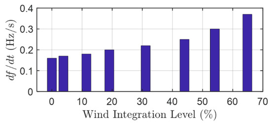
Figure 12.
Rate-of-change-of-frequency (ROCOF) as a function of IBR integration level.
Recommendation—To eliminate this misoperation, a solution is to increase the ROCOF setting in the grid code. Examples of such revisions include National Grid UK which has revised its grid code to increase the ROCOF Loss-of-Mains setting from 0.125 Hz/s to 1 Hz/s [54] and EirGrid in Ireland which has increased the setting from 0.5 Hz/s to 1 Hz/s [55]. A drawback of this approach is the resulting desensitization of islanding protection.
3.5.2. Power Swing Detection and Protection
Power swing is a temporal variation of power flow caused by system disturbances such as line switching, generator disconnection, and the loss or connection of large blocks of load [56,57,58,59]. During a power swing, system voltages and currents change, and protective relays which measure these quantities may interpret such variations as a fault and unintentionally trip needed equipment. Power swing protection protects a power system against such undesired tripping by differentiating between a fault and a power swing and blocking the operation of a target relay in the event of a power swing. The detection is based on the consideration that the rate of change of swing impedance is slow during a power swing since the rate is subject to the large rotational inertia of machines. By contrast, the rate is very fast during a fault as it is determined by the time-constant of the signal filtering mechanism of the relay.
Power swing protection has two main functions: (i) PSB which differentiates between a fault and a power swing by measuring the rate of change of swing impedance; and (ii) OST which distinguishes between a stable and unstable swing and initiates system partitioning in the event of an unstable swing to avoid a widespread outage. The settings of the PSB and OST functions are determined based on swing characteristics; the settings of the PSB function are determined based on the fastest rate of change of swing impedance, and the settings of the OST function are calculated from the swing impedance trajectory of the most severe stable swing.
The reduced inertia and changed dynamic characteristics under IBRs may change the swing trajectory of a power system, thus resulting in the following detrimental impacts [14,16,27]:
- PSB function: The increased rate of change of swing impedance vector may cause PSB to mistakenly interpret a power as a system fault and fail to declare a power swing condition. A potential solution is to reduce the time delay setting of the PSB function by finding the fastest swing in presence of IBRs. Figure 13a illustrates this misoperation by comparing the simulated swing impedance trajectory simulated under a SG-dominated power system and under 25% IBR integration. The PSB function measures the rate of change of impedance using an outer and a middle characteristic and a time delay setting of three cycles. Under SG, the swing crosses the outer and middle elements at = 5.154 s and = 5.213 s, respectively, corresponding to a time delay of 3.5 cycles. Since this time delay is larger than the PSB setting of 3 cycles, the function successfully detects the power swing and blocks the corresponding zone elements of the supervised distance relay. However, under 25% IBR the swing crosses the outer and middle elements at = 5.128 s and = 5.173 s, respectively, corresponding to a time delay of 2.7 cycles which is less than the PSB time delay setting. Consequently, the function fails to detect the swing, the impedance trajectory enters zone 2, and the distance relay unintentionally declares a fault on a healthy line. The cause of this misoperation is the higher rate of change of swing impedance caused by reduced inertia under IBR. To eliminate such a PSB misoperation, a solution is to reduce the PSB time delay. A limitation of this solution is that reducing the PSB time delay to very small values may lead to unwanted blocking of distance relay zones by the PSB function during a fault.
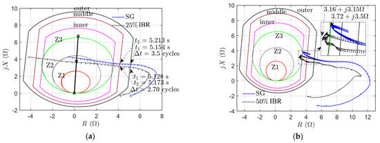 Figure 13. (a) Power Swing Blocking (PSB) misoperation due to faster swings under IBRs and (b) Out-of-Step-Tripping (OST) malfunction due to changed swing trajectory under IBRs.
 - OST function: The changed swing impedance trajectory under IBRs may cause the OST to misinterpret a stable swing as unstable. Figure 13b shows this misoperation by comparing the impedance trajectory of a stable swing under SG and under 50% IBR integration. The OST function declares an unstable swing as soon as the trajectory crosses the inner characteristic. Given that the simulated swing is stable, the OST function should not assert. As shown, under SG the swing reverses direction at 3.72 + j3.5 Ω right before crossing the inner element, and hence the swing is successfully classified as stable. Nevertheless, under 50% IBR the return point is at 3.16 + j3.15 Ω which falls inside the inner element, thus causing the OST to mistakenly classify the stable swing as an OOS condition. The consequence may be an unnecessary partitioning of the system by the OST function. Such an OST misoperation can be avoided by modifying the settings of the inner characteristic based on the trajectory of the most sever stable swing under IBRs.
- The location of EC of a power system moves as IBR generation level increases. This is due to the changed source impedance under IBRs. The movement of EC necessitates the recalculation of the location of the EC to find the optimal location to implement the OST function. EC moves toward IBRs as wind generation level increases.
- The capacity, type and GSC control options (decoupled vs. coupled) are among the key factors that impact power swing characteristics and need to be considered in protection studies as they all influence the level of impact on PSB and OST functions in addition to the location of EC.
4. Conclusions
Given the different fault response characteristics of IBRs compared to SGs, large-scale IBR integration may have detrimental impacts on the performance of system protection. This paper has studied these impacts on a variety of protection functions, identified potential misoperation challenges, and provided potential solutions to circumvent the issues and ensure effective protection under IBRs. These impacts largely stem off from the low amplitude and changed phase angle of fault current contribution of IBRs and lack of inherent rotational reduced inertia. Table 2 presents a summary of the main findings of the paper.
Future research directions include evaluating the recommended solutions to the identified protection misoperation issues. Specifically, IBR I2 control as one of the potential solutions has limitations since IBRs are current limited devices. Even when required to inject I2 during unbalanced faults, the amplitude of this current would be limited because the phasor sum of I1 and I2 in any given phase cannot exceed the current limit of the converter. Furthermore, increased I2 injection leads to reduced I1 contribution which may in turn lead to other protection challenges. As such, the full extent of IBR I2 control on traditional protection schemes is still unknown especially when the penetration of IBRs is significantly high throughout the interconnection. Another research direction is to study the impact of grid forming IBRs on the performance of system protection. Given their different control, these IBRs are expected to have a different impact on system protection compared to that of grid following IBRs studied in this paper.
Author Contributions
A.H. led the analytical work, methodology development, simulation studies, and writing of the paper. E.F. provided the overall vision and guidance. I.K. provided the simulation software and guidance on simulation studies. I.K., U.K. and E.F. provided the simulation models. E.F., I.K. and U.K. reviewed and edited the paper. All authors have read and agreed to the published version of the manuscript.
Funding
This research received no external funding.
Institutional Review Board Statement
Not applicable.
Informed Consent Statement
Not applicable.
Data Availability Statement
The data presented in this study are available on request from the corresponding author.
Conflicts of Interest
The authors declare no conflict of interest.
References
- Kou, G.; Chen, L.; VanSant, P.; Velez-Cedeno, F.; Liu, Y. Fault characteristics of distributed solar generation. IEEE Trans. Power Deliv. 2019, 35, 1062–1064. [Google Scholar] [CrossRef]
- Fault Current Contribution from Wind Plants—IEEE PSRC/Machinery/T&D Committees Report. Available online: https://www.pes-psrc.org/kb/published/reports/Fault%20Current%20Contributions%20from%20Wind%20Plants.pdf (accessed on 15 February 2021).
- Kauffmann, T.; Karaagac, U.; Kocar, I.; Jensen, S.; Farantatos, E.; Haddadi, A.; Mahseredjian, J. Short-circuit model for type-IV wind turbine generators with decoupled sequence control. IEEE Trans. Power Deliv. 2019, 34, 1998–2007. [Google Scholar] [CrossRef]
- Kauffmann, T.; Karaagac, U.; Kocar, I.; Jensen, S.; Mahseredjian, J.; Farantatos, E. An accurate type III wind turbine generator model for short circuit applications. IEEE Trans. Power Deliv. 2017, 32, 2370–2379. [Google Scholar] [CrossRef]
- Kauffmann, T.; Karaagac, U.; Kocar, I.; Gras, H.; Mahseredjian, J.; Cetindag, B.; Farantatos, E. Phasor domain modeling of type III wind turbine generator for protection studies. In Proceedings of the 2015 IEEE Power & Energy Society General Meeting, Denver, CO, USA, 26–30 July 2015; pp. 1–5. [Google Scholar]
- IEEE/NERC. Task Force on Short-Circuit and System Performance Impact of Inverter Based Generation, Impact of Inverter Based Generation on Bulk Power System Dynamics and Short-Circuit Performance; Report No. PES-TR68; IEEE: New York, NY, USA, September 2018. [Google Scholar]
- Power System Relaying and Control Committee (Subcommittee C). System Protection Working Group C32, Protection Challenges and Practices for Interconnecting Inverter Based Resources to Utility Transmission Systems; Report No. PES-TR-81; IEEE: New York, NY, USA, July 2020. [Google Scholar]
- Haddadi, A.; Farantatos, E.; Kocar, I. Protection Guidelines for Systems with Inverter Based Resources; The Electric Power Research Institute (EPRI): Palo Alto, CA, USA, 2020; 3002018717. [Google Scholar]
- Hooshyar, A.; Azzouz, M.A.; El-Saadany, E.F. Distance protection of lines connected to induction generator-based windfarms during balance faults. IEEE Trans. Sustain. Energy 2014, 5, 1193–1203. [Google Scholar] [CrossRef]
- Hooshyar, A.; Azzouz, M.A.; El-Saadany, E.F. Distance protection of lines emanating from full-scale converter-interfaced renewable energy power plants—Part I: Problem statement. IEEE Trans. Power Deliv. 2014, 30, 1770–1780. [Google Scholar] [CrossRef]
- Hooshyar, A.; Azzouz, M.A.; El-Saadany, E.F. Distance protection of lines emanating from full-scale converter-interfaced renewable energy power plants—Part II: Solution description and evaluation. IEEE Trans. Power Deliv. 2014, 30, 1781–1791. [Google Scholar] [CrossRef]
- He, L.; Liu, C.-C.; Pitto, A.; Cirio, D. Distance protection of AC grid with HVDC-connected offshore wind generators. IEEE Trans. Power Deliv. 2013, 29, 493–501. [Google Scholar] [CrossRef]
- Srivastava, S.; Biswal, A.; Ganesan, S.; Shenoy, U.J.; Srivastava, S. Behavior of self polarized Mho characteristic on lines fed from DFIG based wind farms. In Proceedings of the 2013 IEEE Innovative Smart Grid Technologies—Asia (ISGT Asia), Bangalore, India, 10–13 November 2013; pp. 1–6. [Google Scholar]
- Haddadi, A.; Farantatos, E.; Kocar, I. Impact of Inverter-Based Resources on Power Swing and Rate of Change of Frequency Protection; EPRI: Palo Alto, CA, USA, 2020; 3002016198. [Google Scholar]
- Haddadi, A.; Farantatos, E.; Kocar, I. Impact of Inverter-Based Resources on Protection Schemes Based on Negative Sequence Components; EPRI: Palo Alto, CA, USA, 2019; 3002016197. [Google Scholar]
- Haddadi, A.; Kocar, I.; Mahseredjian, J.; Karaagac, U.; Farantatos, E. System Protection Guidelines for Systems with Inverter Based Resources: Performance of Line Current Differential, Phase Comparison, Negative Sequence, Communication-Assisted, and Frequency Protection Schemes Under Inverter-Based Resources and Impact of German Grid Code; EPRI: Palo Alto, CA, USA, 2019; 3002016196. [Google Scholar]
- Haddadi, A.; Kocar, I.; Mahseredjian, J.; Karaagac, U.; Farantatos, E. Short-Circuit Phasor Models of Inverter-Based Resources for Fault Studies: Model Validation Case Studies; EPRI: Palo Alto, CA, USA, 2018; 3002013634. [Google Scholar]
- Haddadi, A.; Kocar, I.; Mahseredjian, J.; Karaagac, U.; Farantatos, E. Protection Guidelines for Systems with High Levels of Inverter Based Resources; EPRI: Palo Alto, CA, USA, 2018; 3002013635. [Google Scholar]
- Behnke, M.R.; Custer, G.; Farantatos, E.; Fischer, N.; Guttromson, R.; Isaacs, A.; Majumder, R.; Pant, S.; Patel, M.; Reddy-Konala, V.; et al. Impact of Inverter Based Resource Negative Sequence Current Injection on Transmission System Protection; Technical Report SAND2020-0265; Sandia National Laboratories: Albuquerque, NM, USA, 2020. [Google Scholar] [CrossRef]
- Kou, G.; Jordan, J.; Cockerham, B.; Patterson, R.W.; VanSant, P. Negative-sequence current injection of transmission solar farms. IEEE Trans. Power Deliv. 2020, 35, 2740–2743. [Google Scholar] [CrossRef]
- Haddadi, A.; Kocar, I.; Mahseredjian, J.; Karaagac, U.; Farantatos, E. System Protection Guidelines for Systems with High Levels of Renewables: Impact of Wind & Solar Generation on Negative-Sequence and Power Swing Protection; EPRI: Palo Alto, CA, USA, 2017; 3002010937. [Google Scholar]
- Kocar, I.; Haddadi, A.; Mahseredjian, J.; Karaagac, U.; Farantatos, E. Advanced Short-Circuit Modeling, Analysis, and Protection Schemes Design for Systems with Renewables—TVA Case Study; EPRI: Palo Alto, CA, USA, 2017; 3002010950. [Google Scholar]
- Kocar, I.; Haddadi, A.; Karaagac, U.; Kauffmann, T.; Gras, H.; Mahseredjian, J.; Farantatos, E. Impact of Renewables on System Protection: Wind/PV Short-Circuit Phasor Model Library and Guidelines for System Protection Studies; EPRI: Palo Alto, CA, USA, 2016; 3002008367. [Google Scholar]
- Haddadi, A.; Kocar, I.; Mahseredjian, J.; Karaagac, U.; Farantatos, E. Negative sequence quantities-based protection under inverter-based resources Challenges and impact of the German grid code. Electr. Power Syst. Res. 2020, 188, 106573. [Google Scholar] [CrossRef]
- Haddadi, A.; Zhao, M.; Kocar, I.; Karaagac, U.; Chan, K.W.; Farantatos, E. Impact of inverter-based resources on negative sequence quantities-based protection elements. IEEE Trans. Power Deliv. 2021, 36, 289–298. [Google Scholar] [CrossRef]
- Nagpal, M.; Henville, C. Impact of power-electronic sources on transmission line ground fault protection. IEEE Trans. Power Deliv. 2017, 33, 62–70. [Google Scholar] [CrossRef]
- Haddadi, A.; Kocar, I.; Karaagac, U.; Gras, H.; Farantatos, E. Impact of wind generation on power swing protection. IEEE Trans. Power Deliv. 2019, 34, 1118–1128. [Google Scholar] [CrossRef]
- Technische Regeln für den Anschluss von Kundenanlagen an das Hochspannungsnetz und deren Betrieb (TAR Hochspan-nung); VDE-ARN 4120; Anwendungsregel: Berlin, Germany, 2018; p. 11.
- Modification of Commercial Fault Calculation Programs for Wind Turbine Generators, IEEE Power System Relaying Committee WG-24; Report No. PES-TR78; IEEE: New York, NY, USA, June 2020.
- Det Norske Veritas—Germanischer Lloyd; RoCoF. Alternative Solutions Technology Assessment. Final Report, Phase 1; Report No. 16011111; Rev. 005. June 2015. Available online: https://www.eirgridgroup.com/site-files/library/EirGrid/RoCoF-Alternative-Solutions-Technology-Assessment-Phase-1-DNV-GL-Report_.pdf (accessed on 15 February 2021).
- Fentie, D.D. Understanding the dynamic mho distance characteristic. In Proceedings of the 52nd Annual Minnesota Power Systems Conference, Saint Paul, MN, USA, 8–10 November 2016; pp. 4–10. [Google Scholar]
- Calero, F. Distance elements: Linking theory with testing. In Proceedings of the 35th Annual Western Protective Relay Conference, Spokane, WA, USA, 20–22 October 2008. [Google Scholar]
- Mahseredjian, J.; Dennetière, S.; Dubé, L.; Khodabakhchian, B.; Gérin-Lajoie, L. On a new approach for the simulation of transients in power systems. Electr. Power Syst. Res. 2007, 77, 1514–1520. [Google Scholar] [CrossRef]
- Karaagac, U.; Mahseredjian, J.; Gagnon, R.; Gras, H.; Saad, H.; Cai, L.; Kocar, I.; Haddadi, A.; Farantatos, E.; Bu, S.; et al. A generic EMT-type model for wind parks with permanent magnet synchronous generator full size converter wind turbines. IEEE Power Energy Technol. Syst. J. 2019, 6, 131–141. [Google Scholar] [CrossRef]
- Ziegler, G. Numerical Distance Protection Principles and Application; Siemens-Erlangen Publicis: Erlangen, Germany, 1999. [Google Scholar]
- Zhang, Z.; Jacques, A.; Voloh, I. Challenges in application of distance relays underpower swing conditions. In Proceedings of the 69th Annual Conference for Protective Relay Engineers, College Station, TX, USA, 4–7 April 2016. [Google Scholar]
- Brusilowicz, B.; Schulz, N.N. Polarizing voltage generating method for distance and directional protection elements. IEEE Trans. Power Deliv. 2021, 36, 74–83. [Google Scholar] [CrossRef]
- Calero, F. Rebirth of Negative-Sequence Quantities in Protective Relaying with Microprocessor-Based Relays; Schweitzer Engineering Laboratories, Inc.: Pullman, WA, USA, 2003. [Google Scholar]
- SIPROTEC 5. Distance and Line Differential Protection, Breaker Management for 1-Pole and 3-Pole Tripping (Manual C53000-G5040-C011-A), 7th ed.; Siemens: Nürnberg, Germany, 2018. [Google Scholar]
- Costello, D.; Zimmerman, K. Determining the faulted phase. In Proceedings of the 63rd Annual Conference for Protective Relay Engineers, College Station, TX, USA, 29 March–1 April 2010. [Google Scholar]
- GE Digital Energy. D60 Line Distance Protection System—UR Series Instruction Manual (D60 Revision 7.1x); GE Digital Energy: Markham, ON, Canada, 2013. [Google Scholar]
- Schweitzer, E.O., III. New developments in distance relay polarization and fault-type selection. In Proceedings of the 16th Annual Western Protective Relay Conference, Spokane, WA, USA, October 1991. [Google Scholar]
- Thomas, D.W.P.; Jones, M.S.; Christopoulos, C. Phase selection based on superimposed components. In IEE Proceedings—Generation, Transmission and Distribution; IET: London, UK, May 1996; Volume 143, pp. 295–299. [Google Scholar] [CrossRef]
- Miller, H.; Burger, J.; Fischer, N.; Kasztenny, B. Modern line current differential protection solutions. In Proceedings of the 2010 63rd Annual Conference for Protective Relay Engineers, College Station, TX, USA, 29 March–1 April 2010; pp. 1–25. [Google Scholar]
- Roberts, J.; Tziouvaras, D.; Benmouyal, G.; Altuve, H.J. The Effect of Multi-Principle Line Protection on Dependability and Security. 2001. Available online: https://cdn.selinc.com/assets/Literature/Publications/Technical%20Papers/6109_EffectMultiprinciple_20010222_Web.pdf (accessed on 15 February 2021).
- Benmouyal, G. The trajectories of line current differential faults in the Alpha Plane. In Proceedings of the 32nd Annual Western Protective Relay Conference, Spokane, WA, USA, 25–27 October 2005. [Google Scholar]
- Kasztenny, B.; Benmouyal, G. Tutorial on Operating Characteristics of Microprocessor-Based Multiterminal Line Current Differential Relays. 2011. Available online: https://cdn.selinc.com/assets/Literature/Publications/Technical%20Papers/6511_TutorialOperating_BK_20111101_Web.pdf (accessed on 15 February 2021).
- National Grid ESO; Rate of Change of Frequency Protection Changes to Deal with Increasing System Rate of Change of Frequency Due to Reduced System Inertia and Larger Maximum Loss of Infeed (1800 MW from 1320 MW). In Proceedings of the The Distribution Code Review Panel Meeting 63, 8 March 2017; Available online: https://www.nationalgrideso.com/document/10901/download (accessed on 15 February 2021).
- Chown, G.A.; Wright, J.; van Heerden, R.; Coker, M. System inertia and Rate of Change of Frequency (RoCoF) with increasing nonsynchronous renewable energy penetration. In Proceedings of the CIGRÉ Conference, Cape Town, South Africa, 14–17 November 2017. [Google Scholar]
- Roberts, C. Review of International Grid Codes; U.S. Department of Energy, Grid Modernization Lab Consortium: Washington, DC, USA, 2018.
- Office of Gas and Electricity Markets. DC0079—Frequency Changes during Large Disturbances and Their Impact on the Total System; Office of Gas and Electricity Markets: London, UK, 2017.
- Tuohy, A.; Dattaray, P.; Farantatos, E.; Kelly, A.; Lannoye, E. Implications of Reduced Inertia Levels on the Electricity System: Technical Report on the Challenges and Solutions for System Operations with Very High Penetrations of Non-Synchronous Resources; EPRI: Palo Alto, CA, USA, 2019; 3002014970. [Google Scholar]
- Meeting the Challenges of Declining System Inertia; EPRI: Palo Alto, CA, USA, 2019; 3002015131.
- National Grid UK. System Operational Framework. London, UK, 2016. Available online: https://www.nationalgrid.com/sites/default/files/documents/8589937803-SOF%202016%20-%20Full%20Interactive%20Document.pdf (accessed on 15 February 2021).
- EirGrid Group. Ds3 System Service Protocol—Regulated Arrangements—DS3 System Services Implementation Project; EirGrid Group: Dublin, Ireland, 2017; Available online: https://www.eirgridgroup.com/site-files/library/EirGrid/DS3-System-Services-Protocol-Regulated-Arrangements-v2.0.pdf (accessed on 15 February 2021).
- North American Electric Reliability Corporation. System Protection and Control Subcommittee Report (August 2013)—Protection System Response to Power Swings; North American Electric Reliability Corporation: Atlanta, GA, USA, 2013. [Google Scholar]
- IEEE. PSRC WG-D6 (July 2005)—Power Swing and Out-of-Step Considerations on Transmission Lines; IEEE: New York, NY, USA, 2005; Available online: https://www.ewh.ieee.org/r6/san_francisco/pes/pes_pdf/OutOfStep/PowerSwingOOS.pdf (accessed on 15 February 2021).
- Tziouvaras, D.A.; Hou, D. Out-of-step protection fundamentals and advancements. In Proceedings of the 30th Annual Western Protective Relay Conference, Spokane, WA, USA, 21–23 October 2003. [Google Scholar]
- Gers, J.M.; Ariza, J. Operation Simulation of OOS Relays Using COMTRADE Files and Transient Stability Analysis. 2008. Available online: https://www.neplan.ch/wp-content/uploads/2015/01/operation-simulation-of-oos-relays-using-comtrade-files-and-transient-stability-analysis.pdf (accessed on 15 February 2021).


Publisher’s Note: MDPI stays neutral with regard to jurisdictional claims in published maps and institutional affiliations. |
© 2021 by the authors. Licensee MDPI, Basel, Switzerland. This article is an open access article distributed under the terms and conditions of the Creative Commons Attribution (CC BY) license (http://creativecommons.org/licenses/by/4.0/).