Article

Dynamic Performance of Planetary Gear Joint for Satellite Antenna Driving Mechanism Considering Multi-Clearance Coupling

1
Department of Astronautics Engineering, Harbin Institute of Technology, Harbin 150001, China
2
Beijing Satellite Manufacturing Factory, Beijing 100094, China
*
Author to whom correspondence should be addressed.
Energies 2021, 14(4), 815; https://doi.org/10.3390/en14040815
Submission received: 28 December 2020 / Revised: 29 January 2021 / Accepted: 1 February 2021 / Published: 4 February 2021

Abstract

:
Dynamic pointing and tracking accuracy are the most relevant indicators of dynamic performance for the satellite antenna driving mechanism. Multi-clearance coupling in the joints will incur high-frequency vibration and dynamic errors of the system. Joints of existing analytical models are generally oversimplified as planar revolute hinges, which ignore the coupling effect of multi-clearance. It cannot proficiently predict the dynamic behavior of the driving mechanism with multi-clearance on the orbit. To address this problem, a typical 2K-H planetary gear joint model with multi-clearance coupling has been developed by considering radial clearance, backlash, tooth profile error, time-varying meshing stiffness, and damping. A dynamic model of a typical dual-axis driving mechanism is established to analyze the dynamic characteristics of multibody systems with planetary gear joints. The effects of rotational speed, radial clearance, backlash, and their coupling on the dynamic performance of the dual-axis driving mechanism under different driving modes are explored by numerical simulations. The results show that the coupling of radial clearance and backlash in joints have a significant influence on the dynamic performance of the system. Appropriate clearance design avails the dynamic pointing accuracy and tracking accuracy of the dual-axis driving mechanism.

1. Introduction

With the development of high-orbit mobile communication and deep-space exploration, there is an increasing demand for satellite-to-ground, inter-satellite communication and data transmission. To increase the antenna gain, the antenna reflector beam width has become much narrower, which puts forward stringent requirements for the dynamic performance of the satellite antenna [1,2]. The dual-axis driving mechanism, as a space mechanism capable of two degrees of freedom movement and positioning of the antenna, is widely used in the satellite antenna, which can perform functions such as antenna signal receiving and transmitting, real-time tracking, positioning, etc. [3]. However, due to assemblage, manufacturing errors, and wear, clearances in the joints of the dual-axis driving mechanism are inevitably introduced and will excite undesirable vibration responses, which negates the stability and positioning accuracy of the system [4,5].
Over the past decades, various researches on the effects of joints with clearance on the dynamic performance of mechanical systems have been reported. It is generally understood the selection of contact model determines the prediction accuracy of the dynamics of contacting solids [6]. Three modeling approaches dealing with clearance joints have been put forward—the massless link approach, the spring-damper approach, and the contact force approach. Compared with the other two, the contact force approach is considered to be the most accurate one to describe the relative motion of the revolute joint [7].
In the early research, the Hertz contact model was used without considering the equivalent damping to calculate the normal contact force at the clearance. However, the model only considers the elastic deformation of the material and ignores the energy dissipation; Lankarani and Nikravesh [8] established the relationship between damping and recovery coefficient through the energy loss of the system before and after the contact and proposed Lankarani–Nikravesh (L-N) continuous contact model. This model has been widely used and developed in the modeling of mechanical systems with clearance over the past 30 years because it considers the energy dissipation during the contact process and can reflect the impact of the material properties, contact area, and motion states of the contact body on the contact collision process [9]. Flores and Ambrosio [10] proposed a method to model the revolute joint with clearance in a multibody system by using the L-N continuous contact model and introduced the calculated contact force into the system motion mathematical model, which provides a foundation for the numerical simulation and experimental analysis of the effect of the clearance on the dynamic performance of the multibody system [11,12]. Erkaya et al. [13] analyzed the kinematics and dynamics of the four-bar mechanism with revolute clearance joints by using the continuous contact model, and a neural network was used to optimize the characteristics of joint clearance. Moreover, they [14,15] used the L–N continuous contact model to describe the normal force of a Jansen’s mechanism and a six-DOF (degree of freedom) robotic with joint clearance. The results showed that the existence of clearance in the joint caused a non-periodic behavior of the system response. Koshy et al. [16] used different contact force methods to calculate and experimentally study the contact force of joints with clearance and pointed out that it is important to study the dynamic response of the system under different impact conditions to choose a suitable contact force model with dissipative damping. Marques et al. [17] turned the research object to a three-dimensional rotary joint and proposed a calculation formula of spatial revolute joints with radial clearance and axial clearance, which can describe all situations of the journal and bearing contact within a revolute clearance joint. Liu et al. [18] developed a new non-conformal model for the spherical joints with clearance, which is based on the Winkler elastic foundation model and Hertz contact model; the effectiveness of this method is verified by comparing with FEM (the finite element method). All of the above models are based on the Hertz theory to determine the contact stiffness. However, the stress distribution cannot be accurately described when the Hertz theory describes the conformal contact problem represented by a cylindrical joint with clearance. To solve this problem, they proposed an approximate model by modeling the pin as a rigid wedge and the elastic plate as a simple Winkler elastic foundation, which proved that the model has better accuracy [19]. Bai and Zhao [20,21] proposed a new continuous contact model in the joint clearance base on the L–N model and improved the elastic foundation model. In addition, they used this model to analyze the dynamic characteristics of a mechanical system with revolute clearance joints.
In research studies on mechanical systems with clearances, the types of clearance have developed from single to multiple, and the rotating joint has changed from the plane rotating pair to the space rotating pair by improving the accuracy and calculation efficiency of the contact calculation method. Tian et al. [22] presented a new approach for analyzing flexible spatial multibody systems with clearances. Based on this model, they studied the dynamics of a spatial rigid-flexible multibody system with multi-clearance joints [23,24]. Yan et al. [7] established a three-dimensional rotational joint clearance model with clearance, which considered the radial clearance and axial clearance existing in the clearance joint, and revealed the relative motion characteristics between the journal and the bearing. Li et al. [25] provided a dynamic model for space deployable mechanism with planar revolute joints based on the Monte Carlo method and the model of the clearance joint to evaluate the influence of clearance size and key parameters on the kinematic accuracy and dynamic performance of the system. Simplifying the joint as the contact problem between the journal and the bearing cannot satisfy the dynamic and control requirements for the mechanical system, especially for the multibody system with multiple gear reducer joints. As a key component of the transmission chain, the dynamic performance of the gear reducer not only affects the accuracy and stability of the mechanical system but affects the dynamic control of the mechanical system.
In the early stages of the research, the hypothesis of cylindrical gears was used, that is, the meshing behavior between gears was simplified as spring connection, and the dynamic characteristics of gears were linear with key parameters. However, the planetary gears, as a typical gear set, exhibit nonlinear dynamic behaviors such as chaos and bifurcation, which have attracted many scholars. To solve this kind of rotor system nonlinear dynamic problems, there are mainly an analytical approach, numerical approach, and experimental approach. The analytical approach can obtain explicit analytical solutions of nonlinear differential equations, and the numerical approach is easier to obtain approximate solutions. An experimental approach can verify the prediction accuracy of these methods [26,27,28].
Over the past few decades, the effects of uncertain factors such as clearance size, time-varying meshing stiffness, and damping on the nonlinear dynamics of planetary gears have been studied by using a numerical approach. There are three main modeling methods, including lumped parameter method, finite element method, and lumped parameter/finite element method [29]. Among them, the lumped parameter method has developed rapidly due to its easy modeling and high calculation efficiency and is widely used in the study of the inherent and dynamic characteristics of planetary gears. Although the finite element method can fully consider the flexibility of gears and high modeling accuracy, its development has been limited due to the complex modeling and long calculation time. In addition, the lumped parameter/finite element method solves the problems that the lumped parameter method cannot consider the structural flexibility and the low efficiency of the finite element method and thus is more suitable for the multi-stage gear sets.
Kahraman et al. [30] provided a nonlinear dynamic model for a pair of gear pairs by using the lumped parameter method. The experimental results show that the nonlinear backlash will cause the nonlinear dynamic response for the spur gear pair. Moreover, they proposed a nonlinear time-varying dynamic model for the multiple mesh gear set and studied the effects of the alternation of the mesh stiffness amplitude, mesh frequency ratio, and the mesh damping on the system [31]. Based on this, they established a model of a single-stage planetary set to discrete nonlinear torsional vibration, and the accuracy of the HBM (harmonic balance method) formula is verified by comparing the HBM solution with the numerical simulation results [32]. However, this model ignores gear tooth profile error and deviations caused by gear manufacturing errors, and cannot accurately describe the clearance (backlash) nonlinearities. Therefore, Al-Shyyab et al. [33] developed a nonlinear torsional dynamic model of the multiple-stage planetary gear train. In the finite element method, Kahraman and Vijayakar [34] examined the impact of gear flexibility on the quasi-static characteristics of the planetary gear set. Tian et al. [35] proposed a method for calculating the contact force in the direction of the gear meshing line by considering time-varying meshing stiffness, meshing damping, and static transmission error to study the dynamics of the gear multibody system. Ambarisha and Parker [36] analyzed the dynamics of a two-dimensional planetary gear set by using the lumped parameter model and FEM, respectively. The results show that for different planetary gear configurations the two models under a series of complex nonlinear behaviors have consistent responses. To further predict the common nonlinear phenomena in nonlinear systems with clearance, Bahk and Parker [37] analyzed the influence of key parameters such as mesh stiffness, damping, and load on the dynamic response of the system by using an analytical method. Then, they analyzed the effect of tooth profile modification on the vibration of planetary gears by developing an analytical tooth profile modification (TPM) model [38]. Cooley and Parker [39] proposed a finite element formulation for the dynamic response of gear pairs and developed a frequency-domain finite element/contact mechanics formulation to analyze the three-dimensional gear dynamics. However, the above model for planetary gear ignores the clearance between the gear shaft and the bearing. Li et al. [40] then developed a new dynamic model of the gear rotor system considering coupling between radial clearance and dynamic backlash. The simulation results reveal that the coupling of multiple clearances has an obvious influence on the dynamic characteristics of the gear-rotor system. Zhang et al. [41] proposed a dynamic model of planetary gears with multi-clearance coupling and revealed the vibration characteristics of planetary gears at different speeds, clearance sizes, and inertial loads. Based on the lumped parameter/finite element method, Wei et al. [42] developed a comprehensive, dynamic coupled modeling method by using a virtual equivalent shaft element and constructed the dynamic model of the flexible planetary gear system. Xu et al. [29] proposed an improved dynamic gearbox model that can quickly identify the resonance characteristics of multi-stage planetary gears under variable speed conditions.
Different from the ground mechanism, the space mechanism works in conditions of microgravity and zero-gravity. Due to the lack of gravity constraints, the nonlinear dynamic response to the space mechanism caused by the clearance joint is more difficult to be predicted and suppressed. Making the dynamic model of transmission joint with clearance more accurate has become increasingly important for the dynamics and control of the space mechanism. Yang et al. [40] developed a nonlinear dynamic model of the space manipulator with planetary gear joints. The result shows that the backlash is the main source of positioning error. Then, they also considered the gear tooth profile error in the planetary gear joint model and revealed that the tooth profile error is the main cause of acceleration fluctuations and meshing force impacts [43,44]. Although they introduced the planetary gear model into the dynamic equation of the space manipulator, they ignored a large amount of radial clearance in the joints and did not analyze the effect of the coupling between the radial clearance and the backlash on the accuracy of the space manipulator.
You et al. [2] presented a method for modeling satellite antenna systems to analyze the effects of the joint clearance and reflector flexibility on the system. Bai et al. [45] proposed a contact force model of the dual-axis driving mechanism for satellite antenna by using a nonlinear spring-damper model and investigated the effects of clearance on dynamic responses of the system. However, the dual-axis driving mechanism is composed of two planetary gear joints with clearance whose axes are perpendicular to each other. The joint is simplified as a revolute hinge, which cannot meet the dynamic and control accuracy requirements for the dual-axis driving mechanism of the satellite antenna.
The goal of our study is to reveal the effect of multi-clearance coupling on the dynamic performance of a multibody system with planetary gear joints. First, in Section 2, the dual-axis driving joint is simplified as the 2K-H planetary gear joint, the multi-clearance coupling model of the planetary gear pair is established and the radial contact force is calculated by using a hybrid contact model. Then, a nonlinear dynamic model of 2K-H planetary gear with multi-clearance coupling is developed, and the tooth profile error is taken into consideration. Moreover, the dynamic model of a typical dual-axis driving mechanism for satellite antenna is established, which considers the planetary gear joint with multi-clearance. The effects of rotational speed, radial clearance, and backlash on the dynamic performance of the dual-axis driving mechanism for satellite antenna under different driving modes are analyzed and discussed by numerical simulation in Section 3. Finally, the conclusions are presented in Section 4.

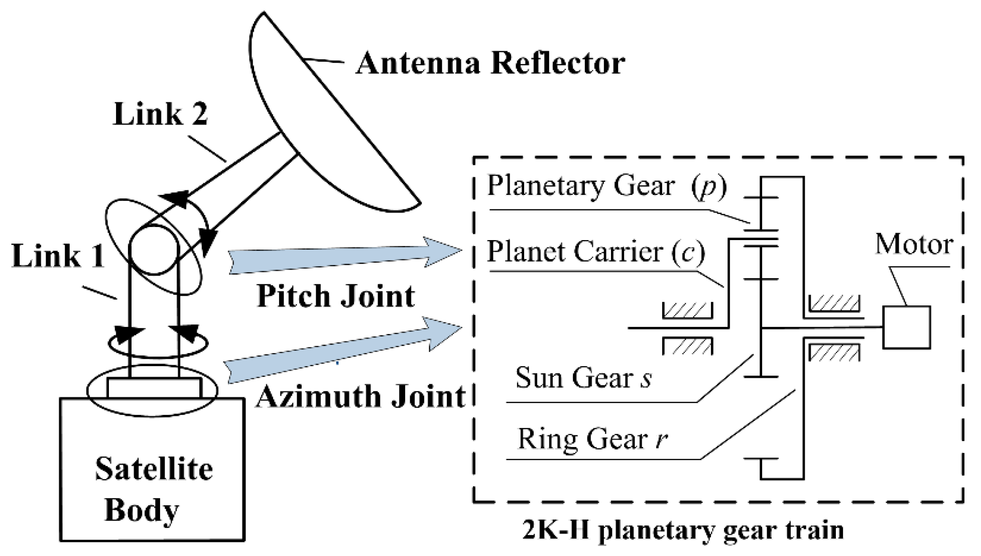
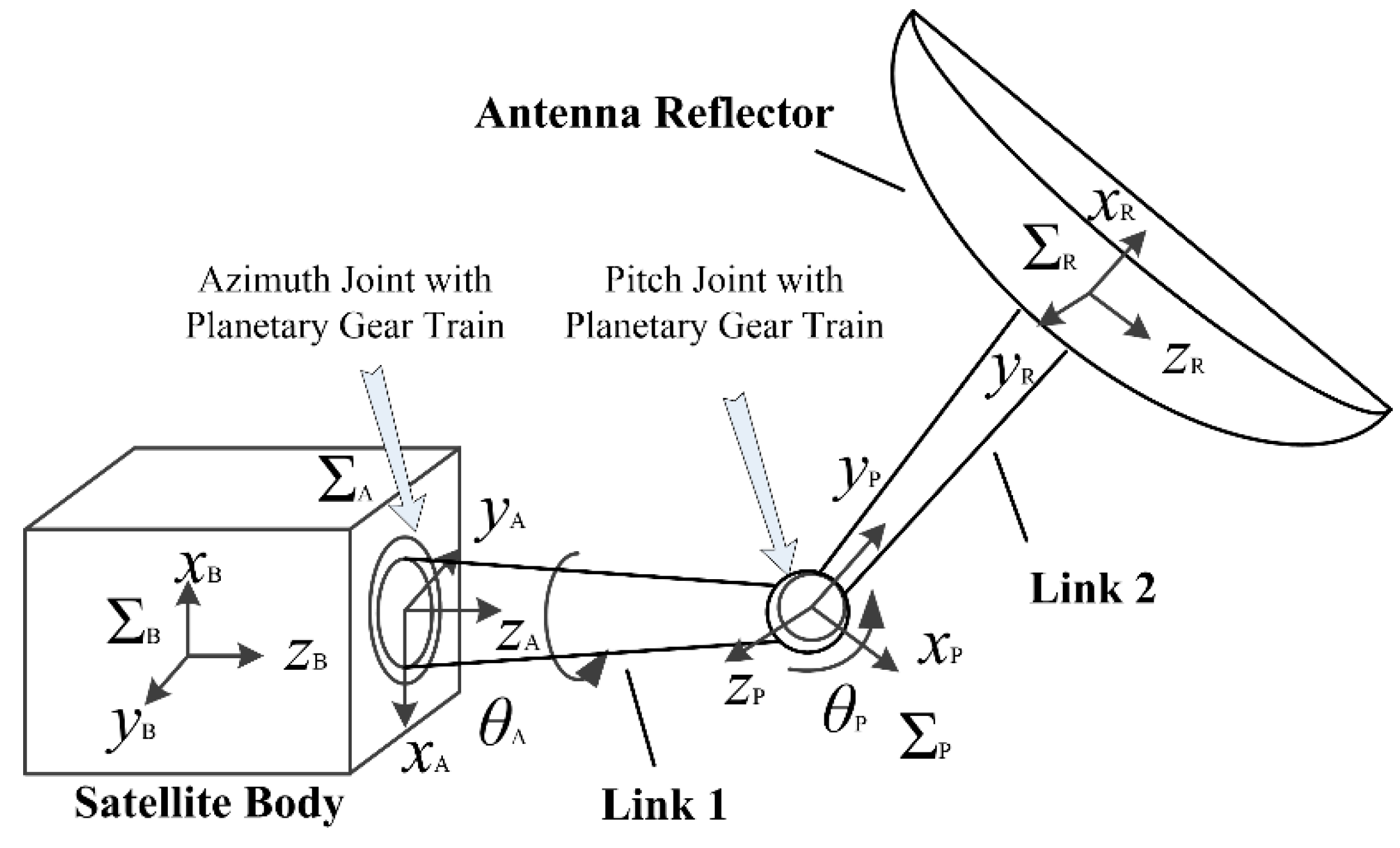
2. Dynamic Model of the Dual-Axis Driving Mechanism for Satellite Antenna with Planetary Gear Joint Considering Multi-Clearance Coupling

2.1. The Simplification of Joints

The dual-axis driving mechanism is a key mechanism to ensure that the satellite antenna can realize functions such as antenna signal receiving and transmitting, real-time tracking, positioning, etc. It has two driving joints—the azimuth joint and the pitch joint. The axes of the two joints are perpendicular to each other, and a planetary gear reducer with the advantages of compact structure, high precision, and large reduction ratio is installed in the joint. However, in the past studies of the dual-axis driving mechanism of the satellite antenna, the joint with the planetary gear reducer was often simplified as an ideal or a planar hinge with clearance, and the nonlinear factors in the joint with planetary gear reducer are ignored, which will result in many unpredictable dynamic response problems of the system.
Yan [43,44] also spotted the problem in his study of a large space manipulator, yet his model only considers the backlash and the radial clearance between the gear shaft and the bearing. Actually, the effect of the multi-clearance coupling on the system cannot be ignored. Therefore, to reveal the effect of the planetary gear joint with a multi-clearance coupling on the dynamic performance of the satellite antenna, the azimuth joint and pitch joint are simplified into the joints of the 2K-H planetary gear reducer, as shown in Figure 1. Five assumptions are made, which are (1) due to the smaller geometric dimensions of link 1 and link 2, the link is considered as rigid bodies; (2) each component in the planetary gear joint is assumed to be rigid, and all gears are assumed to spur gears with involute tooth profiles; (3) the gear is considered to perform plane motion, including the gears rotate around the gear shaft and translation movement at the bearing clearance; (4) the tangential slip at the meshing point of teeth is ignored, this is, tangential friction between teeth is not considered; and (5) the satellite antenna is working in a gravity-free environment, and the effect of gravity is ignored in the model.

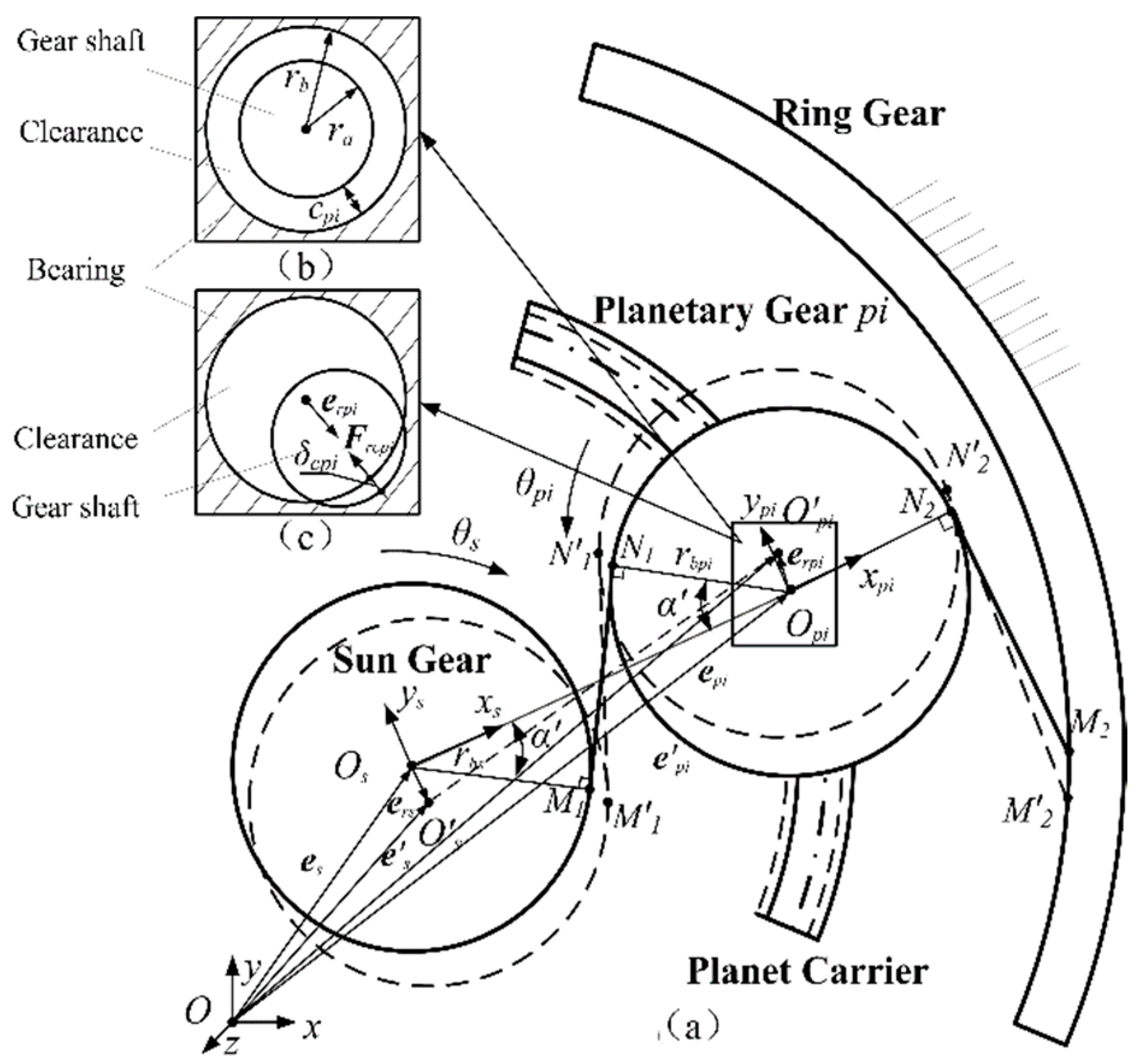
2.2. Contact Force Model of Planetary Gear Pair

In general, the basic unit of power transmission in the 2K-H planetary gear reducer is composed of sun gear, planetary gear, and ring gear. However, the existence of multi-clearance affects these. On the one hand, it causes deviations in their meshing positions, as shown by the dashed lines in Figure 2a, the theoretical meshing line between the sun gear and planetary gear changes from N1M1 to N1M1. Moreover, the theoretical meshing line between the planetary gear and ring gear changes from N2M2 to N2M2, which makes the direction and magnitude of the meshing force change. On the other hand, it caused a collision between the gear shaft and the bearing, resulting in a collision force. Therefore, the key to establish the dynamics model of planetary gear with multi-clearance is to accurately calculate the contact force, including radial collision force and meshing force.

2.2.1. Calculation of the Meshing Force

Due to the existence of radial clearance and backlash in the gear transmission system, the gears engaged in meshing will have certain radial displacement, which will change the meshing position of the gears, causing a change in the dynamic meshing force of the gear. In order to calculate meshing force conveniently, gt is defined as the relative meshing displacement of meshing gear in the direction of the mesh line and the expression is
g t = r s θ s r p i θ p i + ( x s x p i ) sin α + ( y s y p i ) cos α
where r′j (j = s, pi) is the pitch circle radius of the j gear, θs is the angular displacement of the sun gear, and θpi is the angle of planetary gear pi relative to sun guar. xi and yi are the displacement component of the radial displacement of j gear in the X-direction and Y-direction of the global coordinate. αʹ is the actual meshing angle.
According to the geometric characteristics of the gear tooth construction line, the dynamic backlash bt can be expressed as
b t = 2 A 0 cos ( α 0 ) ( i n v ( arccos ( A 0 ( | e p i e s | ) cos ( α 0 ) ) ) i n v ( α 0 ) ) + b 0 + e ( t )
where A0 is the gear standard center distance, b0 is the initial backlash, α0 is the pressure angle of the gear, and e(t) is the tooth profile error, which is time-variant and related to the meshing frequency. It can be described by (Yang [44] and Xiang [46])
e ( t ) = E e sin ( ω m t + φ e )
where ωm is the gear meshing frequency, Ee is comprehensive gear meshing error amplitude, and φe is the initial phase angle of the system.
Due to the coupling between radial clearance and backlash, the change of dynamic backlash is more complicated. In order to judge the contact state between the teeth engaged in meshing, the relative meshing displacement function fg(gt) can be expressed as
f g ( g t ) = { g t g t 0 0 b t < g t < 0 g t + b t g t b t
when gt ≥ 0, the two gears are in drive-side tooth contact with each other and mesh normally. When −bt < gt < 0, there is no contact between the two gears, which leads to tooth detachment. When gt ≤ −bt, back-side tooth contact occurs, that is, the non-driving surface of the driving gear contacts with the driving gear teeth.
In the process of meshing transmission, the dynamic meshing force Ft can be expressed as a function of relative meshing displacement function fg(gt), which includes meshing elasticity force and meshing damping force, and can be expressed as
F t = K t f g ( g t ) + D t [ f g ( g t ) ]
Define the following parameters:
K t = k m [ 1 + ( ε 1 ) cos ( ω m t + φ ) ]
D t = { 2 ξ m ¯ K t f g ( g t ) 0 0       f g ( g t ) = 0
m ¯ = I s I p i r s 2 I s + r p i 2 I p i
where, Kt and km are the time-varying meshing stiffness and the average meshing stiffness, respectively [41]. ε is the contact ratio. ωm defines the gear meshing frequency. φ is the initial phase of variable stiffness. Here, Dt defines the nonlinear damping coefficient. ξ is the damping ratio and set to be 0.06. Equivalent mass m ¯ depends on the gear structure parameters. Ii is the moment of inertia of i (i = s, pi) gear.

2.2.2. Calculation of the Radial Contact Force

First, the radial clearance is defined to accurately calculate the collision between the gear shaft and the bearing. In Figure 3, eri (i = s, pi) represents the displacement vector of the i gear in the radial direction, and it can be calculated as follows:
e r i = e i e i   ( i = s , p i )
To characterize the degree of contact collision between gear shaft and bearing, δ represents the relative penetration depth or deformation between the colliding bodies, and it can be expressed as
δ i = | e r i | c i   ( i = s , p i )
Radial clearance function fr(eri) can be expressed as
f r ( e r i ) = { δ i       | e r i | > c i 0         | e r i | c i   ( i = s , p i )
Due to the cross-sections of the gear shaft and the bearing are circular perpendicular to the axis plane, the collision between them is an orthogonal collision, and the contact force at the collision point is along the normal direction, as shown in Figure 2c. To describe the energy loss caused by internal damping, Lankarani-Nikravesh [8] proposed a new calculation formula based on the Hertz contact model. The normal force is expressed as follows:
F n = K δ n + D δ ˙
where n is the coefficient depends on materials, which is set to 1.5 for metallic material, δ ˙ is the relative penetration velocity, K is the generalized stiffness constant which depends on the geometry and physical properties of the contacting surfaces and is defined by
K = 4 3 π ( σ b + σ a ) R b R a R b R a
where Rb and Ra are the radius of the bearing and the gear shaft, respectively. The material parameters σi (i = b, a) are provided by
σ i = 1 + υ i 2 π E i       ( i = b , a )
where νi and Ei are the Poisson’s ratio and Young’s modulus of the gear shaft and bearing, respectively.
Moreover, the hysteresis damping coefficient D is outlined as
D = 3 K ( 1 c e 2 ) 4 δ ˙ ( ) δ n
where ce is the restitution coefficient, and δ ˙ ( ) is the initial impact velocity.
Although the L–N model has been widely used, it is worth noting that the K value calculated by Equation (13) is a constant value. However, there is a nonlinear relationship between the collision force and the penetration depth. In other words, the K value should not be a constant value, Bai [20,21] defines the nonlinear stiffness coefficient as the slope of the NFD (normal force-displacement) relationship curve near the point of instantaneous deformation base on the Liu model [18], and the expression is represented as
K n = 1 8 ( σ b + σ a ) 2 δ ( 3 ( R b R a ) + 2 δ ) 2 ( R b R a + δ ) 3
Then, they proposed a new nonlinear continuous contact model in the joint clearance, and the expression of the hybrid model is shown in Equation (17) [20,21]
F n m o d = K n δ n + D m o d δ ˙
where Dmod is the modified damping coefficient whether it is high recovery coefficient or low recovery coefficient, and the expression is achieved as follows:
D m o d = 3 K n ( 1 c e 2 ) e 2 ( 1 c e ) 4 δ ˙ ( ) δ n
For the planetary gear pair, there are two states of free motion and contact between components at the radial clearance of bearing, so it is necessary to use radial clearance function fr(eri) to judge the current motion state between shaft and bearing. In this paper, the general expression of radial contact force on planetary gear pair can be expressed as
F r i = K n [ f r ( e r i ) ] n + D m o d [ f r ( e r i ) ] = { δ i 3 2 8 ( σ b + σ a ) 2 δ ( 3 ( R b R a ) + 2 δ ) 2 ( R b R a + δ ) 3 [ 1 + 3 ( 1 c e 2 ) e 2 ( 1 c e ) 4 δ ˙ ( ) δ ˙ i ] | e r i | > c i 0 | e r i | c i       ( i = s , p i )

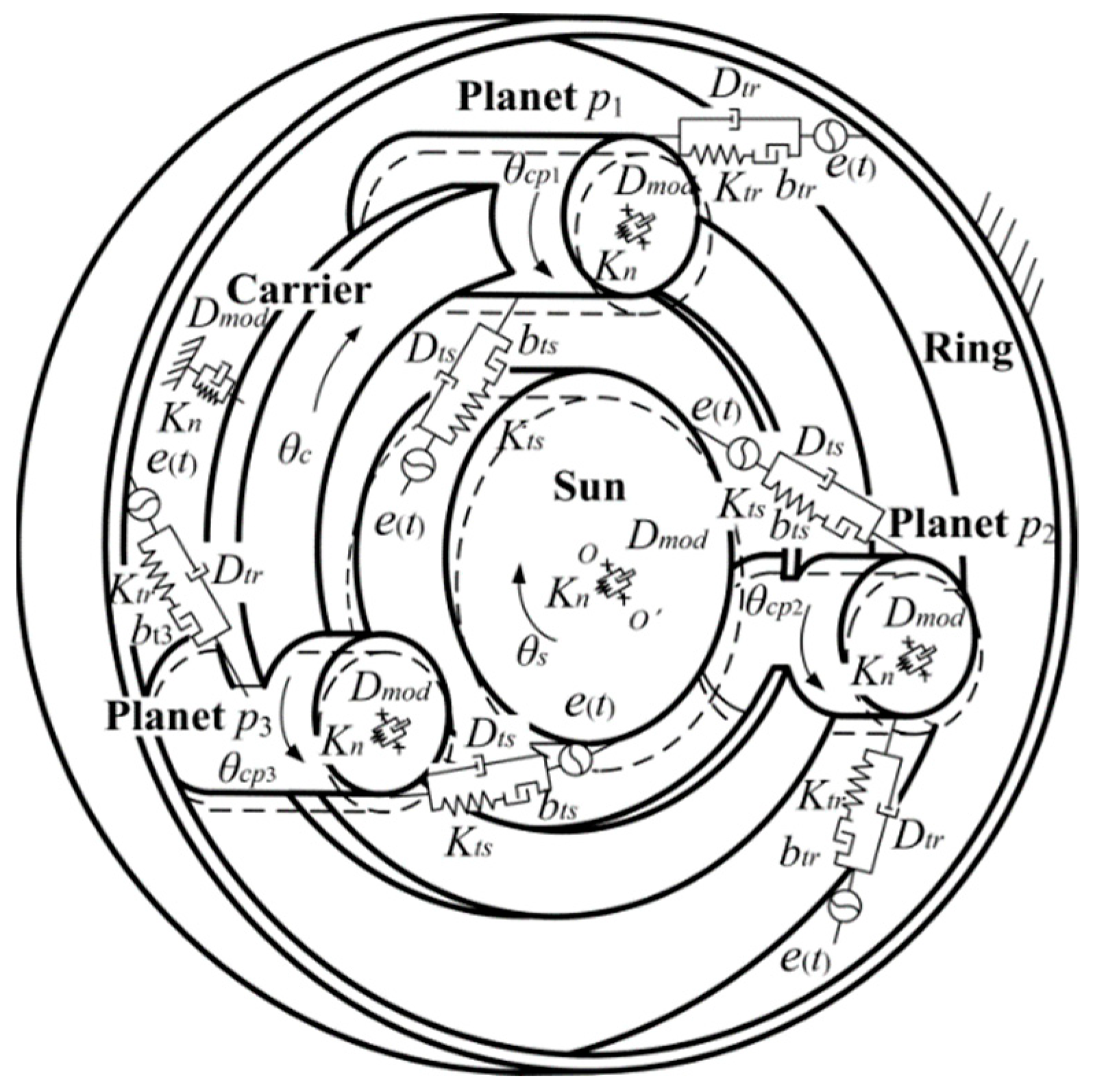
2.3. The Modified Dynamic Model of 2K-H Planetary Gear Joint

The driving joint in the dual-axis driving mechanism is composed of the typical 2K-H planetary gear reducer. In theoretical research, radial clearance and backlash in the 2K-H planetary gear reducer have caused researchers’ attention to the vibration characteristics of the gear system. Zhang [41] proposed a nonlinear dynamic model of planetary gears with multi-clearance coupling by using lumped parameter method. The result shows that the coupling of radial clearance and backlash causes a complex dynamic response of the gear system. However, this model only considers the assembly error and ignores the dynamic change of the backlash caused by the tooth profile error, which leads to major errors in the planetary gear reducer model. In this paper, an improved nonlinear dynamic model of planetary gears with multi-clearance coupling is developed, as shown in Figure 3. The system consists of one sun gear s, one planet carrier c, three planetary gears pi (i = 1, 2, 3), and one ring gear r. Here, the ring gear r is fixed on the frame, the sun gear is the input side, and the planet carrier c is the output side.
In an ideal state, the sun gear, the planetary gears, and the planet carrier only have torsional motion, and their positions are shown by solid lines. However, due to the radial clearance between the gear shaft and the bearing and the backlash between the gear teeth, the position of the sun gear, planet gear, and planet carrier will deviate as shown by the dotted line. On the one hand, this kind of behavior causes the collision force inside the planetary gear, which will cause vibration excitation. On the other hand, it leads to a dynamic change of backlash and meshing force. This will have an adverse effect on the accuracy and stability of the planetary gear joint. In addition, the clearance coupling not only affects the rotation motion of the sun gear, planet carrier, and planetary gear but increases the translational motion along the radial direction.
For the sun gear, its movement can be decomposed into torsional movement and plane movement under the action of driving torque Ts, meshing force Ftspi and radial collision force Frs. The dynamic equation is expressed as follows:
{ I s θ ¨ s + r s i = 1 3 F t s p i = T s m s · [ f r ( e r s ) ] x ( F r s ) x i = 1 3 ( F t s p i ) x = 0 m s [ f r ( e r s ) ] y ( F r s ) y i = 1 3 ( F t s p i ) y = 0
where the radial displacement of the sun gear is denoted by fr(ers), and θs is the angular displacement. (Frs)x and (Frs)y are the components of the radial collision force on sun gear in the X and Y directions, respectively. The mass and moment of inertia of the gears are denoted by ms and Is, rs is the pitch circle radius for the sun gear. (Ftspi)x and (Frspi)y are the components of the meshing force between planetary gear pi and sun gear in the X and Y directions, respectively.
The movement of the planet carrier can be divided into torsional movement around the axis of the sun gear and plane movement. The dynamic equation is expressed as follows:
{ θ ¨ c i = 1 3 [ ( m p i r c 2 ) + I c ]   r s i = 1 3 F t s p i + r r i = 1 3 F t r p i = T c m c [ f r ( e r c ) ] x + ( F r c ) x i = 1 3 ( F r c p i ) x = 0 m c [ f r ( e r c ) ] y + ( F r c ) y i = 1 3 ( F r c p i ) y = 0
where θc is the angular displacement. The mass and moment of inertia of the planet carrier are denoted by mc, Ic. rl (l = s, r) is the pitch circle radius for the l gear. rc is the rotation radius of the planet carrier. Tc denotes torque of the output side. Ftspi is the meshing force between planetary gear pi and sun gear. Ftrpi is the meshing force between planetary gear pi and ring gear. the radial displacement of the planet carrier is denoted by fr(erc). Frc is the radial collision force on planet carrier. (Frcpi)x and (Frcpi)y are the components of the radial collision force between planetary gear pi and planer carrier in the X and Y directions, respectively.
Taking the planet carrier as the reference coordinate, the movement of planetary gear can be decomposed into the torsion around the axis and plane movement at the bearing. The dynamic equation is expressed as follows:
{ θ ¨ c p i I p i + r p i ( F t s p i F t r p i ) = 0 m p i [ f r ( e r c p i ) ] x + ( F r c p i ) x ( F t s p i ) x + ( F t r p i ) x = 0 m p i [ f r ( e r c p i ) ] y + ( F r c p i ) y ( F t s p i ) y + ( F t r p i ) y = 0
where θcpi is the angle of planetary gear pi relative to the planet carrier. The mass and moment of inertia of the gears are denoted by mpi, Ipi. the radial displacement of the planetary gear is denoted by fr(ercpi).
The 2K-H planetary gear reducer in this article contains three pairs of planetary gear pairs, based on the contact force model of planetary gear pair in the previous sec-tion, the modified dynamic model of 2K-H planetary gear joint can be obtained by taking Equations (5) and (19) into Equations (20)–(22). The joint dynamic equation is as follows:
{ I s θ ¨ s + r s i = 1 3 { K t s f g ( g t s p i ) + D t s [ f g ( g t s p i ) ] } = T s m s [ f r ( e r s ) ] x ( K n [ f r ( e r s ) ] x n + D m o d [ f r ( e r s ) ] x ) i = 1 3 { K t s [ f g ( g t s p i ) ] x + D t s [ f g ( g t s p i ) ] x } = 0 m s [ f r ( e r s ) ] y ( K n [ f r ( e r s ) ] y n + D m o d [ f r ( e r s ) ] y ) i = 1 3 { K t s [ f g ( g t s p i ) ] y + D t s [ f g ( g t s p i ) ] y } = 0 θ ¨ c i = 1 3 [ ( m p i r c 2 ) + I c ]   r s i = 1 3 { K t s f g ( g t s p i ) + D t s [ f g ( g t s p i ) ] } + r r i = 1 3 { K t r f g ( g t r p i ) + D t r [ f g ( g t r p i ) ] } = T c m c [ f r ( e r s ) ] x + K n [ f r ( e r s ) ] x n + D m o d [ f r ( e r s ) ] x i = 1 3 { K n [ f r ( e r p i ) ] x n + D m o d [ f r ( e r p i ) ] x } = 0 m c [ f r ( e r s ) ] y + K n [ f r ( e r s ) ] y n + D m o d [ f r ( e r s ) ] y i = 1 3 { K n [ f r ( e r p i ) ] y n + D m o d [ f r ( e r p i ) ] y } = 0 θ ¨ c p i I p i + r p i { K t s f g ( g t s p i ) + D t s [ f g ( g t s p i ) ] K t r f g ( g t r p i ) D t r [ f g ( g t r p i ) ] } = 0 m p i [ f r ( e r c p i ) ] x + K n [ f r ( e r c p i ) ] x n + D m o d [ f r ( e r c p i ) ] x { K t s [ f g ( g t s p i ) ] x + D t s [ f g ( g t s p i ) ] x + K t r [ f g ( g t r p i ) ] x + D t r [ f g ( g t r p i ) ] x } = 0 m p i [ f r ( e r c p i ) ] y + K n [ f r ( e r c p i ) ] y n + D m o d [ f r ( e r c p i ) ] y { K t s [ f g ( g t s p i ) ] y + D t s [ f g ( g t s p i ) ] y + K t r [ f g ( g t r p i ) ] y + D t r [ f g ( g t r p i ) ] y } = 0
where the coefficient n is usually set to 1.5, [ f r ( e r v ) ] u n and f r ( e r v ) ] u (v = s, cpi, c) are defined respectively as the components of radial collision acceleration and radial collision velocity in u (u = X, Y) axis directions. In addition, fg(gtspi) and fg(gtrpi) are defined as the meshing function of the planetary gear with the sun gear and the ring gear.

2.4. System Dynamic Model

Different from the previous model, the driving joint is simplified to a planar hinge with clearance, the 2K-H planetary gear joint is considered in this paper to obtain a more accurate dynamic model of the dual-axis driving mechanism, and the dynamic systems are defined as shown in Figure 4. The system consists of a satellite body, an antenna reflector, two links, an azimuth joint, and a pitch joint, it has two degrees of freedom, and the axes of the two driving joints are crossed.
In general, the dynamic equations established by the Lagrange method are as follows:
{ M q ¨ + C q ˙ + K q + Φ q T λ = F Φ ( q , t ) = 0
where q is a generalized coordinate array, M is a generalized mass matrix of the satellite antenna system, C, and Φ q T are the damping matrix and Jacobian of the constraints, respectively. K is a generalized stiffness matrix, λ refers to the Lagrange Multiplier vector, and F is a generalized external force matrix.
Due to the existence of the clearance in the joint, there is a collision force at the clearance, which causes the problem of the variable topology of the multibody system with clearance. That is, the component adds two degrees of freedom at the clearance. This problem can be solved by using the force constraint equation at the clearance instead of the geometric constraint. That is, the radial collision force is calculated by Equation (19). In addition, the multi-clearance coupling affects the change of the planetary gear meshing force. To consider the influence of the planetary gear joint on the dual-axis driving mechanism, based on the planetary gear joint model with multi-clearance coupling, the equation can be modified as follows:
{ M q ¨ + C q ˙ + K q + Φ q T λ = F + F c Φ ( q , t ) = 0
where Fc is the generalized force matrix that the contact force generated when the gear shaft is in contact with the bearing is converted to the generalized coordinates q.

3. Numerical Simulation and Dynamic Performance Analysis

In this section, the dynamics of the dual-axis driving mechanism of satellite antenna under different driving modes, different rotational speeds, and different clearance coupling are investigated by using the multibody program ADAMS. Here, the driving modes are divided into a single-axis driving mode and a dual-axis driving mode. When only one of the azimuth joint and the pitch joint is driven, it is the single-axis driving mode; when the two joints are driven simultaneously, it is the dual-axis driving mode. The structural parameters of the satellite antenna system and the parameters used in the dynamic simulation are referred to in Bai [45] simulation case, as shown in Table 1 and Table 2.

3.1. Simulations of Dual-Axis Driving Mechanism with Multi-Clearance Coupling in Single-Axis Driving Mode

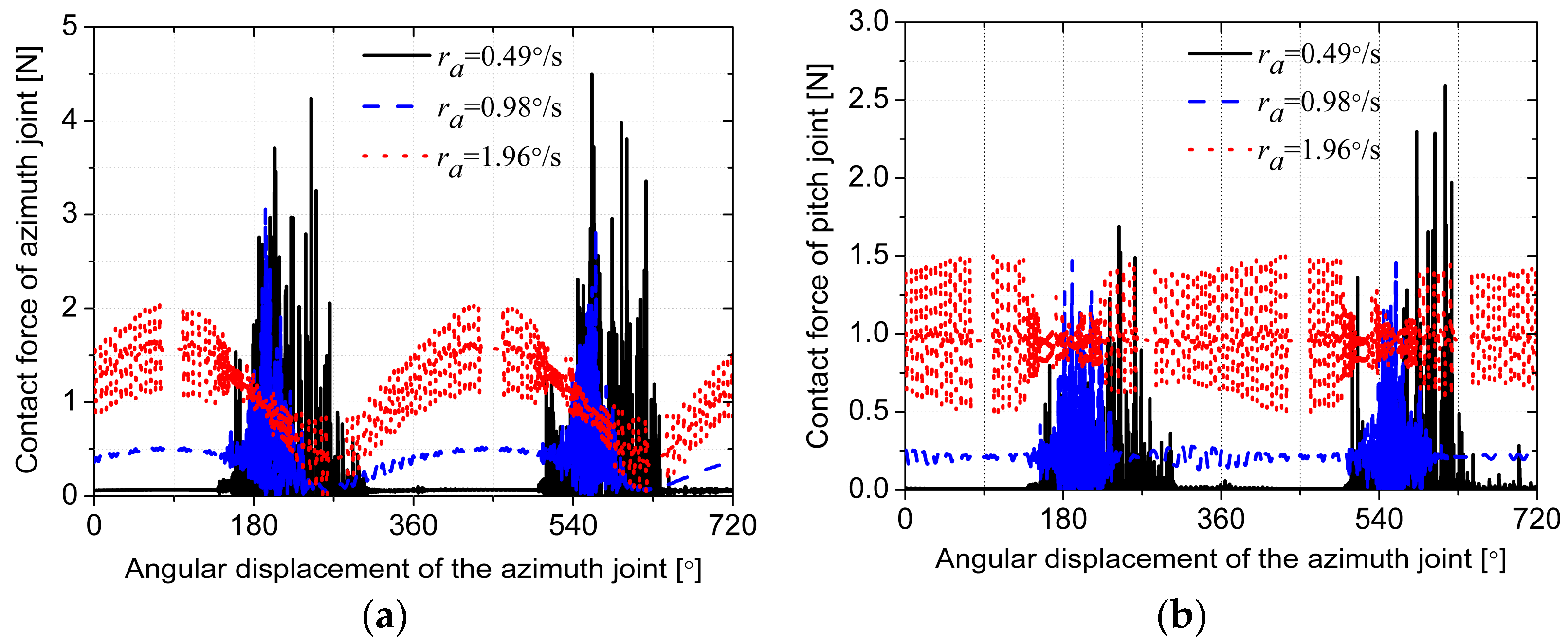
3.1.1. Effects of Rotational Speed

To study the effects of rotational speed on the dynamic performance of the dual-axis driving mechanism for satellite antenna in single-axis driving mode, the rotational speed of single-axis driving adopts three speeds, namely, 0.49°/s, 0.98°/s, and 1.96°/s. The various types of clearance values in the azimuth joint and pitch joint are 100 μm.
Figure 5 shows the radial contact force of the azimuth joint output side and pitch joint output side with a different rotational speed of azimuth joint, the abscissa represents the angular displacement of the azimuth joint, and the ordinate represents the radial contact force. It can be seen that when the rotational speed of the azimuth joint is low, the value of the contact force in the range of 140–300° relative to the initial position has a sudden change in value. However, when the rotational speed is large, the contact force presents continuous change. It can be inferred that when the rotational speed is low, the output shaft of the azimuth joint and the bearing are in a state of alternating contact and separation due to the clearance in the azimuth joint. In addition, when the rotational speed is high, they are in continuous contact mode. Although the pitch joint is relatively static at this time, the collision in the azimuth joint is transmitted to the pitch joint, which will also cause the collision force change in the pitch joint.
When the pitch joint is used as the driving joint in the single-axis driving mode, the radial contact force curves of the azimuth joint and pitch joint are shown in Figure 6. Comparing these two figures, we can find that the amplitude of the contact force increases with the rotational speed, which is similar to the rule in Figure 5. Moreover, the radial contact force of the azimuth joint is greater than the contact force of the pitch joint at the same rotational speed. This is because the inertial load on the azimuth joint is greater, while the load on the pitch joint is only the antenna reflector. In Figure 6a, there is a periodic fluctuation in the radial contact force of the azimuth joint with a certain amplitude, and wave peaks appear at the angular displacements of 0°, 180°, 360°, etc. According to the dual-axis driving mechanism in Figure 1, it can be known that the radial vibration of the azimuth joint in the X direction occurs with the rotation of the pitch joint, and the amplitude of the radial vibration increases with the rotational speed. In Figure 6b, the radial contact force of the pitch joint changes continuously at three rotation speeds, which indicates that the output shaft is in continuous contact mode with the bearing.

3.1.2. Effects of Radial Clearance

To investigate the effects of the coupling between the radial clearances inside the joint in the dual-axis driving mechanism on the system dynamic characteristics, the parameters of each part used in the simulation are shown in Table 3. When the azimuth joint and the pitch joint are respectively used as the driving joint. The change curves of the radial contact force of the output shaft under different radial clearance combinations are shown in Figure 7 and Figure 8.
In Figure 7, when the radial clearance of the planetary gear of the azimuth joint cap is 10 μm, the value of the radial contact force is greatly reduced. The radial contact force is greatly reduced in value, and the curve changes continuously and smoothly, with only small changes, which indicates that the radial clearance of the planetary gear is the main factor that causes the radial contact force of the azimuth joint to change. When the radial clearance of the planet carrier of the azimuth joint cac is 10 μm, the radial contact force does not fluctuate greatly, and there is no small change. That is, the small change in the contact force of the azimuth joint is caused by the radial clearance of the planet carrier. The same law also exists in the pitch joint. Although the radial force curve of the red dot line in Figure 8 fluctuates greatly, it has a long stable period compared with the black solid line and the blue dashed line, which indicates that the radial clearance of the planet carrier in the pitch joint affects small changes in contact force. When the radial clearance of the planet carrier is small, the change of contact force is relatively stable. However, the difference is that the number of peak points of the blue dashed line is more than the other lines. The peak value is large, which shows that when the radial clearance of the planet carrier cpc is 100 μm, and the radial clearance of the planetary gear cpp is 100 μm; the coupling effect between the radial clearance is obvious, which results in a large value of the radial contact force.
From the above analysis, under the special coupling of radial clearance, the radial contact forces of the azimuth joint and the pitch joint fluctuate greatly, which will aggravate the wear and fatigue in the joint. It may cause the radial vibration of the antenna reflector and affect the dynamic pointing accuracy of the satellite. To reveal the effect of radial clearance coupling on the vibration characteristics of the system further, through analysis method of frequency characteristics, the variation law of vibration amplitude of the satellite antenna reflector in the single-axis driving mode is presented, as shown in Figure 9. It can be found that the peak value of the vibration appears for the antenna reflector at a certain radial clearance size; there are four in Figure 9a and three in Figure 9b. The peak point values are listed in Table 4 and Table 5, respectively.
Comparing the two tables, the peak value in Table 4 is smaller than that in Table 5, which indicates that the radial vibration of the azimuth joint attenuates when it is transmitted to the antenna reflector through the pitch joint. However, due to the radial clearance that exists in the pitch joint, the vibration amplitude of the antenna reflector is affected by the coupling of these two joints. In the size of amplitude, the vibration caused by radial clearance of pitch joint is more significant than that caused by azimuth joint.

3.1.3. Effects of Backlash

In the gear mechanism, the existence of the backlash mainly causes the speed error of the transmission joint, and the vibration caused by the meshing collision of the tooth surface also affects the stability of the system. For the dual-axis driving mechanism of the satellite antenna, to investigate the effects of the backlash in the azimuth and pitch joints on the tracking speed error and vibration characteristics of the antenna reflector, the simulation parameters are shown in Table 6.
In Figure 10, the abscissa is the backlash size, and the ordinate is the value of tracking speed error of antenna reflector with different backlash—the solid line of dot-point represents the backlash in the azimuth joint, and the dashed line of square-point represents the backlash in the pitch joint. With the increase of the backlash, the tracking speed error curve caused by the azimuth joint and the pitch joint has a similar rule—when the backlash is 40μm, the tracking speed error is close to zero. However, the amplitude change of tracking speed error caused by pitch joint backlash is large than that caused by azimuth joint backlash. This is because the pitch joint is closer to the satellite reflector than the azimuth joint, and the joint output side error attenuation is smaller.
Similar rules can be obtained from the vibration amplitude curve of the satellite reflector. As shown in Figure 11, the effect of pitch joint backlash on the motion accuracy and stability of the antenna reflector is greater than that of azimuth joint backlash. When the backlash of the azimuth joint is 80 μm, the vibration amplitude of the antenna reflector is small, and compared with the data in Figure 10, the rotational speed error of the antenna reflector is large at this size of backlash, which indicates that the motion accuracy is not necessarily the highest when the antenna reflection is stable. However, when the backlash of the pitch joint is 45 μm, the backlash effect of the pitch joint on the vibration characteristics of the antenna reflector is different from that of the azimuth joint, which is mainly caused by different positions of the pitch joint and the azimuth joint in the system. Therefore, in the design of the dual-axis driving mechanism, the most reasonable design parameters should be carefully selected.

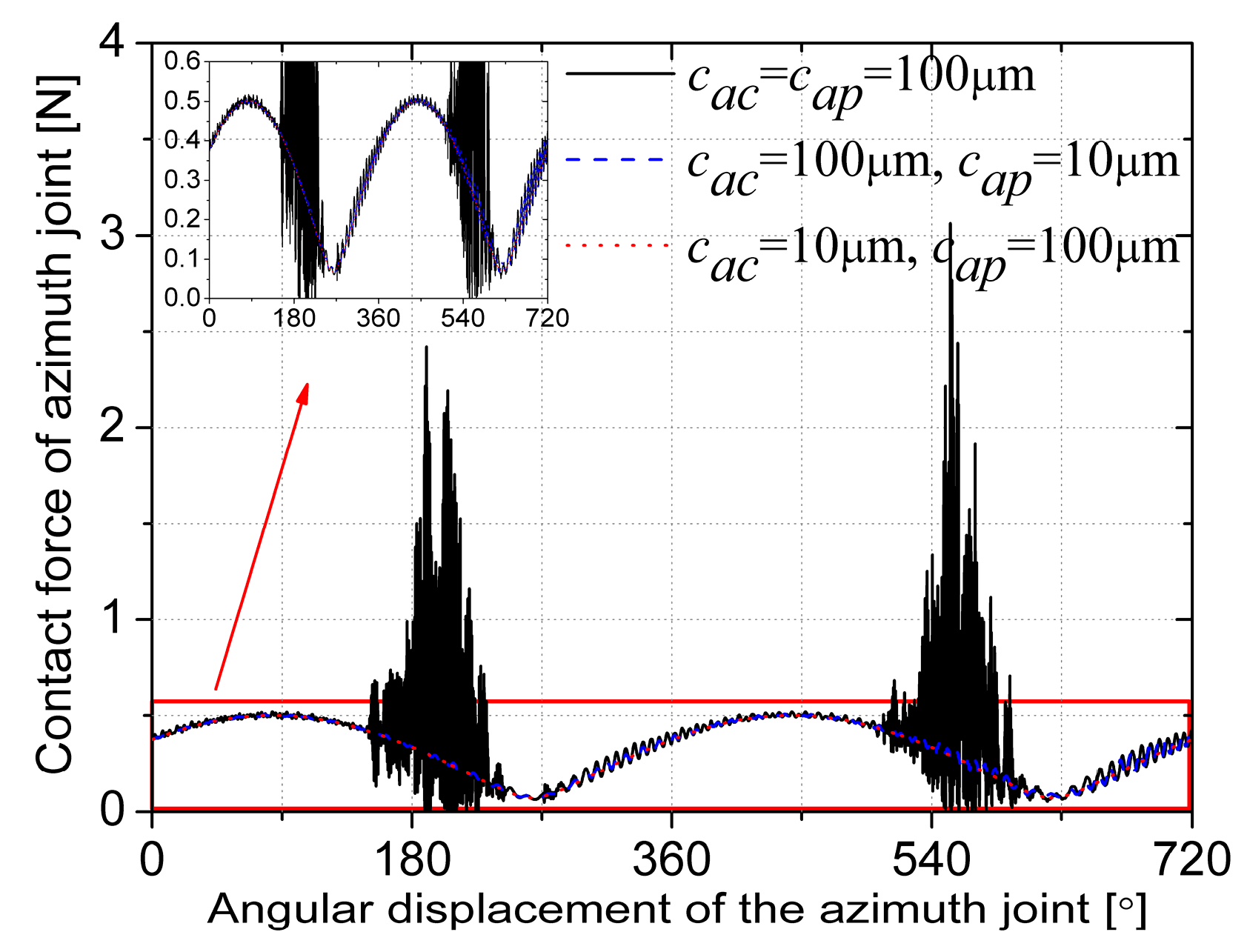
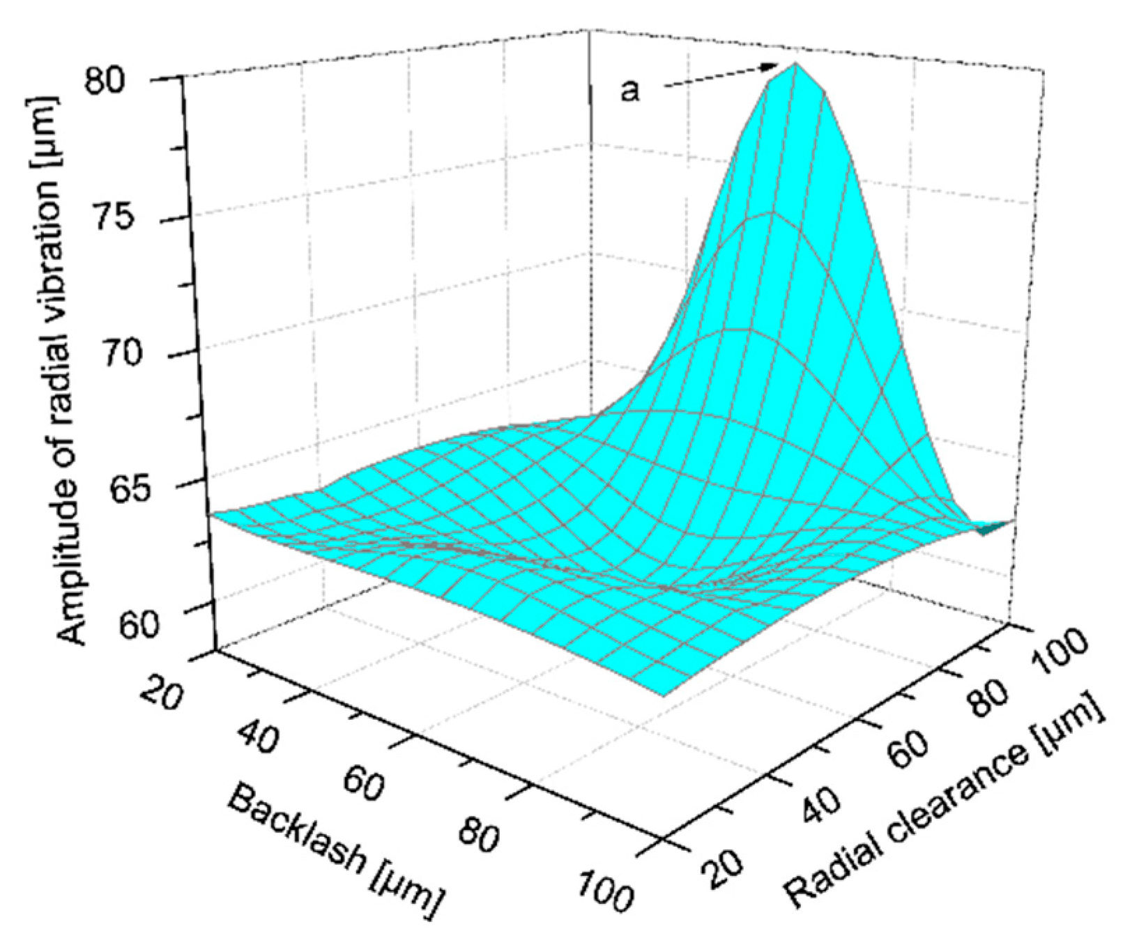
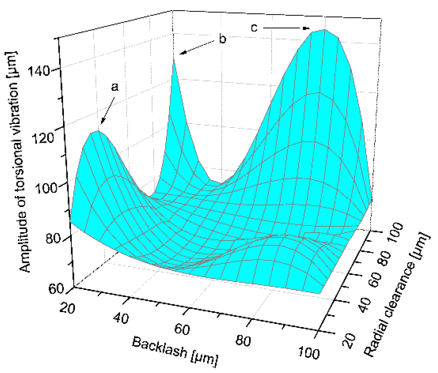
3.1.4. Effects of Coupling between Radial Clearance and Backlash

Planetary gears are the key parts of 2K-H planetary gear reducers. The existence of radial and backlash will have a greater impact on the accuracy of planetary gear transmissions. In the previous section, the effects of the radial clearance and the backlash on the dynamic performances of the system are respectively analyzed. Based on this, the effects of the coupling between radial clearance and backlash in the planetary gear on the dynamic characteristics of the system are investigated in the single-axis driving model. The simulation parameters are shown in Table 7.
Figure 12 and Figure 13 are the tracking speed error of the antenna reflector caused by different coupling between radial clearance and backlash in the azimuth joint and pitch joint. At the three sets of planetary gear clearances in the azimuth joint, the variation trend of the tracking speed error for the antenna reflector is similar, and its value is small. While the tracking speed error caused by the coupling between radial clearance and backlash in the pitch joint fluctuate greatly, the value of tracking speed error is 10 times of that caused by the clearance coupling in the azimuth joint, indicating that the coupling of the clearance in the pitch joint has an obvious effect on the tracking speed error of the antenna reflector. For the radial clearance and backlash of the planetary gears in the pitch joint, the difference of tracking speed error caused by different value combinations is also very obvious, especially the curve fluctuation in Figure 13b,c.
The radial runout curves of the antenna reflector at the different coupling between radial clearances and backlash in planetary gears are analyzed. As shown in Figure 14, whether driving by the azimuth joint or the pitch joint, the radial runout curves of the antenna reflector have similar trends under the respective three sets of clearances. Although the maximum standard deviation of radial runout amplitude caused by the clearance coupling in the azimuth joint is 6.4 μm, which is twice as much as that caused by the pitch joint, but the maximum value of the three back solid curves is close to 112 μm, that is, close to the minimum value of the three dashed lines. So it can be seen that the effect of coupling between radial clearances and backlash in the azimuth joint on the radial runout of the antenna reflector is not obvious. From the comparison of the blue dashed curve in Figure 14a–c, there is a large fluctuation and small vibration in the radial runout of the antenna reflector, and the trend of the curve is consistent. It can be inferred that it is caused by the radial runout of the pitch joint. The small amplitudes of the vibrations in Figure 14b,c are higher than those in Figure 14a, which indicates that there may be resonance in the pitch joint at this clearance combination, resulting in the severe radial runout.
To further reveal the effects of coupling between radial clearance and backlash in the pitch joint on the vibration characteristics of the antenna reflector, the radial and torsional vibration of the antenna reflector caused by the coupling of different gap sizes are analyzed. The results are shown in Figure 15 and Figure 16. The rotational speed of pitch joint rp is 0.98°/s, the radial clearances of planetary gear in pitch joint cpp ranges from 20 μm to 100 μm; the backlash of planetary gear in pitch joint (bpsp and bprp) ranges from 20 μm to 100 μm; other clearances in pitch joint are 10 μm, and all clearances in azimuth joint are 100 μm.
Figure 15 and Figure 16 show that the coupling of radial clearance and backlash of the planetary gears in the pitch joint caused the occurrence of peaks in the radial and torsional vibrations of the antenna reflector, among which the former occurs once and the latter three times. Moreover, the peak point values are shown in Table 8 and Table 9. The antenna reflector at the above resonance point will cause large vibrations, which causes an adverse effect on the dynamic pointing accuracy and operating stability. In the actual design and application, the combination of clearances in the table should be avoided.

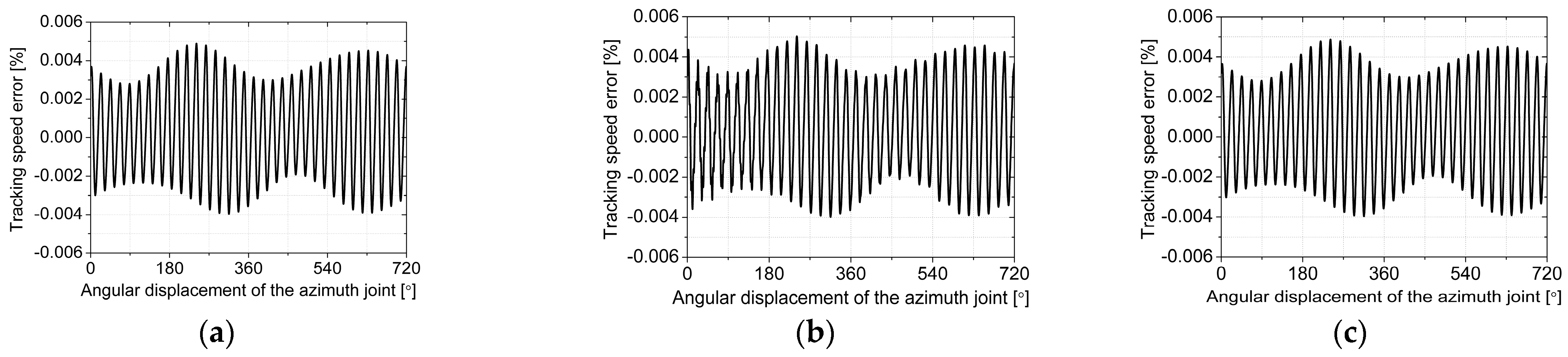
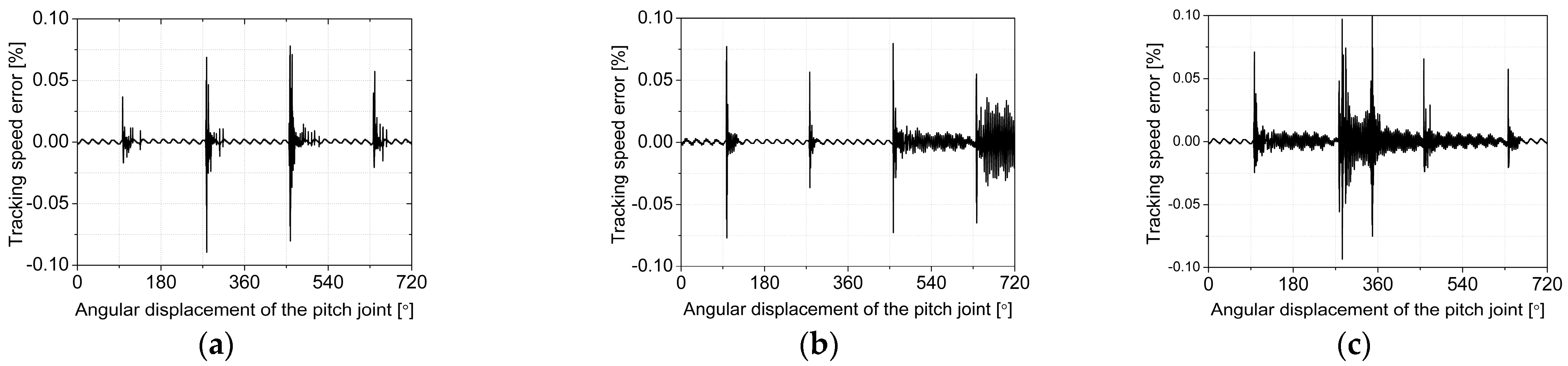
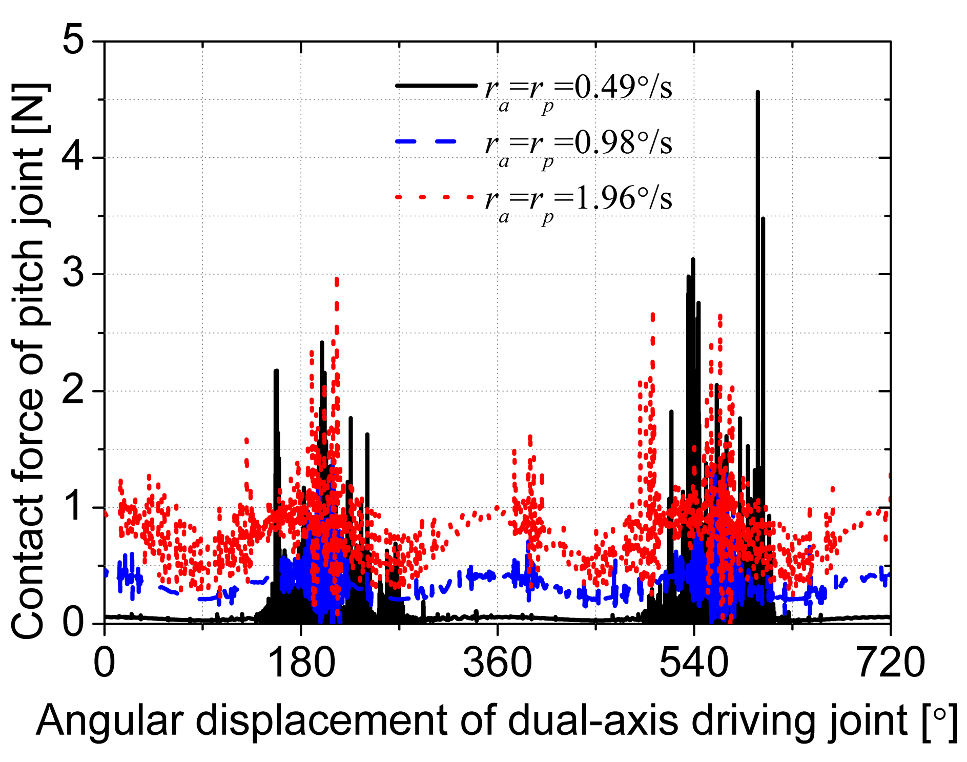
3.2. Simulations of Dual-Axis Driving Mechanism with Multi-Clearance Coupling in Dual-Axis Driving Mode

In previous parts, the dynamic characteristics of the dual-axis driving mechanism for satellite antenna with multi-clearance coupling in the single-axis driving mode were discussed. The results show that the effect is significant. This part will further investigate the coupling effect of rational speed and clearance on system dynamics in dual-axis driving mode. It is assumed that the rational speeds of the azimuth joint and the pitch joint are equal, which are still the typical speed of 0.49°/s, 0.98°/s, 1.96°/s, and all clearances in azimuth and pitch joints are taken as 100 μm; the results are shown in Figure 17, Figure 18 and Figure 19.
Figure 17 and Figure 18 show the change curve of the contact force for the azimuth joint output side and the pitch joint output side with different rotational speeds in the dual-axis driving mode, respectively. It is easy to see that the changing trends of the contact force curves in the two figures are similar at different rotational speeds. The output shaft and bearing change from impact mode to continuous contact mode as the speed increases, the contact force curve tends to be smooth and continuous, and the value also increases. When the rotational speed of the dual-axis is 0.49°/s, the contact force values of the azimuth joint and the pitch joint fluctuate sharply, which is similar to the law in Figure 5a. This indicates that the output shaft and the bearing are in the impact mode, and the collision causes a sharp fluctuation of the contact force. When the rotational speed of the dual-axis is 0.98°/s, the changes of contact force are smoother, and the values are smaller than the rotational speed 1.96°/s, which is conducive to ensuring the reliability of the azimuth joint and the pitch joint and prolonging the service life. Comparing with Figure 5b and Figure 18, although the driving modes are different, both of the change laws of the contact force are similar, which indicates that the contact force of the pitch joint is greatly affected by the azimuth joint. In addition, when the rotational speed is equal, the former is larger than the latter because the former is driven by two joints, and the values are superimposed caused by the rotation of the pitch joint itself. Comparing with Figure 17 and Figure 18, although both the azimuth joint and the pitch joint are composed of planetary gears, the contact force of the azimuth joint is greater than that of the pitch joint due to different positions and loads in the system. It can be inferred that the azimuth joint is more prone to wear or fatigue damage than the pitch joint when the dual-axis driving mechanism of the satellite antenna is in orbit for a long time. Therefore, to improve the overall service life of the satellite antenna system, the pitch joint can be used as much as possible while the use of the azimuth joint can be reduced on the premise of meeting the mission requirements.
Figure 19 shows the component change curve of the position error for antenna reflector in the X, Y, and Z directions at three typical rotational speeds. It can be seen that when the rotational speed is low, the curve fluctuates violently, and when the rotational speed is high, the curve is smooth and continuous, which is consistent with the law in single-axis driving mode. It is also confirmed that the collision at the clearance is more frequent when the rotational speed is low, and when the speed is high, the output shaft and the bearing are in continuous contact mode, the system runs smoothly. It can be derived from curves (a), (b), and (c) in Figure 19 that the component value of position error in the X-direction is larger than that in the other. When combining the structure of the satellite antenna system in Figure 4, we can see the reason for the phenomenon is that the axes of the azimuth and pitch joints are perpendicular to each other, and the radial runout of the two axes is superposed in the X-direction. Furthermore, when the rotational speed is 0.98°/s, the position error in the three directions is relatively small. Therefore, in the case of high requirements for the position accuracy of the antenna reflector, this rotational speed can be selected to reduce the coupling effect of clearance and speed on the motion accuracy of the system.
For the satellite antenna, the dynamic tracking speed of the antenna reflector is also an important performance index. So we studied the coupling effect of rotational speed and clearance on this index. Figure 20 shows the component changing curve of the tracking speed error for antenna reflector in X, Y, and Z directions at three rotational typical speeds. Similar to the position error curve of the antenna reflector, tracking speed error is superimposed in the X-direction, and the value is larger than that in the other two directions. When the rotational speed is 0.98°/s, the curves fluctuate slightly, and the peak value of the error curve does not show a decreasing trend as the rotational speed decreases, indicating that the influence of the rotational speed and clearance coupling on the system is nonlinear. Although the rotational angle of the driving joint whose error value is close to zero in Figure 20a is larger than that in Figure 20b,c, the error in the X-direction fluctuates greatly, which has a greater effect on the tracking speed error of the antenna reflector. As evident from Figure 12, Figure 13 and Figure 20, the reflector tracking speed error in the dual-axis driving mode is larger than in the single-driving mode, which shows that the coupling of joint clearance is more complicated in the dual-axis driving mode and has a greater impact on the accuracy of system control.

4. Conclusions

In this paper, the multi-clearance coupling model of planetary gear pair is established, which solves the conversion problem of the coupling effect between radial clearance and backlash from geometric constraint to collision force constraint. Moreover, the dynamic model of a typical 2K-H planetary gear train with multi-clearance coupling is improved, which considers radial clearance, backlash, tooth profile error, and time-varying meshing stiffness. Based on the above model, the dynamic model of the dual-axis driving mechanism of the satellite antenna with planetary gear joint is developed, which provides a method for analyzing the dynamics of the multibody system with planetary gear joints. Numerical simulation results show that whether in single-axis driving mode or dual-axis driving mode, the rotational speed, radial clearance, backlash, and their coupling have a significant effect on the dynamic pointing accuracy and stability of the system. Several conclusions can be drawn as follows:
  • The coupling effect of the multi-clearance on the dynamic behavior of the dual-axis drive mechanism cannot be ignored. The radial clearance and the backlash in the planetary gear joints have a complex coupling relationship, which is the main factor causing the radial vibration and torsional vibration of the planetary gear joint;
  • In a certain clearance size, the vibration of the planetary gear joint is aggravated, which further affects the stability and accuracy of the dual-axis drive mechanism. Reasonable clearance design can improve the dynamic pointing accuracy and tracking accuracy of the dual-axis driving mechanism, and the analysis data in this article can be used for further reference;
  • The coupling between rotational speed and clearance will cause uncertainty in the dynamic performance of the multibody system. In a certain range, increasing the rotational speed properly can make the joint output shaft and the bearing in a continuous contact mode and make the system run more smoothly, but the contact force also increases, which will increase the joint wear and make the clearance larger in the long-term operation. Higher size of clearance causes greater impact dynamic load and high frequency shakes of the joint, which makes the dynamic performance of the multibody system worse;
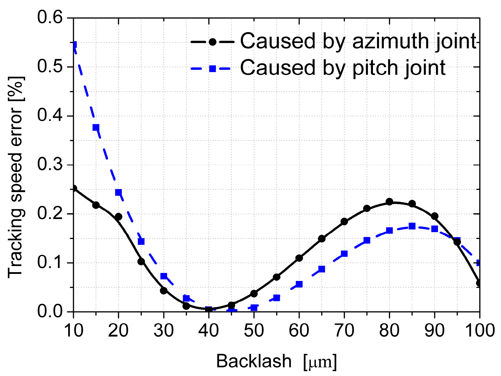
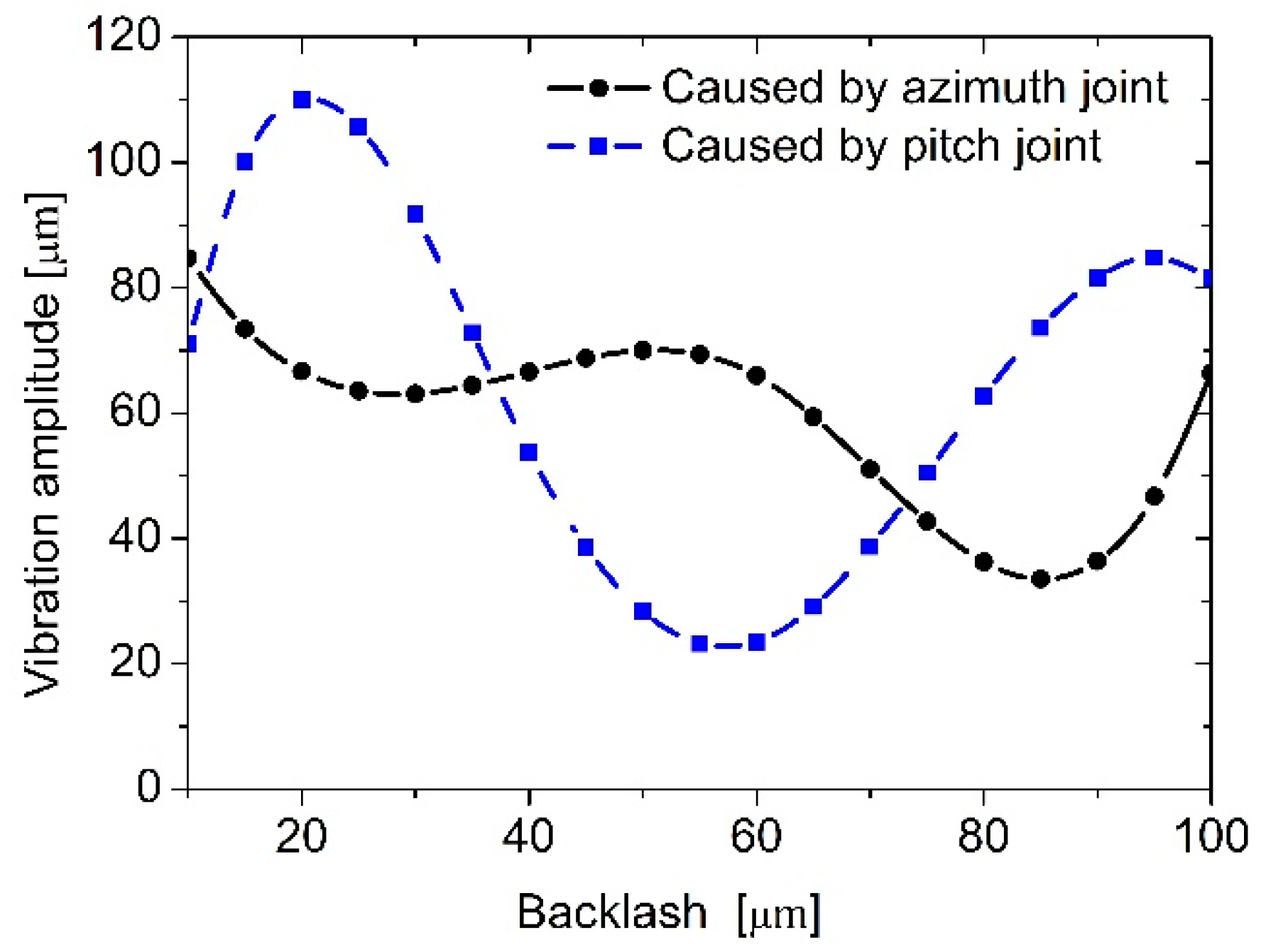
  • For the dual-axis driving mechanism, different positions of planetary gear joints have different effects on the dynamic performance of the system. In addition, the dynamic performance of the joints affects each other, which makes the dynamic performance of the system nonlinear such as the contact force of the pitch joint quite different in both driving modes. Compared with the pitch joint, the azimuth joint has a greater impact on the tracking speed accuracy of the system, while the pitch has a greater impact on the radial and torsional vibration of the system.
Our future work will focus on experimental research on the parameter optimization design of the planetary gear joint for satellite antenna driving mechanism considering multi-clearance coupling.

Author Contributions

Conceptualization, Y.Z.; Data curation, J.H.; Formal analysis, J.H. and L.L.; Funding acquisition, Y.Z.; Investigation, J.H.; Resources, Y.Z.; Validation, L.L. and Y.Z.; Writing—original draft, J.H. and Y.Z.; Writing—review and editing, J.H. All authors have read and agreed to the published version of the manuscript.

Funding

This research was funded by the Natural Science Foundation of Hebei Province of China, grant number E2019202132; the Science and Technology Research Project of Colleges and Universities of Hebei Province, grant number BJ2019049; the Science and Technology on Space Intelligent Control Laboratory, grant number 6142208190308; and the National Key Laboratory of Science and Technology on Vacuum Technology Physics, grant number ZWK1803.

Institutional Review Board Statement

Not applicable.

Informed Consent Statement

Not applicable.

Data Availability Statement

Not applicable.

Conflicts of Interest

The authors declare no conflict of interest.

References

  1. Sun, J.; Ma, X.; Yu, D. Pointing accuracy analyses of a satellitic two-axes antenna pointing mechanism. J. Astronaut. 2007, 28, 545–550. [Google Scholar]
  2. You, B.; Zhang, H.; Li, W.; Zhao, Z.; Chen, J. Dynamic analysis of satellite antenna system with joint clearance and reflector flexibility. J. Aerosp. Eng. 2014, 27, 297–307. [Google Scholar] [CrossRef]
  3. Pan, B.; Zhang, D.; Shi, W.; Lin, T. Modeling and analysis on pointing accuracy of antenna in satellite. Spacecr. Eng. 2011, 20, 49–54. [Google Scholar]
  4. Bai, Z.; Liu, Y.; Sun, Y. Investigation on dynamic responses of dual-axis positioning mechanism for satellite antenna considering joint clearance. J. Mech. Sci. Technol. 2015, 29, 453–460. [Google Scholar] [CrossRef]
  5. Tian, Q.; Flores, P.; Lankarani, H.M. A comprehensive survey of the analytical, numerical and experimental methodologies for dynamics of multibody mechanical systems with clearance or imperfect joints. Mech. Mach. Theory 2018, 122, 1–57. [Google Scholar] [CrossRef]
  6. Alves, J.; Peixinho, N.; da Silva, M.T.; Flores, P.; Lankarani, H.M. A comparative study of the viscoelastic constitutive models for frictionless contact interfaces in solids. Mech. Mach. Theory 2015, 85, 172–188. [Google Scholar] [CrossRef]
  7. Yan, S.; Xiang, W.; Zhang, L. Comprehensive model for 3D revolute joints with clearances in mechanical systems. Nonlinear Dyn. 2015, 80, 309–328. [Google Scholar] [CrossRef]
  8. Lankarani, H.M.; Nikravesh, P.E. Contact force model with hysteresis damping for impact analysis of multibody systems. ASME J. Mech. Des. 1990, 112, 369–376. [Google Scholar] [CrossRef]
  9. Yan, S.; Xiang, W.; Huang, T. Advances in modeling of clearance joints and dynamics of mechanical systems with clearances. Acta Sci. Nat. Univ. Pekin. 2016, 52, 741–755. [Google Scholar]
  10. Flores, P.; Ambrósio, J. Revolute joints with clearance in multibody systems. Comput. Struct. 2004, 82, 1359–1369. [Google Scholar] [CrossRef] [Green Version]
  11. Flores, P.; Ambrósio, J.; Claro, J.C.P.; Lankarani, H.M. Translational joints with clearance in rigid multibody systems. J. Comput. Nonlinear Dyn. 2008, 3, 011007. [Google Scholar] [CrossRef] [Green Version]
  12. Flores, P.; Koshy, C.S.; Lankarani, H.M.; Ambrósio, J.; Claro, J.C.P. Numerical and experimental investigation on multibody systems with revolute clearance joints. Nonlinear Dyn. 2011, 65, 383–398. [Google Scholar] [CrossRef] [Green Version]
  13. Erkaya, S.; Uzmay, B. Investigation on effect of joint clearance on dynamics of four-bar mechanism. Nonlinear Dyn. 2009, 58, 179–198. [Google Scholar] [CrossRef]
  14. Erkaya, S. Trajectory optimization of a walking mechanism having revolute joints with clearance using ANFIS approach. Nonlinear Dyn. 2013, 71, 75–91. [Google Scholar] [CrossRef]
  15. Erkaya, S. Effects of joint clearance on the motion accuracy of robotic manipulators. Stroj. Vestn. J. Mech. Eng. 2018, 64, 82–94. [Google Scholar]
  16. Koshy, C.S.; Flores, P.; Lankarani, H.M. Study of the effect of contact force model on the dynamic response of mechanical systems with dry clearance joints: Computational and experimental approaches. Nonlinear Dyn. 2013, 73, 325–338. [Google Scholar] [CrossRef]
  17. Marques, F.; Isaac, F.; Dourado, N.; Flores, P. An enhanced formulation to model spatial revolute joints with radial and axial clearance. Mech. Mach. Theory 2017, 116, 123–144. [Google Scholar] [CrossRef]
  18. Liu, C.; Zhang, K.; Yang, L. Normal force-displacement relationship of spherical joints with clearances. J. Comput. Nonlinear Dyn. 2006, 1, 160–167. [Google Scholar] [CrossRef]
  19. Liu, C.; Zhang, K.; Yang, L. The FEM analysis and approximate model for cylindrical joints with clearances. Mech. Mach. Theory 2007, 42, 183–197. [Google Scholar] [CrossRef]
  20. Bai, Z.; Zhao, Y. Dynamic behaviour analysis of planar mechanical systems with clearance in revolute joints using a new hybrid contact force model. Int. J. Mech. Sci. 2012, 54, 190–205. [Google Scholar] [CrossRef]
  21. Bai, Z.; Zhao, Y. A hybrid contact force model of revolute joint with clearance for planar mechanical systems. Int. J. Nonlinear Mech. 2013, 48, 15–36. [Google Scholar] [CrossRef]
  22. Tian, Q.; Liu, C.; Machado, M.; Flores, P. A new model for dry and lubricated cylindrical joints with clearance in spatial flexible multibody systems. Nonlinear Dyn. 2011, 64, 25–47. [Google Scholar] [CrossRef]
  23. Liu, C.; Tian, Q.; Hu, H. Dynamics and control of a spatial rigid-flexible multibody system with multiple cylindrical clearance joints. Mech. Mach. Theory 2012, 52, 106–129. [Google Scholar] [CrossRef]
  24. Wang, Z.; Tian, Q.; Hu, H.; Flores, P. Nonlinear dynamics and chaotic control of a flexible multibody system with uncertain joint clearance. Nonlinear Dyn. 2011, 86, 1571–1597. [Google Scholar] [CrossRef]
  25. Li, J.; Huang, H.; Yan, S.; Yang, Y. Kinematic accuracy and dynamic performance of a simple planar space deployable mechanism with joint clearance considering parameter uncertainty. Acta Astronaut. 2017, 136, 34–45. [Google Scholar] [CrossRef]
  26. Herisanu, N.; Marinca, V. An efficient analytical approach to investigate the dynamics of a misaligned multirotor system. Mathematics 2020, 8, 1083. [Google Scholar] [CrossRef]
  27. Fan, W.; Yang, Y.; Su, X. Dynamic modeling and vibration characteristics analysis of transmission process for dual-motor coupling drive system. Symmetry 2020, 12, 1171. [Google Scholar] [CrossRef]
  28. Liu, X.; Wang, J.; Li, W. Dynamic analytical solution of a piezoelectric stack utilized in an actuator and a generator. Appl. Sci. 2018, 8, 1779. [Google Scholar] [CrossRef] [Green Version]
  29. Xu, H.; Qin, D.; Liu, C.; Yi, Y.; Jia, H. Dynamic modeling of multistage gearbox and analysis method of resonance danger path. IEEE Access 2019, 7, 154796–154807. [Google Scholar] [CrossRef]
  30. Kahraman, A.; Singh, R. Non-linear dynamics of a spur gear pair. J. Sound Vib. 1990, 142, 49–75. [Google Scholar] [CrossRef]
  31. Al-shyyab, A.; Kahraman, A. Non-linear dynamic analysis of a multi-mesh gear train using multi-term harmonic balance method: Period-one motions. J. Sound Vib. 2005, 284, 151–172. [Google Scholar] [CrossRef]
  32. Al-shyyab, A.; Kahraman, A. A non-linear dynamic model for planetary gear sets. Proc. Inst. Mech. Eng. Part K J. Mul. 2007, 221, 567–576. [Google Scholar] [CrossRef]
  33. Al-shyyab, A.; Alwidyan, K.; Jawarneh, A.; Tlilan, H. Non-linear dynamic behaviour of compound planetary gear trains: Model formulation and semi-analytical solution. Proc. Inst. Mech. Eng. Part K J. Mul. 2009, 223, 199–210. [Google Scholar] [CrossRef]
  34. Kahraman, A.; Vijayakar, S. Effect of internal gear flexibility on the quasi-static behavior of a planetary gear set. J. Mech. Des. 2001, 123, 408–415. [Google Scholar] [CrossRef]
  35. Tian, Q.; Xiao, Q.; Sun, Y.; Hu, H.; Liu, H.; Flores, P. Coupling dynamics of a geared multibody system supported by ElastoHydroDynamic lubricated cylindrical joints. Multibody Syst. Dyn. 2015, 33, 259–284. [Google Scholar] [CrossRef] [Green Version]
  36. Ambarisha, V.K.; Parker, R.G. Nonlinear dynamics of planetary gears using analytical and finite element models. J. Sound Vib. 2007, 302, 577–595. [Google Scholar] [CrossRef]
  37. Bahk, C.J.; Parker, R.G. Analytical solution for the nonlinear dynamics of planetary gears. J. Comput. Nonlinear Dyn. 2011, 6, 21007. [Google Scholar] [CrossRef]
  38. Bahk, C.J.; Parker, R.G. Analytical investigation of tooth profile modification effects on planetary gear dynamics. Mech. Mach. Theory 2013, 70, 298–319. [Google Scholar] [CrossRef]
  39. Cooley, C.G.; Parker, R.G. A frequency domain finite element approach for three-dimensional gear dynamics. J. Vib. Acoust. 2011, 133, 41004. [Google Scholar] [CrossRef]
  40. Li, X.; You, B.; Zhang, H.; Zhao, Y. Dynamic analysis of gear-rotor system coupled with radial clearance and dynamic backlash. J. Vib. Eng. Technol. 2016, 4, 271–281. [Google Scholar]
  41. Zhang, H.; Qi, C.; Fan, J.; Dai, S.; You, B. Vibration characteristics analysis of planetary gears with a multi-clearance coupling in space mechanism. Energies 2018, 11, 2687. [Google Scholar] [CrossRef] [Green Version]
  42. Wei, J.; Zhang, A.; Qin, D.; Lim, T.C.; Shu, R.; Lin, X.; Meng, F. A coupling dynamics analysis method for a multistage planetary gear system. Mech. Mach. Theory 2017, 110, 27–49. [Google Scholar] [CrossRef]
  43. Yang, T.; Yan, S.; Han, Z. Nonlinear model of space manipulator joint considering time-variant stiffness and backlash. J. Sound Vib. 2015, 341, 246–259. [Google Scholar] [CrossRef]
  44. Yang, T.; Yan, S.; Ma, W.; Han, Z. Joint dynamic analysis of space manipulator with planetary gear train transmission. Robotica 2016, 34, 1042–1058. [Google Scholar] [CrossRef]
  45. Bai, Z.; Zhao, J.; Chen, J.; Zhao, Y. Design optimization of dual-axis driving mechanism for satellite antenna with two planar revolute clearance joints. Acta Astronaut. 2018, 144, 80–89. [Google Scholar] [CrossRef]
  46. Xiang, L.; Zhang, Y.; Gao, N.; Hu, A.J. Nonlinear dynamics of a multistage gear transmission system with multi-clearance. Int. J. Bifurc. Chaos 2018, 28, 1850034. [Google Scholar] [CrossRef]
Figure 1. Simplification of the dual-axis driving mechanism for satellite antenna.
Energies 14 00815 g001
Figure 2. (a) Schematic representation of a planetary gear pair with clearance (clearance exaggerated for clarity); (b) gear pair with radial clearance and free movement; and (c) penetration depth between the gear shaft and bearing during impact.
Energies 14 00815 g002
Figure 3. The simplified model of 2K-H planetary gear with multi-clearance coupling.
Energies 14 00815 g003
Figure 4. The dynamic model of the satellite antenna system.
Energies 14 00815 g004
Figure 5. Radial contact force with a different rotational speed of azimuth joint—(a) radial contact force of azimuth joint output side and (b) radial contact force of pitch joint output side.
Energies 14 00815 g005
Figure 6. Radial contact force with a different rotational speed of pitch joint—(a) radial contact force of azimuth joint output side and (b) radial contact force of pitch joint output side.
Energies 14 00815 g006
Figure 7. The radial contact force of azimuth joint with different radial clearance.
Energies 14 00815 g007
Figure 8. The radial contact force of pitch joint with different radial clearance.
Energies 14 00815 g008
Figure 9. The amplitude of radial vibration for antenna reflector with different radial clearance combinations (a) caused by radial clearance coupling in the azimuth joint and (b) caused by radial clearance coupling in the pitch joint.
Energies 14 00815 g009
Figure 10. Tracking speed error of the antenna reflector with different backlashes—the solid line of dot-point represents the backlash in the azimuth joint; the dashed line of square-point represents the backlash in the pitch joint.
Energies 14 00815 g010
Figure 11. Vibration amplitude of antenna reflector with different backlashes—the solid line of dot-point represents the backlash in the azimuth joint; the dashed line of square-point represents the backlash in the pitch joint.
Energies 14 00815 g011
Figure 12. Tracking speed error of antenna reflector caused by different clearance size of planetary gear in azimuth joint: (a) cap = 100 μm, basp = barp = 100 μm; (b) cap = 100 μm, basp = barp = 10 μm; and (c) cap = 10 μm, basp = barp = 100 μm.
Energies 14 00815 g012
Figure 13. Tracking speed error of antenna reflector caused by different clearance size of planetary gear in pitch joint: (a) cpp = 100 μm, bpsp = bprp = 100 μm; (b) cpp = 100 μm, bpsp = bprp = 10 μm; and (c) cpp = 10 μm, bpsp = bprp = 100 μm.
Energies 14 00815 g013
Figure 14. Radial runout of antenna reflector caused by different clearance size of planetary gear—the back solid line represents changing the clearance size in the azimuth joint; the blue dashed line represents changing the clearance size in the pitch joint; (a) cip = 100 μm, bisp = birp = 100 μm; (b) cip = 100 μm, bisp = birp = 10 μm; and (c) cip = 10 μm, bisp = birp = 100 μm (i = p,a).
Energies 14 00815 g014
Figure 15. The amplitude of radial vibration for antenna reflector with different clearance size of planetary gear in pitch joint.
Energies 14 00815 g015
Figure 16. The amplitude of torsional vibration for antenna reflector with different clearance size of planetary gear in pitch joint.
Energies 14 00815 g016
Figure 17. The radial contact force of azimuth joint output side with different rotational speeds.
Energies 14 00815 g017
Figure 18. The radial contact force of pitch joint output side with different rotational speeds.
Energies 14 00815 g018
Figure 19. Position error of antenna reflector with different rotational speeds in dual-axis driving mode: (a) component change in X-direction; (b) component change in Y-direction; and (c) component change in Z-direction.
Energies 14 00815 g019
Figure 20. Tracking speed error of the antenna reflector with different rotational speeds in dual-axis driving mode: (a) component change in X-direction; (b) component change in Y-direction; and (c) component change in Z-direction.
Energies 14 00815 g020
Table 1. Structural parameters of the satellite antenna system.
Rigid BodyMass/kgIxx/kg·m2Iyy/kg·m2Izz/kg·m2
Spacecraft body1500210017002400
Azimuth joint3.770.115450.115450.004712
Pitch joint3.770.115450.115450.004712
Antenna reflector8.0050.682971.059560.68297
Table 2. Parameters used in the dynamic simulation.
ParameterValue
Driving moment of the azimuth axis, Ta (N·m)1.5 cos (2 πt)
Driving moment of the pitch axis, Tp (N·m)0.8 cos (2 πt)
Contact stiffness coefficient, K (N/m)1 × 107
Damping coefficient, D (Ns/m)100
Step size (s)0.0001
Table 3. Simulation parameters of radial clearance.
Driving JointNon-Driving JoinBacklash of Driving JointRadial Clearance of Driving Joint
Azimuth joint, and ra = 0.98°/sPitch joint, and cp = 100 μmba = 10 μm(a) cac= cap = 100 μm
(b) cac = 100 μm, cap =10 μm
(c) cac = 10 μm, cap =100 μm
Pitch joint, and rp = 0.98°/sAzimuth joint, and ca = 100 μmbp = 10 μm(a) cpc= cpp = 100 μm
(b) cpc =100 μm, cpp =10 μm
(c) cpc =10 μm, cpp =100 μm
Table 4. The peak value of radial vibration for antenna reflector in Figure 9a.
Peak PointRadial Clearance of Planet Carrier cac (μm)Radial Clearance of Planetary Gear cap (μm)Vibration Amplitude
(μm)
a3510019.5
b403520
c1003022.5
d10010021
Table 5. The peak value radial vibration for antenna reflector in Figure 9b.
Peak PointRadial Clearance of Planet Carrier cpc (μm)Radial Clearance of Planetary Gear cpp (μm)Vibration Amplitude
(μm)
a858575
b2085125
c353556
Table 6. Simulation parameters of backlash.
Driving JointNon-Driving JointRadial Clearance of Driving JointBacklash of Driving Joint
Azimuth joint, and ra = 0.98°/sPitch joint, and cp = 100 μmcac = cap = 10 μmba = 10–100 μm
Pitch joint, and rp = 0.98°/sAzimuth joint, and ca = 100 μmcpc = cpp = 10 μmbp = 10–100 μm
Table 7. Simulation parameters of coupling between radial clearance and backlash.
Driving JointNon-Driving JointRadial Clearance of Driving JointBacklash of
Driving Joint
Other Clearance of Driving
Azimuth joint, and ra = 0.98°/sPitch joint, and cp = 100 μm(a) cap = 100 μm,(a) basp = barp = 100 μm;10 μm
(b) cap = 100 μm,(b) basp = barp = 10 μm;
(c) cap = 10 μm,(c) basp = barp = 100 μm
Pitch joint, and rp = 0.98°/sAzimuth joint, and ca = 100 μm(a) cpp = 100 μm,(a) bpsp = bprp = 100 μm;10 μm
(b) cpp = 100 μm,(b) bpsp = bprp = 10 μm;
(c) cpp = 10 μm,(c) bpsp = bprp = 100 μm
Table 8. The peak value of radial vibration for antenna reflector in Figure 15.
Peak PointRadial Clearance of Planetary Gear cpp (μm)Backlash of Planetary Gear bpsp and bprp (μm)Vibration Amplitude
(μm)
a1003078.5
Table 9. The peak value of torsional vibration for antenna reflector in Figure 16.
Peak PointRadial Clearance of Planetary Gear cpp (μm)Backlash of Planetary Gear bpsp and bprp (μm)Vibration Amplitude
(μm)
a4020112
b10020130
c10080145
Publisher’s Note: MDPI stays neutral with regard to jurisdictional claims in published maps and institutional affiliations.

