Abstract
The traditional bearingless synchronous reluctance motor (BSynRM) with salient pole rotor has some drawbacks such as high suspension force ripple, low torque density and low power factor. To overcome the above shortcomings, the permanent-magnet-assisted bearingless synchronous reluctance motor (PMa-BSynRM) is proposed. In this paper, two types of PMa-BSynRM rotors with the same number of permanent magnets but different magnetic barrier structures are designed. A traditional BSynRM with a salient pole rotor is introduced, and the electromagnetic and vibration characteristics of the three BSynRM are analyzed and compared. Firstly, the rotor structures of the two PMa-BSynRMs are designed, and the operation principle of the BSynRM is introduced. Secondly, electromagnetic characteristics of the three motors are analyzed and compared in detail using FEA software. Thirdly, the vibration analysis of the three motors is carried out. Finally, the experimental prototype platforms are built. The FEA and experimental results verify that the designed PMa-BSynRM can improve the power factor and torque density of traditional BSynRMs, and the most superior BSynRM among the three is identified.
1. Introduction
Magnetic bearing technology has the advantages of no friction, no wear, high speed, high precision, long life and so on. It is an ingenious solution to the friction and wear problems of mechanical bearings [1,2]. However, the shortcomings of long axial length, relatively complicated structure and control, and high cost, have made it difficult to combine electric motors and magnetic bearings to achieve a high power factor, which limits the application range of magnetic bearings [3,4].
Through installing a set of suspension force windings in the stator of the motor, a bearingless motor can solve these disadvantages effectively. By inheriting the advantages of magnetic bearings and higher significance ratio of synchronous reluctance motors (SynRMs), the bearingless synchronous reluctance motors (BSynRMs) achieve many advantages, such as simple structure, low cost, and low loss. So the BSynRM is suitable for vacuum and ultra-clean environments, high-precision applications and many other industrial fields [5,6]. Due to the fact that bearingless motors have the characteristics of no friction, no wear and low mechanical loss, they are suitable for use as a drive motor in a flywheel energy storage system.
In recent years, several studies on the BSynRM structure have been hot topics. The primary structure of the 24-stator-slot/4-rotor-pole BSynRM with the salient rotor was first proposed and designed in detail in [7]. According to [8], efficient radial force production can be realized using an appropriate motor exciting current. In [9], the suspension force produced by the bearingless permanent magnet synchronous motor, bearingless induction motor and BSynRM is compared and analyzed, respectively. An increase in torque density and an apparent decrease in the coupling between the suspension force and the current of torque windings was reported in [10] because the multi-layer flux barriers rotor is selected in the BSynRM. In [11], the electromagnetic characteristics of the BSynRM with the flux barriers rotor were analyzed. In [12], a new rotor structure with multilayer flux barrier of the BSRM is proposed to improve electromagnetic performances. According to [10,11,12], although the power factor and torque density of the BSynRM with the flux barriers rotor were improved, compared with the salient rotor, they were still lower than that of the rare earth permanent magnet motor. In [13], a permanent-magnet-assisted BSynRM was designed to overcome the drawbacks of low torque density and power factor. The resulting configuration is called PM-assisted BSynRM.
PM-assisted SynRMs have become a research hotspot in recent years. PM-assisted SynRM was first proposed by the Italian scholar A. Vagati. Due to the limitations of the technology and materials at that time, PM-assisted SynRM failed to achieve further development for a long time thereafter [14]. Then, as the advantages of PM-assisted SynRM such as large speed adjusting range, high power density and cost-effectives have been deeply explored, it has gained more and more attention, particularly in applications requiring high torque density and compact space, such as electric vehicles, aerospace, agricultural production, and medical equipment [15,16]. At present, there are many published studies on PM-assisted SynRM; in particular, many methods have been proposed to solve the problem of large torque ripple. In order to obtain the optimal rotor geometry, a novel method to evaluate the sensitivity of the torque ripple over the entire design space has been presented [17]. In [18], the optimal design for the stator pole/slot combination, winding method, and stator parameter design are proposed to improve the efficiency and reduce the torque ripple of the PMa-SynRM. In [19], a five-phase bearingless permanent-magnet-assisted synchronous reluctance machine for high-speed applications is proposed. In [20], a permanent-magnet-assisted single winding bearingless synchronous reluctance motor with a T-shaped winding structure is proposed. However, in [19,20], the different installation position of the permanent magnet is not taken into account. Because of the requirements of the different application areas, such as aeronautics and astronautics and turbomolecular pumps, the prediction of the motor vibration is necessary.
Two PMa-BSynRMs are designed in this paper, and a comparative analysis between them and a salient pole BSynRM is carried out. The quantities of permanent magnets of the two motors PMa-BSynRMs are the same, and their difference lies in the different flux barrier structures and permanent magnet installation positions. The torque performance and suspension force performance of the motors are carried out by finite element analysis (FEA), as well as their vibration characteristics. After comprehensively considering the above performances, the optimal motor is selected, and the experimental research of the prototype is carried out.
Two rotors of PMa-BSynRMs and BSynRM with the same number of permanent magnets but different shapes of magnetic barrier are designed in this paper. Firstly, the structure and operation principles of the two PMa-BSynRMs are introduced in Section 2. In Section 3, the electromagnetic characteristics of the two PMa-BSynRMs and BSynRM are analyzed and compared in detail through finite element analysis (FEA). Then, in Section 4, the vibrations of PMa-BSynRMs and BSynRM are discussed and compared based on the model analysis and harmonics of the radial force. In Section 5, the experimental prototype platform is built and the FEA results are verified experimentally. Finally, in Section 6, the conclusion is drawn based on the above analysis.
2. PMa-BSynRMs Topologies and Operation Principles
2.1. Motor Structures
The cross-sections of the two designed 24-stator-slot/4-rotor-pole PMa-BSynRMs and a normal BSynRM are depicted in Figure 1. Except for the rotors, the stator structure and the size of the three motors are the same. The total number of permanent magnets in the two designed PMa-BSynRMs are the same, and their cross-sectional area is 36 × 3 mm2. Their main dimensions and specifications are listed in Table 1.
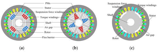
Figure 1.
Cross-sections of motors with different rotors. (a) permanent-magnet-assisted bearingless synchronous reluctance motor I (PMa-BSynRM I); (b) PMa-BSynRM II; (c) bearingless synchronous reluctance motor (BSynRM).

Table 1.
Main Motor Specifications (adapted from [13]).
The stator windings are composed of torque windings and suspension force windings, which are arranged with three-phase chain windings and three-phase concentric windings, respectively. The structure is shown in Figure 2.
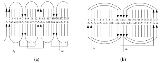
Figure 2.
A phase winding schematic diagram of motors. (a) Torque Windings; (b) suspension force windings.
Flux barrier rotors are applied in both PMa-BSynRMs, and the permanent magnets are installed. Based on the different flux barrier structure and installation position of the permanent magnets, the two PMa-BSynRMs are named PMa-BSynRM I and PMa-BSynRM II, respectively.
As illustrated in Figure 3, the left end of the rotor is fixed in the axial- and radial-direction by a self-aligning ball bearing. The right end is supported by an auxiliary bearing, and the auxiliary mechanical bearing clearance between the auxiliary bearing and the shaft is a 0.5 mm. Therefore, the suspension of the rotor with two degrees of freedom in the radial direction is realized.
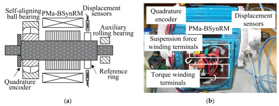
Figure 3.
PMa-BSynRM experimental prototype. (a) Structural sketch map; (b) physical map.
2.2. Operation Principles and Mathematical Model
The reluctance torque generation principle of the PMa-BSynRM is the same as that of the traditional synchronous reluctance motor. The difference between d- and q-axis magnetic reluctance limit the PMa-BSynRM to operate at synchronous speed, as shown in Figure 4.
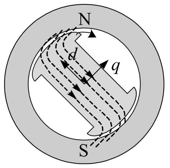
Figure 4.
Diagram of reluctance torque generation principle.
Similar to the traditional synchronous reluctance motor, the PMa-BSynRM also needs to increase the difference between d- and q-axis inductance to produce higher reluctance torque. Because permanent magnets are installed in the rotor, the torque produced by the permanent magnet is also included in the total torque.
Figure 5 shows that the d- and q-axis flux path of two PMa-BSynRMs is different due to different mounting positions and magnetization directions, which lead to the different electromagnetic properties observed for two PMa-BSynRMs.
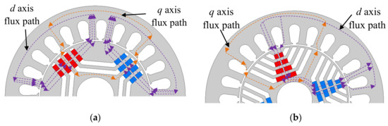
Figure 5.
Flux path of proposed PMa-BSynRMs. (a) PMa-BSynRM I; (b) PMa-BSynRM II.
The torque expression of the motor is derived by the virtual displacement method, which is expressed as
where i0 is equivalent excitation current of permanent magnet, LMMd is mutual inductance between stator and rotor in the d-axis, γ is the angle between the current vector and d-axis. Compared with the traditional BSynRM, the use of a permanent magnet increases the torque density of PMa-BSynRM and increases its speed performance.
According to the torque mathematical model of the PMa-BSynRM, the vector diagram is drawn as Figure 6. Because of the existence of a permanent magnet, the angle between the voltage and current vectors is reduced, and the power factor of PMSM is improved.
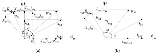
Figure 6.
Torque subsystem vector diagrams. (a) PMa-BSynRM; (b) BSynRM.
As shown in Figure 7, the principle of the radial suspension force generation of a BSynRM with a salient pole rotor is introduced. According to the magnetic field equivalent current analysis method, NM and NB represent equivalent torque windings and equivalent suspension force windings, respectively. If the current of NB is zero, the flux densities at the air gap of the pole numbered 1, 2, 3 and 4 are equal to each other. When there is a suspension force current in NB, a two pole flux ψB is produced. Then, the flux densities of each pole will not be equal. The flux density at pole 1 decreases, while at pole 3 increases, and the radial suspension force Fy is applied on the rotor. According to [10], the generation principle of the suspension force of the BSynRM with a multi-flux barrier construction is the same as the conventional BSynRM with the salient pole rotor.
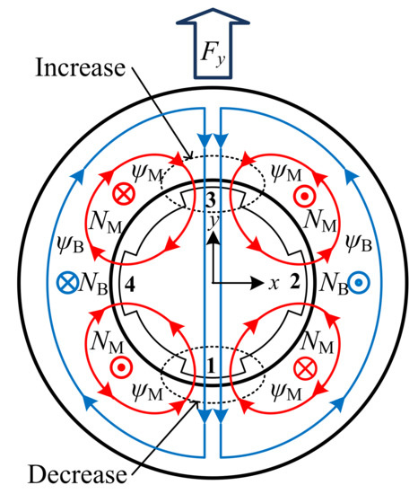
Figure 7.
The principle of the radial suspension force generation of BSynRM.
When the torque windings (current angular frequency ω1, pole-pair number pM) and suspension force windings (current angular frequency ω2, pole-pair number pB) meet the relationships of pB = pM ± 1 and ω1 = ω2, the suspension force on the rotor will be generated. The suspension force mathematical model of the PMa-BSynRM is established using the Maxwell tensor method. The suspension force components in the d-q reference frame are expressed as
where kc = 9μ0lrN12kd2I02/8πδ02, kM = πPMPBLB/8lrμ0N1N2, kL = mPMPB/4rPBN1, kd = sin[(q∙a)/2]/[qsin(a/2)], N1 and N2 are, respectively, the turns of torque windings and suspension force windings (each slot); μ0 is permeability of vacuum; δ0 is air gap length; l is motor core length; r is radius of rotor; a is slot angle of suspension fo rce windings; q is number of stator slots occupied by single phase single pole in suspension force windings; m is phase number of PMa-BSynRM; I0 is amplitude of equivalent excitation current produced by permanent magnet; IBd and IBq are current of suspension force windings in d- and q-axis, respectively.
3. Electromagnetic Characteristic Analysis
The models of the PMa-BSynRM I, PMa-BSynRM II and the BSynRM were constructed in the FEA software, and their electromagnetic properties were researched and compared.
The electromagnetic characteristics of the two PMa-BSynRMs and the BsynRM, with the same excitation, the same partition setting, the same simulation step and the same simulation time, were analyzed using FEA software. The magnetic flux density diagrams of the two PMa-BSynRMs and the BSynRM are shown in Figure 8.
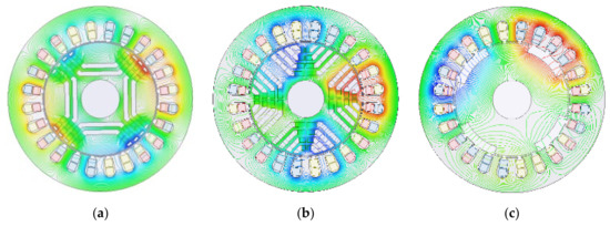
Figure 8.
Magnetic flux density in three motors. (a) PMa-BSynRM I; (b) PMa-BSynRM II; (c) BSynRM.
The no-load back-EMF is induced by the no-load air gap fundamental component of flux density, which is produced by the permanent magnet in the motor. It is a very important parameter of the PMa-BSynRM. Back EMF without load means that the electromagnetic capacity and harmonic of the permanent magnet will lead to torque fluctuation. The no-load air gap magnetic density and no-load back-EMF the of the two PMa-BSynRMs are shown in Figure 9 and Figure 10, respectively.
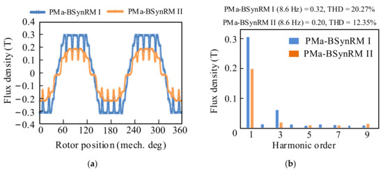
Figure 9.
Air gap flux density and harmonic analysis under no load. (a) Air gap flux density. (b) Harmonic analysis of Air gap flux density.
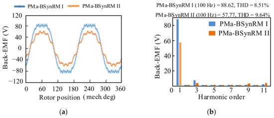
Figure 10.
Back-EMF and harmonic analysis under no load. (a) Back-EMF; (b) harmonic analysis of back-EMF.
Figure 9a shows that the peak value of the no-load air gap magnetic density of the PMa-BSynRM I is higher than that of the PMa-BSynRM II. The harmonic analysis of the air gap magnetic density is shown in Figure 9b, although the THD of the PMa-SynRM I is worse than that of the PMa-BSynRM II; the fundamental amplitude of the former is larger than that of the latter.
In Figure 10a, the no-load back-EMF of PMa-BSynRM I has a higher peak value than PMa-BSynRM II. According to the Fourier transform results of the no-load back-EMF, the amplitude of each harmonic can be obtained. Figure 10b shows the total harmonic distortion (THD) of the PMa-BSynRM I and the PMa-BSynRM II are 8.51% and 9.64%, respectively. Consistent with the harmonic analysis results of the air gap flux density, the THD of the PMa-BSynRM I is smaller than that of the PMa-BSynRM II, and the fundamental amplitude of the PMa-BSynRM I is larger than that of the PMa-BSynRM II.
In Figure 11, it is seen that when the load angle is 45°, the maximum torque of the three motors can be obtained. The maximum torque of PMa-BSynRM I was 3.62 N·m, which was greater than the maximum torques of PMa-BSynRM II and BSynRM. Owing to the fact that the suspension force is engendered by the superposition of the magnetic field of the permanent magnet and the suspension flux, the suspension flux passes through the thick permanent magnet and the non-magnetic material; the average suspension forces of the PMa-BSynRM I and PMa-BSynRM II, which were 180 N and 194 N, were smaller than that of the BSynRM, which was 250.07 N.
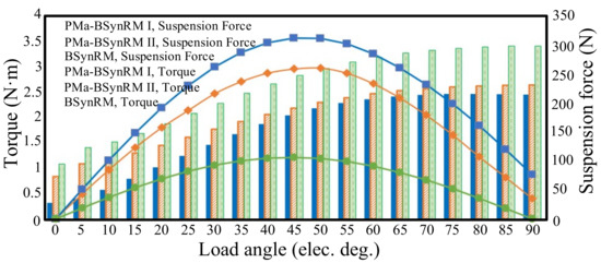
Figure 11.
Average suspension force and torque generated by three motors at different load angles.
The torque and suspension force of three motors at a 45° load angle are listed in Table 2. Figure 12 illustates the waveforms of torque and suspension force of the two PMa-BSynRMs and the BSynRM at a 45° load angle. By analyzing the waveform in Figure 12a, it can be found that the torque ripple of the PMa-BSynRM I was 16.52%, which was lower than the PMa-BSynRM II of 21.97% and the BSynRM of 52.11%. Consequently, the PMa-BSynRM I not only has relatively large torque, but also has advantages in torque ripple.
Table 2.
Torque and Suspension Force of Three Motors at a 45° Load Angle.
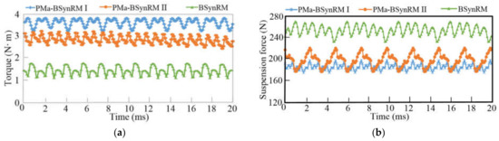
Figure 12.
Torque and suspension force generated by three motors at a 45° load angle. (a) Torque; (b) suspension force.
In Figure 12b, it is found that although the suspension force of the PMa-BSynRM I is slightly smaller than that of the PMa-BSynRM II and the smallest of three, the suspension force ripple of the PMa-BSynRM I was 11.68% lower than that of BSynRM and PMa-BSynRM II, 15.14% and 23.88%, respectively. Owing to the fact that the suspension force is engendered by the superposition of torque flux and suspension force flux, compared with BSynRM, the suspension force flux of PMa-BSynRM passed through thick permanent magnets and non-magnetic materials, so the suspension force of unit suspension force winding MMF was smaller. In order to compare the suspension force of PMa-BSynRM I and PMa-BSynRM II in more detail, the average suspension forces versus the current of suspension force windings are shown in Figure 13. It can be seen that as the current of suspension force windings changes, the average suspension force of PMa-BSynRM I is always larger than that of PMa-BSynRM II.
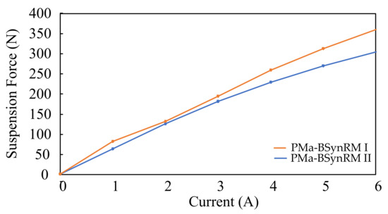
Figure 13.
Comparison of power factors between three motors.
From the analysis in Section 2, the power factor can be improved by placing permanent magnets in the rotor of the normal BSynRM. As shown in Figure 14, under the optimal current angle, the power factor of PMa-BSynRM was 0.89. In the current angle range of 0–90°, the power factor of the PMa-BSynRM I was always the largest.
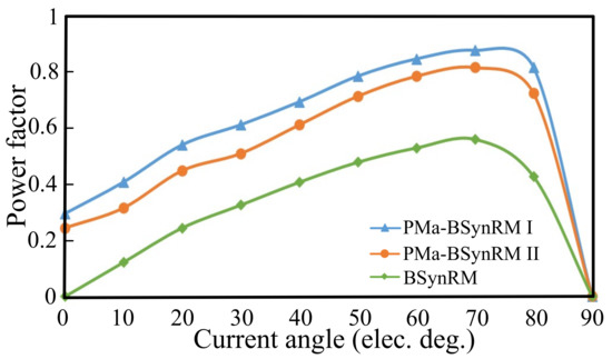
Figure 14.
Comparison of power factors between three motors.
The air gap flux density curves under the load of the three motors are depicted in Figure 15. Because the torque windings and the suspension force windings were electrified at the same time, the resultant produced by the air gap flux density under no load and the stator magnetic field mean that the air gap flux density under load was very different from the air gap flux density under no load. However, the air gap flux density of PMa-BSynRM I was still larger than that of the PMa-BSynRM II and BSynRM.
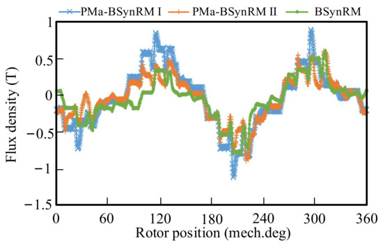
Figure 15.
Air gap flux density under load of three motors.
4. Vibration Analysis
The vibration and noise of the motor are mainly caused by the radial electromagnetic force, which is produced by the interaction of the stator and rotor magnetic fields. By using the Maxwell tensor method to process the air gap flux density of the motor under load that was obtained in the previous section, the radial electromagnetic force of the motor under load was obtained, and then the Fourier analysis was performed on it. The results are shown in Figure 16 and Figure 17.
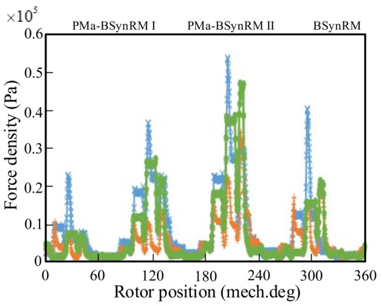
Figure 16.
Radial force waveform under load of three motors.
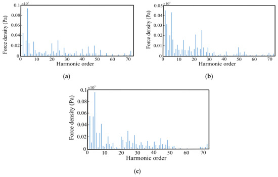
Figure 17.
Harmonic analysis of radial force under load of three motors. (a) PMa-BSynRM I. (b) PMa-BSynRM II. (c) BSynRM.
When the natural modal frequency of the motor is close to the frequency of the radial electromagnetic force in the air gap, resonance occurs, resulting in greater vibration and noise. The modal analysis of the motor was carried out with the ANSYS software. The mode shapes of the structure corresponding to each resonance frequency are listed in Table 3.
Table 3.
Modal Parameters from Simulation.
Because the frequency of the second-order mode was 2744.5 Hz, any harmonic frequency of the radial electromagnetic force smaller 2744.5 Hz could be ignored. In Figure 17, only the frequency of the 28th order of the radial force harmonics of two PMa-BSynRMs and the BSynRM under load was close to 2744.5 Hz. The amplitude of the 28th order of the radial force harmonics of the BSynRM was the biggest, and that of the PMa-BSynRM II was smallest. Consequently, compared with the PMa-BSynRM I and PMa-BSynRM II, the BSynRM under load was most likely to cause resonance.
The total nodal force acting on the stator teeth of the three motors was mapped onto the vibration models, respectively, as shown in Figure 18. Finally, the vibration acceleration and displacement of the three motors at 3000 r/min calculated by the FEA software are, respectively, illustrated in Figure 19 and Figure 20.
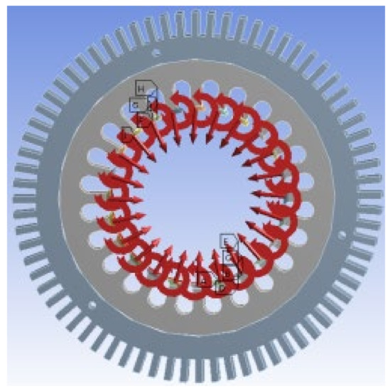
Figure 18.
Nodal force mapped onto vibration model.
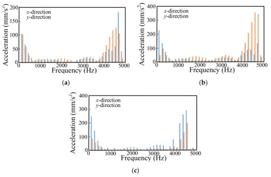
Figure 19.
Vibration acceleration of three motors under load at 3000 r/min. (a) PMa-BSynRM I; (b) PMa-BSynRM II; (c) BSynRM.
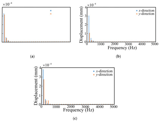
Figure 20.
Vibration displacement of three motors under load at 3000 r/min. (a) PMa-BSynRM I; (b) PMa-BSynRM II; (c) BSynRM.
The vibration acceleration of the two types of PMa-BSynRM were relatively large in the low- and high-frequency bands, and smaller in the middle-frequency band. Moreover, the vibration acceleration and vibration displacement of PMa-BSynRM I were significantly smaller than the other two motors. Therefore, PMa-BSynRM I has a more significant effect on suppressing vibration and noise.
5. Experimental Results
In order to authenticate the feasibility of the design and the correctness of the FEA result, as in Figure 21, the control system of the motor was designed. The manufactured rotors of two motors are illustrated in Figure 22. The digital control system of the PMa-BSynRM prototypes was built, as shown in Figure 23.
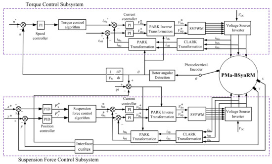
Figure 21.
Control system diagram for PMa-BSynRM.
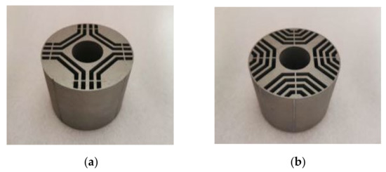
Figure 22.
Rotors of two prototypes. (a) Rotor of PMa-BSynRM I; (b) rotor of PMa-BSynRM II.
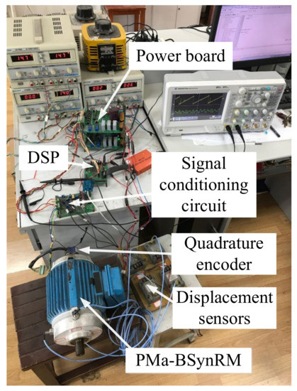
Figure 23.
Digital control system of prototypes.
A comparative experiment was designed using the rotor field-oriented control method. In the experiment, the BPMSM was running under no load, the given speed changes from 0 to 3000 r/min, and speed was detected by the photoelectric encoder. The speed waveform and angular position waveform are shown in Figure 24, it can be seen that both motors could reach the rated speed in about 0.2 s. The test results show that the torque subsystem of both two motors can be run stably at the rated speed.
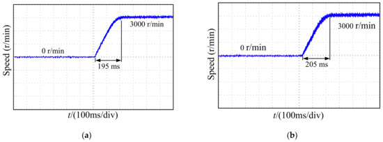
Figure 24.
Waveforms of speed. (a) PMa-BSynRM I. (b) PMa-BSynRM II.
The rotor radial displacement curves when the two motors were running at 3000 r/min and stably suspended are shown in Figure 25. It can be seen that the rotor can be suspended near the balanced position. Because the suspension force ripple of the PMa-BSynRM I is smaller than that of the PMa-BSynRM II, the radial displacement fluctuations decreased by 39.4% and 37.5% for PMa-BSynRM I and PMa-BSynRM II, respectively.
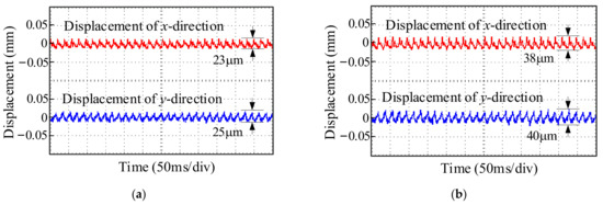
Figure 25.
Radical displacement of x- and y-direction. (a) PMa-BSynRM I. (b) PMa-BSynRM II.
As shown in Figure 26, the rotor trajectory coordinates of the two PMa-BSynRMs were all near the origin after the rotors are stable suspended. It is demonstrated that the suspension force can make the rotors achieve stable suspension. As the suspension force ripple of the PMa-BSynRM I was smaller than that of the PMa-BSynRM II, the range of rotor trajectory of the PMa-BSynRM I was relatively small.
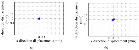
Figure 26.
Waveforms of rotor center of two PMa-BSynRMs with the speed of 3000 r/min. (a) PMa-BSynRM I. (b) PMa-BSynRM II.
The torque measurement result is shown in Figure 27. PMa-BSynRM I had a torque ripple of 18.1% under a load of 3.6 N·m, and the error from the FEA result was 9.6%. PMa-BSynRM II had a torque ripple of 25% under a load of 2.8 N·m, and the error from the FEA result was 14%.
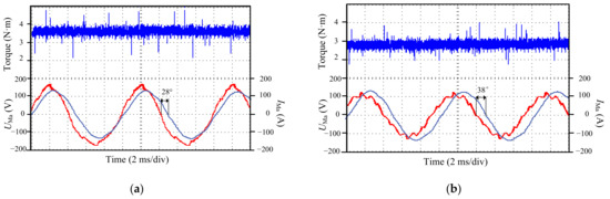
Figure 27.
Experimental results of torque and power factor. (a) PMa-BSynRM I. (b) PMa-BSynRM II.
The power factor is achieved by measuring the phase difference between the motor voltage and current. The results are shown in Figure 27. After calculation, the power factors of PMa-BSynRM I and PMa-BSynRM II were 88.3% and 78.8%, respectively, which are in line with the simulation results.
6. Conclusions
In this paper, two 24-stator-slot/4-rotor-pole PMa-BSynRMs with a NdFeB permanent magnet are designed. The motor structure, winding configuration, and operation principle were introduced, and characteristics of two PMa-BSynRMs and a traditional BSynRM are evaluated and compared using FEA. According to the FEA results, the following conclusions can be drawn.
In terms of the electromagnetic performances, the PMa-BSynRM I had advantages in back-EMF, air gap flux density, average torque and power factor. As for the suspension performance, the salient pole BSynRM produced the largest suspension force, and the PMa-BSynRM I had the smallest suspension force ripple. Through the vibration analysis is of the three motors, it can be found that the vibration of PMa-BSynRM I under load was lowest when the speed of the motor was 3000 r/min.
Author Contributions
Conceptualization, Y.H. and H.Z.; Data curation, Y.H. and Z.J.; Formal analysis, Y.H. and Z.J.; Funding acquisition, H.Z.; Investigation, M.G.; Methodology, Y.H.; Project administration, H.Z.; Resources, M.G.; Supervision, H.Z.; Validation, Y.H. and Z.J.; Visualization, Y.H. and M.G.; Writing—original draft, Y.H.; Writing—review & editing, Y.H. and M.G. All authors have read and agreed to the published version of the manuscript.
Funding
This research was funded in part by the National Natural Science Foundation of China, grant number 61973144, and in part by the Priority Academic Program Development of Jiangsu Higher Education Institutions, grant number PAPD-2018-87.
Institutional Review Board Statement
Not applicable.
Informed Consent Statement
Not applicable.
Data Availability Statement
Data sharing not applicable.
Conflicts of Interest
The authors declare no conflict of interest.
References
- Zhang, W.; Cheng, L.; Zhu, H. Suspension force error source analysis and multidimensional dynamic model for a centripetal force type-magnetic bearing. IEEE Trans. Ind. Electron. 2020, 67, 7617–7628. [Google Scholar] [CrossRef]
- Zhang, W.; Yang, H.; Cheng, L.; Zhu, H. Modeling based on exact segmentation of magnetic field for a centripetal force type-magnetic bearing. IEEE Trans. Ind. Electron. 2020, 67, 7691–7701. [Google Scholar] [CrossRef]
- Chen, J.; Zhu, J.; Severson, E.L. Review of bearingless motor technology for significant power applications. IEEE Trans. Ind. Appl. 2020, 56, 1377–1388. [Google Scholar] [CrossRef]
- Sun, X.D.; Chen, L.; Yang, Z.B. Overview of bearingless permanent-magnet synchronous motors. IEEE Trans. Ind. Electron. 2013, 60, 5528–5538. [Google Scholar] [CrossRef]
- Mukherjee, V.; Rasilo, P.; Martin, F.; Belahcen, A. Effect of magnetic forces and magnetostriction on the stator vibrations of a bearingless synchronous reluctance motor. IEEE Trans. Magn. 2019, 55, 1–4. [Google Scholar] [CrossRef]
- Zhang, H.; Zhu, H.; Zhang, Z.; Xie, Z. Design and simulation of control system for bearingless synchronous reluctance motor. In Proceedings of the 2005 International Conference on Electrical Machines and Systems, Nanjing, China, 27–29 September 2005; pp. 554–558. [Google Scholar] [CrossRef]
- Chiba, A.; Rahman, M.A.; Fukao, T. Radial force in a bearingless reluctance motor. IEEE Trans. Magn. 1991, 27, 786–790. [Google Scholar] [CrossRef]
- Chiba, A.; Hanazawa, M.; Fukao, T.; Rahman, M.A. Effects of magnetic saturation on radial force of bearingless synchronous reluctance motors. IEEE Trans. Ind. Appl. 1996, 32, 354–362. [Google Scholar] [CrossRef]
- Morales-Castorena, A.; Soong, W.L.; Ertugrul, N. Analysis and design of the stator windings of a bearingless motor for comparisons of radial force capabilities with different rotors. In Proceedings of the 2005 International Conference on Power Electronics and Drives Systems, Kuala Lumpur, Malaysia, 28 November–1 December 2005; pp. 1161–1166. [Google Scholar] [CrossRef]
- Takemoto, M.; Yoshida, K.; Tanaka, Y.; Chiba, A.; Fukao, T. Synchronous reluctance type bearingless motors with multi-flux barriers. In Proceedings of the 2007 Power Conversion Conference—Nagoya, Nagoya, Japan, 2–5 April 2007; pp. 1559–1564. [Google Scholar] [CrossRef]
- Mukherjee, V.; Pippuri, J.; Saarakkala, S.E.; Belahcen, A.; Hinkkanen, M.; Tammi, K. Finite element analysis for bearingless operation of a multi-flux barrier synchronous reluctance motor. In Proceedings of the 2015 18th International Conference on Electrical Machines and Systems, Pattaya, Thailand, 25–28 October 2015; pp. 688–691. [Google Scholar] [CrossRef]
- Diao, X.; Zhu, H.; Qin, Y.; Hua, Y. Torque ripple minimization for bearingless synchronous reluctance motor. IEEE Trans. Appl. Supercond. 2018, 28, 1–5. [Google Scholar] [CrossRef]
- Ding, H.; Zhu, H.; Hua, Y. Optimization design of bearingless synchronous reluctance motor. IEEE Trans. Appl. Supercond. 2018, 28, 1–5. [Google Scholar] [CrossRef]
- Vagati, A.; Pastorelli, M.; Francheschini, G.; Petrache, S.C. Design of low-torque-ripple synchronous reluctance motors. IEEE Trans. Ind. Appl. 1998, 34, 758–765. [Google Scholar] [CrossRef]
- Boazzo, B.; Vagati, A.; Pellegrino, G.; Armando, E.; Guglielmi, P. Multipolar ferrite-Assisted synchronous reluctance machines: A general design approach. IEEE Trans. Ind. Electron. 2015, 62, 832–845. [Google Scholar] [CrossRef]
- Trancho, E.; Ibarra, E.; Arias, A.; Kortabarria, I.; Jurgens, J.; Marengo, L.; Fricassè, A.; Gragger, J.V. PM-assisted synchronous reluctance machine flux weakening control for EV and HEV applications. IEEE Trans. Ind. Electron. 2018, 65, 2986–2995. [Google Scholar] [CrossRef]
- Bianchi, N.; Degano, M.; Fornasiero, E. Sensitivity analysis of torque ripple reduction of synchronous reluctance and interior PM motors. IEEE Trans. Ind. Appl. 2015, 51, 187–195. [Google Scholar] [CrossRef]
- Liu, H.; Joo, K.; Oh, Y.; Lee, H.; Seol, H.; Jin, C.; Kim, W.; Lee, J. Optimal design of an ultra-premium-efficiency PMA-synchronous reluctance motor with the winding method and stator parameters to reduce flux leakage and minimize torque pulsations. IEEE Trans. Magn. 2018, 54, 1–5. [Google Scholar] [CrossRef]
- Islam, M.Z.; Arafat, A.; Choi, S. Design of five-phase bearingless permanent magnet assisted synchronous reluctance motor for high speed applications. In Proceedings of the 2018 IEEE Energy Conversion Congress and Exposition, Portland, OR, USA, 23–27 September 2018; pp. 4419–4424. [Google Scholar] [CrossRef]
- Ji, Z.; Zhu, H.; Xu, Y.; Wu, M. Optimization design of permanent magnet assisted single winding bearingless synchronous reluctance motor. IEEE Trans. Appl. Supercond. 2020, 30, 1–5. [Google Scholar] [CrossRef]


Publisher’s Note: MDPI stays neutral with regard to jurisdictional claims in published maps and institutional affiliations. |
© 2021 by the authors. Licensee MDPI, Basel, Switzerland. This article is an open access article distributed under the terms and conditions of the Creative Commons Attribution (CC BY) license (http://creativecommons.org/licenses/by/4.0/).