Article

Experimental Study on Behavior of Coolants, Particularly the Oil-Cooling Method, in Electric Vehicle Motors Using Hairpin Winding

1
School of Mechanical Engineering, Chung-Ang University, Seoul 06974, Korea
2
School of Computer Science and Engineering, Chung-Ang University, Seoul 06974, Korea
*
Author to whom correspondence should be addressed.
Energies 2021, 14(4), 956; https://doi.org/10.3390/en14040956
Submission received: 28 November 2020 / Revised: 8 February 2021 / Accepted: 9 February 2021 / Published: 11 February 2021

Abstract

:
This paper analyzes the characteristics of oil behavior in the oil-cooling of motors with hairpin winding to understand how to maximize cooling performance. The oil cooling is performed by directly spraying oil onto the motor components. The results show that as the temperature of the oil increases, the viscosity decreases, and the oil film is formed more evenly; however, oil splashing also increases. Similarly, as the flow rate increases, oil splashing also increases, but the amount of oil forming the oil film increases. However, the oil film is not affected by the rotor’s rotation. In contrast, the immersed oil is found to be closely related to the rotor’s rotation. As the rotational speed increases, the immersion oil is mixed with the air, and oil churning occurs. The mixing phenomenon increases as the temperature and flow rate of the oil increases. The higher the oil level, the greater the oil churning. As the oil is mixed with air, the heat transfer coefficient decreases, which adversely affects the thermal management of the motor. As a result, when considering the oil film and the immersion oil, the optimal oil temperature, flow rate, and oil level are at 60 °C, 0.140 kg/s, and 85 mm, respectively. The results of this paper give important information about EV motor cooling and can contribute to the development of high-performance motors.

1. Introduction

Recently, interest in ecofriendly vehicles has been increasing due to the increased awareness of environmental issues. Ecofriendly vehicles include hybrid vehicles (HEVs), plug-in hybrid vehicles (PHEVs), electric vehicles (EVs), and hydrogen vehicles (FCEVs) [1,2]. These ecofriendly vehicles use motors as power generation devices. Among them, electric and hydrogen cars generate power using only a motor. The motor is powered by electricity and directly affects the performance and life of the vehicle. In particular, the heat generated by the motor affects the performance and life of an EV. The heat from the motor is generated by joule losses in the coil, iron losses in the stator and rotor cores, and other stray load and mechanical losses [3,4,5]. Recently, as the performance of motors has increased, so has the power density. Consequently, the joule losses generated in the coil has increased, resulting in severe heat generation in the coil [6,7]. As the performance of motors continues to improve, this heat problem will become increasingly more serious, rendering effective motor cooling very important.
There are air-cooling, water-cooling, and oil-cooling methods to cool motors [8,9]. The air- and water-cooling methods are mainly used for industrial motors and motors under 100 kW because the cooling performance of these methods is not very high [10,11,12,13]. EV motors require miniaturization and high performance, so the motor requires a power density of at least 100 kW [14]. Therefore, the oil-cooling method with high cooling performance is necessary for cooling EV motors. Oil cooling is a method of cooling a motor by directly spraying oil onto a heat source inside the motor [15,16]. Huang et al. [17] compared indirect and direct oil-cooling methods. Indirect cooling is a method of cooling by creating grooves in the housing, similar to the conventional water jacket in the water-cooling method. Direct cooling is a method of directly cooling the stator by creating grooves between the stator and the housing. At a similar cooling power, the direct cooling method lowers the average temperature of the stator twice and improves the heat transfer performance. Huang et al. also compared the cooling performance of various cross-sections of grooves, including rectangular, oval, and elliptical cross-sections, in the direct cooling method [18]. As a result, motors with oval channels were best cooled to a maximum temperature of 130.45 °C. For high performance EV motors, a high-power density is necessary, and this increases the heat generation in the coil. However, cooling the stator through conduction is not suitable for removing heat from the coil. This is because the heat transfer rate in the radial direction of the motor is low due to the insulating paper between the stator and the coil.
Cooling by direct contact between the coil and oil is the most effective. Ponomarev et al. [19] cooled a motor by completely immersing the inside of the motor with oil. The coil, stator, and rotor were cooled by direct contact with the oil. The hot spot of the coil was cooled to 124 °C, and the heat transfer performance was improved. Although direct contact with oil improved the cooling performance, the performance of the motor degraded due to friction loss in the rotor. Therefore, the method of immersing the inside of the motor in oil is not suitable for the motor driver. Davin et al. [20] cooled a motor by directly injecting oil on the end-winding of the coil and compared different oil-cooling injections. The cooling performance was compared using the full cone nozzle, flat jet nozzle, dripping, and multijets. The dripping injector was most effective because oil was injected at the top of the motor and had a higher flow rate at the end-winding surface. When the dripping injector was used, the average temperature of the end-winding was approximately 109 °C. However, the target motor of previous studies using the oil-cooling method was a general winding motor. These motors do not satisfy the miniaturization and high performance required for EV motors. In recent EVs, hairpin winding motors have been widely implemented [21]. However, few previous studies have applied oil cooling to a hairpin winding motor. The hairpin winding motor has an improved power density by reducing the unnecessary space between coils [22]. Although the power density and performance are improved, a hairpin winding motor generates a lot of heat; thus, more in depth research is needed to apply the oil-cooling method.
In this study, the characteristics of oil behavior in a hairpin winding motor are analyzed to understand how to maximize the cooling performance. We analyzed the distribution of oil in a Chevrolet Bolt EV motor that is a hairpin winding motor suitable for miniaturization and has high efficiency. Because the upper part of the coil is cooled by the sprayed oil, the oil flow and the formation of an oil film on the outer surface of the coil are investigated in this paper. The lower part of the motor is cooled by being immersed in oil, and the ratio of mixing with the air by rotating the rotor is investigated. Furthermore, a parametric study with various oil conditions is conducted. First, the oil flow according to the temperature and flow rate of the injected oil is analyzed through an experiment. Then, the influence of the immersion oil based on the rotation of the rotor in each oil injection condition is analyzed. Subsequently, the oil film formation and air mixing ratio based on the oil level is analyzed. The results show that the oil film formed most evenly when the oil temperature and flow rate were 60 °C and 0.140 kg/s, respectively. The air mixing ratio increased as the oil temperature and flow rate increased. In addition, the air mixing ratio was affected by rotation. The results of this paper provide important information on the oil flow characteristics and the effects of rotor rotation of the oil-cooled motor with hairpin winding. This work can contribute to the development of a cooling system for high-performance EV motors.

2. Materials and Methods

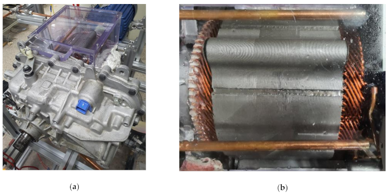
2.1. Target Motor Description

Figure 1 shows the target motor used in the experiment. The target motor is a General Motors Chevrolet’s ‘Bolt EV’ motor currently used in their EVs. This motor is a permanent magnet synchronous motor (PMSM) that uses a hairpin winding. The motor has a peak torque of 360 Nm and a peak power of 150 kW. Figure 1a is a picture of the motor assembly. The overall length of the motor assembly is 530 mm, and the height is 316 mm. The motor assembly is an integrated motor and reducer. The part with acrylic housing for flow visualization is the motor. The upper part of the motor housing is made of acrylic to enable the observation of the flow of oil in the motor’s stator and coil. The part next to the motor is the reducer. The width of the motor is 235 mm, and the width of the reducer is 430 mm. Figure 1b is a picture of the stator and coil, which are the main parts of the motor. The length of the stator is 180 mm, and the outer diameter is 204 mm. There are six coil conductors between each tooth of the stator. The end-winding on the left side of the motor is called the welded part, and the end-winding on the right side is called the crown part. Unlike the crown part, the welded part has white insulating paper between the coils.

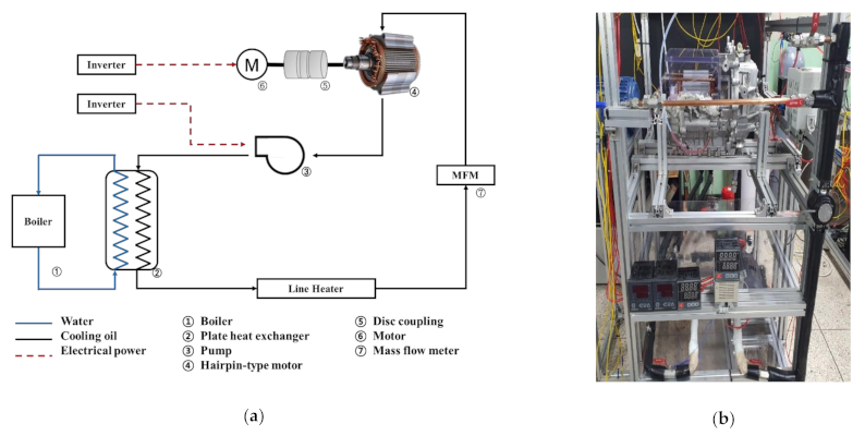
2.2. Experimental Setup

Figure 2 shows the experimental equipment used to analyze the effects of the rotation of the rotor on the flow of the injected oil and immersion oil to cool the motor. Figure 2a,b are a schematic and photograph of the experimental equipment, respectively. The rotor of the motor is rotated using an industrial motor (TEFC 2HP, Hyosung ENG, Republic of Korea). The rotor of the target motor and the shaft of the industrial motor are connected using a disk coupling (SRA-80C Disk Coupling, Sungwoo Transmission, Republic of Korea). The rotational speed of the motor is controlled by an inverter (SV015iG5A-2, LS ELECTRIC CO., Republic of Korea) and is measured using an rpm meter (EE-2N, KONEX, Japan). The cooling oil is circulated using an oil pump (TOP-210 HBE, DH PUMP Engineering Co., Republic of Korea). The flow rate of the supplied oil is measured by a flow meter (KTR-550-MF-T-Ex, KOREA FLOW METER IND. CO., Republic of Korea), and the oil pump is controlled by an inverter (SV022iG5A-2, LS ELECTRIC CO., Republic of Korea) to control the flow rate. The temperature of the oil is controlled by supplying heat from a boiler (Kiturami Electric Boiler, Kiturami, Republic of Korea) through a heat exchanger. The fine temperature is controlled by heating tape. The oil that moves to the top of the motor is sprayed through the pipe to the stator and the end-winding of the coil.

2.3. Analysis Method

We studied the oil behavior inside the motor to understand how to improve a motor’s thermal management. The thermal management of a motor is closely related to the amount of heat transfer. Therefore, we focus on the flow characteristics and coolant properties that affect the heat transfer amount. The amount of heat transfer is proportional to the area the oil touches. The upper part of the end-winding is cooled by the injected oil. The sprayed oil splashes after it touches the coil or flows according to the coil’s shape. Because the coil’s shape is very complex, the oil’s flow field is complicated. Therefore, it is important to analyze the flow characteristics of the oil and understand the oil film on the outer surface of the coil. In contrast, the lower part of the end-winding is cooled by being submerged in oil. The immersion oil has no flow compared to the sprayed oil. However, the immersion oil mixes with the air under the influence of the rotor’s rotation. When oil mixes with air, the properties of the mixture change. In particular, the thermal conductivity related to the amount of heat transfer is lowered. Therefore, it is important to understand the mixing ratio of oil and air.
First, we conducted an experiment to understand the oil flow and oil film on the upper part of the coil. The welded part has insulating paper between the coils, so the oil film is formed evenly. In contrast, the crown part is more difficult to analyze because oil flows through the space between the coils. Therefore, we analyzed the oil film formation at the crown’s upper part. To define the area covered by oil on the outer surface of the coil, we introduce the definition of the oil film formation rate. The oil film formation rate is used to quantify and compare the oil film formation on the coil. The oil film formation rate is the ratio of the area where the oil film is formed to the surface area of the upper coil. The oil film formation rate follows the following equation:
Roilfilm = Aoil/Acoil
where Roilfilm is the oil film formation rate, Acoil is the area of the upper coil, and Aoil is the area of contact between the coil and oil.
Next, we conducted an experiment to understand the thermal conductivity of the oil in which the lower part of the coil is immersed. To define the thermal conductivity of the oil inside the motor, we used the air mixing ratio. We analyzed the air mixing ratio through an experiment. In addition, to understand the effects of the air mixing ratio, the thermal conductivity of the mixture was calculated with Equation (2) [23].
kmixture = (x + y)/(x/koil + y/kair)
where kmixture is the thermal conductivity of the mixture, x is the oil ratio, y is the air ratio, koil is the thermal conductivity of oil, and kair is the thermal conductivity of air.
In the next section, the oil behavior, which has a large influence on a motor’s thermal management, is analyzed through flow visualization experiments. In particular, by intensively analyzing the oil flow field and the thermal conductivity of the mixture, we can analyze the oil behavior inside the motor that affects heat transfer. Since the upper part of the coil is cooled by the sprayed oil, we analyze the oil film formation rate. The oil flow on the outer surface of the coil is also analyzed. Next, for the lower part of the coil, because it is cooled by being immersed in oil, we analyze the air mixing ratio of the oil. The thermal conductivity of the mixture is calculated and compared based on the air mixing ratio.

3. Results and Discussion

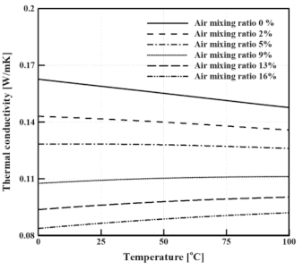
3.1. Thermal Conductivity of Oil and Air Mixture

We used the ATF SP-IV, an automatic transmission oil, as the cooling oil for the motor. Figure 3 shows the properties of the cooling oil according to temperature, which is important for analyzing the oil’s flow because the properties of oil change significantly with temperature. Figure 3a,b are graphs showing the density and viscosity of the oil according to temperature, respectively. The density of the oil decreases proportionally with increasing temperatures and the viscosity of the oil changes rapidly with temperature. More specifically, the viscosity rapidly decreases as the temperature increases up to 50 °C, after which it gradually decreases.
Figure 4 shows the calculations of the thermal conductivity of the oil and air mixture based on the air mixing ratio using Equation (2). The thermal conductivity of the oil decreases with an increase in temperature. In contrast, the thermal conductivity of air increases as the temperature increases. For this reason, as the air mixing ratio increases, the thermal conductivity of the mixture also increases as the temperature increases. Since the upper part of the coil is cooled by the injected oil, mixing with air does not occur. Therefore, the thermal conductivity of the injected oil is the thermal conductivity when the air mixing ratio is 0%. In contrast, the lower part of the coil is cooled by being submerged in oil, which is mixed with air by the rotation of the rotor. Therefore, the air mixing ratio varies based on the oil condition and the rotational speed of the rotor. As a result, the upper part of the coil can only be analyzed for the oil flow and the oil film formation, and the lower part of the coil can only be analyzed for the air mixing ratio.

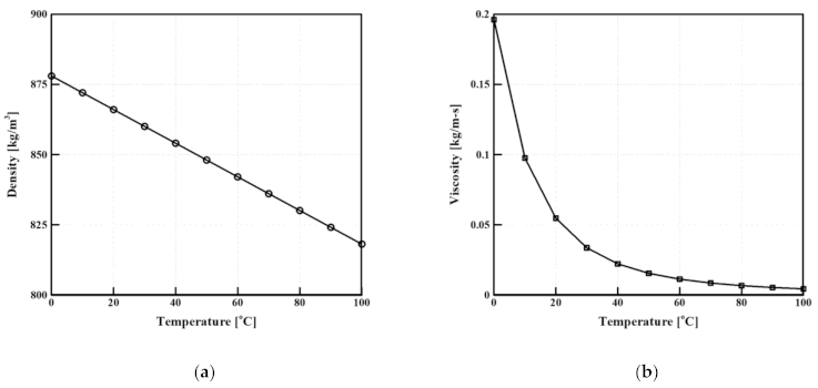
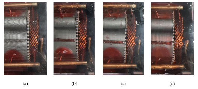
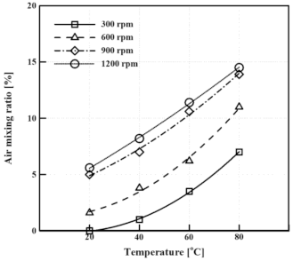
3.2. The Effects of Oil Temperature on the Oil Behavior

The flow field of the upper part of the coil was analyzed using the oil film formation rate. The properties of oil are greatly affected by temperature. In particular, the viscosity of oil drops rapidly as the temperature increases, as shown in the graph in Figure 3b. Flow visualization experiments conducted under various rotational speeds to analyze the effects of the rotation of the rotor were undertaken to understand the effects of oil temperature on the flow field. The temperature of oil inlet is maintained at atmospheric temperature before driving and varied from 60 to 80 °C during driving. Therefore, we decided that the range of the oil inlet temperature is from 20 to 80 °C. Figure 5 is a graph showing the oil film formation rate, which quantifies the experimental results. The oil flow rate was fixed at 0.084 kg/s. The experimental results were photographed and observed from various angles after waiting for the oil flow to become a steady state. After that, the oil film was imaged and the oil film formation rate was calculated using Equation (1), and there were errors. The error rate was approximately 4%. When the oil temperature was 20 °C, and the rotational speed was 1200 rpm, the oil film formation rate was the lowest at 63%. When the temperature of the oil was 60 °C and the rotational speed was 300 rpm, the oil film formation rate was the highest at 80%. The oil film formation rate was 76% when the oil temperature was either 40 °C or 80 °C. As the oil temperature increased up to 60 °C, the oil film formation rate increased and then decreased thereafter. The trend in the curves for the oil film formation rate based on the temperature for each rotational speed condition was similar, and as the rotational speed of the rotor increased, the oil film formation rate decreased. However, the reduction was not large.
Figure 6 shows pictures of the upper part of the coil at different oil temperatures at a flow rate of 0.084 kg/s and a rotational speed of 600 rpm. Figure 6a shows the experimental results when the oil temperature was 20 °C, which resulted in little oil splashing. However, the viscosity of the oil was very high at 0.0547 kg/m∙s, which caused the formation of a thick oil film on the outer surface of the coil; however, there was not a wide formation of this film. Figure 6b shows the results at the oil temperature of 40 °C. Compared with 20 °C, the viscosity of the oil was lowered to 0.0222 kg/m∙s, thereby inducing the formation of a wider oil film on the outer surface of the coil. However, the viscosity of the oil was still high, so there was little oil splashing, and the oil film was thick. Figure 6c shows the results at the oil temperature of 60 °C. The viscosity of the oil at 60 °C was 0.0113 kg/m s, which is approximately five times lower than that at 20 °C. The oil splashing increased, and the oil film was thinner but more evenly spread compared with that at 40 °C. Figure 6d shows the results at the oil temperature of 80 °C. The viscosity of the oil decreased to 0.0067 kg/m∙s, and the amount of oil splashed increased. The amount of oil lost increased, and the oil film was less evenly spread than that at 60 °C. Therefore, the oil temperature at which the oil film was most evenly formed was at 60 °C.
The change in the properties of the mixture was analyzed because there was no change in the flow field at the lower part of the coil. The effects of the oil temperature and the rotation of the rotor on the oil in which the bottom half of the motor was immersed were analyzed. When oil was mixed with air, the thermal conductivity decreased, which has a negative effect on motor cooling. Figure 7 shows the mixing ratio of oil and air based on oil temperature and rotational speed. When the temperature of the oil at 300 rpm was 20 °C, the air mixing ratio was the lowest at 0%, and the thermal conductivity was 0.160 W/m∙K. When the oil temperature was 80 °C and the air mixing ratio was 7%, the thermal conductivity was 0.119 W/m∙K, which is 26% lower than that for oil at 20 °C. When the oil temperature at 1200 rpm was 20 °C, the air mixing ratio was 5.6%, and the thermal conductivity was 0.117 W/m∙K. When the oil temperature was 80 °C, the air mixing ratio was the highest at 14.5%, and the thermal conductivity was 0.091 W/m∙K. When the temperature of the oil increased, the air mixing ratio increased, and the thermal conductivity of the mixture decreased. This is because as the oil temperature increases, the viscosity of the oil decreases, making the thermal conductivity more affected by the rotation of the rotor. When the rotational speed of the rotor increased, the air mixing ratio also increased. In particular, when increasing from 600 rpm to 900 rpm, the air mixing ratio increased by approximately 3.5%, demonstrating the largest increase. At speeds above 900 rpm, the air mixing ratio did not increase significantly.

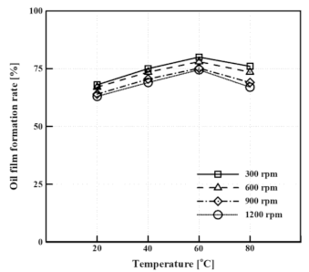
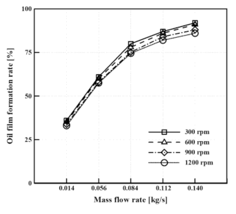
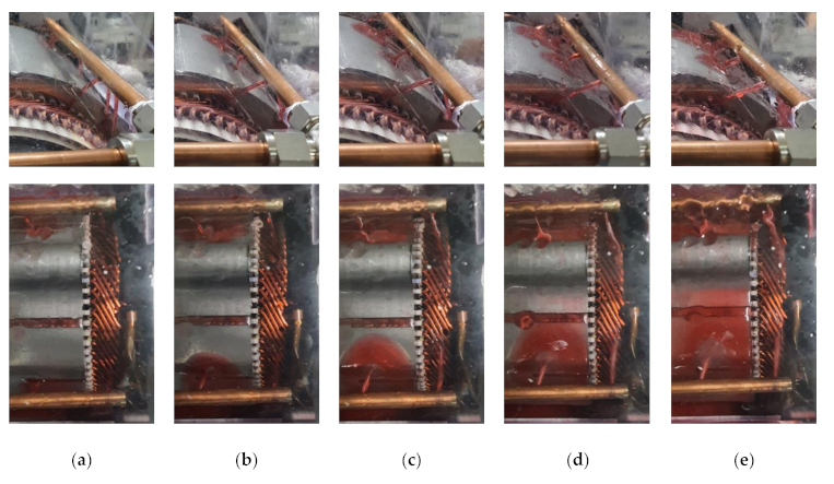
3.3. The Effects of Oil Flow Rate on Oil Behavior

The flow field of oil at the upper part of the coil is important for the understanding of oil cooling, so the oil film formation rate was analyzed. Experiments were conducted to understand the effects of the flow rate of the injected oil on the flow field. The oil temperature was fixed at 60 °C. The oil flow rate is used in the electric vehicle motor from 6 to 0.140 kg/s. Therefore, the oil flow rate is widely set from 2 to 0.140 kg/s to consider severe operating condition. Figure 8 shows the oil film formation rate according to the flow rate of the oil. The error rate was approximately 3%. The oil film formation rate according to the flow rate of the oil at 300 rpm was analyzed. The oil film formation rate at 0.028 kg/s was the lowest at 36%. The oil film formation rate at 0.056 kg/s was 61%, which is 25% higher than that at 0.028 kg/s. The oil film formation rate at 0.084 kg/s was 80%, which is 19% higher than that at 0.056 kg/s. The oil film formation rate at 0.112 kg/s was 87%, which is 7% higher than that at 0.084 kg/s. Finally, the oil film formation rate at 0.140 kg/s was 92% with the oil film evenly formed. The results show that as the flow rate of oil increases, the oil film formation rate also increases. However, the increase in the oil film formation rate decreases as the flow rate increases. When increasing from 2–0.056 kg/s, the increase in the oil film formation rate is the largest, and when increasing from 8–0.140 kg/s, the increase in the oil film formation rate is smallest. For each rotational speed condition, the trend in the oil film formation rate according to the flow rate is similar. When the rotational speed increases, the oil film formation rate decreases. However, since the difference is not large, the oil film formation rate can be said to not be significantly affected by rotation.
Figure 9 shows pictures of the upper part of the coil at a temperature of 60 °C and a rotational speed of 600 rpm. Figure 9a presents the experimental results at the flow rate of 0.028 kg/s. The oil inlet velocity was very slow at 0.295 m/s. Therefore, the oil was sprayed from the pipe in a parabolic shape on the outer surface of the coil. As a result, it was not sprayed on the top of the coil, and thus, it was difficult to form an oil film. Figure 9b shows the results at the flow rate of 0.056 kg/s. The oil inlet velocity was 0.589 m/s, which is twice as fast as that at 0.028 kg/s. However, the oil was still sprayed on the outer surface of the coil in a parabolic shape. Figure 9c shows the experimental results when the flow rate was 0.084 kg/s. The oil inlet velocity was 0.884 m/s, and the oil was sprayed onto the coil in a straight line. The oil film was formed more evenly than that at 0.056 kg/s. Figure 9d shows the experimental results when the flow rate was 0.112 kg/s. The oil inlet velocity was 1.179 m/s, which is four times faster than that at 0.028 kg/s. Some oil splashing occurred, but the formation of the oil film was wider. Finally, Figure 9d shows the results when the flow rate was 0.140 kg/s. The oil inlet velocity was the fastest at 1.474 m/s. As the flow rate increased, oil splashing increased, but the amount of oil forming the oil film also increased. Therefore, as the flow rate increased, the formation of the oil film was wider and more evenly spread.
It is important to understand the changes in the properties of the mixture rather than the flow of oil at the lower part of the coil. Figure 10 shows the mixing ratio of oil and air based on the oil flow rate and rotational speed. When the oil flow rate was 0.028 kg/s at 300 rpm, the air mixing ratio was the lowest at 0%, and the thermal conductivity of the mixture was 0.160 W/m∙K. When the oil flow rate was 0.140 kg/s, the air mixing ratio was 11%, and the thermal conductivity was 0.105 W/m∙K, which is 34% lower than that at 0.028 kg/s. When the flow rate of the oil was 0.028 kg/s at 1200 rpm, the air mixing ratio was 0.8%, and the thermal conductivity was 0.142 W/m∙K. When the oil flow rate was 0.140 kg/s, the air mixing ratio was the highest at 16%, and the thermal conductivity was 0.090 W/m∙K. As the oil flow rate increased, the air mixing ratio increased, and the thermal conductivity of the mixture decreased. In particular, when the flow rate was greater than 0.112 kg/s, the air mixing ratio increased significantly. This is because when the flow rate of oil increases, the flow of the oil is fast, and the amount of oil splashing increases. As the rotational speed of the rotor increases, the air mixing ratio also increases. However, at 0.028 kg/s, the difference between the air mixing ratios for different rotational speeds was not large, and as the flow rate increased, the air mixing ratio was more affected by rotational speed. At speeds above 900 rpm, the air mixing ratio did not increase significantly.

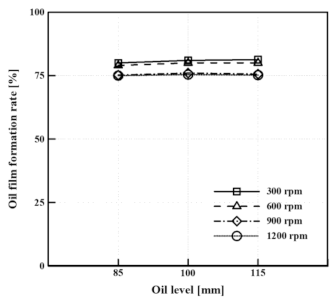
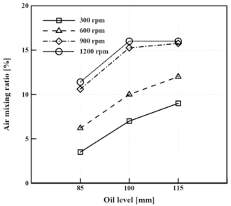
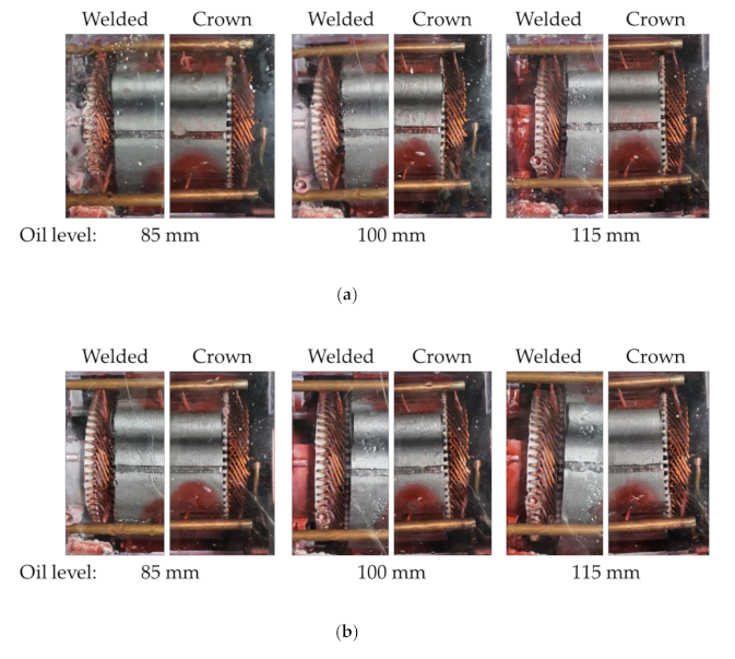
3.4. The Effects of Oil Level on the Oil Behavior

The oil film formation rate was analyzed because the flow field of the oil at the upper part of the coil was more significant than the properties of the oil. Experiments were conducted to understand the effects of the oil, in which the lower part of the motor was immersed, on the flow field. The oil temperature and flow rate were fixed at 60 °C and 0.084 kg/s. The oil level was changed from 85 mm to 115 mm to describe the changed amount of immersed oil. Figure 11 shows the oil film formation rate based on the oil level. The error rate was approximately 4%. Three oil levels were compared. An oil level of 85 mm from the bottom of the motor is the level that the rotor touches. In addition, oil levels of 100 mm and 115 mm were compared. When the rotational speed was 300 rpm, the oil film formation rate according to the oil level was analyzed. When the oil levels were 85, 100, and 115 mm, the oil film formation rates were similar at 80, 81, and 81.3%, respectively. The oil level had no effect on the formation of the oil film. As the rotational speed increased, the oil film formation rate decreased, but the differences were not large. Therefore, the oil level and rotational speed did not affect the oil film formation rate.
It is significant to understand the change in the properties of the mixture rather than the flow of oil at the lower part of the coil. Figure 12 shows the mixing ratio of oil and air according to oil level and rotational speed. When the oil level was 85 mm and the rotational speed was 300 rpm, the air mixing ratio was the lowest at 3.5%, and the thermal conductivity was 0.134 W/m∙K. When the oil level was 100 mm, the air mixing ratio was 7%, which is 3.5% higher than when the oil level was 85 mm. When the oil level was 115 mm, the air mixing ratio was 9%, and the thermal conductivity was 0.111 W/m∙K, 17% lower than that when the oil level was at 85 mm. The air mixing ratio at 600 rpm was 3% higher than that at 300 rpm but showed a similar trend. When the oil level was 85 mm at 900 rpm, the air mixing ratio was the lowest at 10.6%. When the oil level was 100 mm at 900 rpm, the air mixing ratio was 15.3%, which is 4.7% higher than that when the oil level was 85 mm. When the oil level was 115 mm, the air mixing ratio was 16%. The air mixing ratio at 900 rpm and 1200 rpm demonstrated similar trends.
Since there is no oil flow in the lower part of the coil, it is important to understand the changes in the mixture’s properties. However, as the oil level increases, the flow field cannot be ignored. Figure 13 shows the pictures of the welded and crown parts of the coil at 60 °C and 0.084 kg/s. Figure 13a shows the results for each oil level at 900 rpm. In the crown part, the oil film formation by oil level was similar. This is because the oil level does not affect the formation of the oil film at the top of the coil, and the temperature and flow rate of the oil have a significant influence on the formation of the oil film. In the welded part, when the oil level was 115 mm, the oil was churned by the rotor and went over the shaft. As the oil churned, it mixed more with the air, which lowered the thermal conductivity. Figure 13b shows the results for each oil level at 1200 rpm. Even if the rotational speed increased, the oil film formation was similar for each oil level. This indicates that not only the oil level but also the rotational speed do not affect the formation of the oil film at the top of the coil. At 1200 rpm, the churning of the oil at the oil level of 100 mm can be observed. When the oil level was 100 mm, churning occurred at 1200 rpm, and when the oil level was 115 mm, churning occurred at 900 rpm. Therefore, the oil level has a significant influence on the air mixing ratio and causes churning due to the rotor’s rotation.

4. Conclusions

In this study, the characteristics of oil behavior in a motor using hairpin winding were analyzed to better understand how to maximize motor cooling performance. A Chevrolet Bolt EV motor, a hairpin winding motor suitable for miniaturization and having high efficiency, was selected as the target motor. Since the thermal management of the motor is closely related to the heat transfer ability, the flow characteristics and properties of the oil were analyzed.
The properties of oil change greatly depending on the mixing ratio of oil and air. Therefore, the thermal conductivity, a property related to motor cooling, was analyzed. As the air mixing ratio increases, the thermal conductivity of the mixture decreases. However, since the oil at the upper part of the motor does not mix with air, it has a thermal conductivity of oil when the air mixing ratio is 0%. In contrast, the lower part of the motor is cooled by being submerged in oil, which is mixed with the air by the rotation of the rotor. Therefore, the air mixing ratio varies depending on the oil condition and the rotor’s rotational speed. As a result, only the upper part of the coil is suitable for the analysis of the oil flow and the formation of oil film, and the lower part of the coil is suitable for the analysis of the air mixing ratio.
First, an experiment was conducted to understand the effects of the oil temperature. The viscosity of the oil changes rapidly with increases in temperature. As the temperature of the oil increases, the viscosity decreases, and the oil film is formed more evenly; however, this also increases the oil splash. When the rotational speed of the rotor increases, the oil film formation rate decreases, but the reduction is not large. In the case of immersing in oil, as the temperature of the oil increases, the viscosity of the oil decreases and is more affected by the movement of the rotor. Therefore, the air mixing ratio increases and the thermal conductivity of the mixture decreases. The thermal conductivity of the mixture decreases by up to 48.5% depending on the air mixing ratio.
Next, an experiment was conducted to understand the effects of the oil flow rate. When the oil flow rate was 0.028 kg/s, the oil was sprayed from the pipe in a parabolic shape onto the outer surface of the coil. When the oil flow rate was over 0.084 kg/s, oil was sprayed onto the coil in a straight line. As the flow rate increased, the oil splashing increased, but the amount of oil forming the oil film also increased. Additionally, an increase in the flow rate was accompanied by an increase in the air mixing ratio, which was also significantly affected by the rotational speed of the rotor.
Subsequently, an experiment was conducted to understand the effects of oil level, the results of which were compared for oil levels of 85, 100, and 115 mm. The oil level had no effect on the oil film formation rate. In contrast, the air mixing ratio was greatly influenced by the oil level. Oil churning occurred at 1200 rpm when the oil level was over 100 mm and at 900 rpm when the oil level was over 115 mm. When the oil level increased, oil churning occurred, and the air mixing ratio increased. Therefore, it is important to select an appropriate oil condition and level because the cooling performance decreases when the air mixing ratio increases.
The results of this study indicate that when considering the oil film and the immersion oil, the optimal oil temperature, flow rate, and level are 60 °C, 0.140 kg/s, and 85 mm, respectively. In order to apply the oil cooling method, it is important to understand the contact area between the oil and the motor and the thermal conductivity of the mixture. Based on these results, the temperature distribution of the motor can be predicted. A high-performance motor can be developed if the results of this paper are applied to the development of cooling systems for EV motors.

Author Contributions

Conceptualization, T.H.; methodology, T.H., N.G.H. and M.S.K.; validation, T.H. and N.G.H.; formal analysis, T.H.; investigation, N.G.H., K.H.R.; writing—original draft preparation, T.H.; writing—review and editing, N.G.H., K.H.R. and D.K.K. All authors have read and agreed to the published version of the manuscript.

Funding

This research received no external funding.

Institutional Review Board Statement

Not applicable.

Informed Consent Statement

Not applicable.

Acknowledgments

This research was supported by the Chung-Ang University Young Scientist Scholarship in 2020. This work was also supported by the Korea Institute of Energy Technology Evaluation and Planning (KETEP) and the Ministry of Trade, Industry and Energy (MOTIE) of the Republic of Korea (No. 20206810100030), (No.20008021).

Conflicts of Interest

The authors declare no conflict of interest.

References

  1. Yildirim, M.; Polat, M.; Kurum, H. A survey on comparison of electric motor types and drives used for electric vehicles. In Proceedings of the 2014 16th International Power Electronics and Motion Control Conference and Exposition, Antalya, Turkey, 21–24 September 2014; pp. 218–223. [Google Scholar]
  2. De Santiago, J.; Bernhoff, H.; Ekergård, B.; Eriksson, S.; Ferhatovic, S.; Waters, R.; Leijon, M. Electrical motor drivelines in commercial all-electric vehicles: A review. IEEE Trans. Veh. Technol. 2012, 61, 475–484. [Google Scholar] [CrossRef] [Green Version]
  3. Zhang, M.; Yang, Y.; Mi, C.C. Analytical approach for the power management of blended-mode plug-in hybrid electric vehicles. IEEE Trans. Veh. Technol. 2012, 61, 1554–1566. [Google Scholar] [CrossRef]
  4. Fujimoto, H.; Harada, S. Model-based range extension control system for electric vehicles with front and rear driving-braking force distributions. IEEE Trans. Ind. Electron. 2015, 62, 3245–3254. [Google Scholar] [CrossRef]
  5. Miyama, Y.; Hazeyama, M.; Hanioka, S.; Watanabe, N.; Daikoku, A.; Inoue, M. PWM carrier harmonic iron loss reduction technique of permanent-magnet motors for electric vehicles. IEEE Trans. Ind. Appl. 2016, 52, 2865–2871. [Google Scholar] [CrossRef]
  6. Ulu, C.; Korman, O.; Kömürgöz, G. Electromagnetic and thermal design/analysis of an induction motor for electric vehicles. Int. J. Mech. Eng. Robot. Res. 2019, 8, 239–245. [Google Scholar] [CrossRef]
  7. Zhang, C.; Guo, Q.; Li, L.; Wang, M.; Wang, T. System efficiency improvement for electric vehicles adopting a Permanent Magnet Synchronous Motor direct drive system. Energies 2017, 10, 2030. [Google Scholar] [CrossRef] [Green Version]
  8. Lim, D.H.; Lee, M.Y.; Lee, H.S.; Kim, S.C. Performance evaluation of an in-wheel motor cooling system in an electric vehicle/hybrid electric vehicle. Energies 2014, 7, 961–971. [Google Scholar] [CrossRef] [Green Version]
  9. Carriero, A.; Locatelli, M.; Ramakrishnan, K.; Mastinu, G.; Gobbi, M. A Review of the State of the Art of Electric Traction Motors Cooling Techniques; SAE Technical Papers; SAE International: Warrendale, PA, USA, 2018; Volume 2018. [Google Scholar]
  10. Kim, M.S.; Lee, K.S.; Um, S. Numerical investigation and optimization of the thermal performance of a brushless DC motor. Int. J. Heat Mass Transf. 2009, 52, 1589–1599. [Google Scholar] [CrossRef]
  11. Kim, C.; Lee, K.S.; Yook, S.J. Effect of air-gap fans on cooling of windings in a large-capacity, high-speed induction motor. Appl. Therm. Eng. 2016, 100, 658–667. [Google Scholar] [CrossRef]
  12. Rehman, Z.; Seong, K. Three-D numerical thermal analysis of electric motor with cooling jacket. Energies 2018, 11, 92. [Google Scholar] [CrossRef] [Green Version]
  13. Ye, Z.N.; Luo, W.D.; Zhang, W.M.; Feng, Z.X. Simulative analysis of traction motor cooling system based on CFD. In Proceedings of the 2011 International Conference on Electric Information and Control Engineering, Wuhan, China, 15–17 April 2011; pp. 746–749. [Google Scholar]
  14. Kim, C.; Lee, K.S. Numerical investigation of the air-gap flow heating phenomena in large-capacity induction motors. Int. J. Heat Mass Transf. 2017, 110, 746–752. [Google Scholar] [CrossRef]
  15. Park, M.H.; Kim, S.C. Thermal characteristics and effects of oil spray cooling on in-wheel motors in electric vehicles. Appl. Therm. Eng. 2019, 152, 582–593. [Google Scholar] [CrossRef]
  16. Ye, L.; Tao, F.; Wei, S.; Qi, L.; Xuhui, W. Experimental research on the oil cooling of the end winding of the motor. In Proceedings of the 2016 IEEE Energy Conversion Congress and Exposition (ECCE), Milwaukee, WI, USA, 18–22 September 2016; pp. 6–9. [Google Scholar]
  17. Huang, Z.; Nategh, S.; Lassila, V.; Alaküla, M.; Yuan, J. Direct oil cooling of traction motors in hybrid drives. In Proceedings of the 2012 IEEE International Electric Vehicle Conference, Greenville, SC, USA, 4–8 March 2012; pp. 1–8. [Google Scholar]
  18. Huang, Z.; Marquez, F.; Alakula, M.; Yuan, J. Characterization and application of forced cooling channels for traction motors in HEVs. In Proceedings of the 2012 20th International Conference on Electrical Machines, Marseille, France, 2–5 September 2012; pp. 1212–1218. [Google Scholar]
  19. Ponomarev, P.; Polikarpova, M.; Pyrhönen, J. Thermal modeling of directly-oil-cooled permanent magnet synchronous machine. In Proceedings of the 2012 20th International Conference on Electrical Machines, Marseille, France, 2–5 September 2012; pp. 1882–1887. [Google Scholar]
  20. Davin, T.; Pellé, J.; Harmand, S.; Yu, R. Experimental study of oil cooling systems for electric motors. Appl. Therm. Eng. 2015, 75, 1–13. [Google Scholar] [CrossRef]
  21. Momen, F.; Rahman, K.; Son, Y.; Savagian, P. Electrical propulsion system design of Chevrolet Bolt battery electric vehicle. In Proceedings of the 2016 IEEE Energy Conversion Congress and Exposition (ECCE), Milwaukee, WI, USA, 18–22 September 2016. [Google Scholar]
  22. Jung, D.S.; Kim, Y.H.; Lee, U.H.; Lee, H.D. Optimum design of the electric vehicle traction motor using the hairpin winding. In Proceedings of the IEEE Vehicular Technology Conference, Yokohama, Japan, 6–9 May 2012. [Google Scholar]
  23. Çengel, Y.A.; Ghajar, A.J.; Afshin, J.; Kanoglu, M. Heat and Mass Transfer: Fundamentals and Applications; McGraw-Hill Education: New York, NY, USA, 2014; ISBN 0071077863. [Google Scholar]
Figure 1. Target motor: (a) motor assembly; and (b) stator and coil.
Energies 14 00956 g001
Figure 2. Experimental equipment: (a) schematic; and (b) photograph.
Energies 14 00956 g002
Figure 3. Cooling oil properties: (a) density; (b) viscosity.
Energies 14 00956 g003
Figure 4. The thermal conductivity [W/m∙K] of the oil and air mixture.
Energies 14 00956 g004
Figure 5. Oil film formation rate based on temperature at 0.084 kg/s.
Energies 14 00956 g005
Figure 6. Oil flow according to temperature at 0.084 kg/s, 600 rpm: (a) 20; (b) 40; (c) 60; (d) 80 °C.
Energies 14 00956 g006
Figure 7. Air mixing ratio according to temperature at 0.084 kg/s.
Energies 14 00956 g007
Figure 8. Oil film formation rate according to the mass flow rate at 60 °C.
Energies 14 00956 g008
Figure 9. Oil flow according to the mass flow rate at 60 °C, 600 rpm: (a) 0.028; (b) 0.056; (c) 0.084; (d) 0.112 kg; and (e) 0.140 kg/s.
Energies 14 00956 g009
Figure 10. Air mixing ratio according to the mass flow rate at 60 °C.
Energies 14 00956 g010
Figure 11. Oil film formation rate according to oil level at 60 °C, 0.084 kg/s.
Energies 14 00956 g011
Figure 12. Air mixing ratio based on oil level at 60 °C, 0.084 kg/s.
Energies 14 00956 g012
Figure 13. Oil flow according to oil level at 60 °C, 0.084 kg/s: (a) 900 rpm; and (b) 1200 rpm.
Energies 14 00956 g013
Publisher’s Note: MDPI stays neutral with regard to jurisdictional claims in published maps and institutional affiliations.

