1. Introduction
Thermal power engineering is the leading branch of the global energy sector and plays a major role in the development of industry in many countries of the world, but it exceeds all other industries in terms of emissions of pollutants into the atmosphere (ash particles, sulfur dioxide, nitrogen and carbon oxides). In the furnaces of power boilers, various fuels are burned and in particular solid ones: lignite, coal, coke. Kazakhstan possesses huge reserves of hydrocarbons (33.600 million tons of coal—3.8% of world reserves, 30,000 million barrels of oil—1.8% of world reserves and 1.5 trillion cubic meters of natural gas—0.8% of world reserves), which have a significant impact on the formation and state of the world energy market [
1].
The main fuel for Kazakh thermal power plants, which generate up to 85% of electricity, is low-grade coal with high ash content. Its use as the main energy source leads to problems in flame stabilization, slagging of convective heating surfaces, air pollution with fly ash, carbon and nitrogen oxides, hydrocarbons, and other combustion products. In most regions of the Republic of Kazakhstan, the ecological situation is not only unfavorable, but also catastrophic. According to the latest data provided by the energy agency, Kazakhstan carries out 43.7% of emissions of pollutants into the atmospheric air of Central Asia, while CO
2 emissions reached 12.8 tons per capita [
2,
3,
4].
Since the coal fuel and energy cycle is one of the most environmentally hazardous, developed countries refuse to use it, choosing a more environmentally friendly type of fuel—natural gas. For developing countries, the impact on the environment remains a secondary factor, and traditional coal-fired energy is successfully developing due to its low cost. The development of the energy sector is leading in the direction of creating technologies to reduce the negative impact on the environment [
5].
In Kazakhstan, coal will remain the main type of fuel for the thermal power industry, despite the global trend of a decrease in the share of coal-fired thermal power plants [
6]. In this regard, in the face of tightening environmental requirements for the environment, the urgent task of the domestic thermal power industry is the introduction of energy-efficient, environmentally friendly “clean” coal technologies at Kazakhstani coal-fired TPPs, which make it possible to control the main processes of the formation of harmful dust and gas emissions and develop recommendations for their reduction [
7,
8,
9,
10,
11,
12,
13,
14].
Currently, various methods are used to minimize harmful dust and gas emissions at coal-fired TPPs, the main of which are: changing combustion technology and cleaning gases after combustion. Changes in combustion technology include the use of modified burners, recirculation of exhaust gases, staged fuel combustion, plasma preparation of low-grade coals for combustion, radiation technologies and combustion of fuel in fluidized bed furnaces. For Kazakhstan, the most acceptable technology for implementation is staged fuel combustion, since its implementation at operating TPPs requires low investment and contributes to a significant reduction in NOx emissions. In addition, when this technology is used in combination with other measures to control and reduce the formation of NOx, it is possible to achieve the maximum reduction in their emissions.
As is known, two-stage fuel combustion technology (or as it is also called, OFA technology) is one of the most effective methods to reduce the concentration of harmful emissions and, first of all, the most dangerous of them—nitrogen oxides [
15,
16,
17,
18,
19,
20]. The implementation of two-stage fuel combustion is carried out by installing secondary and even tertiary air holes above the main combustion zone. In this case, a reduction and afterburning zone is formed in the furnace (see
Figure 1). With the correct organization of staged combustion, it is possible to reduce the content of nitrogen oxides by 30–40%. This decrease is explained by the formation of combustion zones in the furnace, characterized by excess air and temperature levels.
As the conducted literature review has shown, research in this area is relevant to this day, since not only Kazakh scientists, but also scientists around the world are engaged in them. So, in [
18], a study was carried out of two-stage combustion of high-ash Ekibastuz coal on a modernized PK-39-2M boiler of the 325 MW power unit of the Aksu power plant (Kazakhstan). The researchers obtained positive results of operation, as well as data from boiler tests, which confirm that the proposed technical solutions for the organization of staged combustion, incorporated in its design, ensured the achievement of optimal performance during the operation of the boiler in the entire operating range of loads (60–100%).
Studies by foreign scientists in [
19] were aimed to optimize the air distribution for the proposed SOFA installation in a 500 MWe tangential-firing boiler that has 20 identical units in Korea. These authors found that the actual air distribution can be adjusted depending on the coal properties such as the ash slagging propensity, because too large SOFA ratios caused negative impacts on the boiler performance and increased the propensity of slagging and corrosion.
According to the results obtained in [
20], the effect of changing the configuration and the location of OFA nozzles on flue gas temperature, CO, O
2 and NO
x content in the flue gas, the heat flux along the height of the furnace chamber and the burnout in the slag hopper and fly ash were analyzed.
In this article, the main purpose of the study was to identify the main optimal parameters of use (height of installation of additional injectors, their diameter and number, air volume through injectors, etc.) on a low-power boiler of Kazakhstan (BKZ-75 Shakhtinskaya TPP, Kazakhstan), since no one has previously conducted such studies for such boilers. For the successful use of OFA technology, it was necessary to determine the optimal amount of air supplied to additional injectors, in view of the fact that this parameter has a very strong effect, as shown by the results of this study, on the main characteristics of the combustion process of pulverized coal fuel, in particular on the temperature distribution and nitrogen oxides in the furnace space.
Modernization and re-equipment of existing power boilers of Kazakhstani coal-fired TPPs, testing of commissioning works by industrial tests when introducing the above-described technology of two-stage combustion of high-ash fuel have significant limitations due to the high labor intensity and high cost. In this regard, the main methods for studying the processes occurring in the furnaces of a TPP are methods of numerical modeling and carrying out on their basis computational experiments that adequately reflect real physical processes occurring in the furnaces.
2. Materials and Methods
To carry out numerical experiments on the introduction of the technology of two-stage fuel combustion, the furnace of the BKZ-75 boiler at Shakhtinskaya TPP (Shakhtinsk, Kazakhstan) was selected, the diagram of which is shown in
Figure 2. The steam boiler BKZ 75 is vertical-water-tube, made according to a U-shaped arrangement [
21]. The boiler is equipped with four pulverized coal burners, installed two burners from the front and rear in one tier.
Figure 3 shows a diagram of a pulverized coal burner in longitudinal section. The boiler burns the dust of the Karaganda coal grade KR-200. The main technical characteristics of the boiler plant, as well as the composition of the fuel used are given in the
Table 1,
Table 2 and
Table 3.
In full accordance with the characteristics of the boiler and fuel, we have created a physical model of the furnace. When creating it, the necessary technical data and geometrical parameters were used (dimensions of the chamber and used burners, productivity, excess air ratio, number of burners and additional nozzles and their height, method, volume and rate of air mixture and air supply, composition of fuel and oxidizer and many others), which correspond to the real technological processes of combustion of high-ash Karaganda coal in the furnace of the BKZ-75 boiler at Shakhtinskaya TPP.
Figure 4 shows the geometry of the furnace and arrangement of the burners.
The mathematical model that describes the processes of convective heat and mass transfer in physicochemically active flows in the presence of combustion is based on the laws of conservation and transfer of mass, momentum, energy and chemicals. They represent a complex system of equations in which it is necessary to take into account the non-isothermal and multiphase nature of the medium, pressure gradient, turbulence, mass forces, radiant heat transfer, multistage chemical reactions, and many others. In flows with the processes of mixing various components, with combustion reactions, etc., it is necessary to add the equation for the conservation of the mixture components. For rotating flows of fuel and air, in the general case, a solution to a complex three-dimensional problem is required.
To implement computational experiments, the FLOREAN software package was used [
10,
22,
23,
24,
25,
26]. This computer software package was developed at the Institute for Energy and Systems Engineering, Technical University of Braunschweig, Germany and allows complex computational experiments to simulate reacting multiphase flows in real geometry (CHP and TPP combustion chambers).
To study the processes of heat and mass transfer in furnaces, it is necessary to use physical, mathematical and chemical models, including a system of three-dimensional Navier-Stokes equations and heat and mass transfer equations taking into account the source terms, which are determined by the chemical kinetics of the fuel combustion process, nonlinear effects of thermal radiation and interphase interaction [
22,
23,
24,
25]. The authors used the standard k-ε model as a turbulence model. The basic equations that describe the processes of heat and mass transfer in the furnace can be written in a generalized form as follows:
where
—generalized transport variable,
—generalized exchange rate,
—source term, which are given in the
Table 4. The system of Equation (1) is a composition of four components: convective, diffusion, dissipative and source. This system has no analytical solution and can only be solved numerically. We have chosen the control volume method, which is often and successfully used for the numerical solution of differential equations describing complex processes of heat and mass transfer in the furnace of power boilers [
22,
23,
24,
25,
26,
27].
When modeling the processes occurring in the combustion chamber of the investigated boiler, the combustion models were considered in the form of the following stages: pyrolysis with the release of volatile substances and the formation of coke residue, combustion of volatile products, combustion of carbon monoxide and coke residue. When choosing models of pyrolysis and combustion, the authors refused to use bulky systems with many components. In this work, the authors used a one-stage pyrolysis model described in [
28].
When describing the pyrolysis process, volatile substances are considered as fictitious hydrocarbons, and to determine the rate of combustion of pyrolysis products, the authors used the Eddy-Dissipation Model (EDM) concept proposed by Magnussen and considered in detail in [
29]. These models have proven themselves quite well and are an excellent compromise for reducing computational costs [
10,
22,
24,
26]. In addition, in this article, the heterogeneous reaction of solid carbon combustion on the surface of coke particles is determined by the diffusion of oxygen from the environment into the boundary layer and into the porous medium of a spherical particle, as well as by the reaction between carbon and oxygen on the surface of the particle.
In most cases, during pulverized coal combustion, researchers deal with lightly loaded flows, i.e., when the maximum volume concentration of the solid phase does not exceed 1%. The diameter of solid particles does not exceed 1000 microns, and the average particle diameter throughout the volume does not exceed 100 microns. Then the process of solid fuel combustion in combustion chambers can be represented as follows: the flame is a two-phase gas-dispersed system, and the effect of the solid phase on the aerodynamics of the flow is insignificant.
The effect of the solid phase on the coefficients of turbulent exchange is considered using the following empirical formula [
10,
22,
24,
26]:
where
μp is turbulent viscosity including solids,
σp,turb is turbulent Schmidt-Prandtl number including particles,
ρp is particles density,
ρ is gas phase density.
When considering the processes of heat transfer in combustion chambers, heat exchange by radiation makes the greatest contribution to the total heat transfer. In this regard, modeling the transfer of radiation in reacting flows is one of the most important stages in calculating the processes of heat and mass transfer in real combustion chambers. To calculate heat transfer by radiation in the combustion chamber of the investigated boiler, a six-flux model of radiant heat transfer was used and described in [
30]. This model took into account heat transfer between solid particles and gas by means of radiation when determining the integral coefficients of absorption and radiation. Due to the presence of a solid phase in the flow, it is impossible to write down the general transport equation in the radiation model; therefore, in the equation for enthalpy, the source term is determined separately for each phase.
For the gas phase:
where
Kabs,G—optical coefficient of absorption of the gas phase,
σ—Stefan–Boltzmann’s coefficient,
TG—temperature of gas phase.
Likewise, for the individual solids fraction
k:
where
Kabs,P,k—optical coefficient of absorption of the solid phase,
TP,k—temperature of solid phase for the individual solids fraction
k.
NO reactions were calculated by post-processing the CFD results. Thermal NO reactions were based on the extended Zeldovich mechanism. The main reaction for the formation of fuel NO
x is the reaction of oxidation of nitrogen in the fuel bound into complex organic compounds that are released during the release of volatiles. They quickly convert to hydrocyanic acid HCN or ammonia NH
3. Nitrogen in HCN or NH
3 compounds can leave them when NO is reduced to N
2 or when oxidized to NO. Decomposition also occurs during the afterburning of NO with hydrocarbons, with the formation of HCN again. There are many kinetic models for the formation of nitrogen oxides for numerical simulations. The most common among them is the model proposed by Mitchell and Tarbell [
10,
22,
24,
26,
31].
For the numerical solution of differential equations describing complex processes of heat and mass transfer in the combustion chamber of power boilers, the authors chose the control volume method, which is often and successfully used by researchers in this field [
22,
23,
24,
32,
33,
34], which is based on dividing the furnace of the investigated boiler into small volumes, over which the differential equations of the mathematical model are integrated. The number of control volumes depends on the geometry of the furnace, its dimensions, and the location of the burners. To carry out a numerical experiment on fuel combustion in the basic (traditional) regime (OFA = 0%), the furnace of the BKZ-75 boiler is divided into control volumes (
Figure 5). The finite difference mesh has a resolution: 59 × 32 × 67, which is 138,355 control volumes.
To implement two-stage combustion, it is necessary to place additional injectors in the upper part of the boiler and change the finite-difference grid.
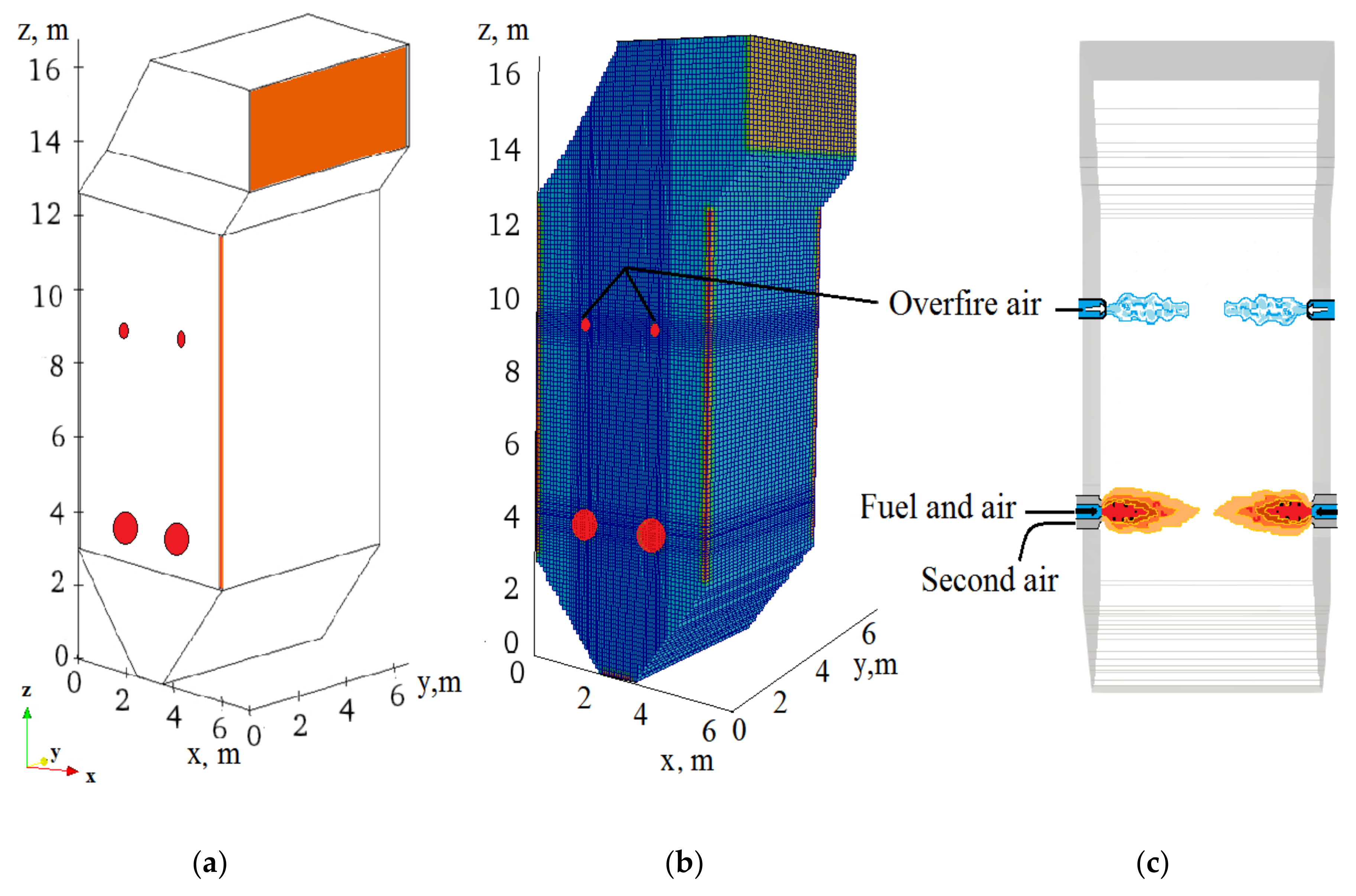
Figure 6 shows a general view of the furnace of the BKZ-75 boiler (
Figure 6a), its breakdown into control volumes for numerical simulation (
Figure 6b), arrangement of burners and injectors for the implementation of two-stage combustion technology (
Figure 6c). Now the finite difference mesh has a resolution: 90 × 32 × 158, which is 455,040 control volumes. This grid has been repeatedly refined to find a compromise between the convergence of the numerical solution and the time of the computational experiment. So, according to the results obtained previously for the combustion chamber of the PK-39 boiler, 300 MW Aksu TPP (Kazakhstan), the authors of this article came to the conclusion that an increase in the number of control volumes affects the results of numerical calculations, especially in the areas of fuel and oxidizer supply. Therefore, increasing the resolution of the grid in the second case due to the need to reduce the size of the cells in the injector arrangement, since there is a sharp change in characteristics due to receipt of an additional amount of oxidant. The main characteristics of the furnace of the BKZ-75 boiler when organizing two-stage combustion (OFA) of fuel are given in
Table 5.
Various additional air supply modes have been selected, when: 0% (basic version), 5%, 10%, 15%, 18%, 20%, 25% and 30% of the total air volume enters through the injectors in the upper part of the furnace.
Table 6 shows the flow rate and velocities of additional air supplied through the injectors for the above regimes.
3. Results
As a result of numerical experiments on the implementation of two-stage combustion of high-ash Karaganda coal, an aerodynamic flow pattern (distribution of the total velocity vector), temperature and concentration fields of carbon monoxide CO and nitrogen dioxide NO
2 were obtained throughout the volume and at the outlet of the furnace of the BKZ-75 boiler. A comparative analysis of the main characteristics of the heat and mass transfer process for the investigated regimes of supplying additional air through the injectors is carried out (see
Table 6). In view of the fact that the operating modes of the boiler with the percentage ratios of the additional air volume of 0%, 10% and 18% are key, as will be shown in Chapter 4, the authors of this article decided to present the results in the form of figures and graphs only for these values, omitting intermediate results. However, the complete picture of the research, showing all the investigated modes of boiler operation, is presented in Figure 14 and
Table 7.
3.1. Results of CFD-Calculations for the Study of the Aerodynamics of the in-Furnace Space
Figure 7 shows the distributions of the full velocity vector in the cross-sections of the furnace of the BKZ 75 boiler in the zone of the burner (h = 4.0 m,
Figure 7a), in the zone of the injectors (h = 9.4 m,
Figure 7b), and in the central section (y = 3.3 m,
Figure 7c) of the BKZ-75 boiler furnace for the base case (OFA = 0%) and using the two-stage combustion technology (OFA = 18%).
It is seen that for these two investigated regimes of air supply through the injectors, the torch core is located in the center of the furnace and is determined by the collision region of flows from the anti-burners. Comparing the investigated modes in
Figure 7a in the zone of the burner (h = 4.0 m), one can see how in both cases the flows collide, directed from the direct-flow burners, which are located opposite each other.
However, overall, the flow pattern changes with additional air supply through the injectors, the aerodynamic characteristics of the combustion of a pulverized coal flame when two-stage combustion is introduced differ from the base case. So, in
Figure 7b, the supply of additional air through the injectors is clearly visible in comparison with the case of the absence of such a supply (basic regime,
Figure 7a).
For the case OFA = 18%, the flows directed from the injectors, after the collision, are additionally cut into two vertical vortices above the zone of the burner installation (
Figure 7b), closer to the center of the furnace, which favorably affects the mixing of fuel and oxidizer and, accordingly, the completeness of combustion of pulverized coal.
When the exhaust gases move towards the outlet of the furnace, the velocity decreases. In contrast to the traditional combustion of pulverized coal (OFA = 0%), the vortex character of the flow at the outlet from the furnace when using the two-stage combustion technology weakens (OFA = 18%), which leads to a decrease in the velocity (
Figure 7c).
3.2. Results of CFD Calculations on the Study of Temperature Characteristics
Figure 8 illustrates the temperature distribution in the central (y = 3.3 m) section of the furnace of the BKZ-75 boiler for the base case (OFA = 0%) and using the two-stage fuel combustion technology (OFA = 10%, OFA = 18%). Analysis of the Figure shows that with an increase in the volume of air supplied through the injectors, the temperature in the center of the furnace increases, and in the zone of their location decreases. This leads to the fact that the average temperature values over the central section of the furnace of the BKZ-75 boiler differ insignificantly: for the base case OFA = 0% it is 1094.8 °C, with OFA = 10%–1154.8 °C and for OFA = 18%–1150.0 °C.
Figure 9 shows three-dimensional (
Figure 9a) and two-dimensional graphs (
Figure 9b) of the distribution of the cross-section average temperature T along the height h of the furnace for the studied regimes of additional air supply. Comparative analysis of
Figure 9a shows that with an increase in the volume of air supplied through the injectors, the temperature in the zone of the burner increases: at OFA = 10%, T = 750.35 °C, at OFA = 18%, T = 744.08 °C compared to the base case (conventional combustion): with OFA = 0%, T = 620.56 °C. The use of two-stage combustion technology causes a decrease in the oxygen concentration in the zone of the most intense combustion (in the zone of the burner), which leads to a decrease in the total excess air ratio and an increase in the flame temperature in this zone.
In the zone where the injectors are located, more air is supplied, chemical reactions are more intense, and the temperature rises in comparison with the temperature in the zone of the burner (
Figure 9a). However, the more additional cold air is supplied through the injectors, the lower the average temperature value in the zone of the injectors becomes OFA = 0%, T = 987.30 °C; OFA = 10%, T = 918.56 °C and OFA = 18%, T = 879.17 °C.
When moving towards the outlet from the furnace, the temperature field flattens out and the differences in temperature values for different cases of OFA regimes decrease. So, the average value of the temperature at the outlet from the furnace is for OFA = 0%, T = 885.79 °C; OFA = 10%, T = 865.90 °C and OFA = 18% T = 856.27 °C.
The temperature distribution over the height of the furnace is confirmed by experimental data (
Figure 9b) obtained directly at the operating Shakhtinskaya TPP [
35], and at the outlet from the furnace space, its theoretical value, calculated according to the CBTI method [
37] for the basic variant (OFA = 0%). Comparing the results obtained, it can be noted that with an increase in the volume of air supplied through the OFA-injectors, a shift in the location of the flame core and an increase in the length of the zone of maximum temperatures are observed (
Figure 9b, curves 2, 3).
With an increase in temperature, the rate of elementary reactions increases, the quality of mixing of the fuel air mixture and secondary air increases, and the level of emissions of harmful substances from incomplete combustion decreases. An increase in the temperature in the torch core and a decrease in it at the outlet has a significant effect on the chemical processes of the formation of combustion products, since temperature is the main factor in determining the rate of the combustion reaction of the components of the fuel mixture. However, this does not automatically reduce the level of combustion products such as carbon monoxide CO and nitrogen oxides NOx.
Their effective reduction can be ensured at the next stage of pulverized coal fuel combustion, when additional air is supplied to the furnace through OFA—injectors, i.e., when organizing two-stage fuel combustion. Below are presented the results of computational experiments (
Figure 10,
Figure 11,
Figure 12,
Figure 13) on the study of the concentration fields of carbon oxides CO and nitrogen dioxides NO
2 for various regimes of supplying additional air through injectors: OFA = 0%, 10% and 18%.
3.3. Results of CFD Calculations on the Study of Concentration Characteristics
Figure 10 illustrates the distribution of the concentration of carbon monoxide CO in the central (y = 3.3 m) section of the furnace of the BKZ-75 boiler for the base case (OFA = 0%) and using the two-stage fuel combustion technology (OFA = 10% and OFA = 18%). A decrease in CO concentration can be noted as one moves towards the outlet from the furnace. Carbon monoxide is concentrated mainly in the zone of the main distribution of the fuel flow and oxidizer (air) from the burners, i.e., where fuel carbon is abundant.
The use of the technology of two-stage combustion in the furnace, when the injectors are located in the zone located above the main combustion zone, makes it possible to intensify the mixing of additional air with CO in the general flow of combustible gases and to convert carbon monoxide CO into carbon dioxide as much as possible CO2 before a significant part of CO leaves the furnace.
Figure 11 shows a three-dimensional (a) and two-dimensional (b) distribution of the average values of the concentration of carbon monoxide CO along the height h of the furnace for three cases of the implementation of the technology of two-stage combustion in the furnace of the BKZ-75 boiler: OFA = 0% (basic variant), OFA = 10% and OFA = 18%. Indeed, an increase in the volume of air supplied through the injectors leads to a decrease in the concentration of CO in the exhaust gases and at the outlet from the combustion space (
Figure 11). Analysis of the Figure shows that an increase in the volume of injected air can significantly reduce the concentration of carbon monoxide CO at the outlet of the furnace with 7.37 × 10
−4 kg/kg (at OFA = 0%) before 4.67 × 10
−4 kg/kg (at OFA = 18%).
Figure 12 shows a graphical interpretation of the distribution of the concentration of nitrogen dioxide NO
2 in the central (y = 3.3 m) section of the furnace of the BKZ-75 boiler for three options for supplying additional air through the injectors: (a) OFA = 0% (basic version), (b) OFA = 10%, (c) OFA = 18%. Analysis of
Figure 12a–c shows that most of the nitrogen dioxide NO
2 is formed in the active combustion zone located in the zone of the burners. It is this region that is characterized by high values of the temperature of the two-phase flow (see
Figure 8 and
Figure 9) and the concentration of nitrogen dioxide NO
2, which decreases along the height of the furnace.
Figure 13 demonstrates the three-dimensional and two-dimensional distribution of nitrogen dioxide NO
2 concentrations along the height h of the furnace for the three investigated cases of application of the two-stage combustion technology. The analysis of this Figure confirms what has been said above that the main formation of NO
X occurs in the zone of propagation of flows from burners. The distribution of nitrogen dioxide, NO
2 over the height of the combustion chamber also shows good agreement with the experimental data obtained by other authors [
36,
38].
It can be seen that with an increase in the volume of air supplied through the injectors, the amount of nitrogen dioxide increases, formed in the zone of the burner in comparison with the basic version. So, the concentration of nitrogen dioxide NO
2 (
Figure 13a) is at: OFA = 0% – 492.48 mg/
, OFA = 10% – 819.13 mg/
and OFA = 18% – 714.51 mg/
. The nature of the distribution of curves in this zone is ambiguous (
Figure 13b), which indicates a complex process of formation of nitrogen dioxides NO
2 in this zone and the influence of the technology of two-stage combustion of suppression of nitrogen oxides on the formation of these components.
In the zone where the injectors are located at a height of h = 9.4 m, with the introduction of the two-stage combustion technology, a decrease in the concentration of nitrogen dioxide NO2 is observed. Here, the average values of the concentration of nitrogen dioxide NO2 for all three cases are significantly different: for the base case OFA = 0%, the concentration is 613.06 mg/, at OFA = 10%—541.28 mg/ and at OFA = 18%—454.46 mg/.
Comparing the basic regime (traditional combustion, (OFA = 0%) of operation with the regime when additional injectors are switched on, it can be noted that the highest concentrations of nitrogen dioxide NO
2 observed in the lower part of the furnace, which is typical for all types of furnaces. However, in contrast to the basic regime, when we have high concentrations of NO
2 at the outlet from the furnace, when organizing two-stage fuel combustion, its significant decrease is noted as it approaches the outlet from the furnace space (
Figure 13).
Mixing fuel in a controlled air flow burner creates a relatively oxygen-depleted and fuel-rich combustion zone at the bottom of the combustion unit, which helps to reduce NO2 from nitrogen contained in fuel (fuel NOx). In the zone where the OFA injectors are located, the processes of afterburning of air mixture and volatile substances take place. Due to the supply of additional air through the injectors in this zone of the furnace (h = 9.4 m) an oxygen-enriched zone is created with a relatively low temperature, resulting in reduced formation NO2 from the air (thermal NOx).
At the outlet from the furnace with an increase in the volume of air supplied through the injectors, a significant decrease in the concentration of nitrogen dioxide occurs NO
2 compared to the basic regime: at OFA = 0%—564.34 mg/
(
Figure 13a,b, curve 1), at OFA = 10%—509.43 mg/
(
Figure 13a,b, curve 2), at OFA = 18%—424.88 mg/
(
Figure 13a,b, curve 3), which is primarily associated with a decrease in temperature in this zone of the furnace. All this indicates a significant effect of the two-stage fuel combustion technology on the distribution of the concentration of solid fuel combustion products in the furnace and at the outlet from it.
4. Comparisons and Discussion
The material presented in this article is original and new. It was obtained in Kazakhstan by the authors of the article independently. The processes of heat and mass transfer were modeled during the combustion of Kazakhstani high-ash coal in the furnace of a power facility of the Republic of Kazakhstan (boiler BKZ-75 at Shakhtinskaya TPP). Kazakhstani coal (ash content up to 50%) differs significantly from European coal (ash content about 8%), and the geometry of the furnace, the way of supplying fuel and oxidizer to it are also completely different. To do this, the starter pack of computer programs was tested and adapted for the purpose of using it in computational experiments on the combustion of high-ash Kazakh coal at TPPs of the Republic of Kazakhstan. Computational experiments on the introduction of two-stage combustion of a pulverized coal flame were carried out for various regimes of supplying additional air to the furnace space, when its volume varied in a wide range from 0% (traditional basic version) to 30% of the total volume of air required for fuel combustion.
Figure 14 shows the dependences of temperature T, concentrations of carbon monoxide CO and nitrogen dioxide NO
2 at the outlet from the furnace from different regimes of air supply through the injectors: OFA is equal to: 0% (basic variant), 5%, 10%, 15%, 18%, 20%, 25% and 30% of the total volume of air required for fuel combustion. Analyzing the results of the investigated regimes, one can notice a tendency for the temperature T to decrease (
Figure 14, curve 1), concentrations of carbon monoxide CO (
Figure 14, curve 2) and nitrogen dioxide NO
2 in the furnace as the volume of additional air increases through OFA-injectors.
As for nitrogen dioxide (
Figure 14, curve 3), it was revealed that when introducing two-stage combustion technology at the BKZ-75 boiler at Shakhtinskaya TPP, the optimal (almost on 25%) concentration NO
2 at the outlet from the furnace is the use of injectors when OFA = 18%. A further increase in the volume of additional air leads to an increase in the concentration of nitrogen dioxide NO
2 at the outlet from the furnace.
Changes in the main characteristics of the combustion process (temperature T, concentration of carbon monoxide CO and nitrogen dioxide NO
2) along the height h of the furnace of the BKZ-75 boiler at different regimes of supplying additional air through the injectors: OFA equals: 0% (basic variant), 5%, 10%, 15%, 18%, 20%, 25% and 30% of the total volume of air required for fuel combustion is shown in the
Table 7.
Analyzing the results shown in
Table 7, it can be concluded that the use of the technology of two-stage combustion in the furnace of the BKZ-75 boiler at Shakhty TPP can significantly reduce the concentration of carbon monoxide CO and nitrogen dioxide NO
2 at the outlet from the furnace. It was shown that an increase in the volume of additional air supplied through the injectors to 18% leads to a decrease in the concentration of carbon monoxide CO by about 36%, and nitrogen dioxide NO
2 on 25% compared to the base case (OFA = 0%).
As can be seen from
Table 7, the temperature in the section of the OFA-injectors installation significantly affects the formation of NO
2 and CO. Thus, it can be noted that a decrease in temperature in this area leads to a maximum decrease in NO
2. The researchers came to the same conclusion in [
39]. In addition, the authors of [
40] also concluded that the most optimal OFA mode for a more powerful boiler with a steam capacity of 670 t/h is 20%, which is consistent with the research results presented in this article. In addition, in [
40,
41], the authors note that despite the fact that this technology is widely known, the styles of OFA injector layout vary greatly, and a large number of boilers have been designed without taking them into account. Therefore, adaptation of the OFA technology for such boilers requires more thorough research.
The results obtained will make it possible to optimize the combustion of low-grade fuel in the furnace of the BKZ-75 boiler, to increase the efficiency of fuel burnout, to reduce harmful emissions and to introduce the technology of two-stage combustion at other coal-fired TPPs. It will become possible to effectively control the combustion of fuel in real power plants with the necessary impact on its various parameters, find the best design solutions for burners, create optimal methods for burning high-ash coal and minimize harmful dust and gas emissions into the atmosphere.


 ,
, 


 –TPP experiment [35,36],
  –theoretical value obtained by the CBTI method [37].


 —TPP experiment [36,38].

