Article

Analysis and Design of Asymmetric Mid-Range Wireless Power Transfer System with Metamaterials

State Key Laboratory of Advanced Electromagnetic Engineering and Technology, School of Electrical and Electronic Engineering, Huazhong University of Science and Technology, Wuhan 430000, China
*
Author to whom correspondence should be addressed.
Energies 2021, 14(5), 1348; https://doi.org/10.3390/en14051348
Submission received: 4 January 2021 / Revised: 20 February 2021 / Accepted: 23 February 2021 / Published: 2 March 2021

Abstract

:
In a wireless power transfer (WPT) system, the power transfer efficiency (PTE) decreases sharply with the increase in transfer distance. Metamaterials (MMs) have shown great potential to enhance PTE in mid-range WPT systems. In this paper, we propose two MM slabs of a 3 × 3 array to enhance the magnetic coupling. The MM unit cell was designed by using square spiral patterns on a thin printed circuit board (PCB). Moreover, the asymmetric four-coil WPT system was designed and built based on the practical application scenario of wireless charging for unmanned devices. The simulation and experimental results show that two MM slabs can enhance power transmission capability better than one MM slab. By optimizing the position and spacing of two MM slabs, the PTE was significantly improved at a mid-range distance. The measured PTEs of a system with two MM slabs can reach 72.05%, 64.33% and 49.63% at transfer distances of 80, 100 and 120 cm. When the transfer distance is 100 cm, the PTE of a system with MMs is 33.83% higher than that without MMs. Furthermore, the receiving and load coils were integrated, and the effect of coil offset on PTE was studied.

1. Introduction

In recent years, wireless power transfer (WPT) technology has attracted extensive attention because of its wide application prospects in portable electronic equipment, industry, medical treatment and other fields [1,2,3,4]. Although WPT technology has many advantages—such as safety, flexibility and reliability—the power transfer efficiency (PTE) of a WPT system decreases sharply with the increase of charging distance. Thus, researchers have proposed various methods to increase the PTE of mid-range WPT systems, including adding repeating coil, ferrite and metamaterial [5,6,7,8]. Metamaterial (MM) is an artificial composite material with special physical properties not possessed in natural materials, for instance, evanescent wave amplification and negative refractive [9,10].
Most mid-range WPT systems use the magnetic-coupled resonance method, and the electric and magnetic fields are decoupled. Therefore, it is sufficient to use mu-negative-magnetic (MNM) MMs for PTE improvement [11,12,13]. In [14,15], various parameters of MMs for WPT systems are analyzed by theoretical and electromagnetic simulation. However, these studies are only based on the simplified model of MMs, which lacks the verification of practical experiments. In [16], three-dimensional (3D) MNM-MM slabs were proposed to improve PTE at 27.12 MHz in a WPT system. The double-sided square spiral structure on the Rogers RO4003C substrate was adopted to achieve negative relative permeability. Nevertheless, using bulky and heavy 3D MMs leads to increased loss. To reduce the loss existing in MMs, Ranaweera et al. [17] designed two coupled MM slabs for evanescent field amplification. The MMs were fabricated by using an array of three-turn circular spiral resonators on a thin slab. For most MM-based WPT systems, the resonant frequencies are set above 6 MHz. However, it is also worth studying the MNM-MMs operating at the lower megahertz range. Rong et al. [18] researched and built a set of WPT systems with MNM-MMs working at 2.8 MHz. The MNM-MM can improve the PTE by 18.58% under the best case. However, the PTE improvement obtained by using the MMs is low. Moreover, these studies have not taken the misalignment tolerance of systems into consideration. This indicates that further research on the potential of MMs for WPT systems is needed.
In this paper, a high-efficiency mid-range WPT system with MNM-MMs operating at 3 MHz is proposed. First, an asymmetric four-coil WPT system was designed. Then, the optimal MNM-MM unit cell structure was obtained through many simulations. The proposed MM was realized by using a thin printed circuit board (PCB), which had the advantages of reducing cost, weight and space. Some parameters—such as the number of unit cells in an array, the number and position of slabs and the size of the gap between the slabs—have been analyzed to improve the PTE of the system. Simulation and experimental results verified that two MM slabs could improve PTE better than one MM slab. The measured PTEs of systems with MNM-MMs were 72.05%, 64.33% and 49.63% at transfer distances of 80, 100 and 120 cm, respectively. It should be mentioned that the PTE of systems with two MM slabs was 33.83% higher than that of those without MMs when the transfer distance was 100 cm. Finally, we further optimized the load coil, integrated it into the receiving (Rx) coil and studied the anti-offset capability of WPT systems.

2. Design of Mid-Range WPT Systems with MMs

2.1. Theoretical Analysis

Figure 1a shows a structural schematic diagram of the four-coil WPT system with MMs. The four-coil WPT system consists of a drive coil, a transmitting (Tx) coil, an Rx coil and a load coil and can prevent the interference of power supply and load from acting on transmission coils. The MMs are placed between the Tx and Rx coils. Based on the actual demand of power supply in a WPT system, a Class-E amplifier was selected as a high-frequency power supply and connected with a drive coil. The Class-E amplifier has the advantages of having a simple structure, a high efficiency and a high operating frequency. It is easy to realize soft switching technology through circuit parameter design [19]. The equivalent circuit diagram of a four-coil WPT system is presented in Figure 1b. The Class-E amplifier can be equivalent to AC voltage source VS and internal resistance RS of power supply in series. The coupling coils are connected in a series with the capacitor to achieve the resonant state. Ri, Li and Ci (i = 1, 2, 3, 4) are the resistance, self-inductance and compensation capacitance of the corresponding coil, respectively. RL is the equivalent load resistance. Mij and kij are the mutual inductance and coupling coefficients of two adjacent coils, respectively. For the convenience of circuit analysis, the small Mij in the mid-range a WPT system can be ignored; that is, M13 = M24 = M14 = 0.
The overall PTE of a WPT system is the highest when the four coupling coils are simultaneously resonant. According to Kirchhoff’s voltage law (KVL), the mesh formulas can be obtained as follows:
{ V S =   ( R S   +   R 1 ) I 1 +   j ω 0 M 12 I 2 0   =   R 2 I 2   +   j ω 0 M 12 I 1   +   j ω 0 M 23 I 3 0   =   R 3 I 3   +   j ω 0 M 23 I 2   +   j ω 0 M 34 I 4 0   =   ( R L   +   R 4 ) I 4   +   j ω 0 M 34 I 3 }
where ω0 = 2πf0 is the angular frequency of the system and f0 is the resonance frequency.
There is an optimal load in the traditional two-coil system to achieve the highest PTE [20]. Similarly, a four-coil system can be equivalent to a two-coil system, and thus the optimal resistance R43opt reflected from the load loop to the Rx coil can be derived as follows:
R 43 o p t   =   ω 0 2 k 34 2 L 3 L 4 R L + R 4   =   R 3 1   +   k 23 2 Q 2 Q 3
where Qi = ω0Li/Ri is the quality factor of the ith coil. The Rin can be obtained by step-by-step reflection, as shown in the following formula:
R in = R 1 + ω 0 2 k 12 2 L 1 L 2 R 2 1 + k 23 2 Q 2 Q 3
It can be seen from the above formula that the optimal load is realized by changing the coupling coefficient k34 when the transfer distance dtr is fixed, that is, the distance drl between Rx and load coils is adjusted. The impedance required for the Class-E amplifier is achieved by adjusting the distance between drive and Tx coils, so as to ensure its good working condition. Therefore, the overall PTE is maximized by adjusting k12 and k34, as shown in Figure 2.
The MMs can change the direction of a magnetic field, and previous studies [15,18] have explained the focusing properties of MNM-MMs. When the electromagnetic wave is incident on the surface of MM, according to Fresnel’s law,
tan θ 1 tan θ 2 = μ r 1 μ r 2
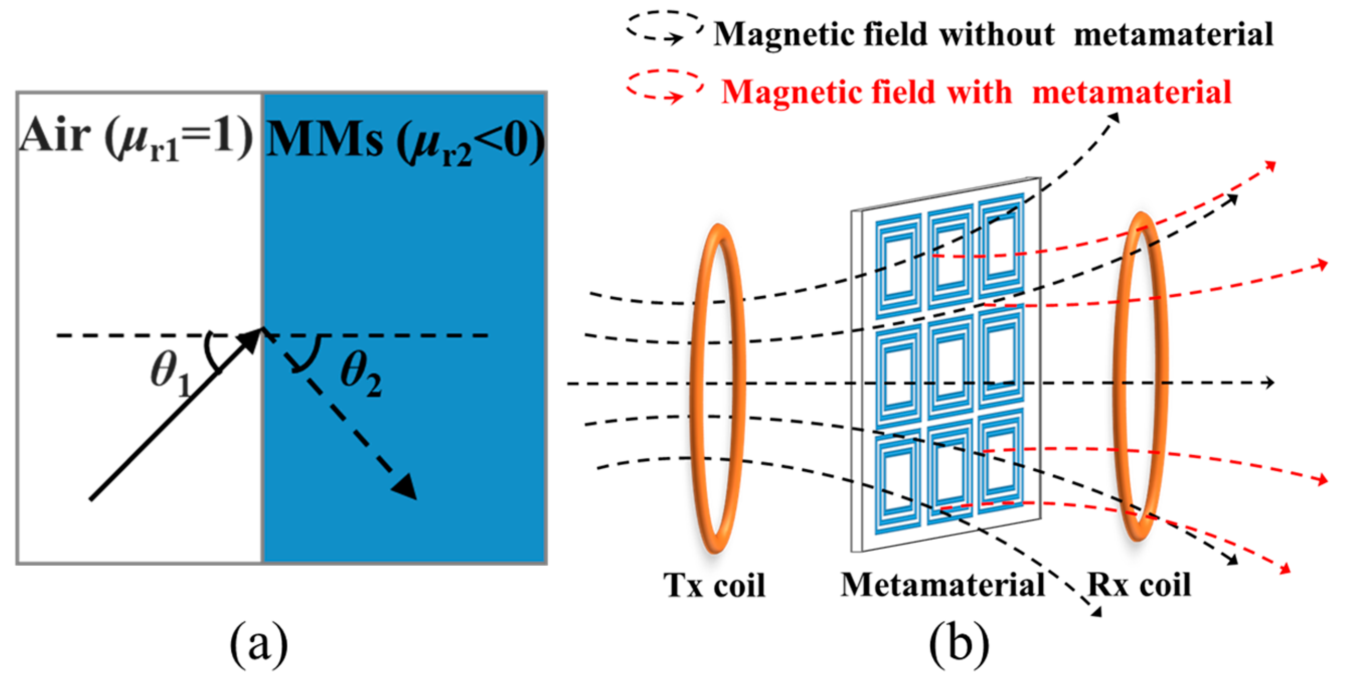
Here, θ1 and θ2 indicate the incident angle and reflection angle, respectively. The μr1 and μr2 are the relative permeability of air and MM, respectively. As depicted in Figure 3a, magnetic fields are bent toward the inside of coils by the magnetic boundary conditions when they pass through the MNM-MM. Then, the diverging magnetic field becomes a converging magnetic field by utilizing an MM medium, as shown in Figure 3b. Hence, the transfer distance and efficiency of a WPT system can be improved effectively.

2.2. Design of WPT System and MNM-MM

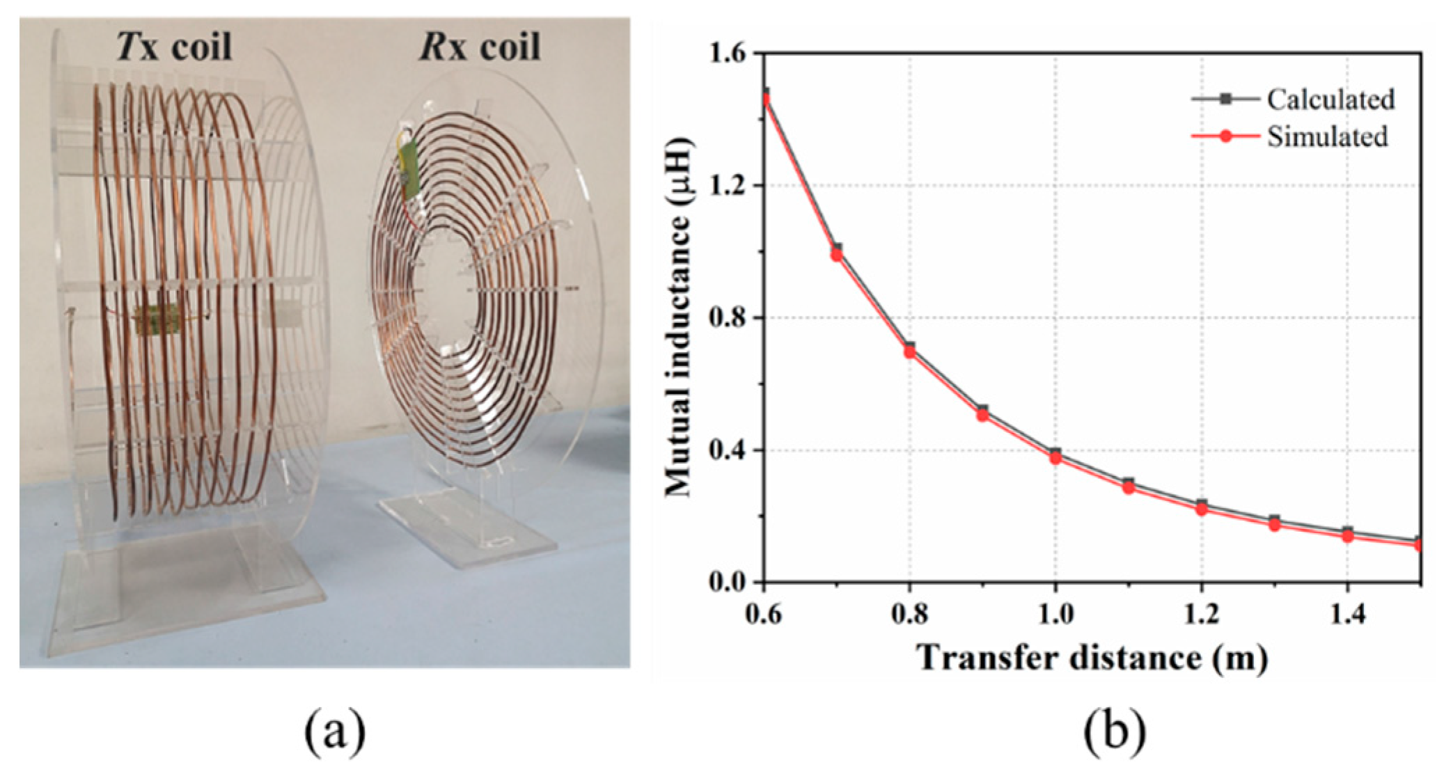
Based on the practical application scenario of wireless charging for unmanned equipment, an asymmetric four-coil system was designed and is described herein. The Tx coil was a helix coil. The Rx coil was designed as a planar spiral coil in order to make it more compact and allow it to be installed more easily on unmanned equipment. The diagram of two transmission coils is presented in Figure 4a. The transmission coils were all wound with a copper tube with a diameter of 4 mm, and the resonance frequency of 3 MHz was adjusted by the external compensation capacitor. The diameter of Tx coil was 50 cm, the number of turns was 10 and the turn spacing was 16 mm. The maximum diameter of Rx coil was 50 cm, the number of turns was 11 and the turn spacing was 15 mm. The drive coil and the load coil were both single-turn circular coils with a diameter of 50 cm. Table 1 lists the specific parameters of coupling coils. Figure 4b shows the variation curve of mutual inductance between Tx and Rx coils as the transfer distance dtr increases. The calculated results were obtained by the formula of coaxial mutual inductance of circular coils summarized in [21,22] and the superposition principle. The simulated and calculated results matched well, which verifies the correctness of the theoretical analysis.
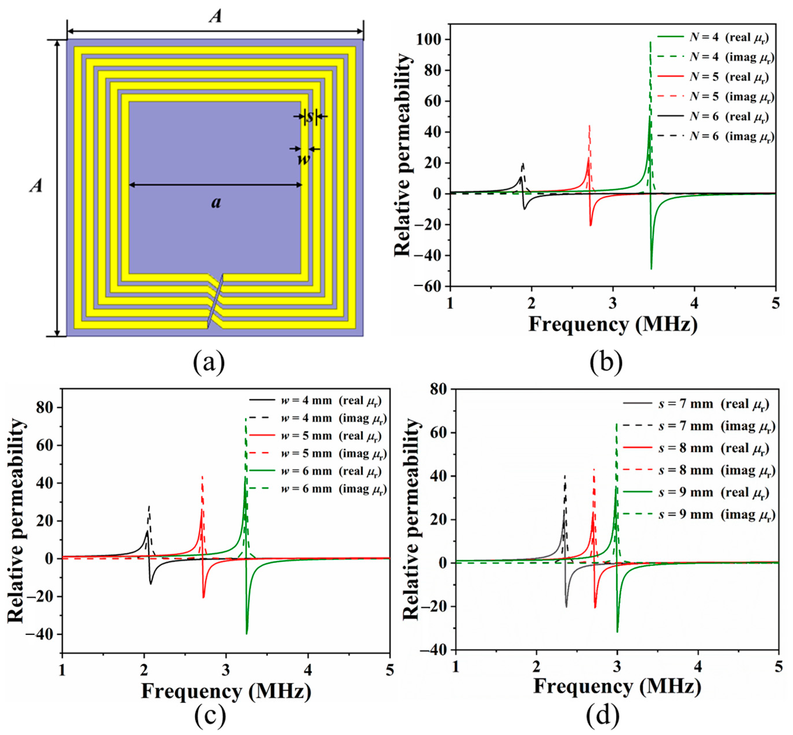
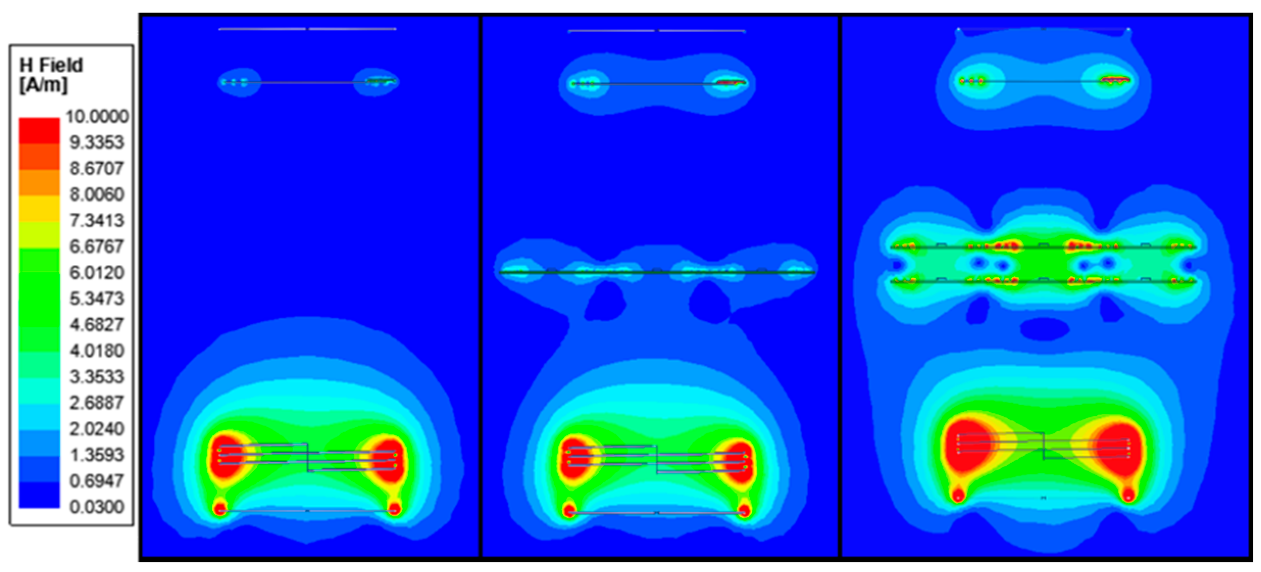
MMs are generally composed of a periodic arrangement of sub-wavelength structural units. By flexibly adjusting the geometric structure, size and other parameters of MMs, the electromagnetic field can be regulated and controlled. In general, 3D electromagnetic simulation software is used to optimize the design of MMs. Then, the obtained S-parameters are transformed into the relationship between relative permeability and frequency. In order to match the four-coil WPT system designed in this study, we chose an MM unit cell with a length of 200 mm and adopted an MM slab with 3 × 3 arrays. The MM unit structure is shown in Figure 5a, in which the substrate is an FR-4 plate with a thickness of 1.6 mm. Various structures were analyzed to achieve the desired MMs, as shown in Figure 5b–d. The resonant frequency of an MM unit cell changed correspondingly with the increase in the number of turns, the width and the spacing. We observed that an increase in the number of turns resulted in a decrease in resonance frequency, which was due to an increase in inductance. Additionally, the inductance increased with a decrease in width, lowering the resonance frequency. Furthermore, the spacing had less influence on resonance frequency. Therefore, in order to satisfy the relative permeability of –1 at 3 MHz, the structural parameters of MM were determined (the specific parameters are shown in Table 2). The gap gm between the slabs needs to be considered when two slabs are used. In order to study the focusing effect of MNM-MMs on an electromagnetic field, EM field simulator Ansoft HFSS was used. Figure 6 shows the comparison of magnetic field intensity distribution for systems with 0 – 2 metamaterial slabs. The results showed that the magnetic field intensity around the Rx coil increased when the MNM-MM slab was used. When there were two slabs, the magnetic field intensity increased more significantly, and there were strong surface waves on both sides of the MNM-MM slabs. This also proved that MNM-MMs can amplify evanescent waves, thus enhancing the magnetic coupling between Tx and Rx coils.

3. Experimental Results

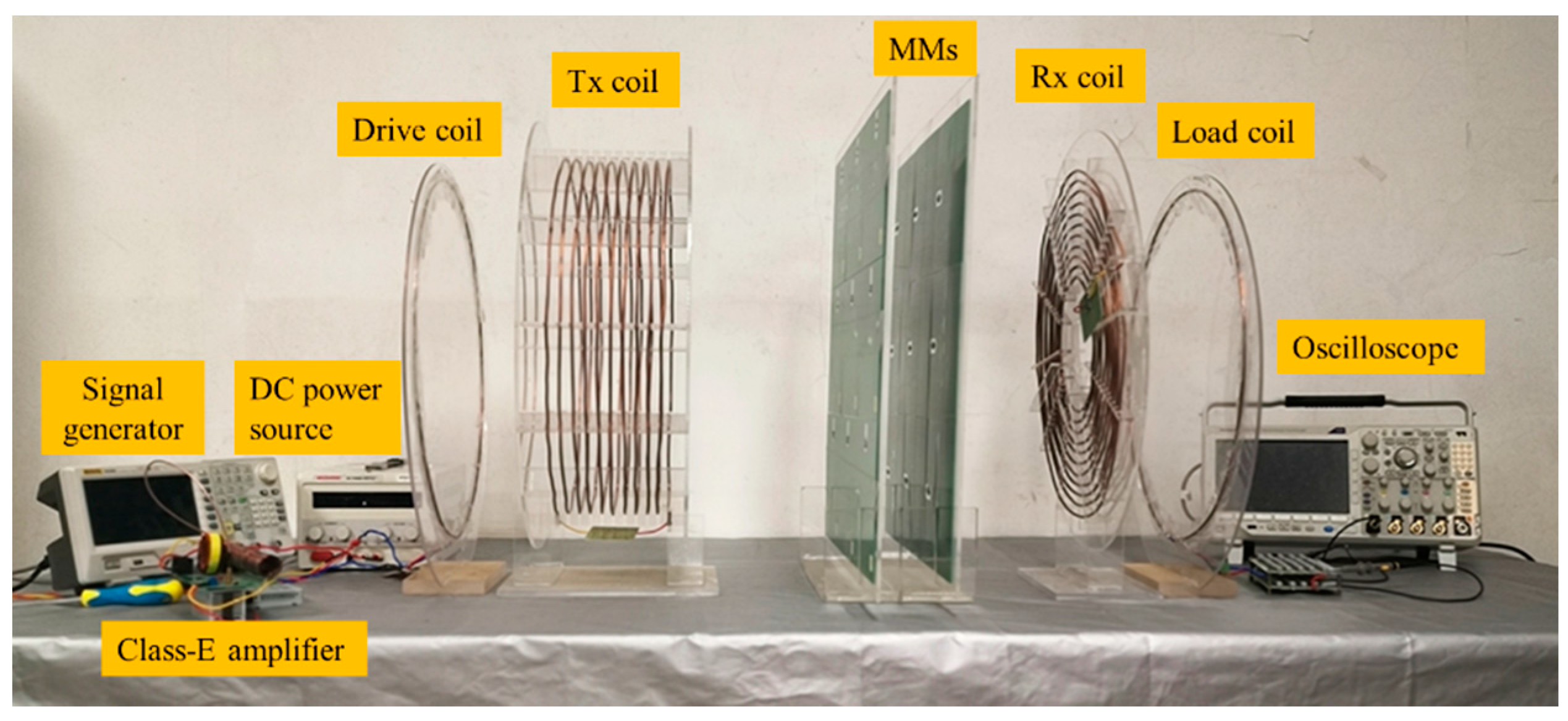
The experimental setup of a four-coil WPT system with MM slabs is shown in Figure 7, where they are all placed coaxially. The load coil was connected with a resistance of 10 Ω. Each MM unit cell was carefully tuned with a Vector Network Analyzer (AV-3656A) and Impedance Analyzer (MICROTEST-6632), and then the MMs with 3 × 3 arrays were assembled on an acrylic slab. The input power was fixed at 20 W in the experiments described here. The PTE could be easily calculated by voltage and current values displayed on the oscilloscope and DC power supply.
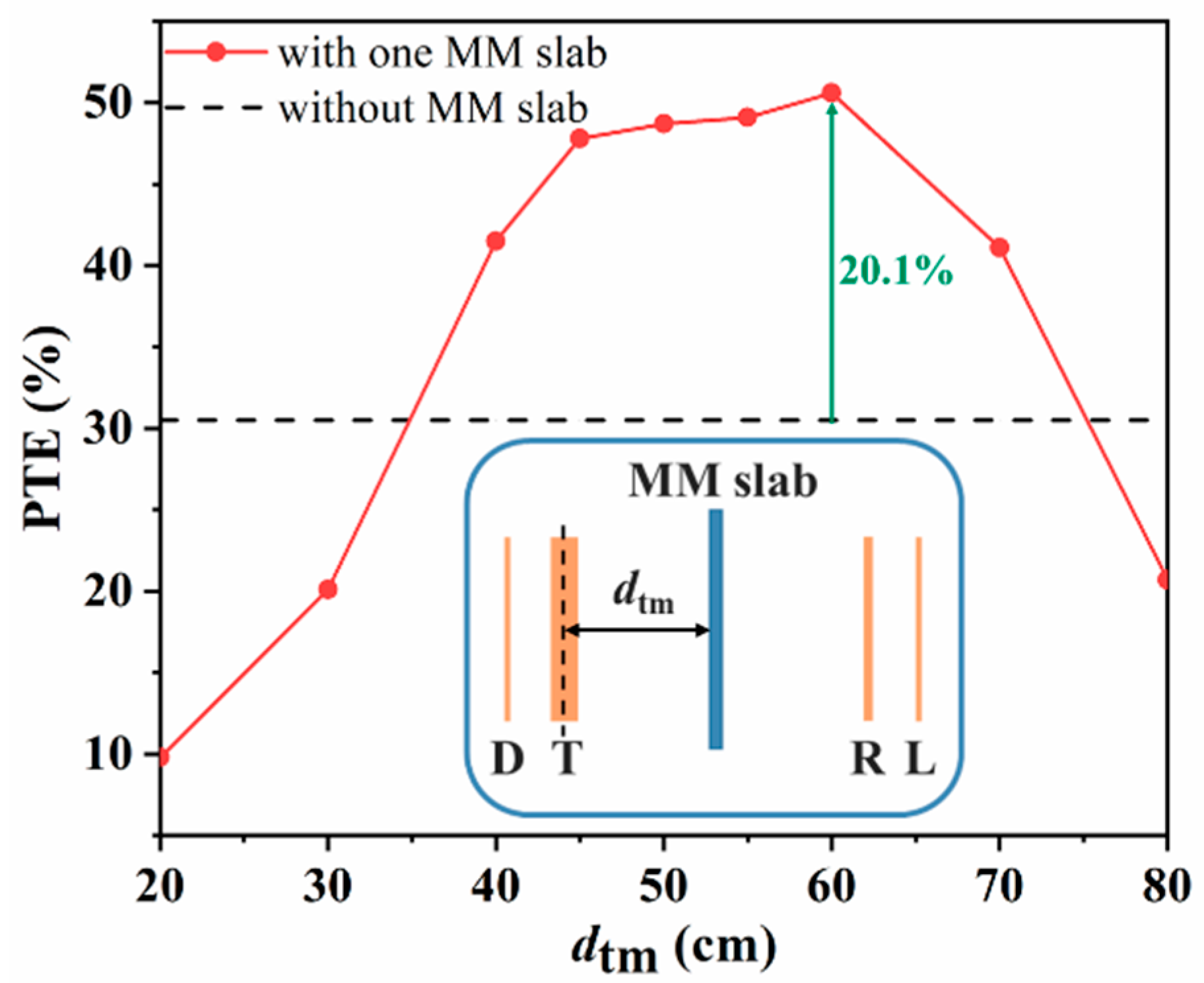
First, we explored the effect of the position of one MM slab between Tx and Rx coils on PTE. The experimental results obtained when the distance dtr between Tx and Rx coils was 100 cm are shown in Figure 8. The dtm is the distance between the MM slab and the Tx coil. It can be clearly seen from this figure that when dtm was in the range of 45–60 cm, the MM slab significantly improved PTE. PTE was the highest when dtm = 60 cm. At this time, compared to the system without MMs, PTE was improved by 20.10%. However, when the MM slab was close to the Tx or Rx coil, the efficiency was lower than that of the system without MMs. The results showed that MNM-MMs located in the central region could enhance the magnetic coupling and improve the PTE of a WPT system.
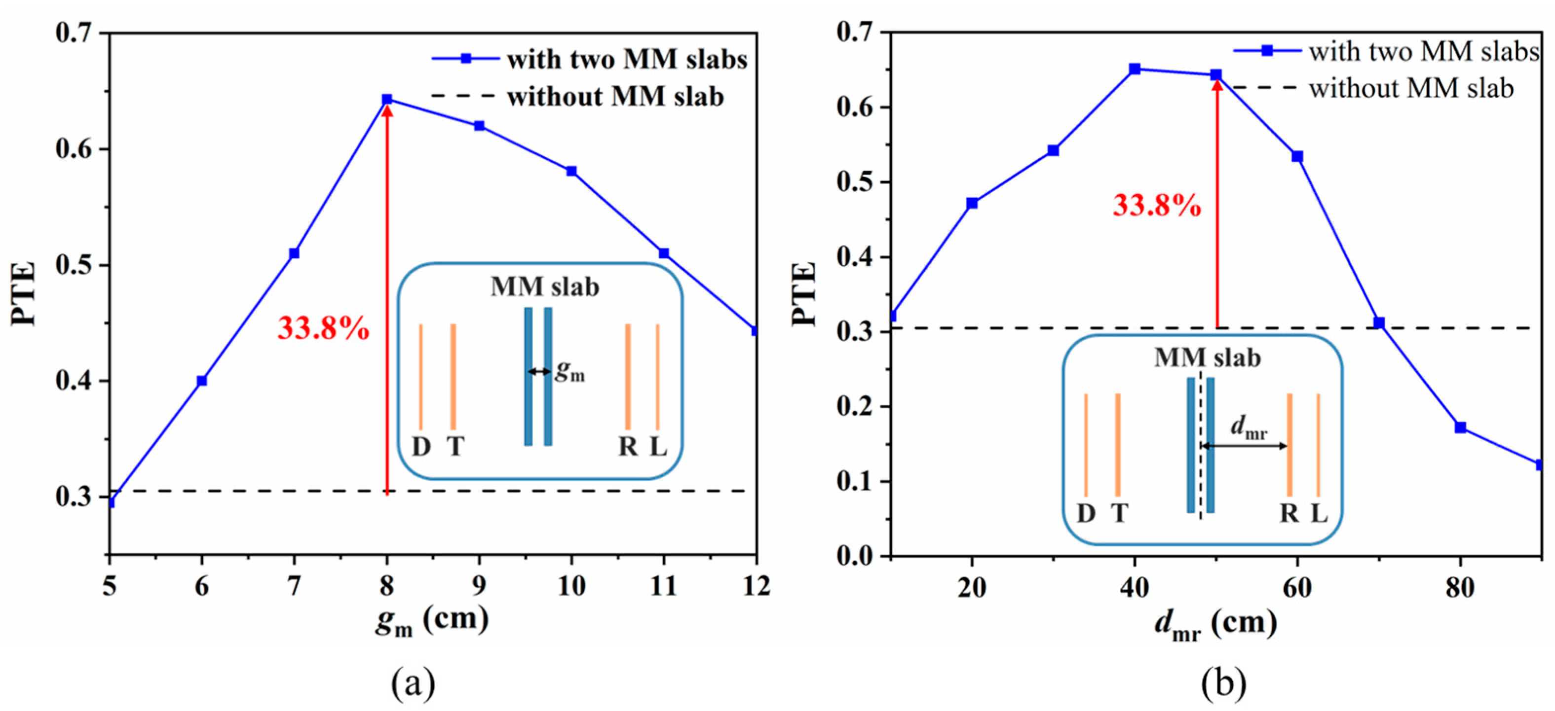
Based on the previous simulation results, in order to obtain a larger magnetic field for the Rx coil, we used a combination of two MNM-MM slabs. The spacing gm between two slabs is an important parameter. Figure 9a shows the change curve of PTE as gm increased when dtr = 100 cm and MM slabs were placed at dtm = 60 cm. The highest PTE was 64.33% at gm = 8 cm. Compared with the PTE of a system without MMs, it was improved by 33.83%. The experimental measurements showed that the maximum PTE was obtained at an optimal spacing. After determining the optimal gm, the influence of distance dtm between two MM slabs and Tx coil on PTE was explored, and the result is shown in Figure 9b. As was the case when using one MM slab, the PTE increased the most when the MM slabs were near the center position. In general, the magnetic field enhancement effect of two MM slabs was better than that of one MM slab, which can greatly improve the PTE of a WPT system. In this study, the PTE of a system with two slabs was improved by 13.73% when compared to the PTE of a system with one slab.
In addition, we also explored the relationship between PTE and drl at different transfer distances in a WPT system with two MM slabs. Figure 10 presents the results of PTE at the three distances: dtr = 80, 100 and 120 cm. The experimental results were obtained by placing two MM slabs with gm = 8 cm near the center position of the Tx and Rx coils. When dtr was fixed, the optimal load was realized by changing the distance drl between Rx and load coils so as to achieve maximum efficiency. It was observed that the optimal distance drl increased with the increase in dtr. When the dtr was 80, 100 and 120 cm, the PTE was increased by 22.32%, 33.83% and 28.75%, respectively. Therefore, the designed MMs were best able to improve efficiency in mid-range WPT systems.
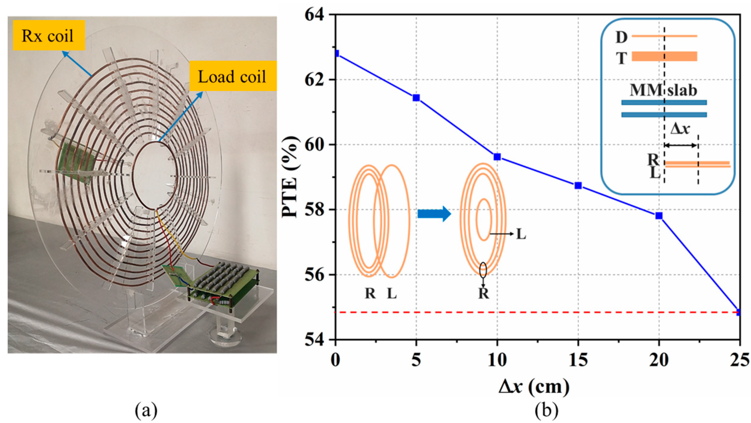
According to the above experimental results, it can be concluded that the focusing magnetic field performance of MMs designed in this study was the best when dtr = 100 cm, gm = 8 cm and dtm = 60 cm. In order to install the coils on unmanned equipment more flexibly and conveniently, we integrated the load coil into the Rx coil. According to the optimal situation at dtr = 100 cm, the load coil was optimized to be a single loop with a diameter of 15 cm. It was coaxially placed on the acrylic plate of the Rx coil, as shown in Figure 11a. The coil offset was inevitable during wireless charging, so the influence of offset distance of Rx and load coils on PTE was studied. The experimental results are shown in Figure 11b. The horizontal coordinate represents the lateral offset Δx, and the measurement step length is 5 cm. The PTE of the system without offset was 62.80%, which is close to the optimal efficiency of the previous experiment. When Δx = 25 cm, the PTE was 54.84%, which is only 7.96% lower than the PTE of the system without offset.
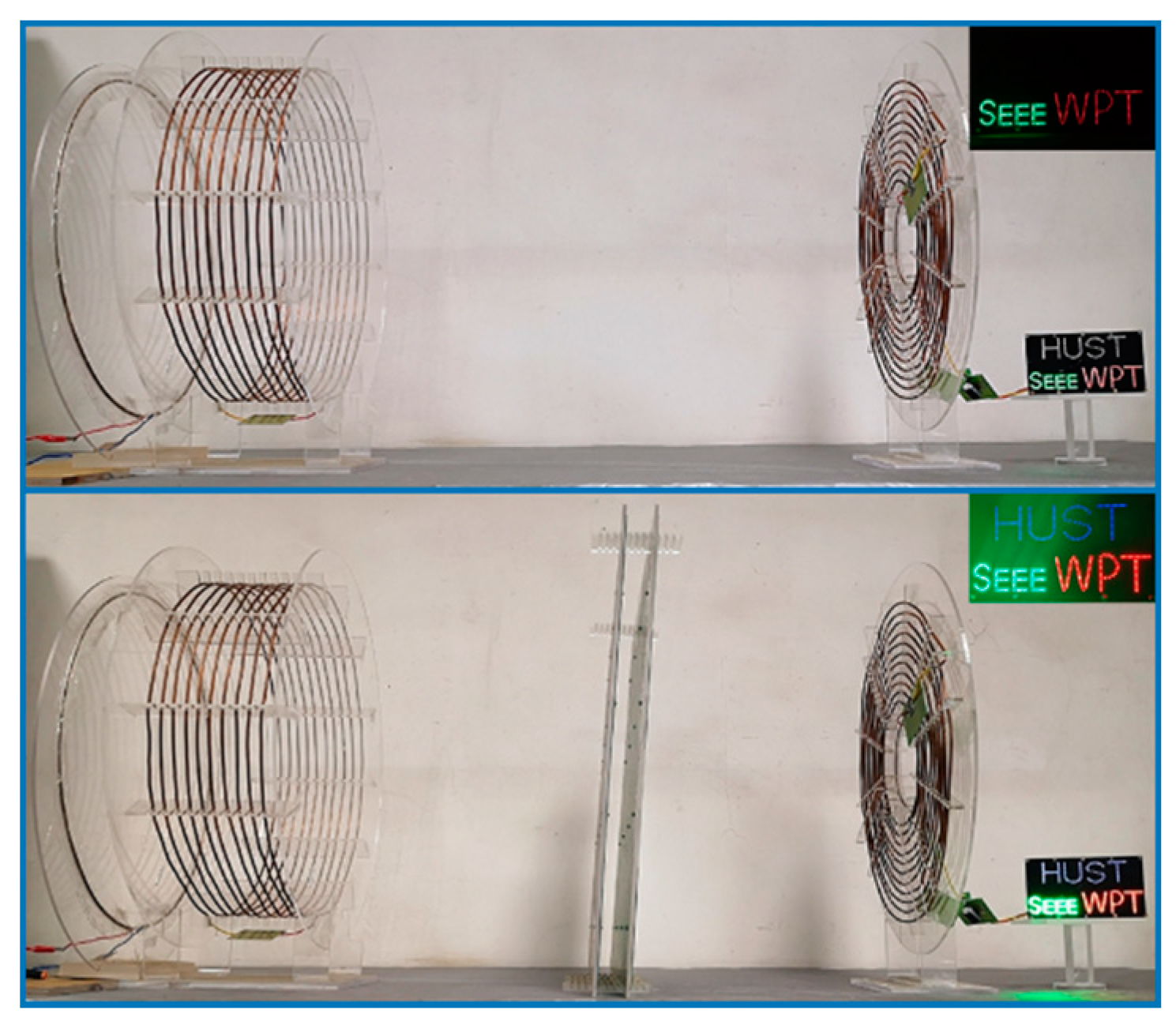
The above experimental results can be verified by using the equivalent circuit method proposed in [23]. Finally, an LED lamp panel was used to show the magnetic-field-focusing effect of the MM slabs more intuitively. Figure 12 clearly shows that the light of a WPT system without MM slabs was very weak, but it became brighter after using the MM slabs.
Transfer performances of the proposed WPT system with MNM-MMs are compared with previously reported performances in Table 3. According to the table, the proposed MNM-MMs in this study had unique advantages in improving the performance of medium-distance WPT.

4. Conclusions

In this work, we analyzed and designed an asymmetric WPT system with MNM-MMs. The principle shows that MNM-MMs can concentrate the magnetic field between the Tx and Rx coils, thus enhancing the PTE of the WPT system. In order to optimize PTE, the study was carried out by changing the position, number and spacing of MM slabs. PTE was the highest when MM slabs were placed near the center position of Tx and Rx coils. When two MM slabs were used, there was an optimal spacing gm that made the system most efficient. A WPT system with one MM slab improved PTE by 20.10%, and a WPT system with two MM slabs improved PTE by 33.83%. Therefore, the evanescent wave enhancement characteristics of two slabs are better than those of one slab. Based on this, we also explored the efficiency improvement capability of two MM slabs at different transfer distances. The results showed that PTE increased by 22.32%, 33.83% and 28.75% at distances of 80, 100 and 120 cm, respectively. Therefore, the designed MNM-MMs can make a WPT system more efficient in the mid-range distance. Furthermore, the Rx and the load coils were integrated, and the influence of their offset distance on PTE was explored. When the lateral offset distance was 25 cm, the PTE only decreased by 7.96%. Finally, we showed that the WPT system with MMs could increase the brightness of an LED lamp panel.
The WPT system designed in this study is suitable for mid-range distance transmission and would be especially useful for unmanned equipment (e.g., patrol robots). In order to reduce the occupied space, we will further study the compact design of integrating MMs into Tx or Rx.

Author Contributions

Y.Z. and X.T. conceived and designed the research; Y.Z. and C.L. wrote the original manuscript; M.L. reviewed and edited the manuscript; resources, C.R. and X.L.; formal analysis, R.L. and C.L.; visualization, Y.Z. and C.R. All authors have read and agreed to the published version of the manuscript.

Funding

Our work was supported by the National Key R&D Program of China (Grant No. 2018YFB0106300) and the “Climbing” Program of Huazhong University of Science and Technology.

Institutional Review Board Statement

Not applicable.

Informed Consent Statement

Not applicable.

Conflicts of Interest

The authors declare no conflict of interest.

References

  1. Hoang, H.; Lee, S.; Kim, Y.; Choi, Y.; Bien, F. An adaptive technique to improve wireless power transfer for consumer electronics. IEEE Trans. Consum. Electron. 2012, 58, 327–332. [Google Scholar] [CrossRef]
  2. Cai, C.; Wang, J.; Liu, R.; Fang, Z.; Zhang, P.; Long, M.; Hu, M.; Lin, Z. Resonant wireless charging system design for 110 kv high voltage transmission line monitoring equipment. IEEE Trans. Ind. Electron. 2019, 66, 4118–4129. [Google Scholar] [CrossRef]
  3. Liu, C.; Jiang, C.; Song, J.; Chau, K.T. An effective sandwiched wireless power transfer system for charging implantable cardiac pacemaker. IEEE Trans. Ind. Electron. 2019, 66, 4108–4117. [Google Scholar] [CrossRef]
  4. Basar, M.R.; Ahmad, M.Y.; Cho, J.; Ibrahim, F. Stable and high-efficiency wireless power transfer system for robotic capsule using a modified helmholtz coil. IEEE Trans. Ind. Electron. 2017, 64, 1113–1122. [Google Scholar] [CrossRef]
  5. Liu, M.; Fu, M.; Wang, Y.; Ma, C. Battery cell equalization via megahertz multiple-receiver wireless power transfer. IEEE Trans. Power Electron. 2018, 33, 4135–4144. [Google Scholar] [CrossRef]
  6. Ahn, D.; Hong, S. A study on magnetic field repeater in wireless power transfer. IEEE Trans. Ind. Electron. 2013, 60, 360–371. [Google Scholar] [CrossRef]
  7. Park, C.; Lee, S.; Cho, G.H.; Chun, T.M. Innovative 5-m-off-distance inductive power transfer systems with optimally shaped dipole coils. IEEE Trans. Power Electron. 2015, 30, 817–827. [Google Scholar] [CrossRef]
  8. Choi, B.H.; Thai, V.X.; Lee, E.S.; Kim, J.H.; Rim, C.T. Dipole-coil-based wide-range inductive power transfer systems for wireless sensors. IEEE Trans. Ind. Electron. 2016, 63, 3158–3167. [Google Scholar] [CrossRef]
  9. Pendry, J.B. Negative refraction makes a perfect lens. Phys. Rev. Lett. 2000, 85, 3966–3969. [Google Scholar] [CrossRef] [PubMed]
  10. Shelby, R.A.; Smith, D.R.; Schultz, S. Experimental verification of a negative index of refraction. Science 2001, 292, 77–79. [Google Scholar] [CrossRef] [PubMed] [Green Version]
  11. Pham, T.S.; Ranaweera, A.K.; Lam, V.D.; Lee, J.W. Experiments on localized wireless power transmission using a magneto-inductive wave two-dimensional metamaterial cavity. Appl. Phys. Express 2016, 9, 044101. [Google Scholar] [CrossRef]
  12. Cho, Y.; Kim, J.J.; Kim, D.H.; Lee, S.; Kim, H.; Song, C.; Kong, S.; Kim, H.; Seo, C.; Ahn, S.; et al. Thin pcb-type metamaterials for improved efficiency and reduced emf leakage in wireless power transfer systems. IEEE Trans. Microw. Theory Tech. 2016, 64, 353–364. [Google Scholar] [CrossRef]
  13. Pham, T.S.; Ranaweera, A.K.; Ngo, D.V.; Lee, J.W. Analysis and experiments on fano interference using a 2D metamaterial cavity for field localized wireless power transfer. J. Phys. D Appl. Phys. 2017, 50, 1–10. [Google Scholar] [CrossRef]
  14. Urzhumov, Y.; Smith, D.R. Metamaterial-enhanced coupling between magnetic dipoles for efficient wireless power transfer. Phys. Rev. B 2011, 83, 205114. [Google Scholar] [CrossRef]
  15. Huang, D.; Urzhumov, Y.; Smith, D.R.; Teo, K.H.; Zhang, J. Magnetic superlens-enhanced inductive coupling for wireless power transfer. J. Appl. Phys. 2012, 111, 064902. [Google Scholar] [CrossRef] [Green Version]
  16. Wang, B.; Teo, K.H.; Nishino, T.; Yerazunis, W.; Barnwell, J.; Zhang, J. Wireless power transfer with metamaterial. In European Conference on Antennas and Propagation; Palazzo dei Congressi: Rome, Italy, 2011. [Google Scholar]
  17. Ranaweera, A.L.A.K.; Duong, T.P.; Lee, J.W. Experimental investigation of compact metamaterial for high efficiency mid-range wireless power transfer applications. J. Appl. Phys. 2014, 116, 83–86. [Google Scholar] [CrossRef]
  18. Rong, C.C.; Tao, X.; Lu, C.H.; Hu, Z.; Huang, X.; Zeng, Y.Q.; Liu, M.H. Analysis and optimized design of metamaterials for mid-range wireless power transfer using a class-E RF power amplifier. Appl. Sci. 2018, 9, 26. [Google Scholar] [CrossRef] [Green Version]
  19. Jiang, C.; Chau, K.T.; Liu, C.; Lee, C.H.T. An overview of resonant circuits for wireless power transfer. Energies 2017, 10, 894. [Google Scholar] [CrossRef]
  20. Liu, S.; Chen, L.; Zhou, Y.; Cui, T.J. A general theory to analyse and design wireless power transfer based on impedance matching. Int. J. Electron. 2014, 101, 1375–1404. [Google Scholar] [CrossRef]
  21. Babic, S.; Sirois, F.; Akyel, C.; Girardi, C. Mutual inductance calculation between circular filaments arbitrarily positioned in space: Alternative to grover’s formula. IEEE Trans. Magn. 2010, 46, 3591–3600. [Google Scholar] [CrossRef]
  22. Conway, J.T. Inductance Calculations for Noncoaxial Coils Using Bessel Functions. IEEE Trans. Magn. 2007, 43, 1023–1034. [Google Scholar] [CrossRef]
  23. Rong, C.C.; Lu, C.H.; Tao, X.; Huang, X.; Zeng, Y.Q.; Liu, X.B.; Liu, M.H. Equivalent circuit method for Mu-Negative-Magnetic and Mu-Near-Zero metamaterials in wireless power transfer system. IET Power Electron. 2020, 13, 3056–3064. [Google Scholar] [CrossRef]
Figure 1. (a) Schematic diagram of a wireless power transfer (WPT) system with metamaterials (MMs). (b) The equivalent circuit diagram of a four-coil WPT system.
Energies 14 01348 g001
Figure 2. The relationship between power transfer efficiency (PTE) and k12 and k34.
Energies 14 01348 g002
Figure 3. (a) Magnetic boundary conditions of the mu-negative-magnetic (MNM) MM. (b) Magnetic field without and with metamaterial.
Energies 14 01348 g003
Figure 4. (a) The diagram of transmission coils. (b) Relationship between mutual inductance and dtr.
Energies 14 01348 g004
Figure 5. (a) The structure diagram of the MM unit cell. The relationship of relative permeability and resonance frequency depending on (b) the number of turns, (c) the width and (d) the spacing.
Energies 14 01348 g005
Figure 6. Comparison diagram of magnetic field intensity distribution for a system with one metamaterial slab, a system with two metamaterial slabs, and a system without metamaterial slabs.
Energies 14 01348 g006
Figure 7. Experimental setup of four-coil WPT system with MM slabs.
Energies 14 01348 g007
Figure 8. Relationship between PTE and dtm with one MM slab.
Energies 14 01348 g008
Figure 9. The PTE of a system with two MM slabs as a function of (a) gm and (b) dtm.
Energies 14 01348 g009
Figure 10. Measured PTE as a function of the drl.
Energies 14 01348 g010
Figure 11. (a) The setup of Rx and load coils. (b) Measured PTE as a function of the Δx.
Energies 14 01348 g011
Figure 12. WPT experiment with an LED lamp panel.
Energies 14 01348 g012
Table 1. Electrical parameters of coupling coils.
Coil TypeSelf-Inductance (μH)Resistance (Ω)Resonance Frequency (MHz)
Drive coil1.560.253
Tx coil65.403.803
Rx coil46.284.393
Load coil1.590.263
Table 2. Parameters of the MM unit cell.
SymbolParametersValue
ALength of side (mm)200
aInner side length (mm)116
wWidth (mm)5
sSpacing (mm)8
NTurn5
CSeries capacitance (pF)517
Table 3. MM-based WPT system performance comparison.
ReferenceFrequency (MHz)Distance (cm)PTE with MMs (%)PTE Improvement (%)Power (W)
[16]27.1250341880
[17]6.56071.19.7(Not used power supply)
10054.334.4
[19]2.810077.94.265
16050.9218.58
20020.119.13
This paper38072.0522.3220
10064.3333.83
12049.6328.75
Publisher’s Note: MDPI stays neutral with regard to jurisdictional claims in published maps and institutional affiliations.