
Investigation on the Torque Ripple Reduction Method of a Hybrid Electric Vehicle Motor


Abstract
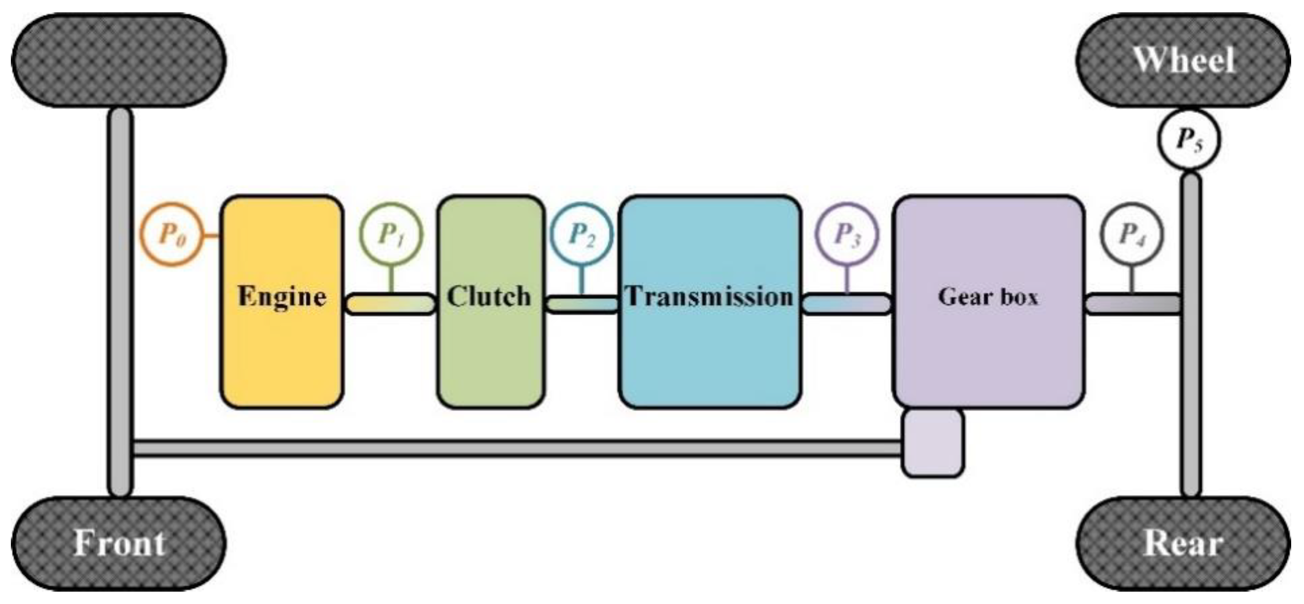
:1. Introduction
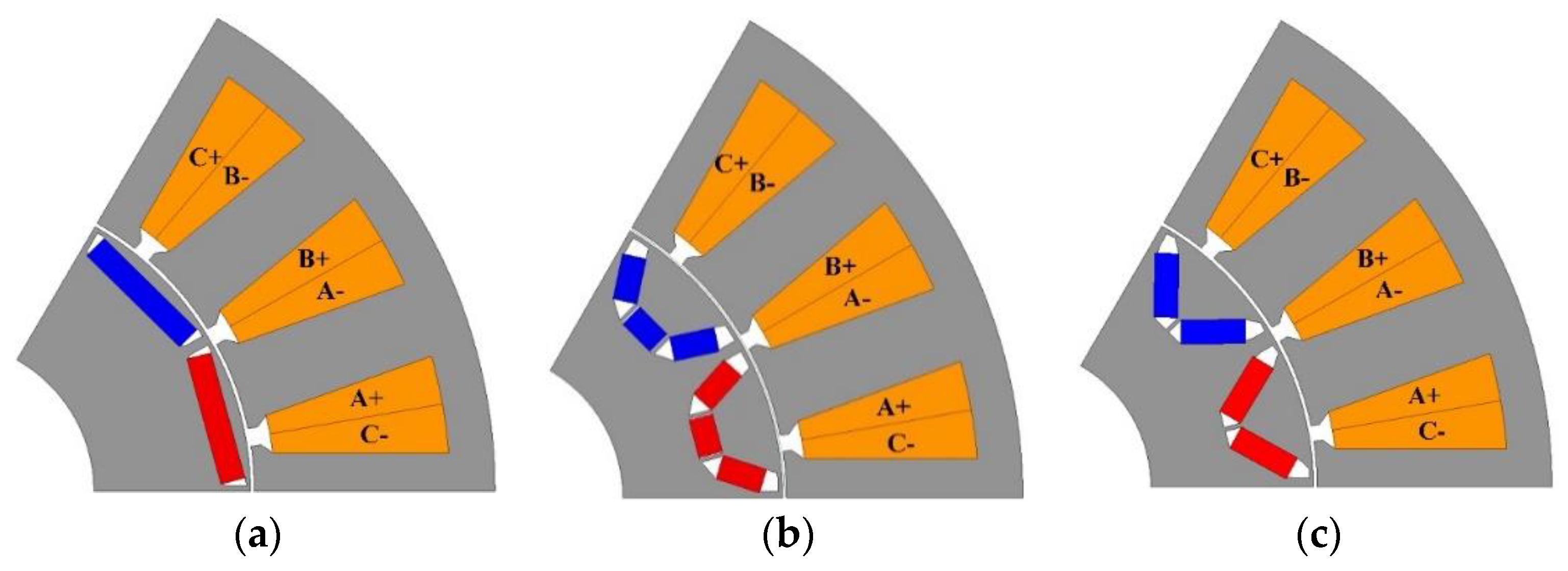
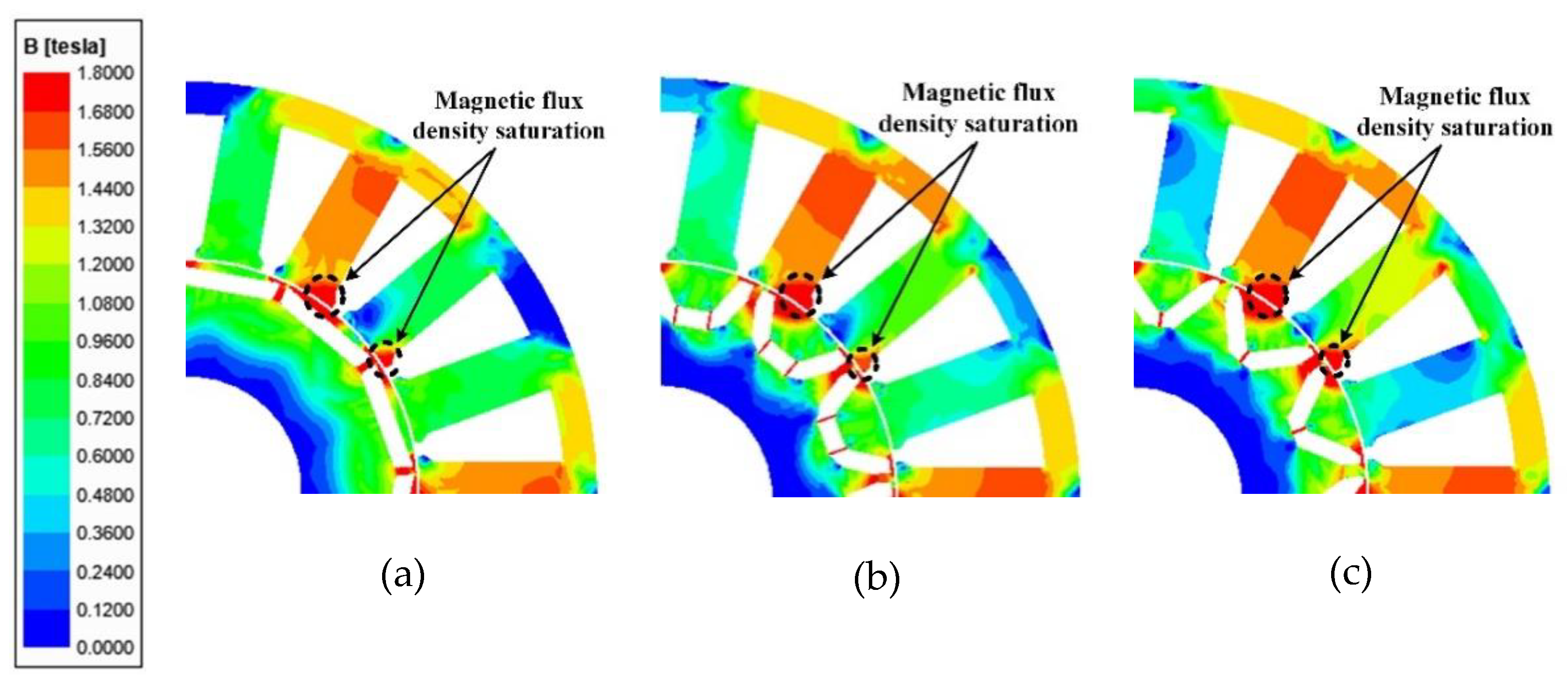
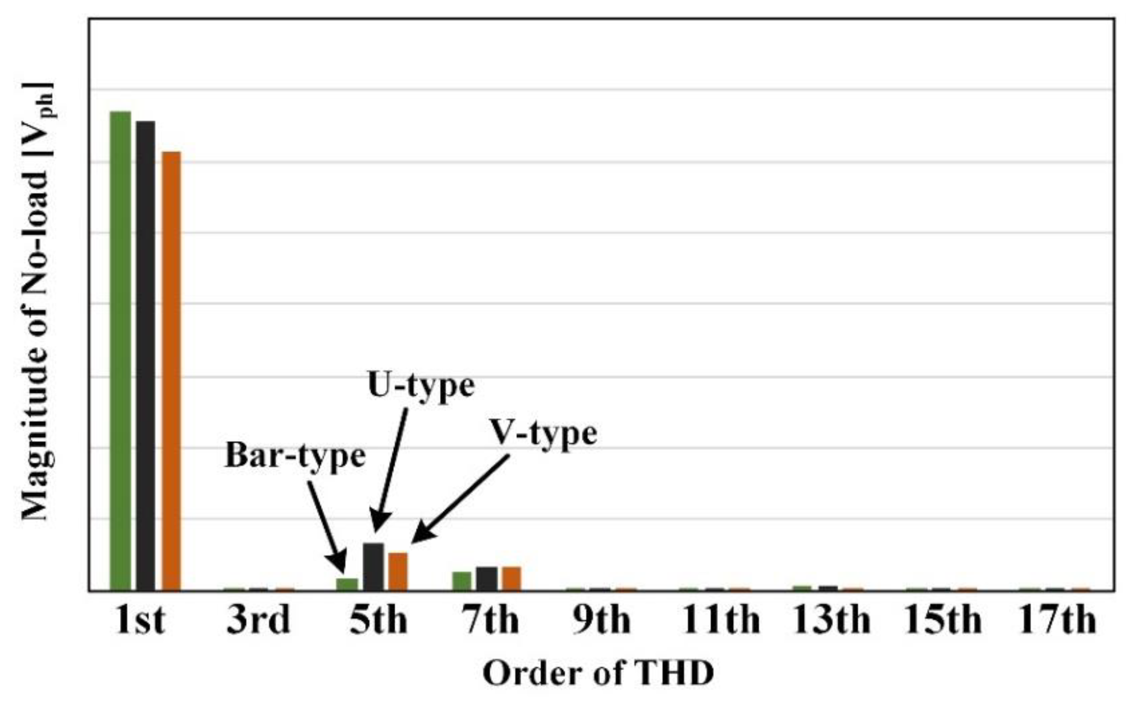
2. Analysis of Torque Ripple Characteristics by Various Rotor Shapes
3. Design of Barrier Shape to Reduce Torque Ripple
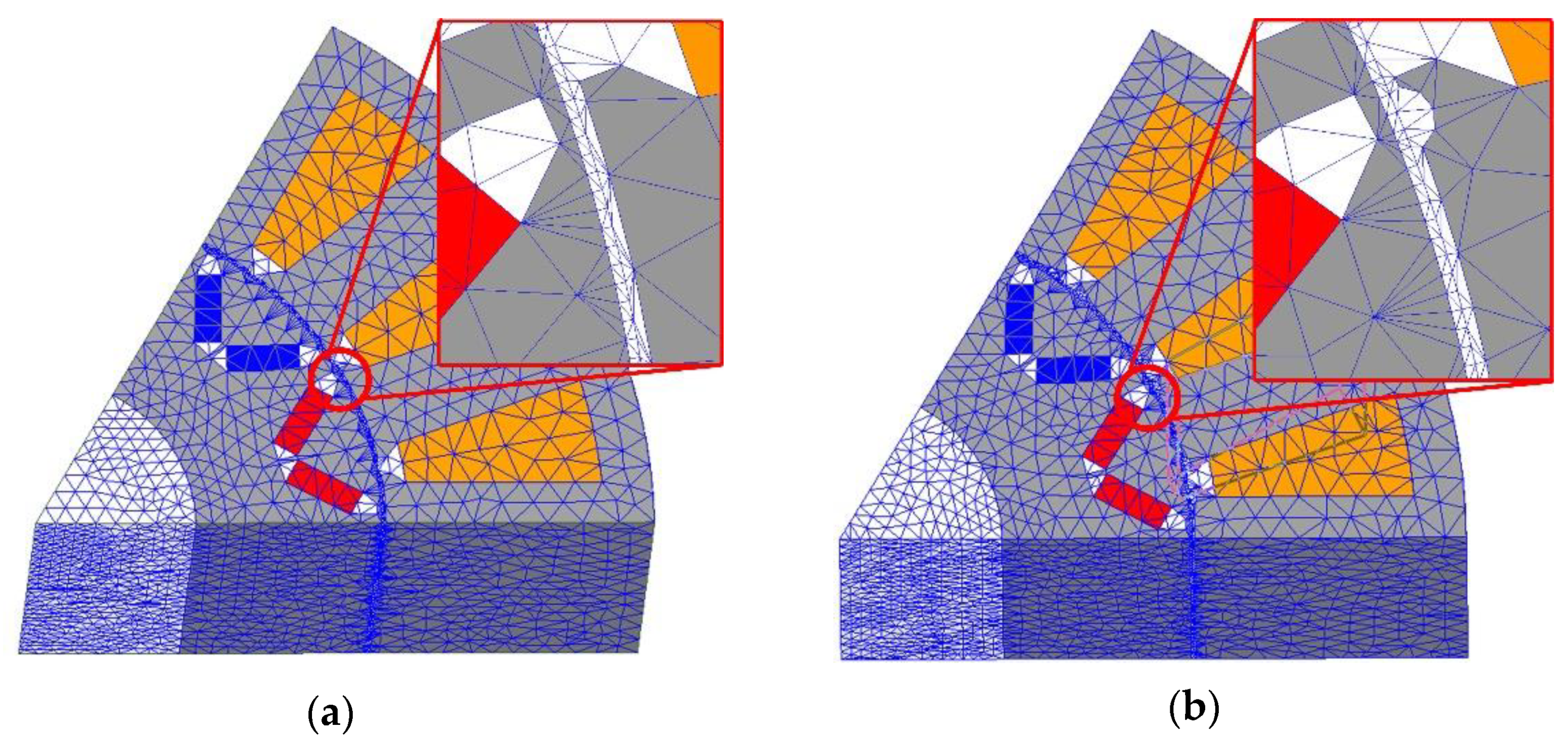
4. Design and Analysis of Wedge Skew
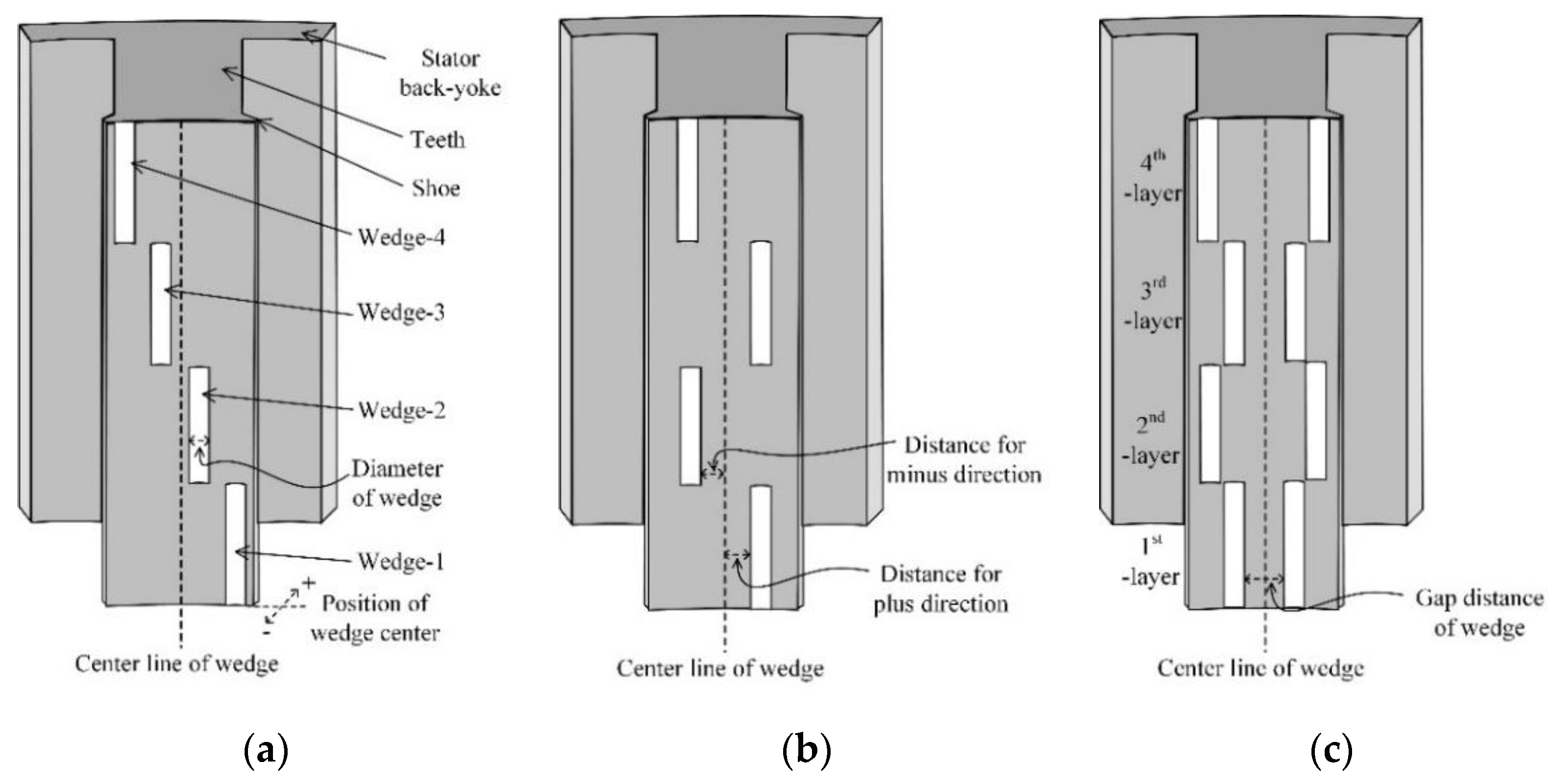
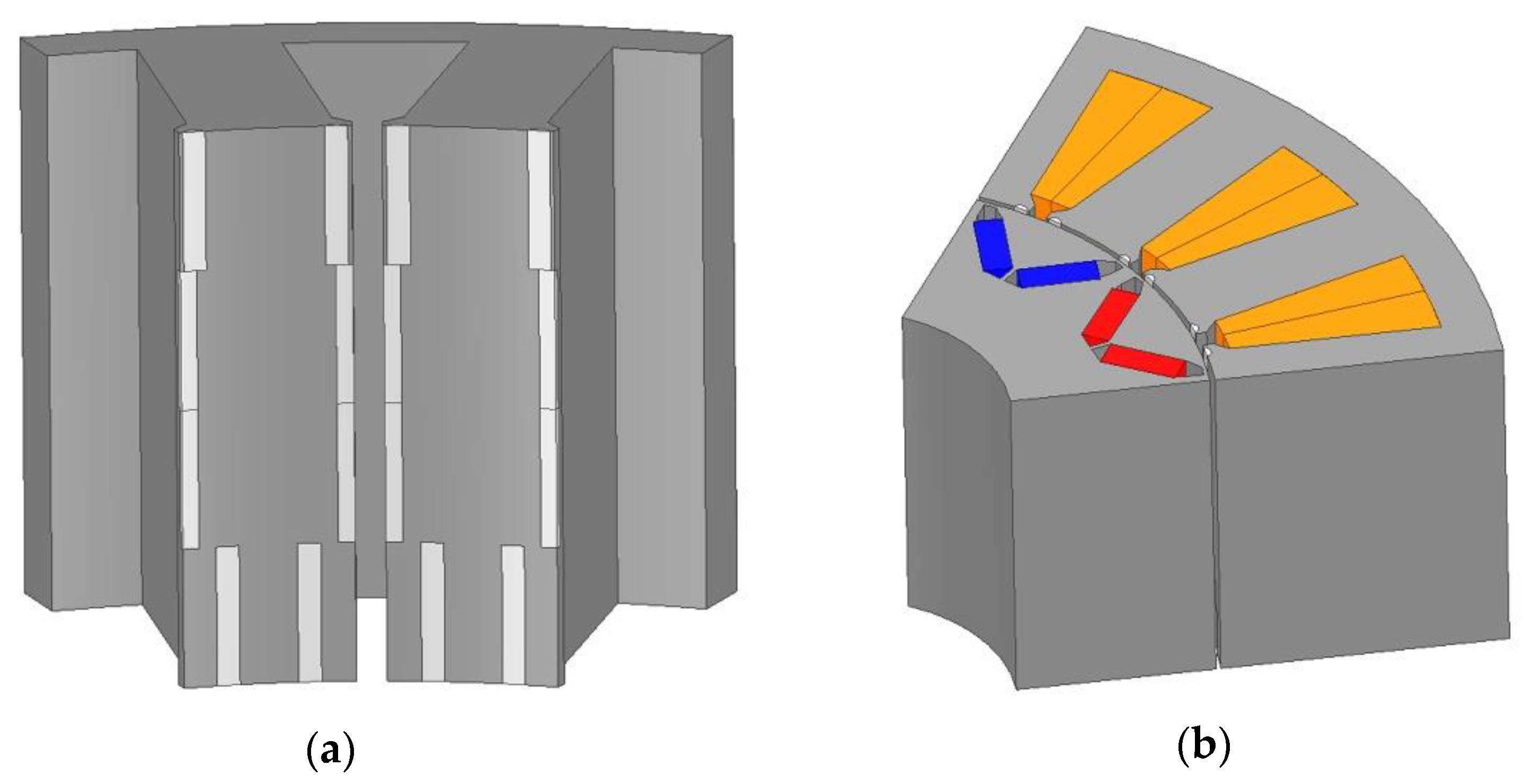
4.1. Conceptual Idea of Wedge Skew
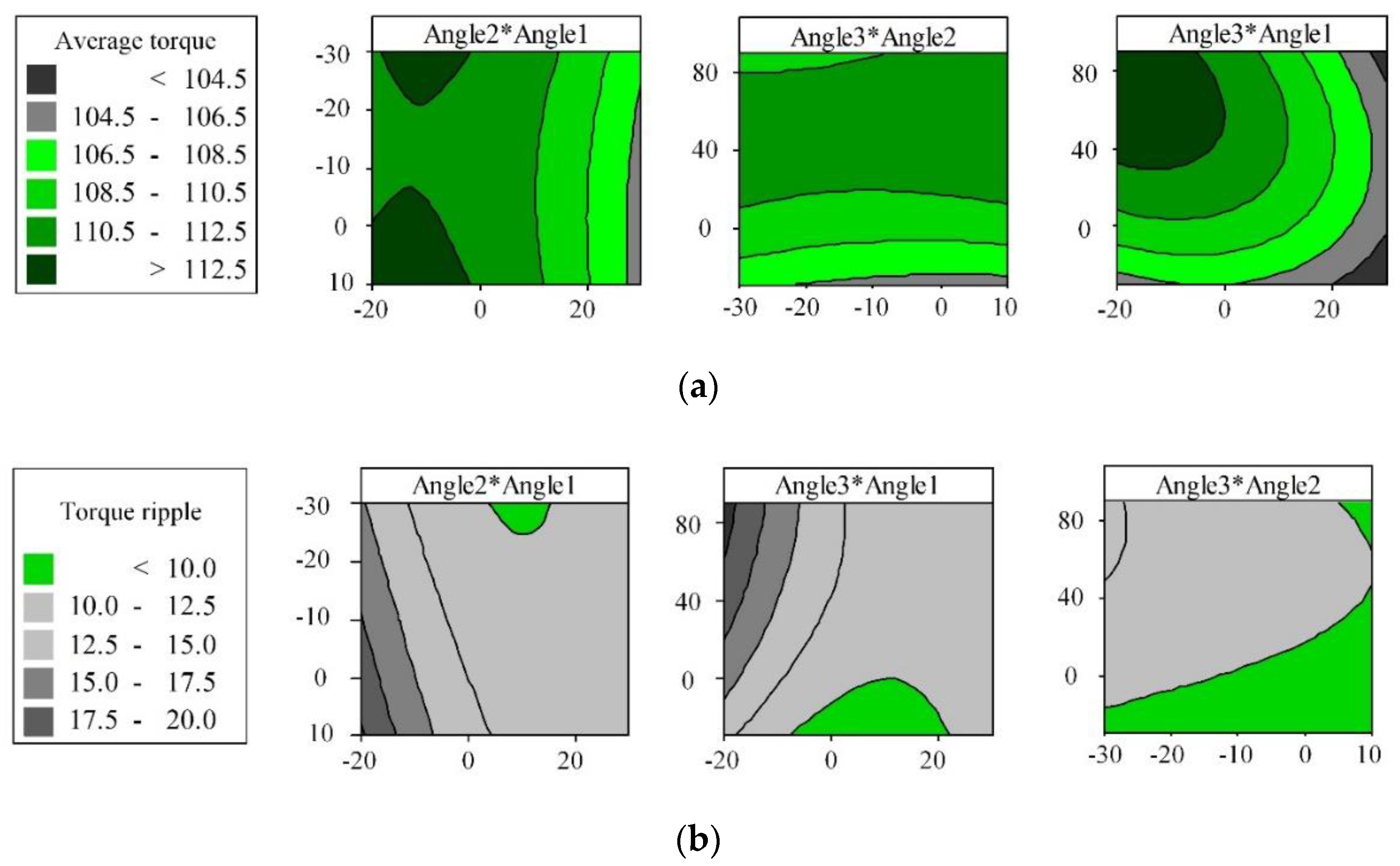
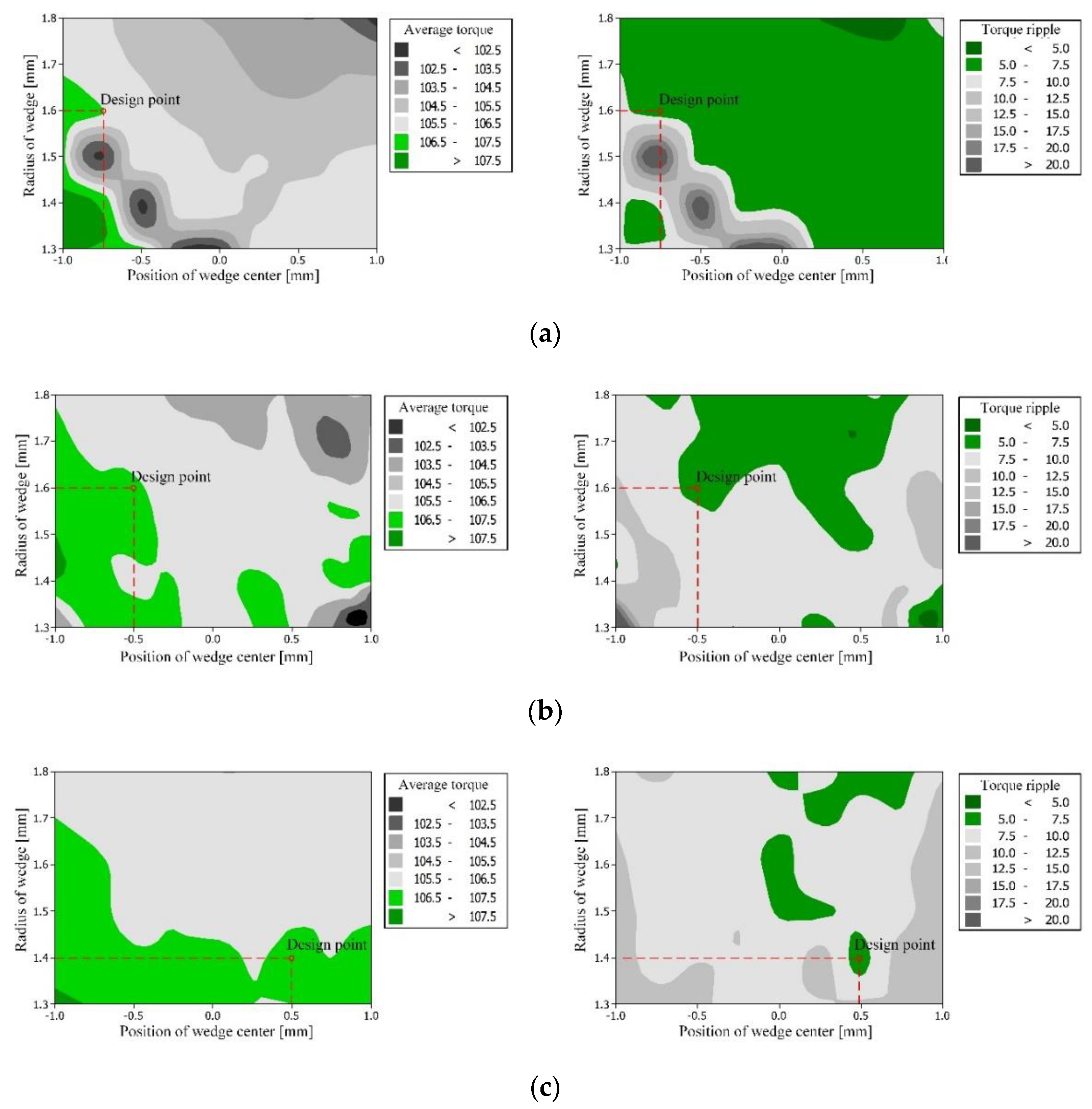
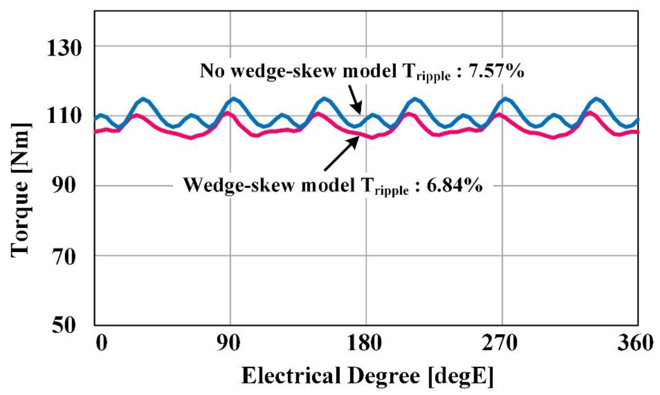
4.2. Result of Torque Ripple Characteristic with the Wedge Skew by 3D Finite Eelement Analysis
5. Conclusions
Author Contributions
Funding
Informed Consent Statement
Data Availability Statement
Conflicts of Interest
References
- Xue, Q.; Zhang, X.; Teng, T.; Zhang, J.; Feng, Z.; Lv, Q. A Comprehensive Review on Classification, Energy Management Strategy, and Control Algorithm for Hybrid Electric Vehicles. Energies 2020, 13, 5355. [Google Scholar] [CrossRef]
- Rao, Z.; Zhang, W.; Wu, G.; Zheng, J.; Huang, S. Characteristic Analysis and Predictive Torque Control of the Modular Three-Phase PMSM for Low-Voltage High Power Application. Energies 2020, 13, 5606. [Google Scholar] [CrossRef]
- Chu, G.; Dutta, R.; Pouramin, A.; Rahman, M.F. Analysis of Torque Ripple of a Spoke-Type Interior Permanent Magnet Machine. Energies 2020, 13, 2886. [Google Scholar] [CrossRef]
- Liu, H.C.; Kin, I.G.; Oh, Y.J.; Lee, J.; Go, S.C. Design of Permanent Magnet-Assisted Synchronous Reluctance Motor for Maximized Back-EMF and Torque Ripple Reduction. IEEE Trans. Magn. 2017, 53, 8202604. [Google Scholar] [CrossRef]
- Wei, C.; Hofman, T.; Caarls, E.I.; Iperen, R.V. A Review of the Integrated Design and Control of Electrified Vehicles. Energies 2020, 13, 5454. [Google Scholar] [CrossRef]
- Yang, T.; Kawaguchi, T.; Hashimoto, S.; Jiang, W. Switching Sequence Model Predictive Direct Torque Control of IPMSMs for EVs in Switch Open-Circuit Fault-Tolerant Mode. Energies 2020, 13, 5593. [Google Scholar] [CrossRef]
- Seo, U.J.; Chun, Y.D.; Choi, J.H.; Han, P.W.; Koo, D.H.; Lee, J. A Technique of Torque Ripple Reduction in Interior Permanent Magnet Synchronous Motor. IEEE Trans. Magn. 2011, 47, 3240–3243. [Google Scholar] [CrossRef]
- Dorrell, D.G.; Hsieh, M.F.; Knight, A.M. Alternative Rotor Designs for High Performance Brushless Permanent Magnet Machines for Hybrid Electric Vehicles. IEEE Trans. Magn. 2012, 48, 835–838. [Google Scholar] [CrossRef]
- Dai, M.; Keyhani, A.; Sebastian, T. Torque Ripple Analysis of A Permanent Magnet Brushless DC Motor Using Finite Element Method. In Proceedings of the IEEE International Electric Machines and Drives Conference, Cambridge, MA, USA, 17–20 June 2001. [Google Scholar]
- Tumbek, M.; Kesler, S. Design and Implementation of a Low Power Outer-Rotor Line-Start Permanent-Magnet Synchronous Motor for Ultra-Light Electric Vehicles. Energies 2019, 12, 3174. [Google Scholar] [CrossRef] [Green Version]
- Zhu, S.; Chen, W.; Xie, M.; Liu, C.; Wang, K. Electromagnetic Performance Comparison of Multi-Layered Interior Permanent Magnet Machines for EV Traction Applications. IEEE Trans. Magn. 2018, 54, 8104805. [Google Scholar] [CrossRef]
- Hwang, M.H.; Lee, H.S.; Cha, H.R. Analysis of Torque Ripple and Cogging Torque Reduction in Electric Vehicle Traction Platform Applying Rotor Notched Design. Energies 2018, 11, 3053. [Google Scholar] [CrossRef] [Green Version]
- Zhong, Z.; Jiang, S.; Zhou, Y.; Zhou, S. Active torque ripple reduction based on an analytical model of torque. IET Electr. Power Appl. 2017, 11, 331–341. [Google Scholar] [CrossRef]
- Islam, R.; Husain, I.; Fardoum, A.; McLaughlin, K. Permanent-Magnet Synchronous Motor Magnet Designs With Skewing for Torque Ripple and Cogging Torque Reduction. IEEE Trans. Indust. Appl. 2009, 45, 152–160. [Google Scholar] [CrossRef]
- Azar, Z.; Zhu, Z.Q.; Ombach, G. Influence of Electric Loading and Magnetic Saturation on Cogging Torque, Back-EMF and Torque Ripple of PM Machines. IEEE Trans. Mangn. 2012, 48, 2650–2658. [Google Scholar] [CrossRef]
- Islam, M.S.; Mir, S.; Sebastian, T.; Underwood, S. Design Considerations of Sinusoidally Excited Permanent-Magnet Machines for Low-Torque-Ripple Applications. IEEE Trans. Indust. Appl. 2005, 41, 955–962. [Google Scholar] [CrossRef]
- Baek, S.W.; Lee, S.W. Design Optimization and Experimental Verification of Permanent Magnet Synchronous Motor Used in Electric Compressors in Electric Vehicles. Appl. Sci. 2020, 10, 3235. [Google Scholar] [CrossRef]
- Han, S.H.; Jahns, T.M.; Soong, W.L.; Guven, M.K.; Illindala, M.S. Torque Ripple Reduction in Interior Permanent Magnet Synchronous Machines Using Stators With Odd Number of Slots Per Pole Pair. IEEE Trans. Ener. Conver. 2010, 25, 118–127. [Google Scholar] [CrossRef]
- Zohra, B.; Akar, M.; Eker, M. Design of A Novel Line Start Synchronous Motor Rotor. Electronics 2019, 8, 25. [Google Scholar] [CrossRef] [Green Version]
- Ito, Y.; Akatsu, K. Minimization of torque ripple in an Inset type Magnet Reluctance Motor with square wave current. In Proceedings of the 2018 XIII International Conference on Electrical Machines (ICEM), Alexandroupoli, Greece, 3–6 September 2018. [Google Scholar]
- Jang, H.; Oh, S.T.; Kim, H.; Jang, I.S.; Lee, J. Design and Analysis of a Novel Rotor Shape to Improve Power Performance. IEEE Trans. Appl. Supercond. 2020, 30, 5201304. [Google Scholar] [CrossRef]
- Jahns, T.M.; Soong, W.L. Pulsating torque minimization techniques for permanent magnet ac motor drives-a review. IEEE Trans. Indst. Electr. 1996, 43, 321–330. [Google Scholar] [CrossRef]
- Rao, J.; Gao, Y.; Li, D.; Qu, R. Performance Analysis of Interior Permanent Magnet Motor Using Overlapping Windings With Fractional Ratio of Slot to Pole Pair. IEEE Trans. Appl. Supercond. 2016, 7, 0610005. [Google Scholar] [CrossRef]
- Sun, H.Y.; Wang, K. Space Harmonics Elimination for Fractional-Slot Windings with Two-Slot Coil Pitch. IEEE Access 2019, 7, 106961–106972. [Google Scholar] [CrossRef]
- Wu, Z.Z.; Zhu, Z.Q.; Zhan, H.L. Comparative Analysis of Partitioned Stator Flux Reversal PM Machines Having Fractional-Slot Nonoverlapping and Integer-Slot Overlapping Windings. IEEE Trnas. Enrgy Conver. 2016, 31, 776–788. [Google Scholar] [CrossRef]
- Donato, G.D.; Capponi, G.; Rivellini, G.A.; Caricchi, F. Integral-Slot versus Fractional-Slot Concentrated-Winding Axial-Flux Permanent-Magnet Machines: Comparative Design, FEA, and Experimental Tests. IEEE Trans. Indust. Appl. 2012, 48, 1487–1495. [Google Scholar] [CrossRef]
- EL-Refaie, A.M. Fractional-Slot Concentrated-Windings Synchronous Permanent Magnet Machines: Opportunities and Challenges. IEEE Trans. Indust. Electr. 2010, 57, 107–121. [Google Scholar] [CrossRef]
- Wu, D.; Zhu, Z.Q. Design Tradeoff between Cogging Torque and Torque Ripple in Fractional Slot Surface-Mounted Permanent Magnet Machines. IEEE Trans. Magn. 2015, 51, 8108704. [Google Scholar] [CrossRef]
- Wang, K.; Lin, H. Modular Permanent Magnet Synchronous Machine with Low Space Harmonic Content. Energies 2020, 13, 3924. [Google Scholar] [CrossRef]
- Bianchi, N.; Bolognani, S.; Pre, M.D.; Grezzani, G. Design Considerations for Fractional-Slot Winding Configurations of Synchronous Machines. IEEE Trans. Indust. Appl. 2006, 42, 997–1006. [Google Scholar] [CrossRef]
- Bezerra, M.A.; Santelli, R.E.; Oliveira, E.P.; Villar, L.S.; Excaleira, L.A. Response surface methodology (RSM) as a tool for optimization in analytical chemistry. Talanta 2008, 76, 965–977. [Google Scholar] [CrossRef]


| Item | Value | Unit |
|---|---|---|
| Stator diameter | 270 | mm |
| Rotor diameter | 151 | mm |
| Air gap length | 1 | mm |
| Stack length | 74 | mm |
| Area of permanent magnet | 192 | mm2 |
| Number of poles | 12 | - |
| Number of slots | 18 | - |
| Type | Torque Ripple | Cogging Torque (Peak to Peak) |
|---|---|---|
| Bar-type IPMSM | 9.12% | 12.76 Nm |
| U-type IPMSM | 12.20% | 4.81 Nm |
| V-type IPMSM | 10.73% | 6.13 Nm |
| Type | Average Torque (Nm) | Torque Ripple (%) |
|---|---|---|
| A-type | 107.5 | 8.49 |
| B-type | 107.3 | 7.56 |
| C-type (3 layers) | 106.5 | 8.36 |
| C-type (4 layers) | 106.6 | 6.84 |
| C-type (5 layers) | 106.5 | 7.30 |
| Model | Average Torque (Nm) | Torque Ripple (%) | Cogging Torque (Nm) | THD (%) | Back-EMF (Vph) |
|---|---|---|---|---|---|
| Basic model | 107.1 | 10.75 | 6.13 | 10.1 | 43.4 |
| Wedge skew model | 106.6 | 6.84 | 6.40 | 4.89 | 42.8 |
Publisher’s Note: MDPI stays neutral with regard to jurisdictional claims in published maps and institutional affiliations. |
© 2021 by the authors. Licensee MDPI, Basel, Switzerland. This article is an open access article distributed under the terms and conditions of the Creative Commons Attribution (CC BY) license (http://creativecommons.org/licenses/by/4.0/).
Share and Cite
Jang, H.; Kim, H.; Liu, H.-C.; Lee, H.-J.; Lee, J. Investigation on the Torque Ripple Reduction Method of a Hybrid Electric Vehicle Motor. Energies 2021, 14, 1413. https://doi.org/10.3390/en14051413
Jang H, Kim H, Liu H-C, Lee H-J, Lee J. Investigation on the Torque Ripple Reduction Method of a Hybrid Electric Vehicle Motor. Energies. 2021; 14(5):1413. https://doi.org/10.3390/en14051413
Chicago/Turabian StyleJang, Hyungkwan, Hyunwoo Kim, Huai-Cong Liu, Ho-Joon Lee, and Ju Lee. 2021. "Investigation on the Torque Ripple Reduction Method of a Hybrid Electric Vehicle Motor" Energies 14, no. 5: 1413. https://doi.org/10.3390/en14051413