Abstract
This paper presents a proposal for a new type of regulator for switched reluctance motor (SRM) drives. The proposed regulator enables a significant extension of the rotational speed range and drive output power. This regulator is characterized by a complex structure, including two regulation modules: voltage and phase supply switch-on angle. The voltage module includes a proportional integral derivative (PID) voltage regulator. During its operation, the value of the phase supply switch-on angle and the width of the phase supply range are determined as a result of interpolation of the data previously determined in the simulation program. The other module contains the PID controller of the phase supply switch-on angle. The values of the angles included in the tables have been determined so as to ensure that the drive works with the greatest possible efficiency. The control method is determined based on the current operating parameters of the drive, i.e., torque and speed. The operation of the regulator was simulated in the MATLAB Simulink program. The regulator presented here was implemented in a field programmable gate array (FPGA). Tests of the regulator’s operation in the prototype system were carried out in the field of control of commutation angles.
1. Introduction: SRM Control Methods
Each switched reluctance motor (SRM) includes a rotor composed of a package of magnetic sheets. Therefore, its moment of inertia is much greater than in other motors such as brushless direct current motors (BLDCs) with permanent magnets in the rotor. The magnetic flux in SRMs is excited by phase currents. As a result, additional losses in the windings also reduce their efficiency slightly compared to BLDC machines [1,2,3]. However, their undoubted advantages include high starting torque value [4,5], good drive efficiency over a very wide speed range [6,7], no cogging torque from permanent magnets, and the potential for achieving very high rotational speeds unattainable in other types of machines. These are the only machines which reach the rated torque value very quickly, during positioning and start-up. Therefore, they are suitable for applications for which other types of machines are unsuitable. However, the wide speed range over which they can function requires the use of very fast control systems. The examples of such a controller intended for carrying out measurement tests based on a field programmable gate array (FPGA) device is presented in [8,9,10]. The disadvantage of the SRM are large torque pulsations, but they can be limited, for example, by appropriate control [11,12,13,14] or changing the cross-sectional shape [15,16].
The potential for shaping phase current waveforms through the regulation of supply voltage and commutation angles enables smooth operation even at low speeds. However, the non-linear mechanical characteristics, similar to those of serial DC motors, cause significant speed fluctuations when the machine load changes. For stabilization, it is necessary to use complex regulators [17,18,19,20,21]. Regulators used in drives with typical DC motors do not allow for optimal SRM operating conditions. One of the basic advantages of SRMs is the ability to adjust the commutation conditions to the operating point, which is impossible in typical DC motors with mechanical commutators. Thanks to the option of changing the commutation angle [22,23], SRMs have much better operating parameters compared to DC motors, such as high efficiency over a very wide speed range and a wider range of speed regulation.
In SRM drives, the electronic commutators enable optimal adjustment of the commutation angle to the motor operating point. Regulation of the supply voltage alone does not permit the proper use of these properties. In solutions where the only parameter to change is the supply voltage, and where the machine works at constant values of commutation angles, the values of these angles are most often selected for the rated operating point or in order to obtain favorable parameters over the widest possible range of speeds and loads. In such cases, a constant average value of the commutation angles is assumed for the entire speed range. However, this approach degrades drive parameters such as efficiency and limits the speed control range. Due to their simplicity and low cost, such control solutions are used only in low-power drives.
Much better drive properties can be obtained by adjusting the commutation angle values to the machine operating points [22,23,24]. In many cases, a simple and effective solution is the dependence of the commutation angles on the rotational speed. However, this approach does not enable the full advantages of the machine’s capabilities in all cases. It is useful where there is a fixed dependence of load torque on speed. An example of this type of a drive is a fan, where each speed corresponds to a specific value of load torque. In such drives, where the values of commutation angles are made dependent on speed, they are indirectly dependent on torque. By changing the values of commutation angles in accordance with this dependence, it is possible to achieve optimal values of fan operating conditions over the entire speed range. Additionally, this extends the speed range in comparison to drives based on simpler control algorithms [25,26,27,28,29].
However, there are a wide range of applications in which the load torque is not a fixed function of speed, e.g., in vehicles [30,31,32,33,34,35,36], where the speed, set by means of changing the supply voltage, depends not only on the voltage and commutation angles but also on external factors such as load torque. At the same control parameters, different speeds will be obtained when the vehicle moves along a flat road and when it drives up a hill [4]. In this case, the optimal values of the commutation angles depend not only on the speed but also on the motor torque value. In such cases, it is necessary to account in the control process for the dependence of the commutation angles on two parameters.
Depending on the application and drive characteristics, one of the following two approaches can be used: selection of either a simplified control algorithm, or a more complex version that enables the optimization of all drive parameters over the entire range of speed and load changes. In order to develop such a control algorithm, it is necessary to determine the optimal dependences of these control parameters on the speed and torque of the motor. Such tests can be carried out with calculation methods using a mathematical model of the drive.
Such dependencies should be used in the control process. In order to use the full speed range of the SRM drive, the controller should consider two control ranges. The first is a voltage regulation at optimal commutation angles dependences, at a low-speed range. This range ends when the rated voltage is reached. In second speed range, further speed regulation is possible by regulation commutation angles at constant values of voltage. In this work, a regulator of this type is presented.
Most existing SRM drives limit speed control to voltage regulation mode [25,37]. However, it is possible to extend this range. Obtaining a higher speed is possible through application of an appropriate adjustment of the commutation angles at the rated value of the motor supply voltage. One important advantage of this method of control is the potential for increasing the drive speed while maintaining a constant torque value, i.e., increasing the drive power in the high-speed range. However, it is necessary in this regulation range to maintain a relationship between the value of the switch-on angle on the phase supply and the width of the angular phase supply range. This is necessary in order to obtain a high level of efficiency for the drive. This method of speed control is not usually used due to the complicated control method required. In order to apply this range of regulation, typical voltage regulators cannot be used. A controller of this type must enable the adjustment of two parameters, depending on the instantaneous speed and torque of the motor. In the lower speed range, the voltage regulator should work, and, after exceeding the set parameters of the motor operation, the angle regulator should start working. Depending on the operating state of the motor, in order to obtain a high level of efficiency for the drive over the entire operating range, it is necessary to set the appropriate values of the switch-on angle and the width of the phase supply angular range. During the operation of the voltage regulator module, whilst during the operation of the phase supply switch-on angle regulator, it is necessary to select the appropriate width of the phase supply angular range. Similar operating points of the drive can be obtained at many different combinations of supply voltages and commutation angles, therefore it is necessary, in order to obtain a high level of drive efficiency, to determine the values of these parameters in advance. This paper presents a proposal for a new regulator structure, taking into account the presented assumptions, and demonstrates the method of its implementation in the FPGA system.
Section 2 discusses the mathematical model designed for calculating drive characteristics. The method of its implementation in the simulation program is presented in Section 3. Prior to calculation of the motor characteristics, the correctness of the calculation results was verified by comparing them with the measurement results. Close convergence of the results made it possible to conduct further analysis of the regulator’s operation based on the simulation results.
Section 4 then presents the proposed structure of the controller in which the calculated characteristics of the drive were used. These characteristics describe the dependences of the control parameters on the speed and torque, enabling a high level of efficiency for the drive.
Section 5 presents the method of implementing the controller in a prototype system, in which an FPGA device was used as the control unit. The controller was implemented in the form of a specialized logical structure. The characteristics of the drive set out in Section 4 were transformed into a form enabling their implementation in a programmable device. Then, the results of the regulator operation correctness tests are presented. The measurement values were obtained by monitoring the changes in the commutation angles in the FPGA and comparing them with the results of the simulation.
Section 6 summarizes the results achieved and briefly presents directions for further work.
2. Mathematical Model of the Drive
The mathematical model of the drive was formulated using the Lagrange method. In the simulation model, a hybrid method was used, using the transformation of the flux Ψ (θ, i) relationship calculated in finite element method (FEM) to the form current i (θ, Ψ), according to the Hamilton method [38,39,40,41]. Due to the large number of calculations, simplifications were adopted in the model. Neither magnetic couplings between the motor windings nor motor core losses were included in the calculations.
The Lagrange function and virtual work δA for the SRM motor is as follows:
The mathematical model was formulated on the basis:
The electromagnetic torque of an SRM motor is:
The final form of the model equations is defined as (5) and (6):
where D is the coefficient of losses in rotational motion, i, ik are the phase currents, J is the rotor moment of inertia, R, Rk are the resistance values of the phase windings, Te is the electromagnetic torque, TL is the load torque, v, vk are the voltages of the phases, x is the vector of generalized coordinates, θ is the rotor position angle, and Ψk (θ, ik) is the magnetic flux associated with the kth phase.
The motor was powered from a typical SRM power supply system consisting of asymmetric H-type transistor half-bridges. All phase windings were supplied with unipolar voltage from a separate half-bridge.
During the drive operation, three states of the power supply system were taken into account:
- -
- The power supply state in which the transistors are switched on when the switch-on angle position is reached:
- -
- The idle loop state, to which the system is switched during the pulse width modulation (PWM) state and in the current limitation mode:
- -
- And the state of energy return to the source, in which the system is switched on when the switch-off angle position is reached:where V is the supply voltage, vT is the source drain transistor voltage, and vD is the diode voltage.
3. Simulation of the Drive
3.1. Determination of Model Parameters
The calculations were carried out for a drive with a three-phase SR motor supplied from a 230 V power converter. The rated motor power was 750 W at 3000 rpm. Magnetostatic calculations of motor parameters were performed in the FEMM program. Figure 1 shows its basic characteristics as obtained from calculations and measurements for verification of the motor model. Full motor characteristics determined in the FEMM program were used for calculations in the simulation program.
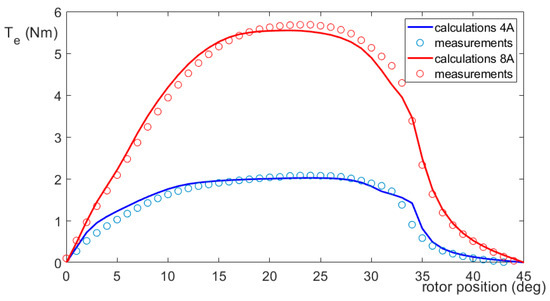
Figure 1.
Calculated and measured characteristics of electromagnetic torque Te.
The simulation program was developed in the MATLAB Simulink environment. In the simulation program, the motor phases were modelled in the form of three identical modules to which the rotor position angle signal, offset by 120 degrees, was connected. This enabled calculations to be made for all phases using the same data, obtained from magnetostatic calculations. Current and electromagnetic torque values during the simulation for instantaneous values of magnetic flux and rotor position angle were determined by interpolation of these data with second-degree spline functions and extrapolation with linear functions.
The motor simulation model was based on two data tables: dependence of the phase current on the magnetic flux and the rotor position angle, and the electromagnetic torque from the phase current and rotor position angle [42], presented in Figure 2.
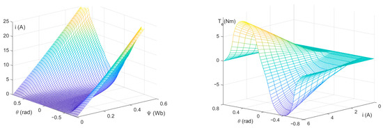
Figure 2.
The dependences of the phase current i on the magnetic flux Ψ and the rotor position angle θ, and the motor electromagnetic torque Te on the phase current i and the rotor position angle θ.
3.2. Determination of Control Characteristics
The model, shown in Figure 3, consisted of three main modules. The SRMotor module included a motor model based on the previously presented current and torque relationships. The Commutators module determined the angular range of the phase supply. The motor was powered in unipolar mode from a typical SRM power supply system consisting of asymmetrical half-bridges, which was the PowerSupplySystem module. The Measurement module enabled the determination of average and RMS values of the voltages, currents, and torque. The other modules were used to define the values of angles and load torque.
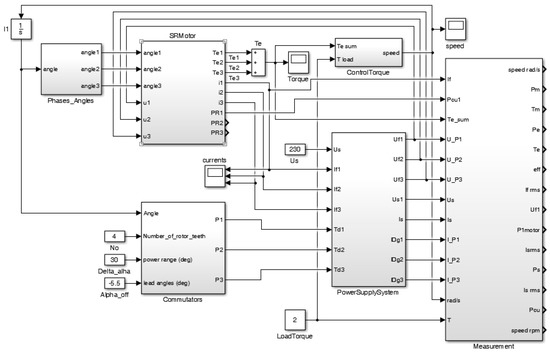
Figure 3.
Simulation model of the switched reluctance motor (SRM) drive.
In addition to the motor and power supply modules, the simulation model included a module for determining the angular intervals of phase supply. This module operated based on the values of three commutation angles: phase supply switch-on αon and switch-off αoff angles, and phase supply angular range Δα = αoff − αon. The last main module contained a model of the motor mechanical system and load.
An open structure model was used to determine the dependences of control parameters on speed and torque. The only current feedback circuits operating in this model were current limitation systems in the motor phase winding power supply circuits. Calculations were made in the adopted calculation grid presented in Table 1.

Table 1.
Ranges of control parameter values and their changes.
Based on the results, the relationships between control parameters and speed at different torque Tm values were determined.
Figure 4 shows examples of the obtained dependences of (a) speed n and (b) torque Tm on the value of the constant switching angle αon and the supply voltage V, obtained for a constant width of the supply interval Δα. On the basis of these dependences, the power supply parameters for which the highest values of the function (10) were obtained for the same values of speed n and torque Tm were determined.
where η is the drive efficiency, and Iph av is the average value of the phase current.
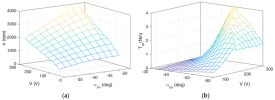
Figure 4.
Dependences of control parameters on (a) speed n (at a constant value of torque of 2.5 Nm) and (b) torque Tm (at a constant speed of 3000 rpm) for a supply angular range of 30 degrees.
3.3. Verification of Simulation Results
The model was adapted for calculations at a given torque value. Significant differences were obtained between drive parameters at similar operating points with different control parameters. This was confirmed by the data shown in Table 2 containing examples of the measured current and efficiency values obtained for two drive operating points. The presented examples show that similar work points can be obtained with many different sets of control parameters. The performed measurements correspond approximately to two operating points of the drive and show how the selection of control parameters (voltage and commutation angles) significantly affects the obtained efficiency values.
Table 2.
Two examples of measurement results of the drive parameters obtained for similar operating points at different values of the control parameters.
The table contains the obtained mean values of the supply current Is av, phase current Iph av, motor efficiency ηm, and drive efficiency ηd for similar operating points and different control parameters: supply voltage V, switch-on angle αon, and switch-off angle αoff.
For the parameter set V = 126 V, αon = −46 degrees, and Δα = 30 degrees in the examples presented, the drive efficiency was approximately 0.78; for the parameter set V = 197 V, αon = −37 degrees, and Δα = 30 degrees, this efficiency was approximately 0.69. Due to these differences, it was necessary to determine the optimal control parameters and to include them in the control process of the drive. For the second operating point, the differences in the efficiency of the drive also reached 10%, for different control parameters.
The presented examples show that, in the case of SRM drives, the regulator should be characterized by a more complex structure than in the case of drives with DC motors.
The correctness of the simulation results was confirmed by performing a series of calculations for various operating points in a wide range of speed, torque, and control parameters for which the measurements were performed. Sample results for different values of the commutation angle and supply voltage are shown in Table 3. On the other hand, Table 4 shows the results of the measurement verification for different values of the load torque and commutation angles at a constant voltage value.
Table 3.
Measurement verifications of calculation results for various values of supply voltage.
Table 4.
Measurement verifications of calculation results for various values of torque.
4. Simulation of the Regulator
4.1. The Proposed Regulator Structure
The drive with proposed voltage and commutation angle regulators, taking their dependence on speed and torque into account, is shown in Figure 5.
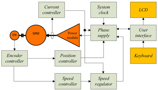
Figure 5.
Structure of the system with the proposed regulator.
The drive has a typical structure and differs from the others by the speed regulator, which takes into account two regulation ranges: voltage regulation range and switch-on angle regulation range.
The structure of the proposed regulator is based on previously calculated optimal dependences of control parameters on speed and torque, which were calculated in the simulation program. This regulator was characterized by a complex structure. The input signals of the controller comprised a speed signal from the encoder module and a torque signal determined indirectly based on measurements of the supply current value.
In the design of the regulator, two methods of speed regulation were considered. The control method changed depending on the results of a comparison of the rotational speed with the value of the switching function. This function determines the relationship between the speed and the torque value for 95% of the nominal voltage value. The basic adjustment range included the low-speed range. Within this range, the adjustable parameter was the supply voltage. The angle values were adjusted to the instantaneous speed and torque values, according to the calculated relationships. This range of regulation ended when a voltage near the rated voltage is reached. The speed of SRM drives could be further increased at constant voltage value by changing the switch-on angle. In this range, the value of the switch-off angle was still adjusted to the current speed and torque value by adding an optimal supply range value from the table to the switch-on angle. The output signals from the regulator comprised the PWM supply voltage, switch-on angle, and switch-off angle. The proposed structure of the regulator is shown in Figure 6.
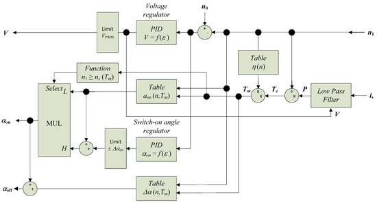
Figure 6.
Structure of the proposed regulator for SRM drive.
The regulator required a torque signal for operation. In the absence of a torque sensor, the measurement signal of the supply current could be used at a constant supply voltage. However, due to its pulsating character, it required pre-filtering. For this purpose, a digital filter which averages the current value over the period of its pulsation (over a given range of the rotational angle) was used. Then, based on the average value of the supply current and the instantaneous speed value, the electromagnetic torque value was calculated. The motor torque was then determined based on this value and the efficiency characteristics as a function of speed (module Table η (n) on Figure 6). For these calculations, the approximate dependence determined for the rated torque value using (10) was used.
The speed signal was sent to the regulator from the optical incremental encoder through a module implemented in the FPGA device. Signals prepared in this way were fed to the regulator module input. The regulator contained two PID modules and two modules, enabling non-linear determination of the optimal values of the switch-on and angular supply range angles. These parameters corresponded to the maximum drive efficiency and minimum value of phase current at different speeds. As a criterion for evaluation, the function was assumed (10).
Based on previous calculations, the optimal values of commutation angles were determined as a function of the values of supply voltage V, rotational speed n, and torque Tm. Each set of these parameters corresponded to a specific rotational speed value. Figure 7 shows the determined dependences of a switch-on angle αon and phase supply angular range Δα vs. rotational speed n and torque Tm.
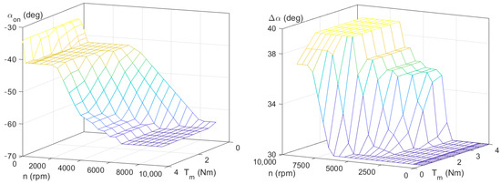
Figure 7.
Dependence of the switch-on angle αon on rotational speed n and torque Tm, and the phase supply angular range Δα on rotational speed n and torque Tm.
4.2. Model Implementation and Simulation Results
The simulation model of the regulator was developed in the MATLAB Simulink program, then implemented in the SRM drive simulation model shown in Figure 3. The dependences of commutation angles on speed and torque as well as the dependence of averaged efficiency on speed were implemented in the form of tables. The intermediate values in the tables were calculated using first-degree spline functions. The switch (module Function n1 ≥ ns (Tm) on Figure 6), which changes mode of the regulator of switch-on angle, between interpolated values from the table and the calculated value in the PID regulator, was realized in the form of a linear function. The developed model of the regulator is shown in Figure 8.
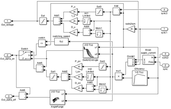
Figure 8.
The regulator model in MATLAB Simulink software.
Using the simulation model, calculations of the drive mechanical characteristics with a typical voltage regulator as well as the proposed voltage and switch-on angle regulator were performed. Table 5 present simulation results obtained for the rated data and those declared by the motor manufacturer.
Table 5.
Motor rated data and results of simulations of the drives with a typical voltage regulator and the proposed voltage and switch-on angle regulator.
For a typical power supply system with a voltage regulator, the results were consistent with those declared by the manufacturer. For the system with the proposed voltage and switch-on angle regulator, the speed control range was wider by 58% at the rated torque value, and the drive power increased to 1190 W.
The disadvantage of this solution is the increase in the phase current RMS value in the regulation commutation angles mode, resulting in an increase in winding losses. At the beginning of this range, the increasing phase current value is small, and grows with the speed. In motors adapted to simultaneously supply the two phases, this is not a limitation. In motors adapted to sequential phases supply, limiting the operating time in this mode may be required.
5. Implementation and Tests of the Regulator in the FPGA Device
5.1. Implementation of the Regulator
The controller was made on the basis of the FPGA device [43] of the Virtex series. In the FPGA device, the dependences of the switch-on angle and phase supply angular range on rotational speed for different torque values were implemented, using the first-degree spline function. These functions were determined for all values of torque in the calculation grid.
Based on these functions, values of commutation angles were determined for instantaneous rotational speed values for the adjacent torque values in the table.
Then, the coefficients of the linear functions, depending on the motor torque passing through these points, were determined. The coefficients a and b of Equations (11) and (12) were calculated.
Then, the values of these functions were calculated for the current torque value. Next, the coefficients of the linear functions passing through these points were determined. From these functions, the values of the optimal switch-on angle and the supply angular range were calculated for the instantaneous value of the rotor position angle and torque. The method of determining the instantaneous values of the commutation angles on the basis of the data from the tables is shown in Figure 9.
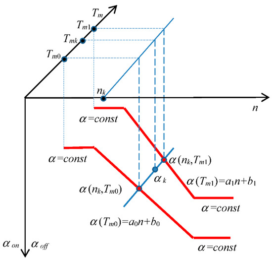
Figure 9.
Method of calculation of the values of commutation angles in the field programmable gate array (FPGA) device.
These relationships are implemented in FPGA in the form of spline functions. In the FPGA controller, these functions have been converted to signed integer types.
In the low-speed range, the values of the switch-on and switch-off angles were determined from the tables based on speed and torque values. After reaching the rated value, the voltage remained constant. Instead of the matrix signal, the signal from the PID controller output was redirected to the switch-on angle output of the control system. An additional increase in speed was obtained by increasing the advance value of the switch-on angle. During this time, the value of the switch-off angle αoff was still determined based on the value of the phase angular supply range Δα table, depending on speed and torque.
As a control unit, a prototype module with an FPGA Xilinx programmable device was used. Signal transmission between the power module and the control unit was implemented via current loops. A block diagram of the controller implemented in the FPGA device is shown in Figure 10.
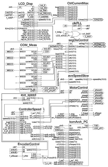
Figure 10.
Schematic diagram of the control system implemented in the FPGA device.
The LCD_Disp module acts as the user interface. It enables setting control parameters and their display on the LCD. The segDisControl module supports an LED display. This module displays current operating parameters such as currents or speeds. An additional module of the user interface is a serial interface komArch_PC. Modules COM_Meas and CtrCurrentMax perform current measurement and current limitation, respectively. The EncoderControl module detects the angular position of the rotor. The ave_speed and aveSpeedSlow modules measure the speed. The ControllerSpeed module contains the proposed regulator, and the MotorControl controls the sequence of supply of the motor phases.
This control system, in open-loop version, consisted of a user interface equipped with a typical four-button keyboard with a serial menu and a two-line LCD alphanumeric display. The current version of the user menu was extended with the speed setting function.
In the open-loop version of the system it worked in an open loop, and switch-on and switch-off angles values were set from the user interface. This module also received a signal from the PWM voltage regulator. This signal switched output transistors at angular intervals resulting from the control algorithm as well as signals from the phase current limitation system. In this system and in the power circuit, 12-bit current sensors with an serial peripheral interface (SPI) interface were used. The measurement results were sent from the sensors to the controller at a speed of up to 80 kilosamples.
For detection of the rotor angular position, an incremental encoder operating at 360 pulses per revolution was used. In the FPGA, the resolution was increased four-fold, using the decoding of all signal edges in both encoder channels.
The signal delays in the FPGA encoder module were approximately 15 ns. However, due to the signal transmission systems between the FPGA and peripheral modules, the total delays introduced in the control system from the appearance of a signal slope from the encoder to the setting of the appropriate configuration of signals controlling the output transistors were about 0.7 µs.
The FPGA controller structure was expanded to include a regulator module. This module comprised three parallel operating modules, including one with a multiplexer, used to switch on the PID regulator of the switch-on angle upon reaching the value of the rated voltage. A schematic of this module is shown in Figure 11.
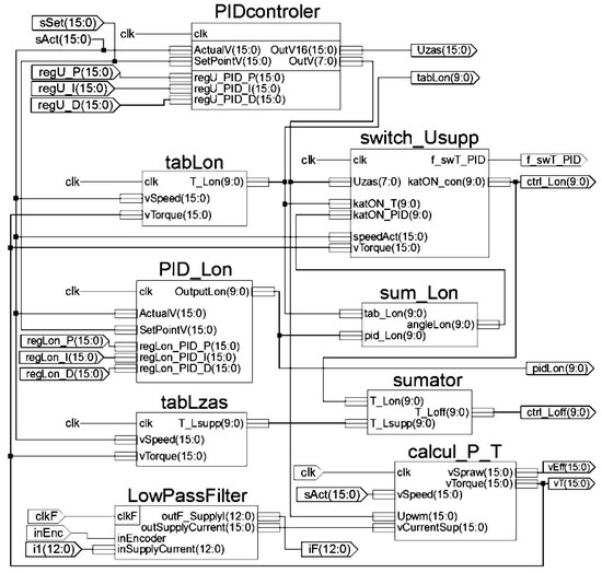
Figure 11.
Block diagram of the proposed regulator implemented in the FPGA device.
According to the schematic of the regulator shown in Figure 6, the modules presented in Figure 11 perform the following functions:
- -
- PIDcontroler—the PID voltage regulator;
- -
- tabLon—the table of switch-on angle values;
- -
- tabLzas—the table of supply angular range values;
- -
- PID_Lon—the PID switch-on angle regulator;
- -
- LowPassFilter—the low pass filter for calculations of current average value, synchronized with phase supply cycle;
- -
- switch_Usupp—the module for switch-on angle regulation range determination;
- -
- sumLon—the module for switch-on angle value determination from the PID regulator;
- -
- sumator—the module for determination of the switch-off angle values;
- -
- calcul_P_T—the module for torque value calculations based on average current values.
The modules implemented in the FPGA device, shown on the scheme in Figure 11, corresponded to the modules in the block diagram of the regulator presented in Figure 6. Module PIDcontroller corresponds to the voltage regulator and module PID_Lon corresponds to the switch-on angle regulator. The tabLon and tabLzas include tabular dependences of switch-on angle and phase supply angular range values, and corresponding to Table αon (n, Tm) and Table Δα (n, Tm) modules shown in Figure 6, respectively.
The LowPassFilter and calcul_P_T modules marked in Figure 6 as Low Pass Filter and Table η (n) are used to determine the value of torque. They contain a low-pass filter of the supply current and the dependence of efficiency vs. speed.
The functions of mode switch module Function n1 ≥ ns (Tm) and multiplexer MUL module in the schematic in Figure 6 fulfill the FPGA switch_Usupp module. On the output of this module, the value of the switch-on angle direct from the array of tabLon or through the sum_Lon module which adds the value from the PID_Lon regulator is set.
The sumator module calculates the value of the switch-off angle, based on the current switch-on angle value αon downloaded from the switch_Usupp module output and the value of the phase supply angular range Δα, from the table contained in the tabLzas module.
The values of the gain coefficients of the PID controllers were determined in the simulation program for voltage and switch-on angle regulators.
5.2. Tests of the Regulator
The correctness of the regulator implementation was tested by comparing the values of commutation angles and torque determined in the FPGA system with the values obtained from the simulation. The range of switch-on angle values at the output of the PID controller was limited to two degrees (Figure 8, module Sat1); therefore, the maximum difference of the switch-on angle value at the controller output in relation to the data stored in the table did not exceed this value.
In order to visualize these dependences of control parameters on speed and torque value, a USB module was implemented in the FPGA system, thanks to which speed waveforms and the corresponding changes in control parameters were recorded in the computer.
Measurements were made at constant speed value by changing the load torque and at constant load torque by changing the rotational speed. The calculations in the simulation model were carried out for the operating states in which the measurements were made. The torque values calculated in the FPGA system on the basis of the measured supply current values were compared with the simulation results in the MATLAB Simulink program. In the course of the measurements, the relationships of the commutation angles to changes in the value of the load torque and rotational speed were recorded. Figure 12 and Figure 13 present a comparison of the obtained waveforms. The blue waveforms show the simulation results obtained in MATLAB Simulink, while the red waveforms were calculated in the FPGA system and archived in a text file on the computer via a USB port. The first example (Figure 12) shows the changes in control parameters in accordance with the adopted optimization criterion during changes in the load torque at constant speed.
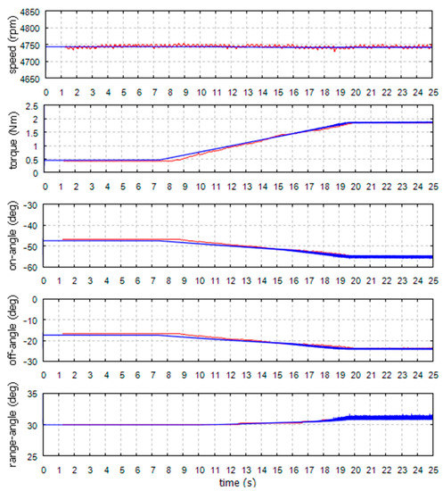
Figure 12.
Load torque waveforms and corresponding values of commutation angles with load changes at constant rotational speed.
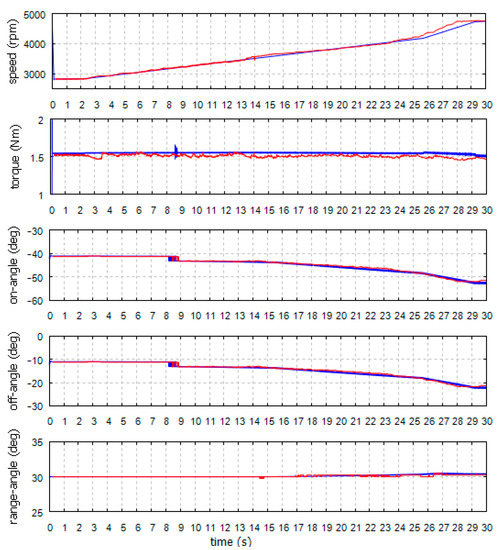
Figure 13.
Speed waveforms and corresponding values of commutation angles at constant load torque.
The first graph shows the speed waveforms obtained from the simulation and measured in the FPGA system, based on the signals from the incremental encoder. The second shows the waveform of torque obtained from the simulation in MATLAB Simulink and calculated in the FPGA system, based on the value of the measured supply current. The next charts show the values of the commutation angles: the switch-on angle, the switch-off angle, and the phase supply angular range, obtained from the simulation and calculated in the FPGA controller, for the presented speed and torque waveforms.
The example presented in Figure 13 shows the reaction of the system to changes in the set speed value at a constant load torque. The first diagram shows the speed waveforms measured in the FPGA system and similar conditions set in the simulation program. The second diagram shows the torque waveforms obtained from the simulation in MATLAB Simulink and calculated in the FPGA system based on measurement values of the supply current. The following diagrams show the corresponding values in the commutation angles: switch-on angle, switch-off angle, and phase supply angular range, obtained from the simulation and calculated in the FPGA system.
The measurements results are shown in Figure 12, which were made at a speed higher than the maximum speed obtained in a drive with a typical voltage regulator. On the other hand, in Figure 13, at a speed about 3200 rpm (t = 9.6 s), the angle regulator was switched on. The speed of 3200 rpm is the maximum speed with a load torque of 1.5 Nm that can be achieved in a drive with a typical voltage regulator.
Table 6 summarizes the results obtained from simulation, in the FPGA device and stored in the tables, for various operating points:
Table 6.
Comparison of tabulated values, simulation and calculations results in an FPGA device.
- -
- For the voltage regulator operating range;
- -
- For the voltage regulator operating range directly before switching on the switch-on angle regulator;
- -
- For the switch-on angle regulator operating range directly after switching;
- -
- For the switch-on angle regulator operating range at the rated voltage.
The table summarizes the values of speed, torque, and commutation angles, as well as differences between the values obtained in FPGA ΔFPGA-tab and from the simulation Δsym-tab, and those determined from the tables. The last column contains the error values δFPGA-sym determined for the regulator implemented in FPGA in comparison to the simulation results.
6. Conclusions
The implementation of optimal dependences of commutation angles on voltage, speed, and torque values enabled the system to operate at a high level of efficiency. The structure of the presented regulator enables the use of the full speed range and selection of optimal values of control parameters. The use of an averaging filter for the repetition period of supply current prevents changes in the values of commutation angles during the phase supply cycle.
The use of the FPGA device to implement the controller enabled experimental tests to be performed over a wide speed range without introducing significant delays in the control process. During changes in load torque within the lower speed range, the supply voltage was regulated by the PID regulator; the angle values changed based on tabular dependences in order to maintain a high level of efficiency. In the high-speed range, the phase supply voltage remained constant, whereas the phase supply angles were corrected by the angle-on PID regulator. In order to obtain optimal working conditions, the switch-off angle value was corrected based, in both cases, on tabular dependences.
The switching function worked properly, causing only slight voltage fluctuations when the regulator operating modes were changed. The close convergence of the measurement and simulation results enabled further testing of the drive operation in the simulation program.
Implantation of the optimal dependence of the commutation angles on the supply voltage, speed, and torque in the control system enabled the drive to operate at a high level of efficiency. Calculated efficiency values were obtained after reaching a steady state. In dynamic states, these values will be close to the established results, provided that the changes are slow. During rapid changes in speed or load torque, additional energy is drawn or returned to the power source, depending on the type of these changes, due to the rotor moment of inertia. However, after reaching a steady state, the system will return to the determined characteristics. In typical SRM drives, speed regulation is limited to the range achieved with voltage regulation. At the same time, within this range, values of commutation angles are changed according to a predetermined relationship or by an additional controller. Very often, the adjustment of commutation angles is limited to the adjustment of the switch-on angle, at a constant value of the angular supply range.
The structure of the presented regulator enables the use of the full range of speed regulation with the simultaneous selection of the values of the control parameters.
The regulation range was extended by the adjustment of commutation angles at the rated value of the supply voltage. This adjustment allows the nominal torque value to be maintained. As a result, an expansion of the drive operation range (while maintaining a rated torque by 58% compared to drives using only voltage regulation) was obtained.
For the operation of the regulator, it is necessary to know the value of load torque, determined indirectly on the basis of the average value of the supply current. Current measurement results are averaged over the period of the phase supply cycle, which prevents changes in the values of the commutation angles during phase supply. In order to determine the torque more accurately within the low-speed range, the system additionally accounts for the approximate dependence of the motor’s efficiency on the rotational speed.
To implement the controller, an FPGA device was used. This enabled the system operation to be tested over a wide range of speeds without introducing significant delays in the control process, and to use the controller for high-speed SRM drives.
In this project, an FPGA device was used to minimize control delay during drive tests and to limit errors in high-speed range. This regulator can also be implemented in microprocessors.
In terms of costs and system solutions, the drive does not differ significantly from typical solutions. Such a system should include sensors of the angular position of the rotor and the supply current. The main difference between this drive system and typical solutions is the change of the implemented control algorithm.
During the speed reference or load torque changes, the PID voltage regulator is used within the lower speed range and the angle values are changed based on tabular relationships in order to maintain a high level of efficiency. In the high-speed range, the phase supply voltage remains constant, while the PID switch-on angle regulator is used and the width of the phase supply range is changed based on tabular relationships. The angle regulator is activated according to the adopted switching function.
The mode switch worked properly, causing voltage fluctuations of only a few percentage points, when switching the regulator operating modes. Close convergence of the simulation results with the experimental tests was obtained.
The results of the simulations demonstrate the correct operation of the regulator. The values of the angles after reaching steady states were consistent with the predetermined results. Moreover, the values of the angles during the experimental tests from the regulator circuit implemented in the FPGA were consistent with the values determined in the simulation process, indicating the correct implementation of the regulator.
The next stage of this research will involve long-term tests of the drive with the developed regulator in a small electric vehicle. These tests will include measurements of the drive parameters at operation in dynamic states and adjustments of the regulator settings. The influence of using the regulator on thermal conditions of the motor operating in the extended speed range, with power greater than that rated, will also be examined.
Author Contributions
Conceptualization, K.T., and K.W.; methodology, K.T., K.W. and D.R.; software, K.T., K.W. and D.R.; investigation, D.R.; writing—original draft preparation, K.T., K.W. and D.R.; writing—review and editing, G.T.; visualization, K.T., K.W. and D.R. All authors have read and agreed to the published version of the manuscript.
Funding
This research received no external funding.
Institutional Review Board Statement
Not applicable.
Informed Consent Statement
Not applicable.
Data Availability Statement
Not applicable.
Conflicts of Interest
The authors declare no conflict of interest.
References
- Yildirim, M.; Polat, M.; Kürüm, H. A survey on comparison of electric motor types and drives used for electric vehicles. In Proceedings of the 16th International Power Electronics and Motion Control Conference and Exposition, Antalya, Turkey, 21–24 September 2014; pp. 218–223. [Google Scholar]
- Nugraha, Y.U.; Asfani, A.D.; Riawan, D.C.; Nur Yuniarto, M. Performance Improvement of Axial Switched Reluctance Motor using Low-Cost Magnet. In Proceedings of the 6th International Conference on Electric Vehicular Technology, Bali, Indonesia, 18–21 November 2019; pp. 300–303. [Google Scholar]
- Pindoriya, R.M.; Rajpurohit, B.S.; Kumar, R.; Srivastava, K.N. Comparative analysis of permanent magnet motors and switched reluctance motors capabilities for electric and hybrid electric vehicles. In Proceedings of the IEEMA Engineer Infinite Conference, New Delhi, India, 13–14 March 2018; pp. 1–5. [Google Scholar]
- Hu, Y.; Gan, C.; Sun, Q.; Li, P.; Wu, J.; Wen, H. Modular Tri-Port High-Power Converter for SRM Based Plug-in Hybrid Electrical Trucks. IEEE Trans. Power Electron. 2018, 33, 3247–3257. [Google Scholar] [CrossRef]
- Zhao, E.; Song, S.; Ma, Z.; Zhang, X.; Ning, L.; Liu, Y. Design and initial testing of an integrated switched reluctance starter/generator system for unmanned aerial vehicle. CES Trans. Electron. Mach. Syst. 2018, 2, 377–383. [Google Scholar] [CrossRef]
- Ralev, I.; Qi, F.; Burkhart, B.; Klein-Hessling, A.; De Doncker, R.W. Impact of Smooth Torque Control on the Efficiency of a High-Speed Automotive Switched Reluctance Drive. IEEE Trans. Ind. Appl. 2017, 53, 5509–5517. [Google Scholar] [CrossRef]
- Husain, T.; Elrayyah, A.; Sozer, Y.; Husain, I. Unified Control for Switched Reluctance Motors for Wide Speed Operation. IEEE Trans. Ind. Electron. 2019, 66, 3401–3411. [Google Scholar] [CrossRef]
- Chen, H.; Chen, M.; Su, W. Voltage-Doubler Front-End Converter for Two-Quadrant Switched Reluctance Motor Drives. In Proceedings of the IEEE Applied Power Electronics Conference and Exposition, Phoenix, AZ, USA, 9–12 June 2019; pp. 271–276. [Google Scholar]
- Akash, C.B.; Ashok, S.; Sandeep, J. FPGA based speed controller for 8/6 switched reluctance motor using hysteresis controller. In Proceedings of the 2nd International Conference on Intelligent Computing, Instrumentation and Control Technologies, Kerala, India, 5–6 July 2019; pp. 962–966. [Google Scholar]
- Rataj, D.; Slawik, D.; Wrobel, K.; Tomczewski, K. A fast switched reluctance motor controller based on FPGA. ITM Web Conf. 2018, 19, 01028. [Google Scholar] [CrossRef][Green Version]
- Reddy, B.P.; Janaki, R.V.; Kumar, K.S. Torque ripple minimization of SRM using sense coils and FPGA. In Proceedings of the IEEE International Conference on Power Electronics—Smart Grid and Renewable Energy, Kerala, India, 2–4 January 2020; pp. 1–6. [Google Scholar]
- Gan, C.; Wu, J.; Sun, Q.; Kong, W.; Li, H.; Hu, Y. A Review on Machine Topologies and Control Techniques for Low-Noise Switched Reluctance Motors in Electric Vehicle Applications. IEEE Access 2018, 6, 31430–31443. [Google Scholar] [CrossRef]
- Castro, J.; Andrada, P.; Blanque, B. Minimization of torque ripple in switched reluctance motor drives using an enhanced direct instantaneous torque control. In Proceedings of the XXth International Conference on Electrical Machines, Marseille, France, 2–5 September 2012; pp. 1021–1026. [Google Scholar]
- Cui, X.; Sun, J.; Gan, C.; Gu, C.; Zhang, Z. Optimal Design of Saturated Switched Reluctance Machine for Low Speed Electric Vehicles by Subset Quasi-Orthogonal Algorithm. IEEE Access 2019, 7, 101086–101095. [Google Scholar] [CrossRef]
- Mynarek, P.; Gabor, R.; Kowol, M.; Kolodziej, J.; Lukaniszyn, M. Analysis of a Modified-Structure Switched Reluctance Motor Designed for an E-Bike. Przeglad Elektrotechniczny 2019, 5, 133–136. [Google Scholar] [CrossRef]
- Deng, X.; Mecrow, B.; Wu, H.; Martin, R. Design and Development of Low Torque Ripple Variable-Speed Drive System with Six-Phase Switched Reluctance Motors. IEEE Trans. Energy Convers. 2018, 33, 420–429. [Google Scholar] [CrossRef]
- Wang, M. Direct Torque Controlled System Based on PI Regulator for Switched Reluctance Motor Drive. In Proceedings of the IEEE International Conference on Control and Automation, Guangzhou, China, 30 May–1 June 2007; pp. 606–610. [Google Scholar]
- Cheng, H.; Chen, H.; Yang, Z. Average torque control of switched reluctance machine drives for electric vehicles. IET Electron. Power Appl. 2015, 9, 459–468. [Google Scholar] [CrossRef]
- Toudji, R.; Zeroug, H.; Sahraoui, H.; Mahmoudi, O. Performance evaluation into the fault-tolerant operation of SRM with proportional-Integral and integral-proportional speed controllers. In Proceedings of the 8th IET International Conference on Power Electronics—Machines and Drives, Glasgow, UK, 19–21 April 2016; pp. 1–7. [Google Scholar]
- Su, Z.; Zhang, C.; Wang, M.; Dai, Z. Research on switched reluctance motor speed control system based on robust control. In Proceedings of the 43rd Annual Conference of the IEEE Industrial Electronics Society, Beijing, China, 29 October–1 November 2017; pp. 6229–6232. [Google Scholar]
- Da Cunha Reis, M.R.; de Araujo, W.R.H.; Gomes, V.M.; dos Santos e Silva, F.; Ganzaroli, C.A.; Gomes, F.A.; Wainer, G.A.; Calixto, W.P. Optimized techniques for driving and control of the switched reluctance motor to improve efficiency. Control Eng. Pract. 2019, 90, 1–18. [Google Scholar] [CrossRef]
- Wang, Y.; Wu, H.; Zhang, W.; Ma, Y. A high efficiency direct instantaneous torque control of SRM using commutation angles control. In Proceedings of the 17th International Conference on Electrical Machines and Systems, Hangzhou, China, 22–25 October 2014; pp. 2863–2866. [Google Scholar]
- Klein-Hessling, A.; Burkhart, B.; Scharfenstein, D.; De Doncker, R.W. The effect of excitation angles in single-pulse controlled switched reluctance machines on acoustics and efficiency. In Proceedings of the 17th International Conference on Electrical Machines and Systems, Hangzhou, China, 22–25 October 2014; pp. 2661–2666. [Google Scholar]
- Sun, Q.; Wu, J.; Gan, C. Optimized Direct Instantaneous Torque Control for SRMs With Efficiency Improvement. IEEE Trans. Ind. Electron. 2021, 68, 2072–2082. [Google Scholar] [CrossRef]
- Boler, O.; Gundogmus, O.; Sozer, Y. Direct Voltage Controller for SRMs in Achieving Torque Ripple Minimization over Wide Speed Range. In Proceedings of the IEEE Energy Conversion Congress and Exposition, Detroit, MI, USA, 11–15 October 2020; pp. 4674–4680. [Google Scholar]
- Sun, X.; Wu, J.; Lei, G.; Guo, Y.; Zhu, J. Torque Ripple Reduction of SRM Drive Using Improved Direct Torque Control with Sliding Mode Controller and Observer. IEEE Trans. Ind. Electron. 2020, 1–11. [Google Scholar] [CrossRef]
- Babitha, S.; Kulkarni, V.; Koujalagi, J.P. Vector Control Based Speed and Flux estimation in Switched Reluctance Motor Using ANN Controller. In Proceedings of the 4th International Conference on Recent Trends on Electronics, Bangalore, India, 17–18 May 2019; pp. 10–14. [Google Scholar]
- Cheng, H.; Wang, L.; Xu, L.; Ge, X.; Yang, S. An Integrated Electrified Powertrain Topology with SRG and SRM for Plug-In Hybrid Electrical Vehicle. IEEE Trans. Ind. Electron. 2020, 67, 8231–8241. [Google Scholar] [CrossRef]
- Mehta, S.; Husain, I.; Pramod, P. Predictive Current Control of Mutually Coupled Switched Reluctance Motors Using Net Flux Method. In Proceedings of the IEEE Energy Conversion Congress and Exposition, Baltimore, MD, USA, 29 September–3 October 2019; pp. 4918–4922. [Google Scholar]
- Mademlis, C.; Kioskeridis, I. Gain-Scheduling Regulator for High-Performance Position Control of Switched Reluctance Motor Drives. IEEE Trans. Ind. Electron. 2010, 57, 2922–2931. [Google Scholar] [CrossRef]
- Chiba, A.; Kiyota, K.; Hoshi, N.; Takemoto, M.; Ogasawara, S. Development of a Rare-Earth-Free SR Motor with High Torque Density for Hybrid Vehicles. IEEE Trans. Energy Convers. 2015, 30, 175–182. [Google Scholar] [CrossRef]
- Hadke, V.V.; Thakre, M.P. Integrated Multilevel Converter Topology for Speed Control of SRM Drive in Plug in-Hybrid Electric Vehicle. In Proceedings of the 3rd International Conference on Trends in Electronics and Informatics, Tirunelveli, India, 23–25 April 2019; pp. 1013–1018. [Google Scholar]
- Sun, Q.; Wu, J.; Gan, C.; Si, J.; Guo, J.; Hu, Y. Cascaded Multiport Converter for SRM-Based Hybrid Electrical Vehicle Applications. IEEE Trans. Power Electron. 2019, 34, 11940–11951. [Google Scholar] [CrossRef]
- Gan, C.; Jin, N.; Sun, Q.; Kong, W.; Hu, Y.; Tolbert, L.M. Multiport Bidirectional SRM Drives for Solar-Assisted Hybrid Electric Bus Powertrain with Flexible Driving and Self-Charging Functions. IEEE Trans. Power Electron. 2018, 33, 8231–8245. [Google Scholar] [CrossRef]
- Xia, Z.; Bauman, J. An Integrated Modular Converter for Switched Reluctance Motor Drives in Range-Extended Electric Vehicles. In Proceedings of the IEEE Transportation Electrification Conference and Expo, Detroit, MI, USA, 19–21 June 2019; pp. 1–7. [Google Scholar]
- Singh, G.; Singh, B. Design and Implementation of Sliding Mode Control of Light Electric Vehicle Employing Switched Reluctance Motor. In Proceedings of the IECON, Lisbon, Portugal, 14–17 October 2019; pp. 2646–2651. [Google Scholar]
- Song, J.; Song, S.; Qu, B. Application of an adaptive PI controller for a switched reluctance motor drive. In Proceedings of the IEEE 2nd Annual Southern Power Electronics Conference, Auckland, New Zealand, 5–8 December 2016; pp. 1–5. [Google Scholar]
- Meisel, J. Principles of Electromechanical Energy Conversion; Krieger Pub Co.: Malabar, FL, USA, 1984. [Google Scholar]
- Du, J.; Long, Y.; Yuan, S.; He, J.; Yang, K.; Li, S. Mathematical Model for a Novel Electromechanical Actuator based on Lagrange-Maxwell Equation. In Proceedings of the IEEE International Electric Machines & Drives Conference, San Diego, CA, USA, 12–15 May 2019; pp. 1929–1936. [Google Scholar]
- Guo, J.; Liu, X.; Li, S. Flux-Weakening Control for Variable Flux Reluctance Machine Excited by Zero-Sequence Current Considering Zero-Sequence Resistive Voltage Drop. IEEE Trans. Energy Convers. 2020, 36, 1–9. [Google Scholar] [CrossRef]
- Moson, I.; Wilk, A. Lagrange’s energy method based approach for switched reluctance drive systems modelling. In Proceedings of the European Conference on Power Electronics and Applications, Aalborg, Denmark, 2–5 September 2007; pp. 1–10. [Google Scholar]
- Nguyen, D.; Bahri, I.; Krebs, G.; Berthelot, E.; Marchand, C.; Ralev, I.; Burkhart, B.; De Doncker, R.W. Efficiency Improvement by the Intermittent Control for Switched Reluctance Machine in Automotive Application. IEEE Trans. Ind. Appl. 2019, 55, 4167–4182. [Google Scholar] [CrossRef]
- Zhang, M.; Bahri, I.; Mininger, X.; Vlad, C.; Xie, H.; Berthelot, E.; Hu, W. Vibration Reduction Controller for a Switched Reluctance Machine based on HW/SW Partitioning. IEEE Trans. Ind. Inform. 2020, 1–11. [Google Scholar] [CrossRef]


Publisher’s Note: MDPI stays neutral with regard to jurisdictional claims in published maps and institutional affiliations. |
© 2021 by the authors. Licensee MDPI, Basel, Switzerland. This article is an open access article distributed under the terms and conditions of the Creative Commons Attribution (CC BY) license (http://creativecommons.org/licenses/by/4.0/).