
A Switched Reluctance Motor Drive Controller Based on an FPGA Device with a Complex PID Regulator


Abstract
:1. Introduction: SRM Control Methods
2. Mathematical Model of the Drive
- -
- The power supply state in which the transistors are switched on when the switch-on angle position is reached:
- -
- The idle loop state, to which the system is switched during the pulse width modulation (PWM) state and in the current limitation mode:
- -
- And the state of energy return to the source, in which the system is switched on when the switch-off angle position is reached:where V is the supply voltage, vT is the source drain transistor voltage, and vD is the diode voltage.
3. Simulation of the Drive
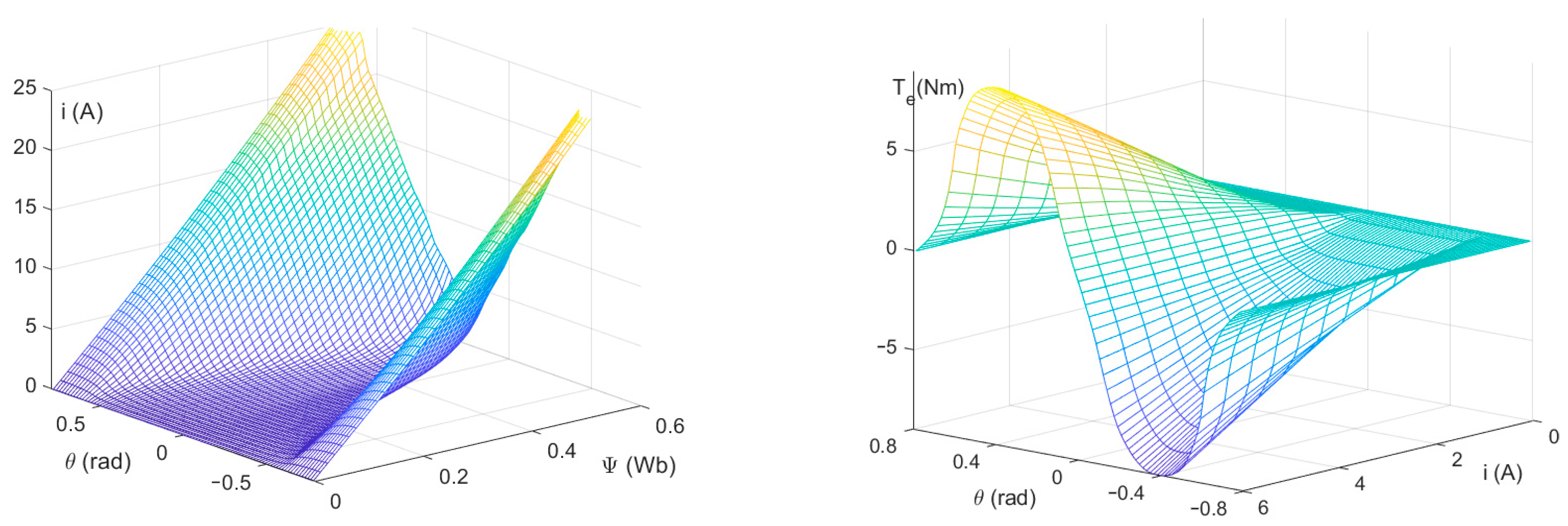
3.1. Determination of Model Parameters
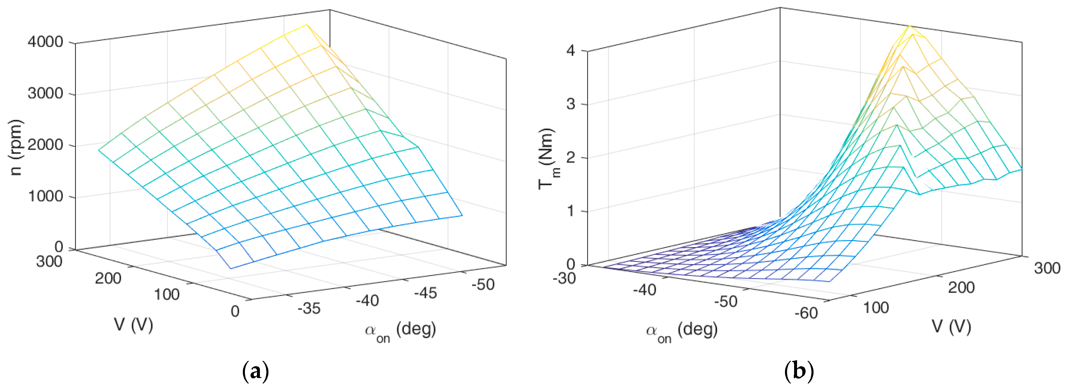
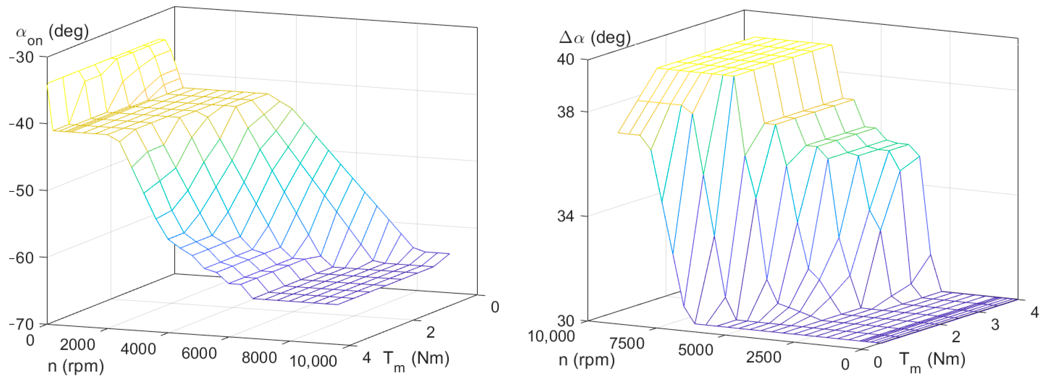
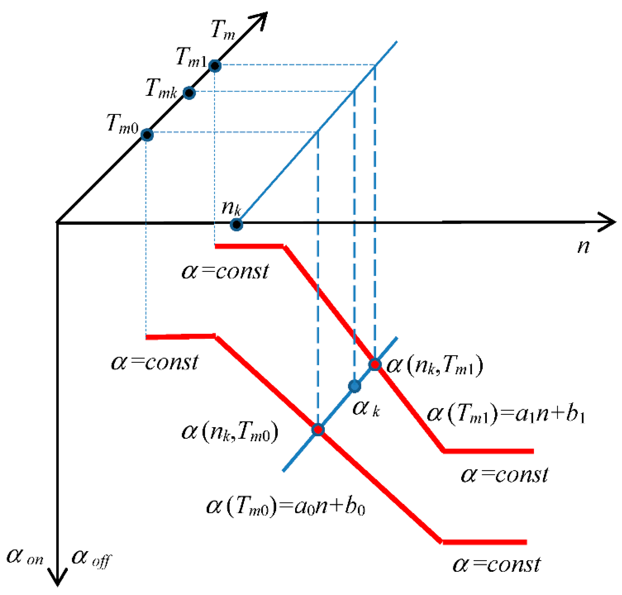
3.2. Determination of Control Characteristics
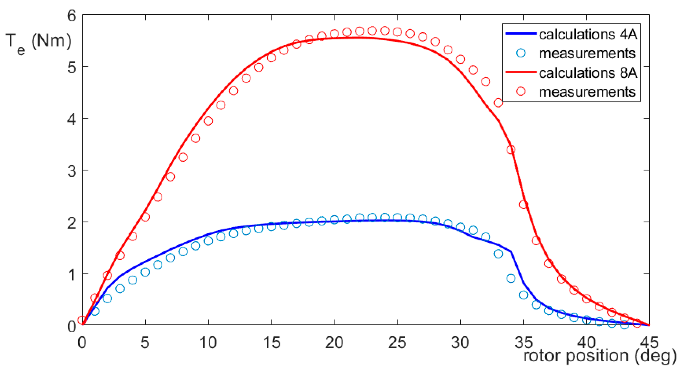
3.3. Verification of Simulation Results
4. Simulation of the Regulator
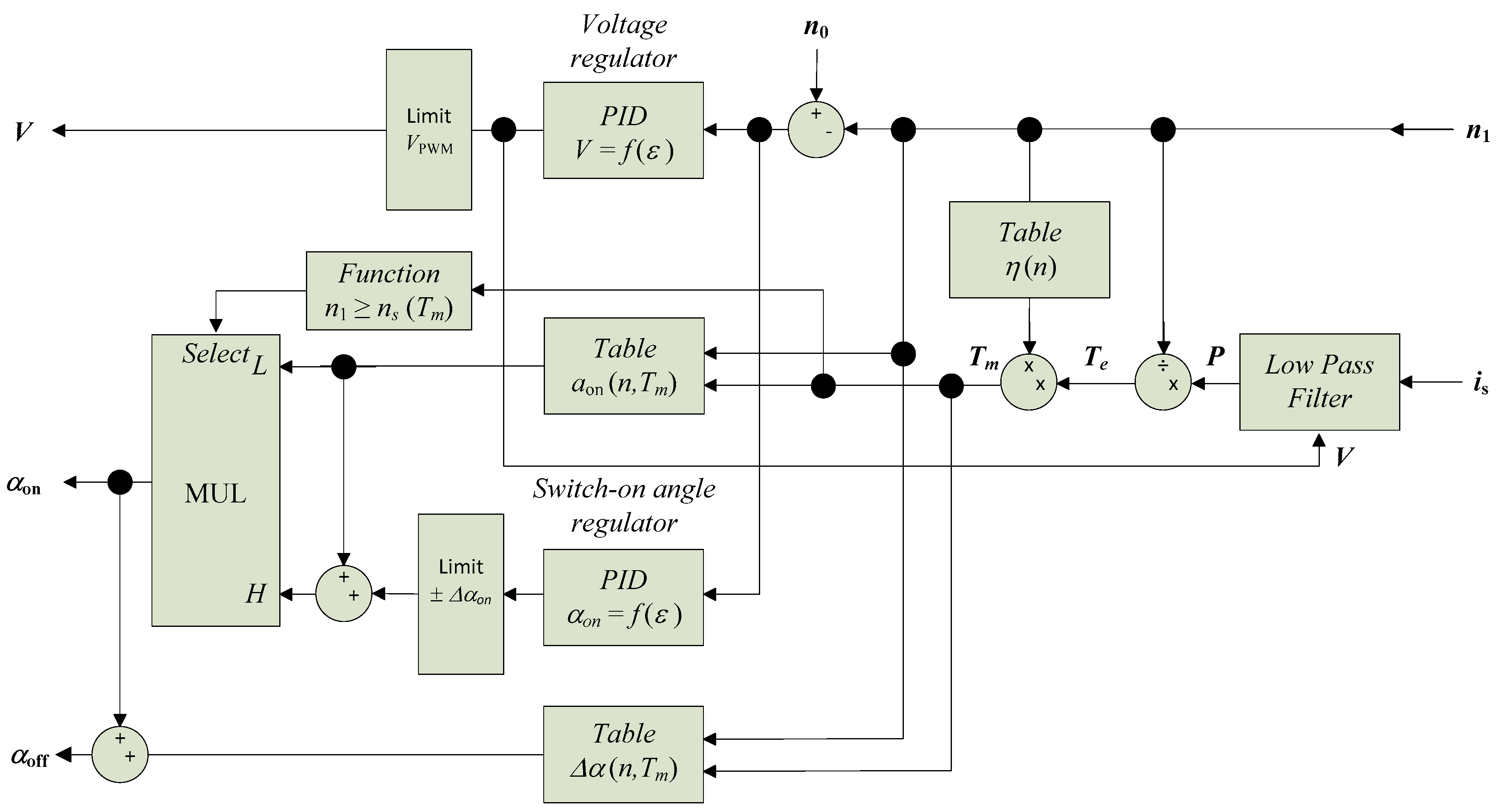
4.1. The Proposed Regulator Structure
4.2. Model Implementation and Simulation Results
5. Implementation and Tests of the Regulator in the FPGA Device
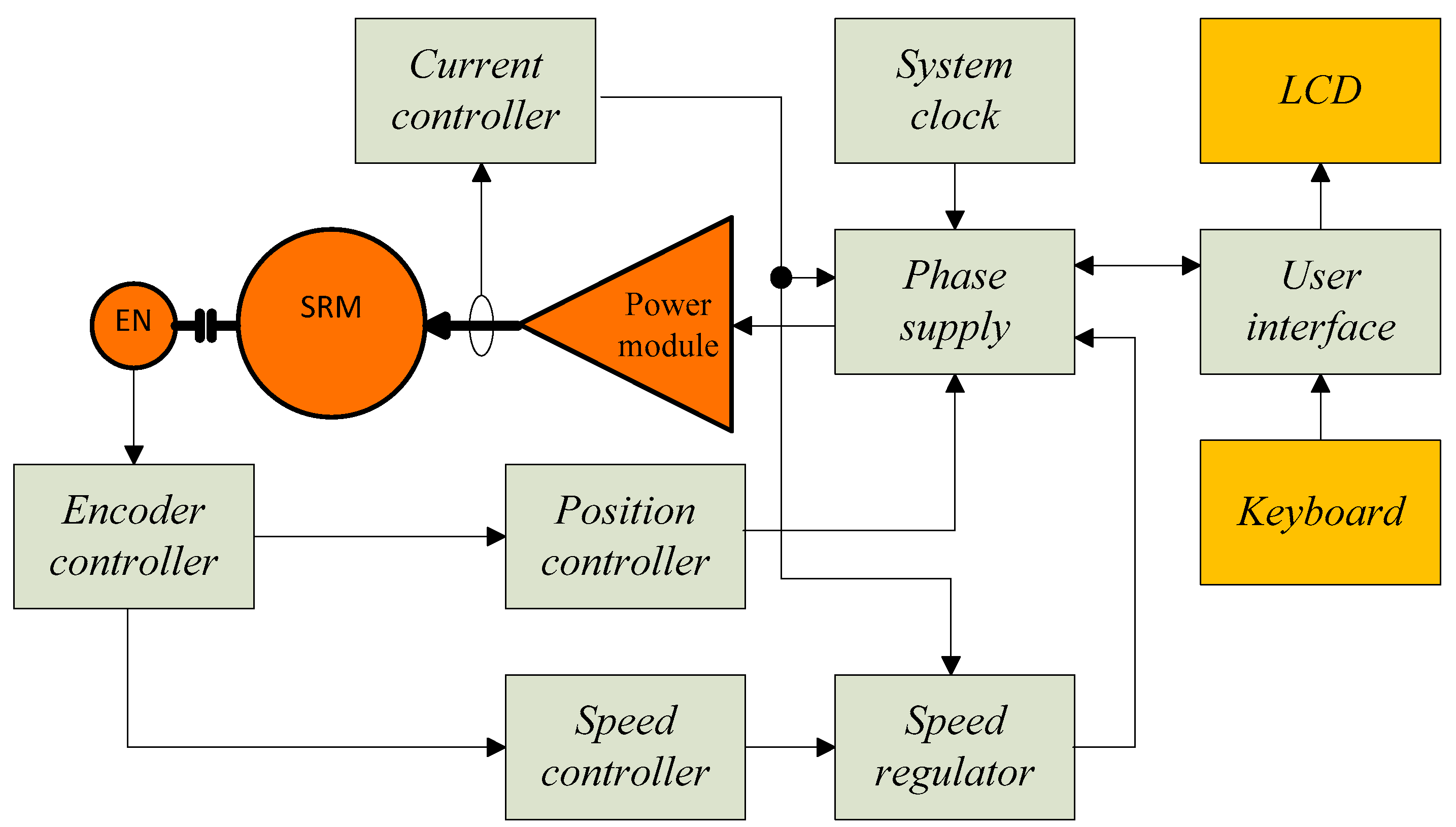
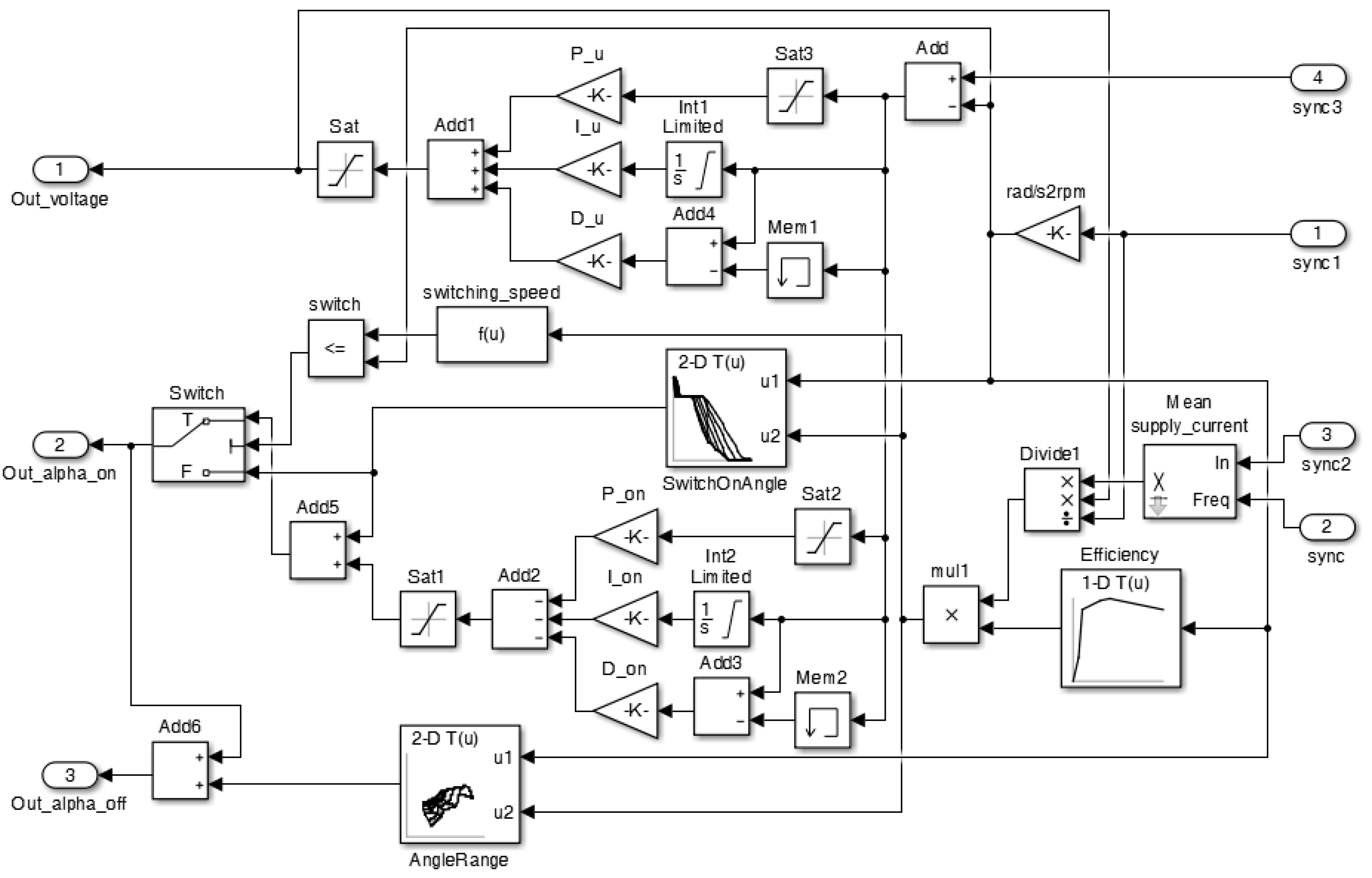
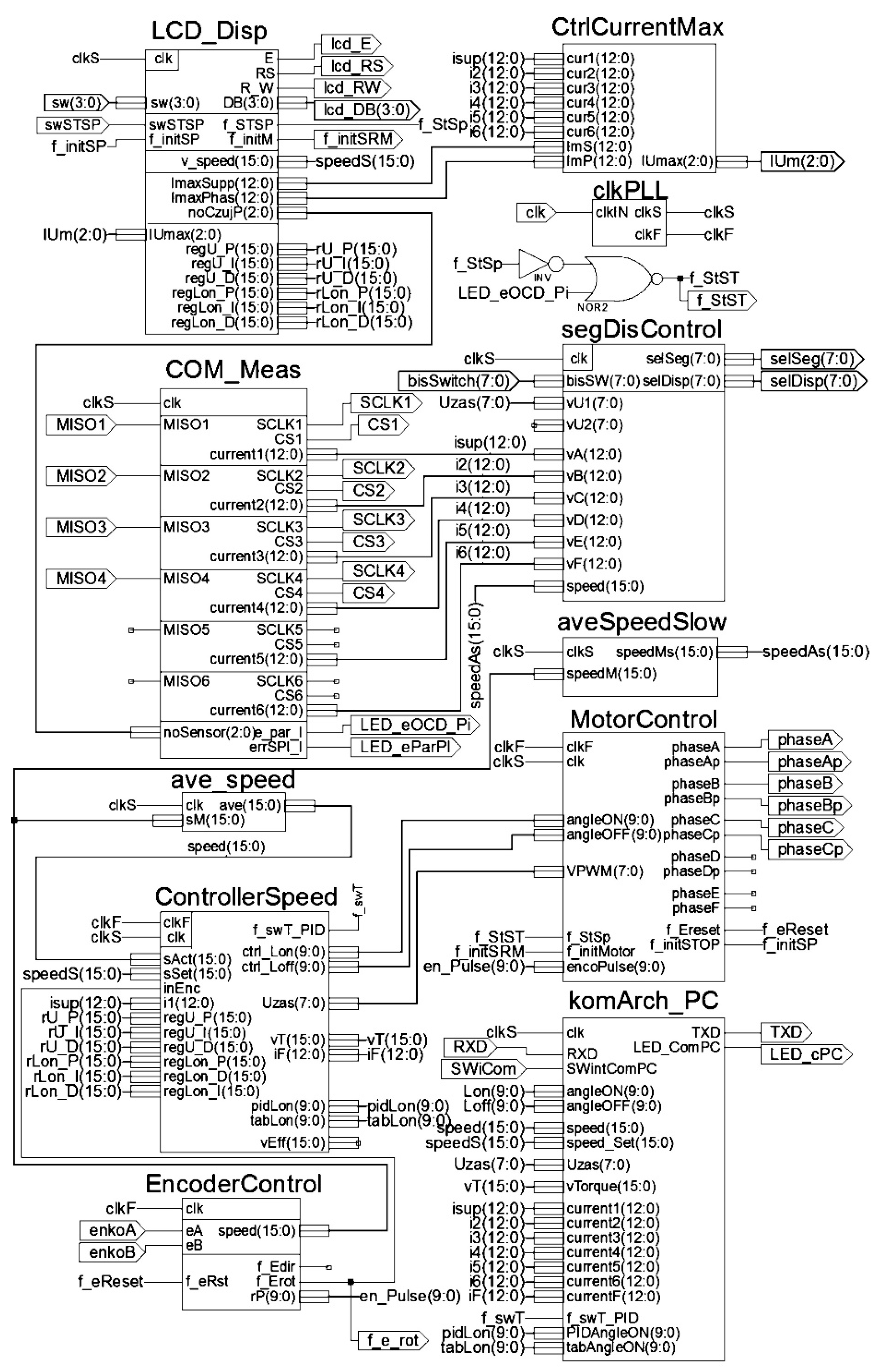
5.1. Implementation of the Regulator
- -
- PIDcontroler—the PID voltage regulator;
- -
- tabLon—the table of switch-on angle values;
- -
- tabLzas—the table of supply angular range values;
- -
- PID_Lon—the PID switch-on angle regulator;
- -
- LowPassFilter—the low pass filter for calculations of current average value, synchronized with phase supply cycle;
- -
- switch_Usupp—the module for switch-on angle regulation range determination;
- -
- sumLon—the module for switch-on angle value determination from the PID regulator;
- -
- sumator—the module for determination of the switch-off angle values;
- -
- calcul_P_T—the module for torque value calculations based on average current values.
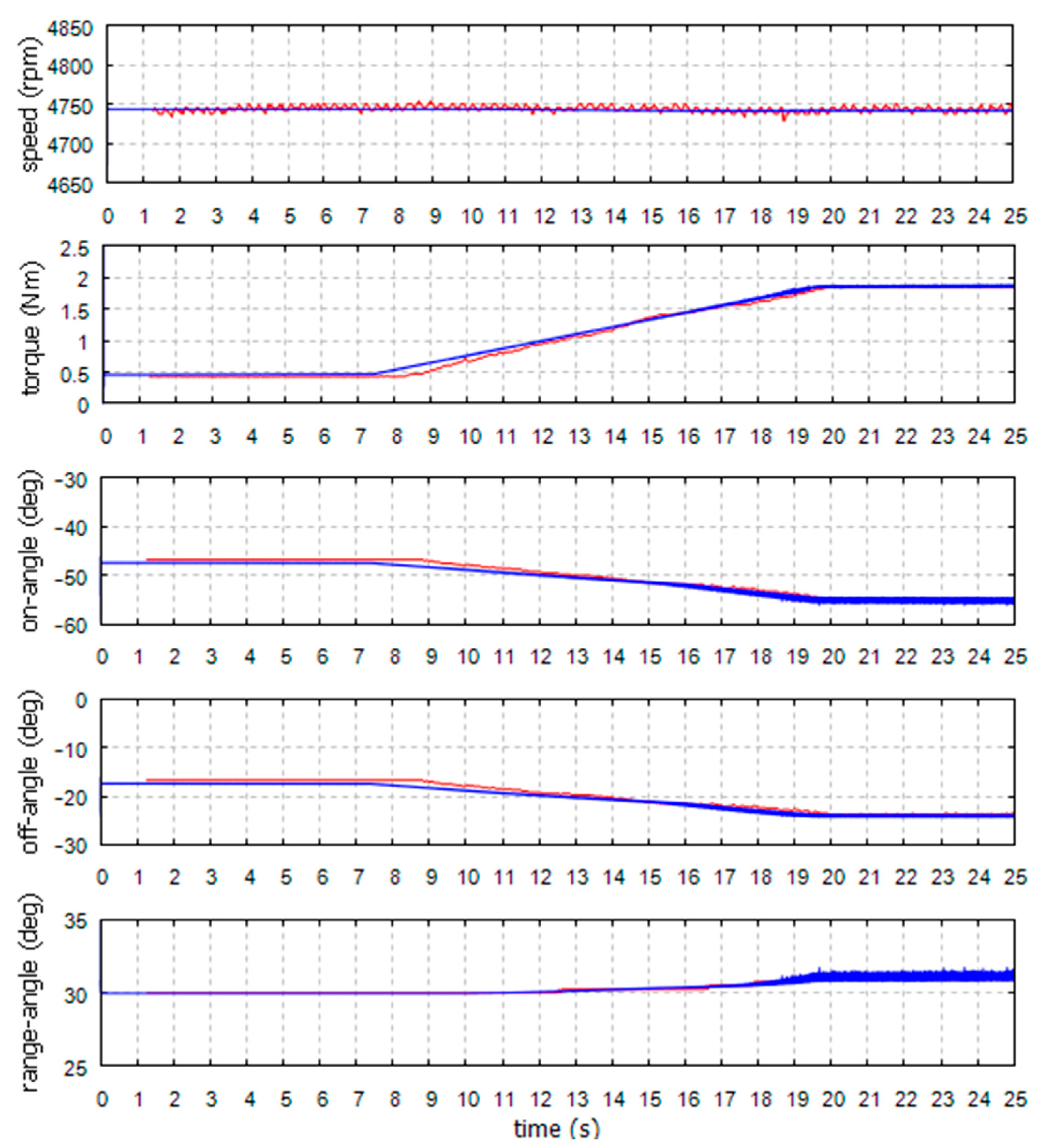
5.2. Tests of the Regulator
- -
- For the voltage regulator operating range;
- -
- For the voltage regulator operating range directly before switching on the switch-on angle regulator;
- -
- For the switch-on angle regulator operating range directly after switching;
- -
- For the switch-on angle regulator operating range at the rated voltage.
6. Conclusions
Author Contributions
Funding
Institutional Review Board Statement
Informed Consent Statement
Data Availability Statement
Conflicts of Interest
References
- Yildirim, M.; Polat, M.; Kürüm, H. A survey on comparison of electric motor types and drives used for electric vehicles. In Proceedings of the 16th International Power Electronics and Motion Control Conference and Exposition, Antalya, Turkey, 21–24 September 2014; pp. 218–223. [Google Scholar]
- Nugraha, Y.U.; Asfani, A.D.; Riawan, D.C.; Nur Yuniarto, M. Performance Improvement of Axial Switched Reluctance Motor using Low-Cost Magnet. In Proceedings of the 6th International Conference on Electric Vehicular Technology, Bali, Indonesia, 18–21 November 2019; pp. 300–303. [Google Scholar]
- Pindoriya, R.M.; Rajpurohit, B.S.; Kumar, R.; Srivastava, K.N. Comparative analysis of permanent magnet motors and switched reluctance motors capabilities for electric and hybrid electric vehicles. In Proceedings of the IEEMA Engineer Infinite Conference, New Delhi, India, 13–14 March 2018; pp. 1–5. [Google Scholar]
- Hu, Y.; Gan, C.; Sun, Q.; Li, P.; Wu, J.; Wen, H. Modular Tri-Port High-Power Converter for SRM Based Plug-in Hybrid Electrical Trucks. IEEE Trans. Power Electron. 2018, 33, 3247–3257. [Google Scholar] [CrossRef]
- Zhao, E.; Song, S.; Ma, Z.; Zhang, X.; Ning, L.; Liu, Y. Design and initial testing of an integrated switched reluctance starter/generator system for unmanned aerial vehicle. CES Trans. Electron. Mach. Syst. 2018, 2, 377–383. [Google Scholar] [CrossRef]
- Ralev, I.; Qi, F.; Burkhart, B.; Klein-Hessling, A.; De Doncker, R.W. Impact of Smooth Torque Control on the Efficiency of a High-Speed Automotive Switched Reluctance Drive. IEEE Trans. Ind. Appl. 2017, 53, 5509–5517. [Google Scholar] [CrossRef]
- Husain, T.; Elrayyah, A.; Sozer, Y.; Husain, I. Unified Control for Switched Reluctance Motors for Wide Speed Operation. IEEE Trans. Ind. Electron. 2019, 66, 3401–3411. [Google Scholar] [CrossRef]
- Chen, H.; Chen, M.; Su, W. Voltage-Doubler Front-End Converter for Two-Quadrant Switched Reluctance Motor Drives. In Proceedings of the IEEE Applied Power Electronics Conference and Exposition, Phoenix, AZ, USA, 9–12 June 2019; pp. 271–276. [Google Scholar]
- Akash, C.B.; Ashok, S.; Sandeep, J. FPGA based speed controller for 8/6 switched reluctance motor using hysteresis controller. In Proceedings of the 2nd International Conference on Intelligent Computing, Instrumentation and Control Technologies, Kerala, India, 5–6 July 2019; pp. 962–966. [Google Scholar]
- Rataj, D.; Slawik, D.; Wrobel, K.; Tomczewski, K. A fast switched reluctance motor controller based on FPGA. ITM Web Conf. 2018, 19, 01028. [Google Scholar] [CrossRef] [Green Version]
- Reddy, B.P.; Janaki, R.V.; Kumar, K.S. Torque ripple minimization of SRM using sense coils and FPGA. In Proceedings of the IEEE International Conference on Power Electronics—Smart Grid and Renewable Energy, Kerala, India, 2–4 January 2020; pp. 1–6. [Google Scholar]
- Gan, C.; Wu, J.; Sun, Q.; Kong, W.; Li, H.; Hu, Y. A Review on Machine Topologies and Control Techniques for Low-Noise Switched Reluctance Motors in Electric Vehicle Applications. IEEE Access 2018, 6, 31430–31443. [Google Scholar] [CrossRef]
- Castro, J.; Andrada, P.; Blanque, B. Minimization of torque ripple in switched reluctance motor drives using an enhanced direct instantaneous torque control. In Proceedings of the XXth International Conference on Electrical Machines, Marseille, France, 2–5 September 2012; pp. 1021–1026. [Google Scholar]
- Cui, X.; Sun, J.; Gan, C.; Gu, C.; Zhang, Z. Optimal Design of Saturated Switched Reluctance Machine for Low Speed Electric Vehicles by Subset Quasi-Orthogonal Algorithm. IEEE Access 2019, 7, 101086–101095. [Google Scholar] [CrossRef]
- Mynarek, P.; Gabor, R.; Kowol, M.; Kolodziej, J.; Lukaniszyn, M. Analysis of a Modified-Structure Switched Reluctance Motor Designed for an E-Bike. Przeglad Elektrotechniczny 2019, 5, 133–136. [Google Scholar] [CrossRef]
- Deng, X.; Mecrow, B.; Wu, H.; Martin, R. Design and Development of Low Torque Ripple Variable-Speed Drive System with Six-Phase Switched Reluctance Motors. IEEE Trans. Energy Convers. 2018, 33, 420–429. [Google Scholar] [CrossRef] [Green Version]
- Wang, M. Direct Torque Controlled System Based on PI Regulator for Switched Reluctance Motor Drive. In Proceedings of the IEEE International Conference on Control and Automation, Guangzhou, China, 30 May–1 June 2007; pp. 606–610. [Google Scholar]
- Cheng, H.; Chen, H.; Yang, Z. Average torque control of switched reluctance machine drives for electric vehicles. IET Electron. Power Appl. 2015, 9, 459–468. [Google Scholar] [CrossRef]
- Toudji, R.; Zeroug, H.; Sahraoui, H.; Mahmoudi, O. Performance evaluation into the fault-tolerant operation of SRM with proportional-Integral and integral-proportional speed controllers. In Proceedings of the 8th IET International Conference on Power Electronics—Machines and Drives, Glasgow, UK, 19–21 April 2016; pp. 1–7. [Google Scholar]
- Su, Z.; Zhang, C.; Wang, M.; Dai, Z. Research on switched reluctance motor speed control system based on robust control. In Proceedings of the 43rd Annual Conference of the IEEE Industrial Electronics Society, Beijing, China, 29 October–1 November 2017; pp. 6229–6232. [Google Scholar]
- Da Cunha Reis, M.R.; de Araujo, W.R.H.; Gomes, V.M.; dos Santos e Silva, F.; Ganzaroli, C.A.; Gomes, F.A.; Wainer, G.A.; Calixto, W.P. Optimized techniques for driving and control of the switched reluctance motor to improve efficiency. Control Eng. Pract. 2019, 90, 1–18. [Google Scholar] [CrossRef]
- Wang, Y.; Wu, H.; Zhang, W.; Ma, Y. A high efficiency direct instantaneous torque control of SRM using commutation angles control. In Proceedings of the 17th International Conference on Electrical Machines and Systems, Hangzhou, China, 22–25 October 2014; pp. 2863–2866. [Google Scholar]
- Klein-Hessling, A.; Burkhart, B.; Scharfenstein, D.; De Doncker, R.W. The effect of excitation angles in single-pulse controlled switched reluctance machines on acoustics and efficiency. In Proceedings of the 17th International Conference on Electrical Machines and Systems, Hangzhou, China, 22–25 October 2014; pp. 2661–2666. [Google Scholar]
- Sun, Q.; Wu, J.; Gan, C. Optimized Direct Instantaneous Torque Control for SRMs With Efficiency Improvement. IEEE Trans. Ind. Electron. 2021, 68, 2072–2082. [Google Scholar] [CrossRef]
- Boler, O.; Gundogmus, O.; Sozer, Y. Direct Voltage Controller for SRMs in Achieving Torque Ripple Minimization over Wide Speed Range. In Proceedings of the IEEE Energy Conversion Congress and Exposition, Detroit, MI, USA, 11–15 October 2020; pp. 4674–4680. [Google Scholar]
- Sun, X.; Wu, J.; Lei, G.; Guo, Y.; Zhu, J. Torque Ripple Reduction of SRM Drive Using Improved Direct Torque Control with Sliding Mode Controller and Observer. IEEE Trans. Ind. Electron. 2020, 1–11. [Google Scholar] [CrossRef]
- Babitha, S.; Kulkarni, V.; Koujalagi, J.P. Vector Control Based Speed and Flux estimation in Switched Reluctance Motor Using ANN Controller. In Proceedings of the 4th International Conference on Recent Trends on Electronics, Bangalore, India, 17–18 May 2019; pp. 10–14. [Google Scholar]
- Cheng, H.; Wang, L.; Xu, L.; Ge, X.; Yang, S. An Integrated Electrified Powertrain Topology with SRG and SRM for Plug-In Hybrid Electrical Vehicle. IEEE Trans. Ind. Electron. 2020, 67, 8231–8241. [Google Scholar] [CrossRef]
- Mehta, S.; Husain, I.; Pramod, P. Predictive Current Control of Mutually Coupled Switched Reluctance Motors Using Net Flux Method. In Proceedings of the IEEE Energy Conversion Congress and Exposition, Baltimore, MD, USA, 29 September–3 October 2019; pp. 4918–4922. [Google Scholar]
- Mademlis, C.; Kioskeridis, I. Gain-Scheduling Regulator for High-Performance Position Control of Switched Reluctance Motor Drives. IEEE Trans. Ind. Electron. 2010, 57, 2922–2931. [Google Scholar] [CrossRef]
- Chiba, A.; Kiyota, K.; Hoshi, N.; Takemoto, M.; Ogasawara, S. Development of a Rare-Earth-Free SR Motor with High Torque Density for Hybrid Vehicles. IEEE Trans. Energy Convers. 2015, 30, 175–182. [Google Scholar] [CrossRef]
- Hadke, V.V.; Thakre, M.P. Integrated Multilevel Converter Topology for Speed Control of SRM Drive in Plug in-Hybrid Electric Vehicle. In Proceedings of the 3rd International Conference on Trends in Electronics and Informatics, Tirunelveli, India, 23–25 April 2019; pp. 1013–1018. [Google Scholar]
- Sun, Q.; Wu, J.; Gan, C.; Si, J.; Guo, J.; Hu, Y. Cascaded Multiport Converter for SRM-Based Hybrid Electrical Vehicle Applications. IEEE Trans. Power Electron. 2019, 34, 11940–11951. [Google Scholar] [CrossRef]
- Gan, C.; Jin, N.; Sun, Q.; Kong, W.; Hu, Y.; Tolbert, L.M. Multiport Bidirectional SRM Drives for Solar-Assisted Hybrid Electric Bus Powertrain with Flexible Driving and Self-Charging Functions. IEEE Trans. Power Electron. 2018, 33, 8231–8245. [Google Scholar] [CrossRef]
- Xia, Z.; Bauman, J. An Integrated Modular Converter for Switched Reluctance Motor Drives in Range-Extended Electric Vehicles. In Proceedings of the IEEE Transportation Electrification Conference and Expo, Detroit, MI, USA, 19–21 June 2019; pp. 1–7. [Google Scholar]
- Singh, G.; Singh, B. Design and Implementation of Sliding Mode Control of Light Electric Vehicle Employing Switched Reluctance Motor. In Proceedings of the IECON, Lisbon, Portugal, 14–17 October 2019; pp. 2646–2651. [Google Scholar]
- Song, J.; Song, S.; Qu, B. Application of an adaptive PI controller for a switched reluctance motor drive. In Proceedings of the IEEE 2nd Annual Southern Power Electronics Conference, Auckland, New Zealand, 5–8 December 2016; pp. 1–5. [Google Scholar]
- Meisel, J. Principles of Electromechanical Energy Conversion; Krieger Pub Co.: Malabar, FL, USA, 1984. [Google Scholar]
- Du, J.; Long, Y.; Yuan, S.; He, J.; Yang, K.; Li, S. Mathematical Model for a Novel Electromechanical Actuator based on Lagrange-Maxwell Equation. In Proceedings of the IEEE International Electric Machines & Drives Conference, San Diego, CA, USA, 12–15 May 2019; pp. 1929–1936. [Google Scholar]
- Guo, J.; Liu, X.; Li, S. Flux-Weakening Control for Variable Flux Reluctance Machine Excited by Zero-Sequence Current Considering Zero-Sequence Resistive Voltage Drop. IEEE Trans. Energy Convers. 2020, 36, 1–9. [Google Scholar] [CrossRef]
- Moson, I.; Wilk, A. Lagrange’s energy method based approach for switched reluctance drive systems modelling. In Proceedings of the European Conference on Power Electronics and Applications, Aalborg, Denmark, 2–5 September 2007; pp. 1–10. [Google Scholar]
- Nguyen, D.; Bahri, I.; Krebs, G.; Berthelot, E.; Marchand, C.; Ralev, I.; Burkhart, B.; De Doncker, R.W. Efficiency Improvement by the Intermittent Control for Switched Reluctance Machine in Automotive Application. IEEE Trans. Ind. Appl. 2019, 55, 4167–4182. [Google Scholar] [CrossRef]
- Zhang, M.; Bahri, I.; Mininger, X.; Vlad, C.; Xie, H.; Berthelot, E.; Hu, W. Vibration Reduction Controller for a Switched Reluctance Machine based on HW/SW Partitioning. IEEE Trans. Ind. Inform. 2020, 1–11. [Google Scholar] [CrossRef]


| V V | Δα deg | αon deg | Tm Nm | |
|---|---|---|---|---|
| lower limit | 75 | 30 | −26 | 0.5 |
| upper limit | 300 | 40 | −2 | 4.0 |
| change in variable | 25 | 2 | 0 | 0.5 |
| αon | Δα | V | TL | n | Pm | Is av | Iph av | ηm | ηd |
|---|---|---|---|---|---|---|---|---|---|
| deg | deg | V | Nm | rpm | W | A | A | % | % |
| −37.0 | 30 | 197 | 2 | 1652 | 346 | 2.58 | 2.24 | 73 | 69 |
| −41.5 | 30 | 152 | 2 | 1594 | 334 | 2.93 | 1.80 | 81 | 77 |
| −46.0 | 30 | 126 | 2 | 1601 | 335 | 3.49 | 1.80 | 83 | 78 |
| −47.5 | 30 | 124 | 2 | 1663 | 348 | 3.67 | 1.85 | 82 | 78 |
| −35.5 | 30 | 124 | 2 | 947 | 205 | 2.80 | 2.30 | 65 | 59 |
| −40.0 | 30 | 102 | 2 | 974 | 208 | 2.88 | 1.75 | 77 | 71 |
| −46.0 | 30 | 75 | 2 | 896 | 193 | 3.70 | 1.80 | 75 | 69 |
| −47.5 | 30 | 74 | 2 | 922 | 198 | 3.87 | 1.84 | 75 | 68 |
| Operating Point | Measure | Simulation | Relative Error | |||||
|---|---|---|---|---|---|---|---|---|
| Tm | αon | Us | n | Is av | N | Is av | δn | δi |
| Nm | deg | V | rpm | A | Rpm | A | % | % |
| 2.03 | −38.5 | 125.2 | 1110 | 2.69 | 1141 | 2.38 | −2.8 | 11.4 |
| 2.04 | −38.5 | 174.6 | 1561 | 2.64 | 1613 | 2.37 | −3.3 | 10.1 |
| 2.06 | −38.5 | 226.5 | 2024 | 2.64 | 2105 | 2.39 | −4.0 | 9.5 |
| 2.07 | −43.0 | 124.7 | 1380 | 3.13 | 1352 | 2.84 | 2.0 | 9.4 |
| 2.03 | −43.0 | 174.5 | 1960 | 3.03 | 1945 | 2.81 | 0.7 | 7.4 |
| 2.00 | −43.0 | 225.8 | 2546 | 2.97 | 1548 | 2.79 | −0.1 | 6.2 |
| 2.04 | −47.5 | 124.2 | 1663 | 3.67 | 1584 | 3.35 | 4.8 | 8.6 |
| 2.02 | −47.5 | 176.4 | 2412 | 3.57 | 2305 | 3.35 | 4.4 | 6.2 |
| 2.02 | −47.5 | 223.9 | 3061 | 3.53 | 1928 | 3.42 | 4.4 | 3.2 |
| Operating Point | Measure | Simulation | Relative Error | |||||
|---|---|---|---|---|---|---|---|---|
| Tm | αon | Us | n | Tm | N | Tm | δn | δi |
| Nm | deg | V | rpm | Nm | Rpm | Nm | % | % |
| 1.50 | −40 | 226.8 | 2394 | 2.25 | 2428 | 2.02 | −1.4 | 10.3 |
| 1.51 | −43 | 227.0 | 2804 | 2.53 | 2775 | 2.34 | 1.0 | 7.3 |
| 2.52 | −40 | 224.7 | 2051 | 3.13 | 2108 | 2.92 | −2.8 | 6.8 |
| 2.53 | −43 | 224.0 | 2341 | 3.44 | 2351 | 3.25 | −0.4 | 5.3 |
| 2.54 | −46 | 223.3 | 2651 | 3.84 | 2590 | 3.64 | 2.3 | 5.4 |
| 3.53 | −40 | 221.6 | 1857 | 3.99 | 1826 | 3.63 | 1.7 | 9.1 |
| 3.50 | −43 | 222.2 | 2107 | 4.30 | 2088 | 4.07 | 0.9 | 5.2 |
| 3.54 | −46 | 220.9 | 2331 | 4.76 | 2252 | 4.49 | 3.4 | 5.8 |
| Type of Control System | Tm | nmax | P | Iph_RMS | αon | Δα |
|---|---|---|---|---|---|---|
| Nm | rpm | W | A | deg | deg | |
| Rated data of the motor | 2.39 | 3000 | 750 | |||
| Control system with typical voltage regulator | 2.39 | 3005 | 752 | 2.7 | −41 | 30.0 |
| Control system with voltage and switch-on angel regulator | 2.39 | 4750 | 1190 | 3.7 | −57.8 | 35.3 |
| Voltage regulator operating range | |||||||
| Name | Unit | Table | Model | FPGA | ΔFPGA-tab | Δsym-tab | δFPGA-sym |
| Speed | rpm | 2829 | 2829 | 2833 | 0.00 | 4.00 | 0.14% |
| Torque | Nm | 1.63 | 1.60 | 1.59 | −0.03 | −0.04 | −0.63% |
| Switch-on angle | deg | −41 | −41 | −41 | 0.00 | 0.00 | 0.00% |
| Switch-off angle | deg | −11 | −11 | −11 | 0.00 | 0.00 | 0.00% |
| Voltage regulator operating range before switching on the switch-on angle regulator | |||||||
| Name | Unit | Table | Model | FPGA | ΔFPGA-tab | Δsym-tab | δFPGA-sym |
| Speed | rpm | 3176 | 3176 | 3179 | 0.00 | 3.00 | 0.09% |
| Torque | Nm | 1.65 | 1.63 | 1.63 | −0.01 | −0.01 | −0.01% |
| Switch-on angle | deg | −41.08 | −41.08 | −41.25 | 0.00 | −0.17 | 0.41% |
| Switch-off angle | deg | −11.08 | −11.08 | −11.25 | 0.00 | −0.17 | 1.53% |
| Switch-on angle regulator operating range after switching on | |||||||
| Name | Unit | Table | Model | FPGA | ΔFPGA-tab | Δsym-tab | δFPGA-sym |
| Speed | rpm | 3217 | 3217 | 3229 | 0.00 | 12.00 | 0.37% |
| Torque | Nm | 1.65 | 1.64 | 1.64 | −0.01 | −0.01 | 0.00% |
| Switch-on angle | deg | −41.11 | −43.11 | −43.25 | −2.00 | −2.14 | −0.33% |
| Switch-off angle | deg | −11.11 | −13.11 | −13.25 | −2.00 | −2.14 | −1.07% |
| Switch-on angle regulator operating range | |||||||
| Name | Unit | Table | Model | FPGA | ΔFPGA-tab | Δsym-tab | δFPGA-sym |
| Speed | rpm | 4030 | 4030 | 4029 | 0.00 | −1.00 | −0.02% |
| Torque | Nm | 1.66 | 1.66 | 1.66 | 0.00 | 0.00 | 0.01% |
| Switch-on angle | deg | −44.96 | −46.96 | −46.75 | −2.00 | −1.79 | 0.45% |
| Switch-off angle | deg | −14.75 | −16.74 | −16.5 | −1.99 | −1.75 | 1.43% |
Publisher’s Note: MDPI stays neutral with regard to jurisdictional claims in published maps and institutional affiliations. |
© 2021 by the authors. Licensee MDPI, Basel, Switzerland. This article is an open access article distributed under the terms and conditions of the Creative Commons Attribution (CC BY) license (http://creativecommons.org/licenses/by/4.0/).
Share and Cite
Tomczewski, K.; Wrobel, K.; Rataj, D.; Trzmiel, G. A Switched Reluctance Motor Drive Controller Based on an FPGA Device with a Complex PID Regulator. Energies 2021, 14, 1423. https://doi.org/10.3390/en14051423
Tomczewski K, Wrobel K, Rataj D, Trzmiel G. A Switched Reluctance Motor Drive Controller Based on an FPGA Device with a Complex PID Regulator. Energies. 2021; 14(5):1423. https://doi.org/10.3390/en14051423
Chicago/Turabian StyleTomczewski, Krzysztof, Krzysztof Wrobel, Daniel Rataj, and Grzegorz Trzmiel. 2021. "A Switched Reluctance Motor Drive Controller Based on an FPGA Device with a Complex PID Regulator" Energies 14, no. 5: 1423. https://doi.org/10.3390/en14051423