Article

Simulation Studies of Control Systems for Doubly Fed Induction Generator Supplied by the Current Source Converter

1
Faculty of Electrical and Control Engineering, Gdańsk University of Technology, 80-233 Gdańsk, Poland
2
Faculty of Electrical Engineering, Czestochowa University of Technology, 42-201 Częstochowa, Poland
3
Department of Electrical Engineering, University of Nigeria, Nsukka 410001, Nigeria
*
Author to whom correspondence should be addressed.
Energies 2021, 14(5), 1511; https://doi.org/10.3390/en14051511
Submission received: 11 January 2021 / Revised: 2 March 2021 / Accepted: 5 March 2021 / Published: 9 March 2021
(This article belongs to the Special Issue Control of Wind Turbines)

Abstract

:
The control system for a Doubly Fed Induction Generator (DFIG) supplied by a grid-connected Current Source Converter (CSC) is presented in this paper. Nonlinear transformation of DFIG model to the multi-scalar form is proposed. The nonlinear control strategy of active and reactive power of DFIG is realized by feedback linearization. In the proposed control scheme, the DFIG model and CSI parameters are included. Two Proportional-Integral (PI) controllers are dedicated for the control of the respective active and reactive powers. The control variables are the dc-link input voltage vector and the angular speed of the inverter output current. The proposed control approach is characterized by satisfactional dynamics and provides enhanced quality of the power transferred to the grid. In the simulation, evaluation of the characteristic operating states of the generator system, correctness of the feedback linearization and the dynamics of active and reactive power control loops are studied. Simulation results are adequately provided.

1. Introduction

The trend in electric power generation distinctly shows a transition from using exclusively large-scale electric power plants based on traditional energy sources (e.g., coal, crude oil) to renewable energy generation systems, such a solar, hydro, and especially wind farms. Rapid exhaustion of traditional energy sources results in a hike in fuel prices and gross level of environmental pollution. These conditions set the direction for the development of renewable electrical energy sources.
The electromechanical conversion of energy in such systems is carried out either by Permanent Magnet Synchronous Machines (PMSMs), Induction Generators (IGs), or Self-Excited Induction Generators (SEIGs). The main reasons for using Doubly Fed Induction Generators (DFIGs) as a variable-speed drive for wind turbines are: reduction of stress in the mechanical structure, acoustic noise reduction, and the possibility to control active and reactive power. Also, they have been widely adopted in wind energy conversion systems since the early 1990s because of the advancement and low-cost power electronic converters. The back-to-back converter in the rotor circuit is rated only to about 30–40% of the nominal turbine power. To get the maximum efficiency and produced power, the control system should choose an optimal working point [1,2].
Drive system designs with static power converters (CSIs) were popular in the 1970s and 1980s [3,4], the operational concept was based on the control ‘angle of advance’. In these circuits, thyristors were used as power switches. However, they had numerous disadvantages, such as a complicated auxiliary supply system for thyristor and long switching times. Recently, these solutions have been replaced by Voltage Source Inverters (VSI), whose power switch devices are based on Insulated Gate Bipolar Transistors (IGBTs).
Presently, many reported works in the literature are showing the use of VSC in the control of DFIG. These control methods apply: Vector-Oriented Control (VOC) with stator flux orientation [5,6,7,8,9]; VOC with stator voltage orientation [10,11]; Direct Torque Control (DTC) [12,13,14,15]; nonlinear control [16,17,18,19]; nonlinear control with Fuzzy Logic Control (FLC) implementation [20,21]. Other methods of control are based on multi-scalar modeling [22,23,24,25]. In a similar trend, several works also extend these listed control methods in the case of Permanent Magnet Synchronous Motor being controlled with VSC [26,27,28,29].
The fast and tremendous advancement of power electronics technology has made VSI-based power circuits to be popular for the past 20–30 years. Also, the improved development in power semiconductor switching devices has led to the availability of fast switching and easily controlled power switches; of which IGBT with serially connected diodes called Reverse-Blocking IGBT (RB-IGBT) is predominant. In the literature, it is obvious that works on new power electronic components for the CSI and the possibility to reactivate their usage in different applications are described [30,31,32,33,34,35,36].
Few recently published papers address the technicalities in the operational features and control of the DFIG-CSI system [37,38]. Most of these works deplored Field-Oriented Control and therein, only theoretical studies were presented.
Compared to the drive system with VSI, the CSI-based drive system has a few positive features. First, the cable length between the converter and the generator has minimal effect on the operation of the supply system. Secondly, the occurrence of a short-circuit in the rotor is a natural operating state of the inverter; so this is not a faulty condition. Moreover, in the case of a short-circuit, the high choke inductance protects the system. Thirdly, it is not necessary to use low-inductance connections between converter switching modules to limit over-voltage on the transistors during fast switching. These properties simplify the design of the converter considerably. The main disadvantage of CSI-based drive systems is their sensitivity to open-circuit during operation; the occurrence of this leads to the inducement of a high voltage and system damage. Moreover, the inductor in the DC-link circuit (energy storage) can be of considerable size and expensive.
In this work, the CSI-DFIG system is considered. The nonlinear control approach of the active and reactive power flow in the CSI-DFIG system is novel. The control structure allows a reduction in the control complexity when compared [38]. In [38], the multi-scalar transformation of state variables is introduced to fulfill the linear control feedback law. Therein also, the control variables are the rotor current vector components; so this control structure can be named the "current control". The main drawback of the aforementioned ‘current control’ is that the dc-link current value is constant. The consequence of this is that the power losses in the CSI are increased. To remedy this situation in this paper, the DC-link current is generated from the average of actual stator active and reactive power values and the rotor speed. Hence, the dc-link current has dynamic values during system operation. Furthermore, the proposed control structure has only two PI controllers; whereas in [38], the number of deplored PI controllers is five. Thus, the proposed control approach offers quite a simplified control structure.
Herein, the control strategy can be named ‘voltage control’ because the control variables are the input voltage to the dc-link and the angular speed of the rotor current vector. The main contribution of the paper is that in the proposed method there are only two PI controllers of the active and reactive stator power with the new linearized feedback control law in the control system structure. Also, the linearized control law provides independent control of the stator active and reactive powers. The proposed nonlinear control structure of DFIG with the CSI is compared with the classical Field-Oriented Control by using the simulation results and quantitative approach based on the tracking errors.

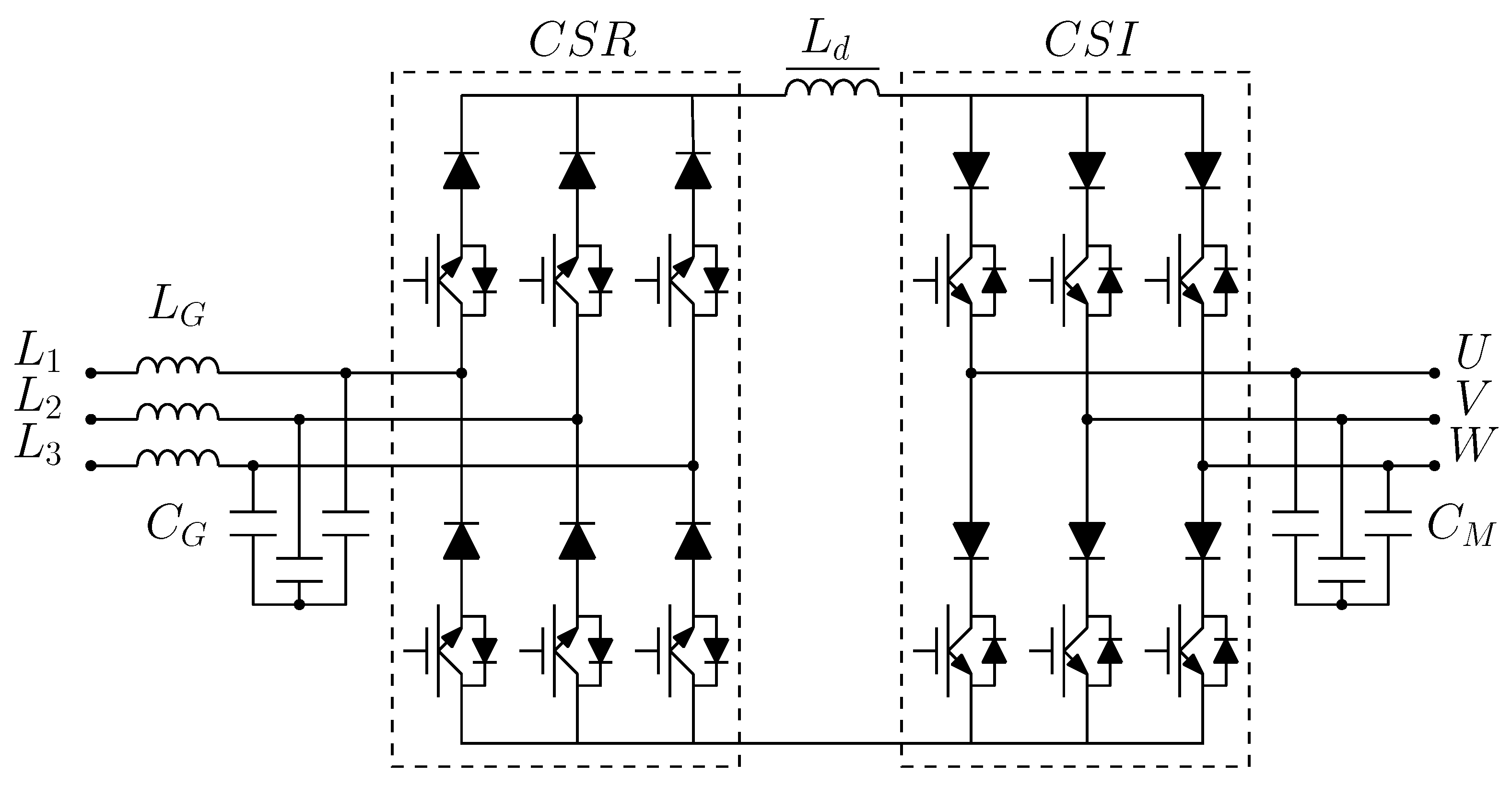
2. Doubly Fed Induction Generator System Model

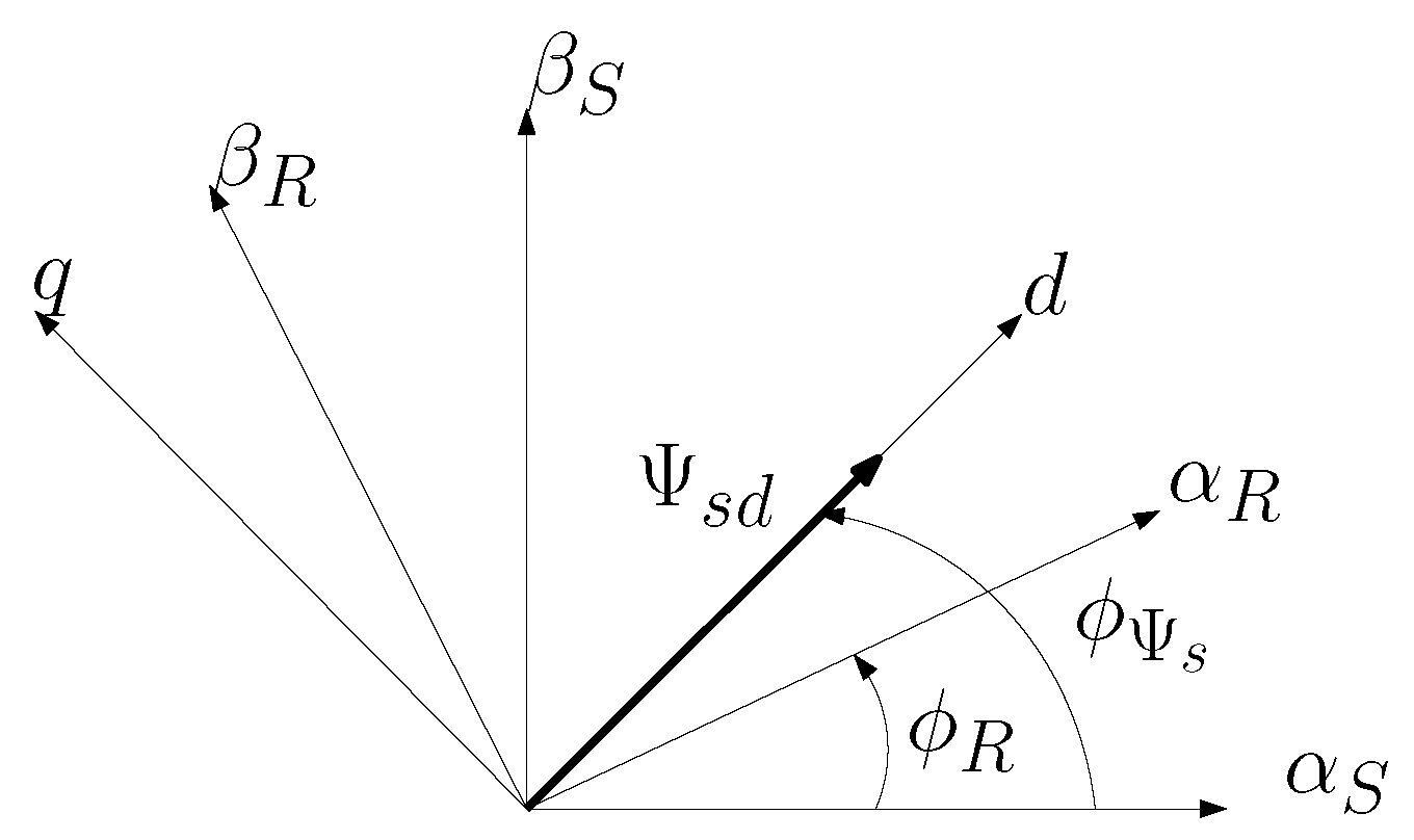
2.1. Field-Oriented Control

The most popular approach to the control of DFIG has been taken from the squirrel-cage machine. It is based on the field orientation (rotor or stator flux vector) of the machine state variables [7,8]. The voltage and flux equations of the DFIG (stator and rotor), in the Park reference frame, are derived directly from equations of the induction machine shown in Appendix A.
Assuming that the d-q coordinate system is bound to the stator flux vector (as shown in Figure 1), one can define Ψ s q = 0 and Ψ s d = Ψ s :
Equations (A6) and (A7) can be written as:
Ψ s d = L s i s d + L m i r d
Ψ s q = 0 = L s i s q + L m i r q
From these equations, the stator current components can be formed as:
i s d = 1 L s Ψ s L m i r d
i s q = L m L s i r q
The stator active and reactive powers are written in d-q coordinates:
p s = u s d i s d + u s q i s q
q s = u s q i s d u s d i s q
Additionally, considering only steady state, one can assume approximations: u s d 0 and u s q = u s Ψ s ω s . After that Equations (5) and (6) can be rewritten as:
p s = Ψ s L m ω s L s i r q
q s = Ψ s 2 ω s L s Ψ s L m ω s L s i r d
If one assumes that ω s = 1 (p.u.), one gets a simplified version of these equations:
p s = Ψ s L m L s i r q
q s = Ψ s 2 L s Ψ s L m L s i r d
Finally, from Equations (9) and (10), one can deduce relations for rotor current components:
i r q = L s p s Ψ s L m
i r d = Ψ s L m L s Ψ s L m q s
Then, additional decoupling variables were introduced to improve the quality of regulation (better tracking of setpoints and minimalization of errors). Those variables are derived from active and reactive power equations. The final set of control variables for the modulator block is as follows:
u 1 = 1 L m L s L m m 2
u 2 = L s L m m 1
Variables m 1 and m 2 can be defined as outputs of PI controllers:
m 1 = k p P r e f p s + k i P r e f p s d t
m 2 = k p Q r e f q s + k i Q r e f q s d t
where k p and k i denotes controllers gains, P r e f , Q r e f are reference values of active and reactive powers.

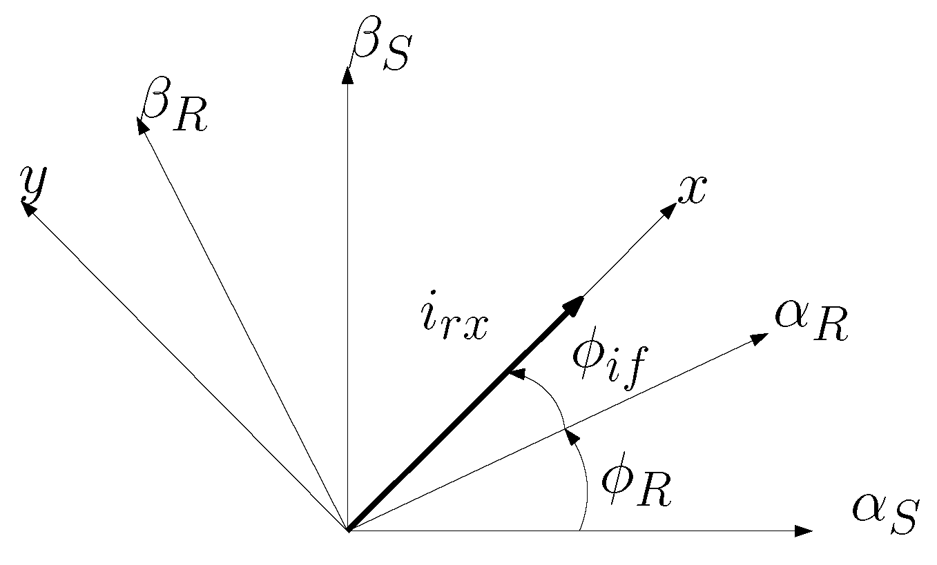
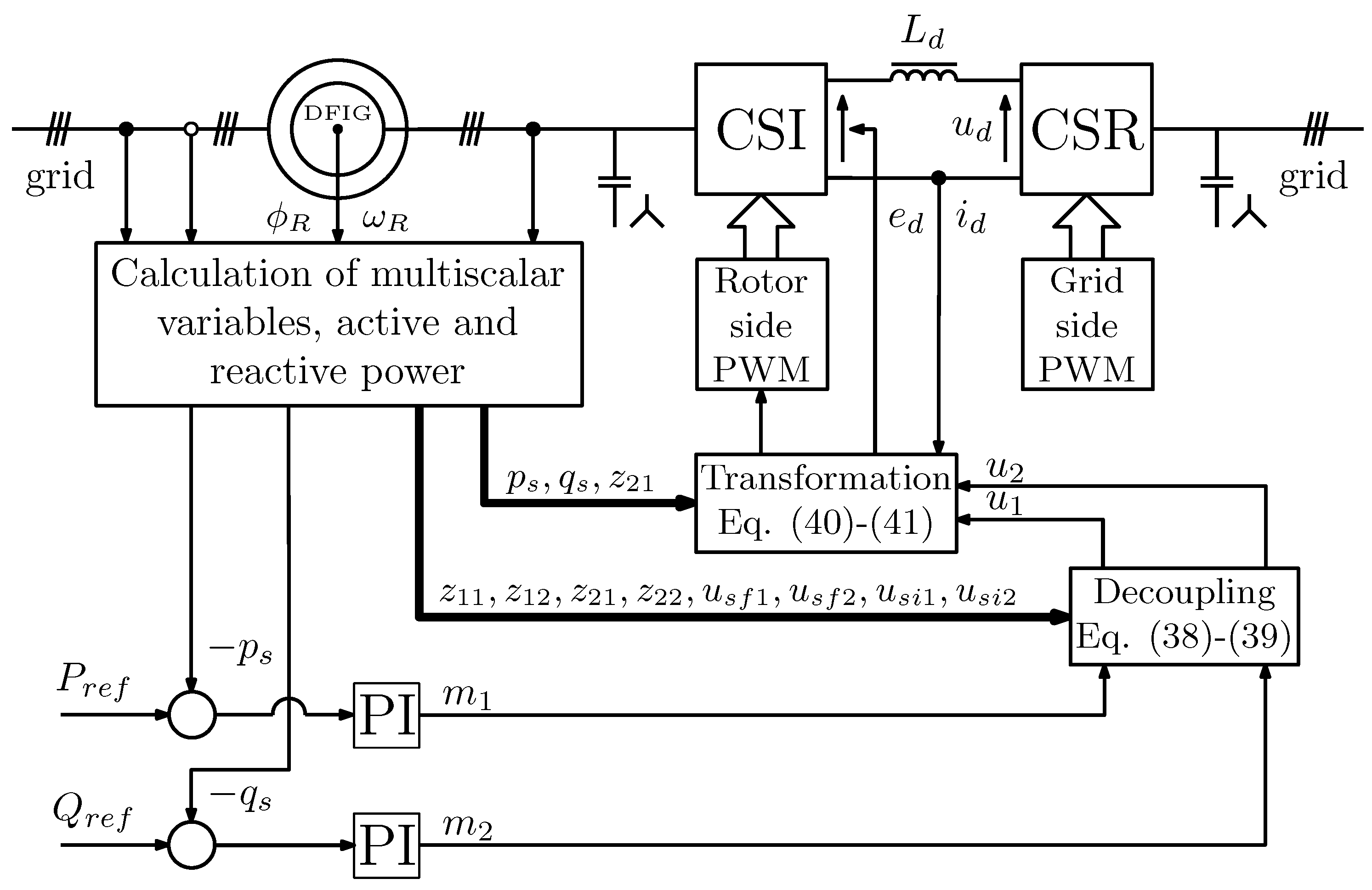
2.2. DFIG Control System Based on Active and Reactive Powers

In the latest literature, many articles present nonlinear control methods of Voltage Source Converters in conjunction with Doubly Fed Induction Generator [16,17,18,19]. It is easy to adapt those methods to the control system of DFIG supplied by Current Source Converters. In the approach proposed by the authors, the dynamics of the Doubly Fed Induction Generator in a vector form are represented in any possible reference frame rotating at ω a [23]. The authors have chosen reference frame x-y with x-axis oriented with inverter output current vector i r :
d ψ s x d τ = R s L s ψ s x + R s L m L s i r x + ω a ψ s y + u s x
d ψ s y d τ = R s L s ψ s y + R s L m L s i r y ω a ψ s x + u s y
d i r x d τ = L s 2 R r + L m 2 R s L s w δ i r x + R s L m L s w δ ψ s x + ω a ω r i r y + L m w δ ω r ψ s y + L s w δ u r x L m w δ u s x
d i r y d τ = L s 2 R r + L m 2 R s L s w δ i r y + R s L m L s w δ ψ s y ω a ω r i r x + + L m w δ ω r ψ s x + L s w δ u r y L m w δ u s y
d ω r d τ = L m J L s ψ s x i r y ψ s y i r x 1 J m 0
and:
w δ = L s L r L m 2
where R s and R r are the stator and rotor resistance, L s , L r , L m are the stator, rotor and mutual inductance, ψ s , u s indicate stator flux and voltage vectors and i r , u r represent rotor current and voltage vectors, ω r denotes rotor angular speed, ω a denotes the angular speed of rotation of the coordinate system. Figure 2 shows the vector orientation of the reference frame.
Assuming that the control variables are the DC-link input voltage e d and frequency of output current ω i r , it is possible to maintain the reference values of powers. That approach grants controllability of DC-link current and gives better use of grid power. Assuming a very small output capacitance, one can define u r x = u d , i r x = i d and i r y = 0 . The equation describing the dynamics of the DC link will be:
u r x = e d i r x R d L d d i r x d t
After taking into account Equation (23), the final set of DFIG differential equations in rotating reference frame x-y is as follows:
d ψ s x d τ = a 11 ψ s x + a 12 i r x + ω i + ω r ψ s y + u s x
d ψ s y d τ = a 11 ψ s y ω i + ω r ψ s x + u s y
d i s x d t = b 11 ψ s x + B i r i r x + b 13 ω r ψ s y + b 14 u s x + b 15 ω i ψ s y b 16 e d
d i s y d t = b 21 ψ s y b 22 ω i ψ s x b 23 ω r ψ s x + b 24 u s y
d i r x d τ = c 11 i r x + c 12 ψ s x c 13 ω r ψ s y + c 14 e d c 15 u s x
d ω r d τ = L m J L s ψ s y i r x 1 J m 0
where:
a 11 = R s L s , a 12 = R s L m L s , b 11 = R s L s 2 + R s L m 2 L s 2 L x , b 13 = 1 L s + L m 2 L s L x , b 14 = L m 2 L s L x + 1 L s , b 15 = 1 L s , b 16 = L m L x , b 21 = R s L s 2 , b 22 = b 23 = b 24 = 1 L s , c 11 = L s 2 R r + L m 2 R s + R d L s 2 L s 2 L x , c 12 = R s L m L s L x , c 13 = c 15 = L m L x , c 14 = L s L x , B i r = R s L m L s 2 + L m L s 2 R r + L m 3 R s + L m R d L s 2 L s 3 L x , L x = w δ + L d L s
The stator active and reactive power can be defined as:
p s = u s x i s x + u s y i s y
q s = u s y i s x u s x i s y
For steady-state operation of machine, vector components of flux can be defined as ψ s x u s y ω s , ψ s y u s x ω s and ω s 1 (p.u.), where ω s is the angular speed of grid voltage vector and is assumed constant during tests [24]. Using these dependencies, Equations (30) and (31) can be rewritten as:
p s = ψ s y i s x ψ s x i s y
q s = ψ s x i s x ψ s y i s y
Assuming (24)–(29), (32) and (33), differential equations of powers can be written as:
d p s d t = a 11 p s + ω r + 1 q s R s L m 2 L s 2 L x ψ s x ψ s y + B i r i r x ψ s y + 1 L s ω r z 21 + + 1 L s z 21 a 12 i r x i s y + L m 2 L s L x ω r ψ s y 2 + u s x ψ s y + u 1
d q s d t = a 11 q s ω r + 1 p s a 12 i r x i s x + R s L s 2 z 21 + R s L m 2 L s 2 L x ψ s x 2 + B i r i r x ψ s x L m 2 L s L x ω r ψ s y ψ s x + u s x ψ s x + u 2
where:
u 1 = 1 L s ω i z 21 + ω i q s L m L x e d ψ s y , u 2 = ω i p s + L m L x e d ψ s x , z 12 = ψ s y i r x z 21 = ψ s x 2 + ψ s y 2 , z 22 = ψ s x i r x
Using Static State Feedback Law to differential Equations (34) and (35) the following form of equations can be obtained:
d p s d t = 1 T p s + m 1 d q s d t = 1 T q s + m 2
where:
m 1 = u 1 + ω r + 1 q s R s L m 2 L s 2 L x ψ s x ψ s y + B i r i r x ψ s y + 1 L s ω r z 21 + + 1 L s z 21 a 12 i r x i s y + L m 2 L s L x ω r ψ s y 2 + u s x ψ s y
m 2 = u 2 ω r + 1 p s a 12 i r x i s x + R s L s 2 z 21 + R s L m 2 L s 2 L x ψ s x 2 + B i r i r x ψ s x L m 2 L s L x ω r ψ s y ψ s x + u s x ψ s x
Obtained variables m 1 and m 2 are new controls and taking form showed in (15) and (16). Variables u 1 and u 2 present in (34) and (35) are used to compensate the coupling between new state variables in the presented system:
u 1 = m 1 ω r + 1 q s + R s L m 2 L s 2 L x ψ s x ψ s y B i r i r x ψ s y 1 L s ω r z 21 + L m 2 L s L x ω r ψ s y 2 + u s x ψ s y 1 L s z 21 + a 12 i r x i s y
u 2 = m 2 + ω r + 1 p s + a 12 i r x i s x R s L s 2 z 21 R s L m 2 L s 2 L x ψ s x 2 + + B i r i r x ψ s x + L m 2 L s L x ω r ψ s y ψ s x + u s x ψ s x
These variables are also used to calculate the control variables for the system:
e d = L x z 21 + L s q s u 2 + L s p s u 1 L m ψ s x z 21 + L s q s L s ψ s y p s
ω i r = L s ψ s x u 1 + ψ s y u 2 ψ s x z 21 + L s q s L s ψ s y p s
Diagram of the nonlinear control system for Doubly Fed Induction Generator supplied by Current Source Converter is shown in Figure 3, analyzed structure of the Current Source Converter (consisting of Current Source Rectifier and Current Source Inverter) is shown in Figure 4.
The assumption made for the steady state that ψ s x u s y ω s , ψ s y u s x ω s and ω s 1 makes that the active and reactive power defined as (30) and (31) can be rewritten by (32) and (33). By calculating the derivatives of (32) and (33) another form of differential equations is obtained, on the basis of which variables u 1 and u 2 can be defined using the Static State Feedback Law (38) and (39), and control variables e d and ω i r defined by Equations (40) and (41). The control variables e d and w i r together with the Static State Feedback Law specified Equations (36) and (37) allow for decoupling the control subsystems (active power from reactive power), which will be confirmed in simulation tests.

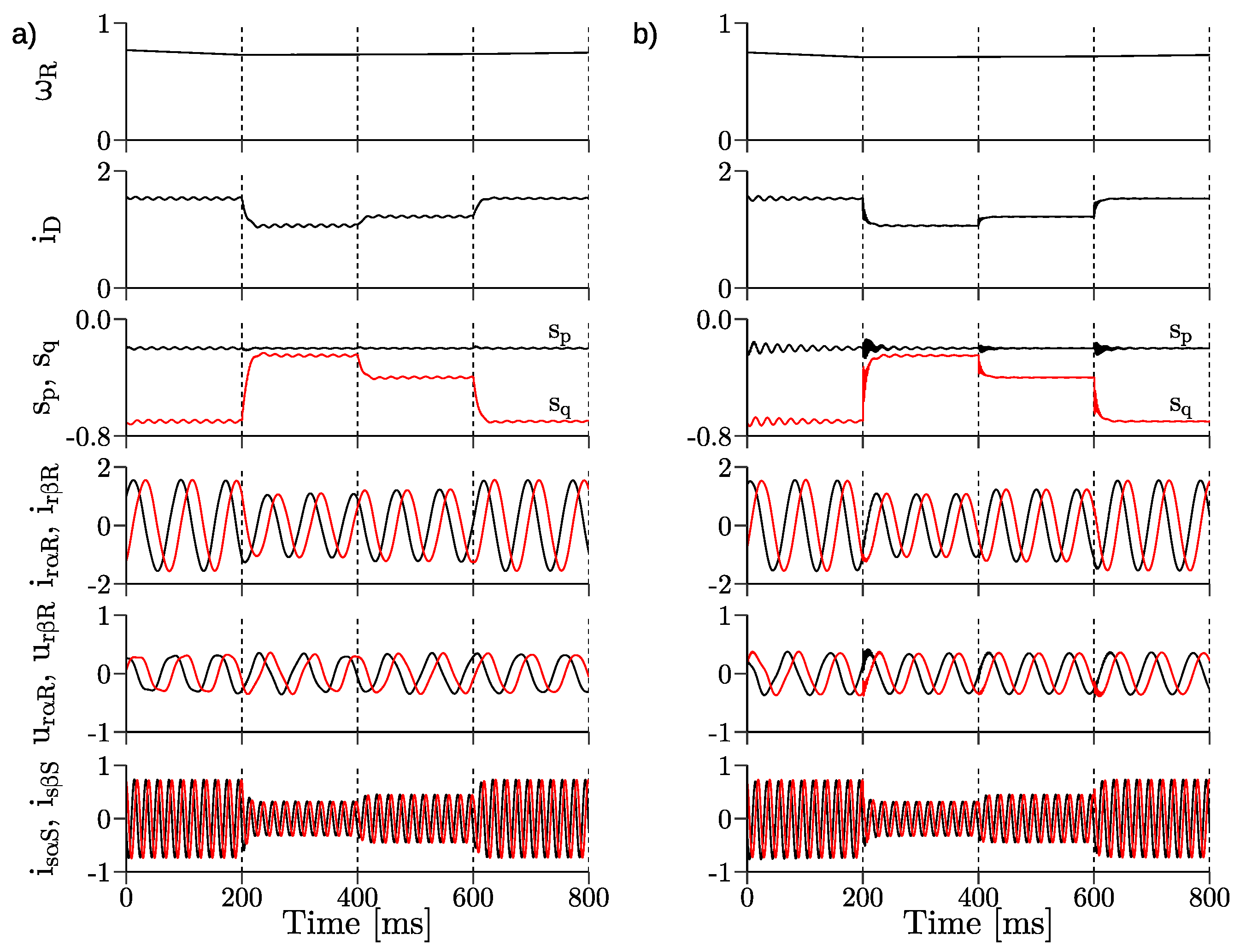
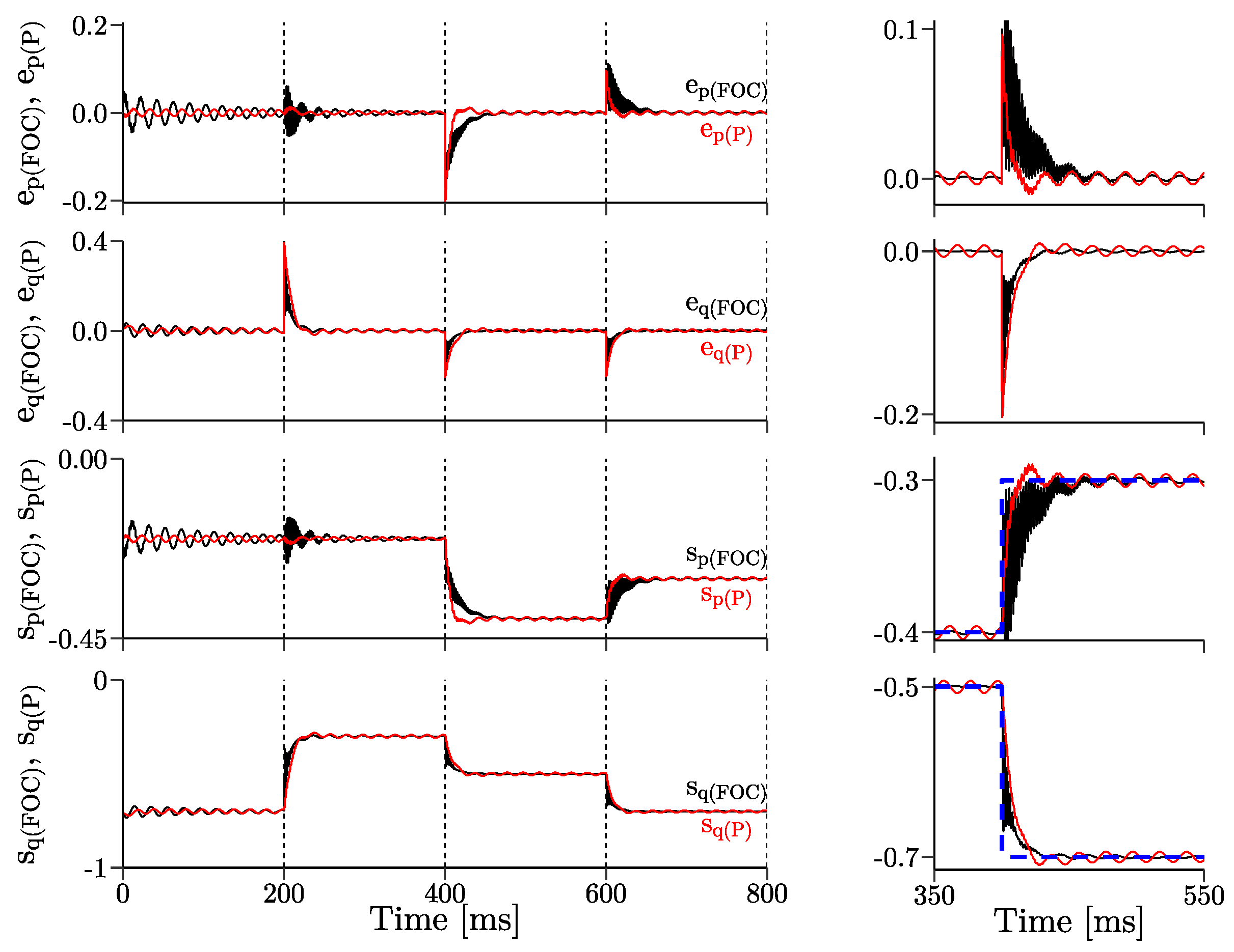
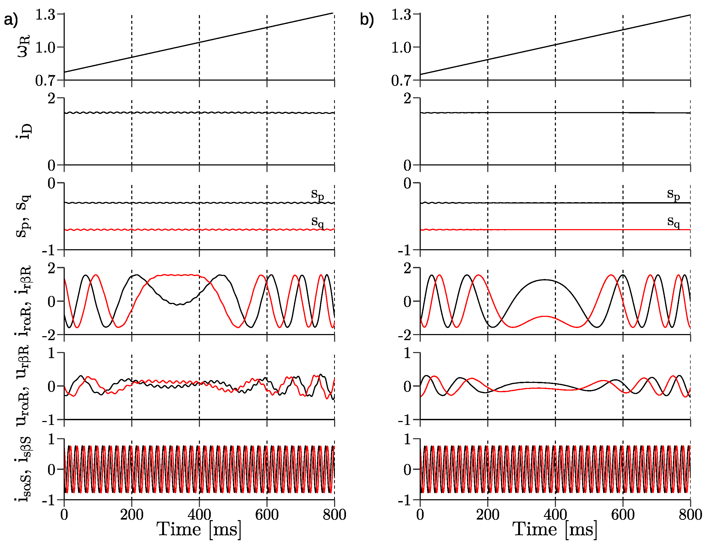
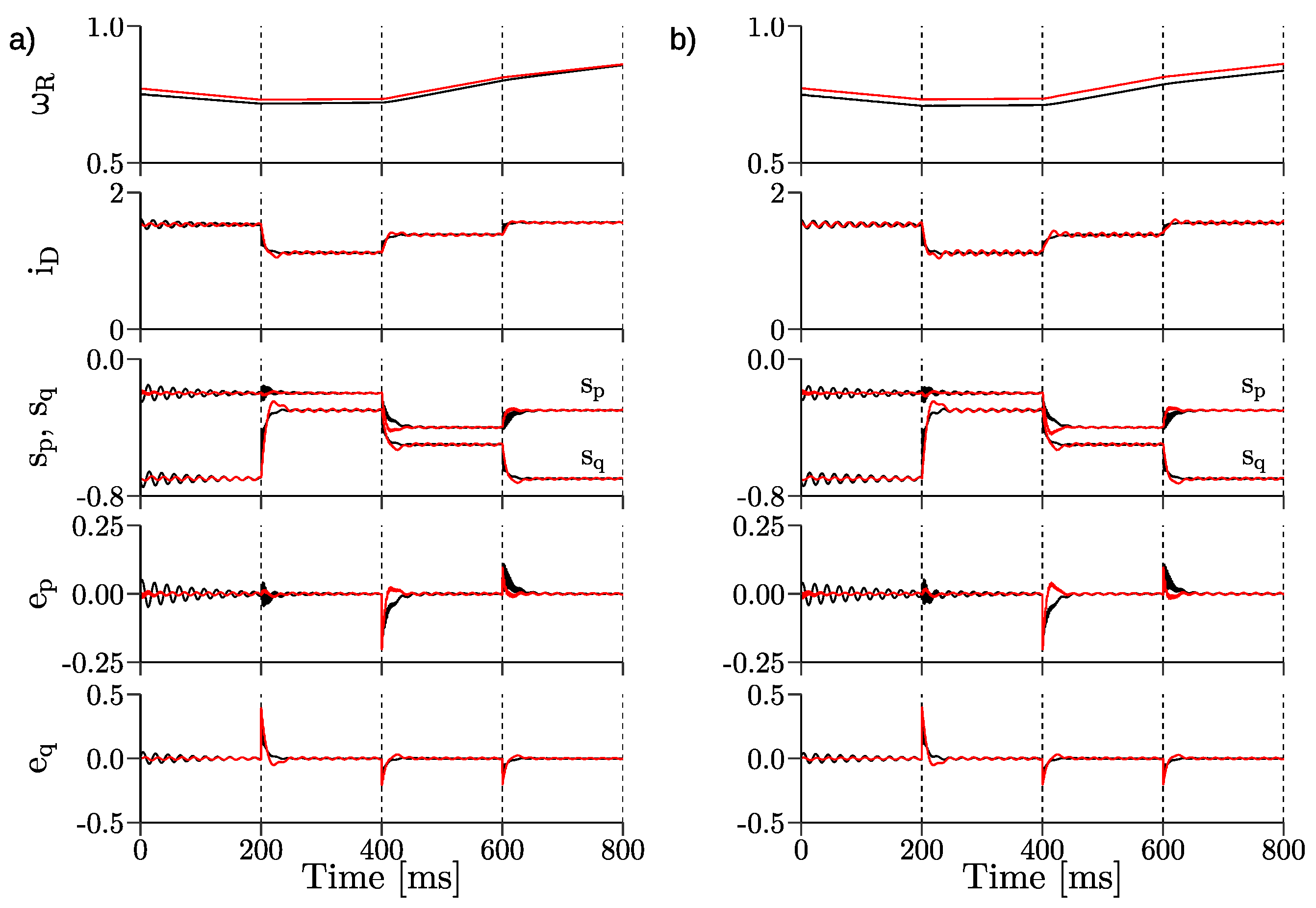
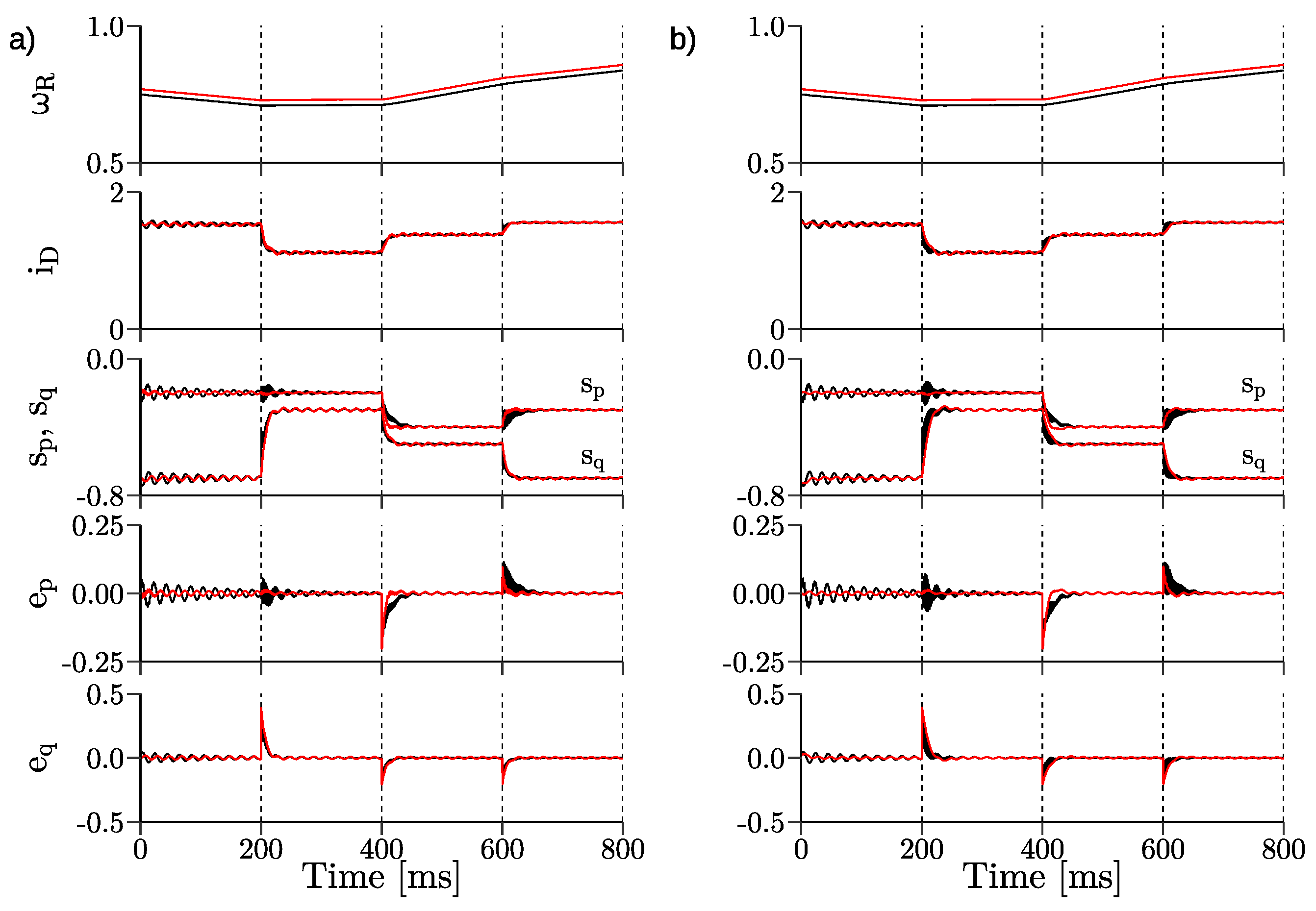
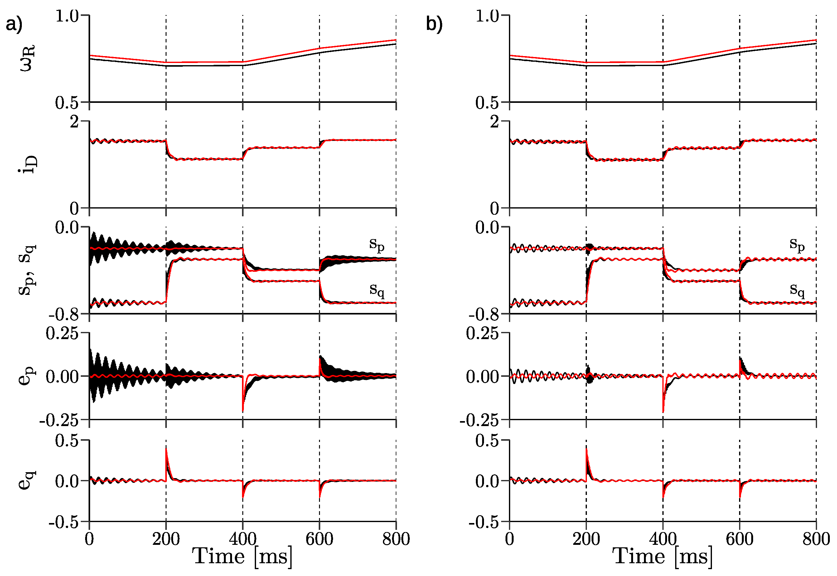
3. Simulation Results

Simulation studies were performed to analyze the operation of the proposed control system based on active and reactive powers and nonlinear transformations of variables. Simulation results were obtained by using a program written by the research team. Tuning gains of PI controllers in Field-Oriented Control and nonlinear control system are shown in Table 1 and the parameters of the simulation model and processor interrupt (PWM) period are presented in Table 2 (both in p.u.).
In the simulations, the authors carried out comparative tests of four DFIG system scenarios:
  • changes of the reference active power;
  • changes of the reference reactive power;
  • simultaneous changes of the reference active and reactive powers;
  • changes of the rotor speed from under-synchronous to over-synchronous speed with constant reference active and reactive powers;
  • uncertainties of DFIG nominal parameters for both control systems.
Figure 5a presents the reference active power change in the following four steps: after 0 s the reference is set to s p = −0.2 p.u., after 0.2 s: s p = −0.1 p.u., after 0.4 s: s p = −0.2 p.u., after 0.6 s: s p = −0.3 p.u. The waveforms have small oscillations during changes of reference values. Figure 5b presents the same tests for Field-Oriented Control. Despite comparable dynamics during changes, grater oscillations in transition states are visible. Also, the nonlinear Control System is fully decoupled. Waveforms of components i r α , β , i s α , β and i D C and stator active and reactive powers s p , s q are presented for the rotor speed ω r = 0.8 p.u.
Figure 6a presents the reference reactive power change in the following four steps: after 0 s the reference is set to s q = −0.7 p.u., after 0.2 s: s q = −0.25 p.u., after 0.4 s: s q = −0.4 p.u., after 0.6 s: s q = −0.7 p.u. The waveforms have small oscillations during changes of reference values. Figure 6b presents the same tests for Field-Oriented Control. Both systems have similar dynamics during changes, but Field-Oriented Control has more oscillations during transitions.
Figure 7a also presents the reference active and reactive powers changes in the following four steps: after 0 s the references are set to s p = −0.2 p.u., s q = −0.7 p.u., then after 0.2 s: s p =−0.2 p.u., s q = −0.3 p.u., then after 0.4 s: s p = −0.4 p.u., s q = −0.5 p.u., after 0.6 s: s p = −0.3 p.u., s q = −0.7 p.u. The waveforms have small oscillations during changes of reference. There are small overshoots in the s q . Figure 7b shows the same waveforms for Field-Oriented Control. Despite comparable dynamics variables, s p and s q have grater oscillations during transitions.
Direct comparison of Field-Oriented Control and nonlinear control system structures and transient states during simultaneous powers changes are shown in Figure 8. Despite the satisfactional dynamics of the Field-Oriented Control system, it has a high number of oscillations during transient states. These transient oscillations can be reduced by changing the gains. However, with these changes, the control system will not be able to reach the setpoints. Another advantage of the proposed power control structure can be seen in its great stability at high demand of power.
In Figure 9a the reference active and reactive powers are shown and forced: s p = −0.3 p.u., s q = −0.7 p.u. The rotor speed is changed from 0.7 to 1.3 p.u. The control system is stable near the synchronous speed of 1.0 p.u. In Figure 9b the same waveforms as in Figure 9a are shown for Field-Oriented Control. The control system is stable near synchronous speed (1.0 p.u.).
In Figure 10 the robustness of both control system structures under uncertainties of nominal values of stator and rotor resistance of DFIG is checked. Figure 10 also presents the reference active and reactive powers change in the following four steps: after 0 s the references are set to s p = −0.2 p.u., s q = −0.7 p.u., then after 0.2 s: s p = −0.2 p.u., s q = −0.3 p.u., then after 0.4 s: s p = −0.4 p.u., s q = −0.5 p.u., after 0.6 s: s p = −0.3 p.u., s q = −0.7 p.u. In Figure 10a in 0 s the stator resistance is changed to R s = 1.5 R s N (+50%) and in Figure 10b the rotor resistance is changed to R r = 1.5 R r N (+50%). The oscillations of e P and e Q have similar values in both cases; however, the control structures are stable. In both cases, stator and rotor resistance changes, Field-Oriented Control has greater oscillations in transient states.
In Figure 11 the robustness of both control system structures under uncertainties of nominal values of inductor L d is considered. Figure 11 also presents the reference active and reactive powers change in the following four steps: after 0 s the references are set to s p = −0.2 p.u., s q = −0.7 p.u., then after 0.2 s: s p = −0.2 p.u., s q = −0.3 p.u., then after 0.4 s: s p = −0.4 p.u., s q = −0.5 p.u., after 0.6 s: s p = −0.3 p.u., s q = −0.7 p.u. In Figure 11a in 0 s the value of inductor L d is set to L d = 0.5 L d N (−50%) and in Figure 11b the value of inductor L d is set to L d = 1.5 L d N (+50%). The oscillations of e P and e Q have similar values in both cases; however, the control structures are stable. In both cases, Field-Oriented Control has greater oscillations in transient states. In the case of power control, the value of inductor current ripples is smaller than 0.02 p.u. during transient states.
In Figure 12 the robustness of both control systems under uncertainties of nominal values of the output filter capacitance is checked. Figure 12 also presents the reference active and reactive powers change in the following four steps: after 0 s the references are set to s p = −0.2 p.u., s q = −0.7 p.u., then after 0.2 s: s p = −0.2 p.u., s q = −0.3 p.u., then after 0.4 s: s p = −0.4 p.u., s q = −0.5 p.u., after 0.6 s: s p = −0.3 p.u., s q = −0.7 p.u. In Figure 12a in 0 s the output filter capacitance to C m = 0.5 C m N (−50%) and in Figure 12b the output filter capacitance to C m = 2 C m N (+100%). The oscillations of e P and e Q have similar values in both cases; however, the control structures are stable. In the case of smaller capacitance, it was necessary to change gain values for active power in the Field-Oriented Control method from k p P = 0.45 and k i P = 0.3 to k p P = 0.3 and k i P = 0.25. Without that change the oscillations are not fading.

4. Conclusions

In this paper, the nonlinear control structure of the DFIG with the CSC system is presented. The comparative studies of the nonlinear control structure and Field-Oriented Control (presented in the simulation results–Section 3), confirmed that relative to Field-Oriented Control, the nonlinear control approach makes the DFIG system: be fully decoupled, have very good dynamic responses, have less distorted transition states. Oscillations do not appear in the system dynamics when the nonlinear control scheme is deplored. Minimal deterioration of some of the control structural properties is visible during the uncertainty states of nominal parameters of DFIG. However, the controlled DFIG-CSC system was always stable in the performed simulation tests. The proposed control system structure will be extended and implemented in the laboratory setup in the future. The interesting area of research is the reliability of the current converter system with the DFM of the ride-through fault, which was studied for the voltage source converter with DFM in [39]. Such an investigation will be conducted in the future.

Author Contributions

Conceptualization, M.M., P.K.; software, P.K.; validation, M.M.; investigation, M.M., P.K.; writing—original draft preparation, P.K.; writing—review and editing, A.J., M.M., C.O.; visualization, P.K.;funding acquisition, A.J.; All authors carried out the theoretical analysis and contributed to writing the paper. All authors have read and agreed to the published version of the manuscript.

Funding

This research received no external funding.

Institutional Review Board Statement

Not applicable.

Informed Consent Statement

Not applicable.

Data Availability Statement

Not applicable.

Conflicts of Interest

The authors declare no conflict of interest.

Appendix A

u s d = R s i s d + d Ψ s d d τ ω a Ψ s q
u s q = R s i s q + d Ψ s q d τ + ω a Ψ s d
u r d = R r i r d + d Ψ r d d τ ω a ω r Ψ r q
u r q = R r i r q + d Ψ r q d τ ω a ω r Ψ r d
d ω r d τ = L m J L s ψ s d i s q ψ s q i s d 1 J m 0
Ψ s d = L s i s d + L m i r d
Ψ s q = L s i s q + L m i r q
Ψ r d = L r i r d + L m i s d
Ψ r q = L r i r q + L m i s q
where R s and R r are the stator and rotor resistance, L s , L r , L m are the stator, rotor and mutual inductance ψ s , u s , i s indicate stator flux, voltage and current vectors and ψ r , u r , i r represent rotor flux, voltage and current vectors, ω r denotes rotor angular speed, ω a denotes the angular speed of rotation of the coordinate system.

References

  1. Burton, T.; Sharpe, D.; Jenkins, N.; Bossanyi, E. Wind Energy Handbook; John Wiley & Sons Ltd.: Chichester, UK, 2001. [Google Scholar]
  2. Fortmann, J. Modeling of Wind Turbines with Doubly Fed Generator System; Springer: Duisburg, Germany, 2014. [Google Scholar]
  3. Pillai, S.K.; Desai, K.M. A static scherbius drive with chopper. IEEE Trans. Ind. Electron. Control Instrum. 1977, 24, 24–29. [Google Scholar] [CrossRef]
  4. Smith, G.A.; Nigim, K.A. Wind-energy recovery by a static Scherbius induction generator. IEE Proc. C 1981, 128, 317–324. [Google Scholar] [CrossRef]
  5. Prasad, R.M.; Mulla, M.A. A Novel Position-Sensorless Algorithm for Field-Oriented Control of DFIG With Reduced Current Sensors. IEEE Trans. Sustain. Energy 2019, 10, 1098–1108. [Google Scholar] [CrossRef]
  6. Kakosimos, P.; Sarigiannidis, A.G.; Beniakar, M.; Kladas, A.; Gerada, C. Induction Motors Versus Permanent-Magnet Actuators for Aerospace Applications. IEEE Trans. Ind. Electron. 2014, 61, 4315–4325. [Google Scholar] [CrossRef]
  7. Aydin, E.; Polat, A.; Ergene, L.T. Vector Control of DFIG in Wind Power Applications. In Proceedings of the 5th International Conference on Renewable Energy Research and Applications, Birmingham, UK, 20–23 November 2016; pp. 478–483. [Google Scholar]
  8. Ihedrane, Y.; El Bekkali, C. Direct and Indirect Field Oriented Control Of DFIG-Generators for Wind Turbines Variable-Speed. In Proceedings of the 14th International Multi-Conference on Systems, Signals & Devices (SSD), Marrakech, Morocco, 28–31 March 2017; pp. 27–32. [Google Scholar]
  9. Erazo-Damián, I.; Apsley, J.M.; Perini, R.; Iacchetti, M.F.; Marques, G.D. Stand-Alone DFIG FOC Sensitivity and Stability Under Mismatched Inductances. IEEE Trans. Energy Convers. 2019, 34, 860–869. [Google Scholar] [CrossRef]
  10. Koczara, W.; Przybylski, J.; Drechsler, H. Oriented Control in the Drive System Double-Fed Machine (DFM). IFAC Proc. Vol. 1987, 20, 381–385. [Google Scholar] [CrossRef]
  11. Miller, N.W.; Sanchez-Gasca, J.J.; Price, W.W. Dynamic modeling of ge 1.5 and 3.6 mw wind turbine-generators for stability simulations. In Proceedings of the Power Engineering Society General Meeting, Toronto, ON, Canada, 13–17 July 2003; Volume 7, pp. 1977–1983. [Google Scholar]
  12. Benbouhenni, H.; Boudjema, Z. Two-level DTC based on ANN controller of DFIG using 7-level hysteresis command to reduce flux ripple comparing with traditional command. In Proceedings of the 2018 International Conference on Applied Smart Systems (ICASS), Medea, Algeria, 24–25 November 2018; pp. 1–8. [Google Scholar]
  13. Bakou, Y.; Abid, M.; Harrouz, A.; Yaichi, I.; Colak, I.; Kayisli, K.; Aissaoui, A. DTC Control of the DFIG, Application to the Production of Electrical Energy. In Proceedings of the 2019 8th International Conference on Renewable Energy Research and Applications (ICRERA), Brasov, Romania, 3–6 November 2019; pp. 910–915. [Google Scholar]
  14. Li, Y.; Hang, L.; Li, G.; Guo, Y.; Zou, Y.; Chen, J.; Li, J.; Zhuang, J.; Li, S. An improved DTC controller for DFIG-based wind generation system. In Proceedings of the 2016 IEEE 8th International Power Electronics and Motion Control Conference (IPEMC-ECCE Asia), Hefei, China, 22–26 May 2016; pp. 1423–1426. [Google Scholar]
  15. Ouezgan, K.; Bossoufi, B.; Bargach, M.N. DTC Control of DFIG-Generators for Wind Turbines: FPGA Implementation Based. In Proceedings of the 2017 International Renewable and Sustainable Energy Conference (IRSEC), Tangier, Morocco, 4–7 December 2017; pp. 1–6. [Google Scholar]
  16. Singh, P.; Kaur, A. Power control of Doubly Fed Induction Generator (DFIG) using back to back converters (PWM technique). In Proceedings of the 2014 IEEE International Conference on Advanced Communications, Control and Computing Technologies, Ramanathapuram, India, 8–10 May 2014; pp. 73–77. [Google Scholar]
  17. Demirbas, S.; Bayhan, S. Active and reactive power control of doubly fed induction generator using direct power control technique. In Proceedings of the 4th International Conference on Power Engineering, Energy and Electrical Drives, Istanbul, Turkey, 13–17 May 2013; pp. 41–45. [Google Scholar]
  18. Soares Pereira, B.S.; Luis Maia Santos, T. Speed and Reactive Power Regulation of Doubly-fed Induction Generator using Model Predictive Control. In Proceedings of the 2018 Workshop on Communication Networks and Power Systems (WCNPS), Brasília, Brazil, 7–9 November 2018. [Google Scholar]
  19. Alaya, J.B.; Khedher, A.; Mimouni, M.F. Nonlinear vector control strategy applied to a variable speed DFIG generation system. In Proceedings of the Eighth International Multi-Conference on Systems, Signals & Devices, Sousse, Tunisia, 22–25 March 2011; pp. 1–8. [Google Scholar]
  20. Mestri, M.N.; Kumar, B.S. Design of 9-Switch Converter for DFIG System for Active and Reactive Power Control by PID and Fuzzy Logic Controller. In Proceedings of the 2019 3rd International conference on Electronics, Communication and Aerospace Technology (ICECA), Coimbatore, India, 12–14 June 2019. [Google Scholar]
  21. Ramadan, A.; Kamel, S.; Rashad, A.; Yu, J. Design of Fuzzy Logic Control for Direct and Quadratic Components of DFIG’s Rotor and Grid Side Control System Based Wind Turbines. In Proceedings of the 2018 Twentieth International Middle East Power Systems Conference (MEPCON), Cairo, Egypt, 18–20 December 2018; pp. 655–659. [Google Scholar]
  22. Geniusz, A.; Krzemiński, Z. Control System Based on the Modified Multiscalar Model for the Double Fed Machine; Centrum Usług Informatycznych Politechniki Gdańskiej: Gdańsk, Poland, 2005. [Google Scholar]
  23. Bogalecka, E. Power control of a double fed induction generator without speed or position sensor. In Proceedings of the Fifth European Conference on Power Electronics and Applications, Brighton, UK, 13–16 September 1993; pp. 224–228. [Google Scholar]
  24. Krzemiński, Z. Sensorless multiscalar control of double fed machine for wind power generators. In Proceedings of the Power Conversion Conference-Osaka 2002, Osaka, Japan, 2–5 April 2002; pp. 334–339. [Google Scholar]
  25. Bogalecka, E.; Krzemiński, Z. Control systems of doubly-fed induction machine supplied by current controlled voltage source inverter. In Proceedings of the Sixth International Conference on Electrical Machines and Drives, Oxford, UK, 8–10 September 1993; pp. 168–172. [Google Scholar]
  26. Hailemariam, Z.M.; Leidhold, R.; Tesfamariam, G.T. Real-Time Speed Control of a PMSM for Wind Turbine Application. In Proceedings of the 2019 IEEE PES/IAS PowerAfrica, Abuja, Nigeria, 20–23 August 2019; pp. 396–401. [Google Scholar]
  27. Gang, Y.; Yichang, G.; Lidan, Z.; Dongdong, L.; Xing, L. Multi-Phase Permanent Magnet Synchronous Generator Variable Speed Constant Frequency Offshore Wind System Based on Modular Multilevel Converter. In Proceedings of the 2019 IEEE Innovative Smart Grid Technologies - Asia (ISGT Asia), Chengdu, China, 21–24 May 2019; pp. 2127–2132. [Google Scholar]
  28. Djagarov, N.; Grozdev, Z.; Enchev, G.; Djagarova, J. Study of Low-Voltage Ride Through of Wind Permanent Magnet Synchronous Generator by means of STATCOM. In Proceedings of the 2019 20th International Scientific Conference on Electric Power Engineering (EPE), Kouty nad Desnou, Czech Republic, 15–17 May 2019; pp. 1–6. [Google Scholar]
  29. Solomon, O. The Design, Control and Dynamic Performance of an Interior Permanent Magnet Synchronous Generator for Wind Power System. In Proceedings of the IECON 2018-44th Annual Conference of the IEEE Industrial Electronics Society, Washington, DC, USA, 21–23 October 2018; pp. 714–718. [Google Scholar]
  30. Klumpner, C.; Blaabjerg, F. Using reverse-blocking IGBTs in power converters for adjustable-speed drives. IEEE Trans. Ind. Appl. 2006, 42, 807–816. [Google Scholar] [CrossRef]
  31. Takei, M.; Harada, Y.; Ueno, K. 600 V-IGBT with reverse blocking capability. In Proceedings of the Proceedings of the 13th International Symposium on Power Semiconductor Devices & ICs. IPSD ’01 (IEEE Cat. No.01CH37216), Osaka, Japan, 7 June 2001; pp. 413–416. [Google Scholar]
  32. Xu, Y.; Wang, Z.; Liu, P.; Song, Q.; Tang, C.; Cheng, M. Zero-Voltage Switching Current-Source-Inverter Motor Drives Based on Silicon Carbide Devices. In Proceedings of the 22nd Inter. Conference on Electrical Machines and Systems (ICEMS), Harbin, China, 11–14 August 2019. [Google Scholar]
  33. Barth, H.; Hofmann, W. Potentials and Boundaries of Discrete SiC-Transistors in AC Drives. In Proceedings of the 2018 20th European Conference on Power Electronics and Applications (EPE’18 ECCE Europe), Riga, Latvia, 17–21 September 2018. [Google Scholar]
  34. Villagrán-Valencia, L.J.; Ramírez-Hernández, J.; Mondragón-Escamilla, N.; Araujo-Vargas, I. Analysis of Bidirectional Switching of SiC Transistors in a Matrix Converter Leg. In Proceedings of the 2018 IEEE International Conference on Electrical Systems for Aircraft, Railway, Ship Propulsion and Road Vehicles & International Transportation Electrification Conference (ESARS-ITEC), Nottingham, UK, 7–9 November 2018; pp. 1–5. [Google Scholar]
  35. Sahan, B.; Araújo, S.V.; Noding, C.; Zacharias, P. Comparative evaluation of three-phase current source inverters for grid interfacing of distributed and renewable energy systems. IEEE Trans. Power Electron. 2011, 26, 2304–2318. [Google Scholar] [CrossRef]
  36. Ryndzionek, R.; Sienkiewicz, Ł. Evolution of the HVDC Link Connecting Offshore Wind Farms to Onshore Power Systems. Energies 2020, 13, 1914. [Google Scholar] [CrossRef] [Green Version]
  37. Ma, J.; Zhao, D.; Yao, L.; Qian, M.; Yamashita, K.; Zhu, L. Analysis on application of a current-source based DFIG wind generator model. CSEE J. Power Energy Syst. 2018, 4, 352–361. [Google Scholar] [CrossRef]
  38. Blecharz, K.; Morawiec, M. Nonlinear control of a doubly fed generator supplied by a current source inverter. Energies 2019, 12, 2335. [Google Scholar] [CrossRef] [Green Version]
  39. Abobkr, A.H.; El-Hawary, M.E. Fault ride-through capability of doubly-fed induction generators based wind turbines. In Proceedings of the 2015 IEEE Electrical Power and Energy Conference, London, ON, Canada, 26–28 October 2015; pp. 8–15. [Google Scholar]
Figure 1. Coordinate system orientation for Field-Oriented Control.
Energies 14 01511 g001
Figure 2. System orientation in α β S and α β R coordinates.
Energies 14 01511 g002
Figure 3. Nonlinear control structure of the Doubly Fed Induction Generator.
Energies 14 01511 g003
Figure 4. Structure of the current converter.
Energies 14 01511 g004
Figure 5. Simulation results of active power step responses in: (a) the nonlinear control system, (b) the Field-Oriented Control system.
Energies 14 01511 g005
Figure 6. Simulation results of reactive power step responses in: (a) the nonlinear control system, (b) the Field-Oriented Control system.
Energies 14 01511 g006
Figure 7. Simulation results of active and reactive power step responses in: (a) the nonlinear control system, (b) the Field-Oriented Control system.
Energies 14 01511 g007
Figure 8. Simulation results of active and reactive power step responses—comparison.
Energies 14 01511 g008
Figure 9. Simulation results of system behavior during changes of rotor speed from subsynchronus to supersynchronous with constant active and reactive powers for: (a) the nonlinear control system, (b) the Field-Oriented Control system.
Energies 14 01511 g009
Figure 10. DFIG system behavior during changes of active and reactive powers under uncertainties of (a) R s = 1.5 R s N (b) R r = 1.5 R r N (FOC in black, power control in red).
Energies 14 01511 g010
Figure 11. DFIG system behavior during changes of active and reactive powers under uncertainties of (a) L d = 0.5 L d N (b) L d = 1.5 L d N (FOC in black, power control in red).
Energies 14 01511 g011
Figure 12. DFIG system behavior during changes of active and reactive powers under uncertainties of (a) C m = 0.5 C m N (b) C m = 2 C m N (FOC in black, power control in red).
Energies 14 01511 g012
Table 1. Tuning gains of Field-Oriented Control and nonlinear control System.
Gain NameField-Oriented Control (Value)Nonlinear Control (Value)
k p P 0.451.5
k i P 0.30.6
k p Q 0.81.25
k i Q 0.70.4
Table 2. DFIG with Current Source Converter System parameters and reference unit.
SymbolNameValues
R s stator resistance2.741 Ω /0.0649 p.u.
R r rotor resistance3.212 Ω /0.0762 p.u.
L m magnetizing inductance0.17 H/1.2733 p.u.
L s , L r stator and rotor inductance0.195 H/1.3378 p.u.
P n nominal power2 kW
I n s nominal stator current5.5 A
I n r nominal rotor current3.4 A
U n nominal stator voltage400 V
nnominal rotor speed910 rpm
fnominal frequency50 Hz
rturn ratio N s / N r 1
L d DC choke inductance12.4 mH/0.1 p.u.
C m output filter capacitance100 µF/0.125 p.u.
U b reference voltage400 V
I b = 3 I n s reference current9.52 A
S b reference power3.81 kVA
T i m p converters PWM period150 ms
Publisher’s Note: MDPI stays neutral with regard to jurisdictional claims in published maps and institutional affiliations.

