Article

A Numerical Study on Hydrodynamic Energy Conversions of OWC-WEC with the Linear Decomposition Method under Irregular Waves

1
Korea Research Institute of Ships and Ocean Engineering (KRISO), Deajeon 34103, Korea
2
Department of Convergence Study on Ocean Science and Technology, Ocean Science and Technology School, Korea Maritime and Ocean University, Busan 49112, Korea
*
Author to whom correspondence should be addressed.
Energies 2021, 14(6), 1522; https://doi.org/10.3390/en14061522
Submission received: 4 January 2021 / Revised: 23 February 2021 / Accepted: 27 February 2021 / Published: 10 March 2021
(This article belongs to the Section A3: Wind, Wave and Tidal Energy)

Abstract

:
A numerical study was performed to investigate the applicability of the linear decomposition method for the hydrodynamic energy conversion of an oscillating-water-column type wave energy converter (OWC-WEC). Hydrodynamic problems of the OWC chamber were decomposed into the excitation and radiation problems with the time-domain numerical method based on the linear potential theory. A finite element method was applied to solve the potential flow in the entire fluid domain including OWC chamber structure. The validity of the linear decomposition method was examined by comparing with the direct interaction method for the turbine–chamber interaction based on the linear pressure drop characteristics. In order to estimate the hydrodynamic energy conversion performance under the irregular waves, the response spectrum method was applied with the transfer function based on the linear decomposition method. Under the various irregular wave conditions, the pneumatic power of OWC-WEC calculated by the response spectrum based on the linear decomposition method agreed well with the direct irregular wave simulation results.

1. Introduction

A wave energy converter (WEC) generates electric power by converting the input wave energy using its components. Various types of WEC have been studied that can be classified according to the wave energy conversion mechanism [1,2,3], such as attenuator; point absorber; terminator. The oscillating-water-column type WEC (OWC-WEC) is one of the terminator type WECs, which has been widely used due to its simplicity: the only moving part of the power take-off (PTO) system is the rotor of a turbine, located above the water level, rotating at a relatively high velocity and directly driving a conventional electrical generator [4,5]. Additionally, there is an effort to integrate the OWC-WEC with the conventional breakwater to enhance the economic feasibility of the device [6,7,8,9,10].
The concept of hydrodynamic energy conversion of an OWC-WEC is shown in Figure 1. The OWC chamber converts wave motion into the oscillating motion of the fluid contained inside the chamber structure. The air volume change inside the chamber due to free-surface motion induces a reciprocating airflow through the air turbine connected to the chamber. The power take-off system, including an air turbine, a generator, and a power conversion system, converts the pneumatic power to electric power. During the energy conversion process, an air turbine rotation causes a pressure drop, which acts as a damping force on the free-surface inside the chamber that suppresses the water column motion. The interaction between turbine and chamber has a dominant effect on the hydrodynamic energy conversion performance of the OWC-WEC.
Theoretical descriptions for solving the hydrodynamic energy conversion problem of OWC devices have been proposed based on the linear potential theory, in which the hydrodynamic problem was decomposed into a scattering (or diffraction) problem corresponding to the interaction between an incident wave and OWC chamber without pressure fluctuations and a radiation problem regarding exciting pressure inside a chamber in the still water [11,12,13]. Various numerical methods have been introduced to solve the hydrodynamic problems of a land-based OWC chamber and the boundary value problems of the fluid domain based on the potential theory, such as a Galerkin method for the scattering and radiation problems [14], a boundary element method (BEM) [15,16,17,18,19], a boundary integral equation method (BIEM) [20], a higher-order BEM (HOBEM) [21,22], and a finite element method (FEM) [5,10,23].
A time-domain numerical method is required to solve the turbine–chamber interaction, including the transient response analysis and the nonlinear pressure drop effects over time using the direct interaction modeling of the pressure drop on the dynamic free-surface condition. The nonlinear numerical wave tank technique was developed [17,18,21,22] to solve the nonlinear hydrodynamic problem in the time domain. Kim et al. [5] focused on the combination of a linear numerical wave tank with nonlinear pressure drops. However, it was also used to deal with the linear hydrodynamics problem of the OWC chamber because it is practical to intuitively understand the hydrodynamic response characteristics by applying the direct interaction method (DIM) even for nonlinear problems [5,16].
The objective of this study is an application of the linear decomposition method (LDM) to the estimation of the hydrodynamic energy conversion performance under irregular waves. The FEM was used to solve the Laplace equation of boundary value problem based on the linearized potential theory. The hydrodynamic problem was separated into the excitation and radiation problems to deal with the interaction problems of wave–structure and turbine–chamber individually. The validity and applicability of this decomposition approach are discussed by comparing with the DIM. The following sections describe the numerical method for the LDM and the numerical wave tank techniques. The obtained numerical simulation results are presented and discussed.

2. Numerical Methods

2.1. Linear Decomposition Method

The pneumatic power take-off system using the air turbines is commonly used in the OWC system. Figure 2 shows the flow diagram of the wave–chamber–turbine interaction mechanism of an OWC-WEC. The OWC chamber contributes to converting wave energy into pneumatic energy, and in the next energy conversion step, this pneumatic energy is converted into mechanical energy through the turbine’s rotational motion. The pressure drop caused by the turbine operation affects the oscillating-water-column motion as a damping force acting on it. Therefore, the energy conversion performance of the chamber is considerably dependent on the interaction between the pressure drop and the water column motion.
The turbine–chamber interaction problem can be distinguished into the radiation and excitation problems in terms of hydrodynamics. The radiation problem corresponds to the radiation waves on the calm water generated by an oscillating dynamic air pressure above the free-surface inside the chamber. The excitation problem deals with the oscillation of the water column and airflow generated by an incident wave when the dynamic air pressure is zero. In order to decompose the boundary value problem, the velocity potential is distinguished into the incident, the diffraction, and the radiation wave potential as shown in Equation (1). The diffraction and radiation wave potentials correspond to the disturbed wave potential. Similar decomposition can be applied to wave elevation ζ , as shown in Equation (2).
ϕ = ϕ I + ϕ D + ϕ R
ζ = ζ I + ζ D + ζ R
where the subscript I, D and R correspond to the incident, diffraction and radiation for the wave potential and elevation, respectively. The linear dynamic free-surface boundary condition can be decomposed into Equations (3) and (4) in terms of the excitation and radiation problems.
t ( ϕ I + ϕ D ) = g ( ζ I + ζ D )
t ϕ R = g ζ R p r ρ a
where g and ρ a are the gravitational acceleration constant and the air density constant, respectively. p r is the radiation pressure used as the excitation pressure in the forced radiation simulation, which corresponds to the aerodynamic pressure drop due to the turbine rotation. Figure 3 shows the schematic diagram of the decomposed hydrodynamic problem for the oscillating-water-column, i.e., excitation and radiation problems.
The volumetric flow rate of the air (i.e., airflow) generated from the oscillating internal water surface can be decomposed into the excitation and radiation airflow, i.e., Q E and Q R , as shown in Equation (5).
Q = Q E + Q R = S c z ( ϕ I + ϕ D ) d S + S c ϕ R z d S
By assuming that ϕ I and ϕ D are linear in wave amplitude A, and ϕ R is linear in radiation admittance Y ^ R , the airflow can be expressed as the complex amplitudes [13].
Q ^ = Q ^ E + Q ^ R = q ^ e A Y ^ r p ^ r
where
q ^ e = q e exp { i ( ω t ε q q e ) }
Y ^ r = Y r exp ( i ε q r p r )
p ^ r = p r exp { i ( ω t ε q q e ε q e q r ) }
q ^ e and Y ^ r correspond to the transfer function for the airflow from the incident wave and radiation pressure, respectively. The term ‘^’ indicates the complex amplitude. ε X Y is the phase difference from X to Y . The subscript q , q e , q r , and p r indicate the total airflow, excitation airflow, radiation airflow, and radiation pressure, respectively. ε q r p r can be found in the radiation problem. Then, total airflow Q ^ in Equation (6) can be expressed with sinusoidal time variation form as follows:
Q ^ = [ q e A Y r p r exp { i ( ε q e q r + ε q r p r ) } ] exp { i ( ω t ε q q e ) }
Equations (9) and (10) are the implicit function for the p r and ε q e q r under the assumption of an in-phase relationship between total airflow Q ^ and radiation pressure p ^ r . In these equations, the phase difference between excitation and radiation airflow ε q e q r is the variable for the amplitude of radiation pressure p r . Then, the pneumatic power can be estimated as follows based on the product of the pressure drop and airflow calculated by the LDM.
P ¯ p = 1 ω ω   p ^ r · Q ^ d ω
Figure 4 shows the concept of the linear decomposition method in terms of the pneumatic power. The absorbed pneumatic power corresponds to the difference between the excitation and radiation components.

2.2. Boundary Value Problem

The potential flow theory is used to solve the hydrodynamic energy conversion problem of an OWC-WEC by assuming an inviscid, incompressible fluid and irrotational flow. Figure 5 shows a definition of the boundary value problem for the present study. It is assumed that an OWC chamber structure is fixed on the seabed, and airflow can only pass through a turbine. The velocity potential surrounding the OWC chamber structure could be defined in the fluid domain. The linearized boundary value problem for a given wave-structure interaction problem is as follows.
2 ϕ = 0     in   Ω           (12)
ζ t = { ϕ z β ζ ϕ z     on   S F 1 on   S F 2           (13)
ϕ t = { g ζ β ϕ g ζ + p r ρ a     on   S F 1 on   S F 2           (14)
ϕ n = 0     on   S B   and   S W           (15)
The governing equation of the potential flow is the Laplace equation presented as Equation (12), where velocity potential is defined in the entire fluid domain Ω . The linearized kinematic and dynamic free-surface boundary conditions are presented in Equations (13) and (14). S F 1 and S F 2 correspond to the outer and inner free-surface of the OWC chamber, respectively. An artificial damping term is added to free-surface boundary conditions on the numerical damping zone to satisfy the radiation condition at the open boundary, in which an artificial damping coefficient β is only effective on the numerical damping zone [5]. The forced radiation pressure p r , i.e., pressure drop, is added to the dynamic free-surface boundary condition. Here, the air is assumed to be an incompressible gas. Equation (15) is the non-penetration boundary condition for the chamber structure ( S B ) and wall boundary condition on the seabed ( S W ).

2.3. Finite Element Method

In this study, the finite element method was applied to solve the given boundary value problem. The weak formulation of the governing equation could be obtained by applying integration by parts with test functions ψ as follows.
Ω ϕ · ψ d V Ω   ϕ n ψ d S = 0
After the fluid domain is discretized using a finite number of elements, the velocity potential function and wave elevation can be approximated as a linear summation of the continuous and differentiable test functions as follows:
ϕ ( x , y , z , t ) = i ϕ i ( t ) N i ( x , y , z )
ζ ( x , y , z , t ) = k ζ k ( t ) M k ( x , y )
where N i is a three-dimensional basis function defined in the entire fluid domain, and M k is a two-dimensional basis function on the free-surface. Eight-node hexahedral elements and four-node quadrilateral elements were used in this study. By applying the Galerkin method, the boundary value problem is finally obtained as the following linear algebraic equations:
K i j = F i
T i k ζ ˙ k = P i k ( ϕ n , k + f ζ , k )
T i k ϕ ˙ k = P i k ( g ζ k + f ϕ , k )
where
K i j = Ω   N i · N j d V
F i = S B   N i ϕ n d S
T i k = P i k = S F   M i M k d S
The solution of the Laplace equation is obtained from Equation (19). The free-surface velocity potential and elevation are integrated in time by using Equations (20) and (21). In this study, the fourth-order Adams–Bashforth–Moulton method was applied for the time integration of the free-surface boundary condition. The conjugate gradient method was employed for solving Equations (22)–(24).

3. Results and Discussions

3.1. Linear Decomposition Method (LDM) for OWC’s Hydrodynamic Energy Conversion

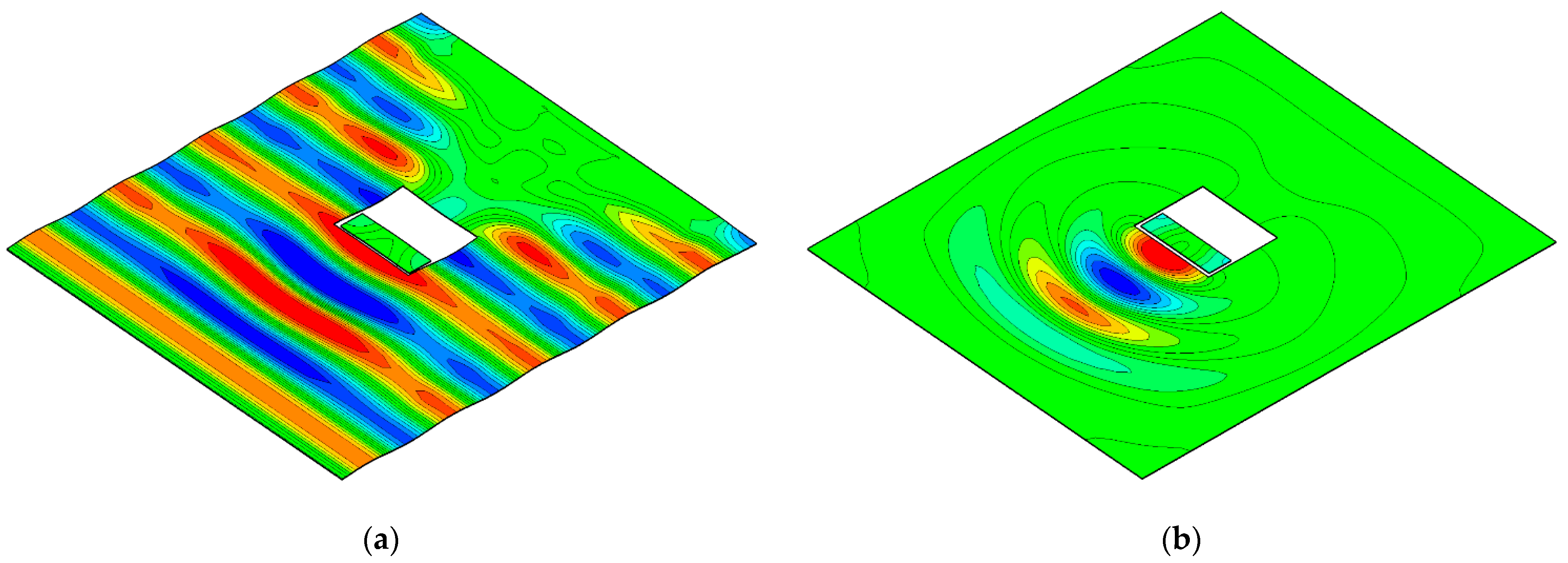
The radiation problem deals with the excitation force and resulting energy dissipation by the radiated waves outward on the calm water. In this case, the excitation force corresponds to the oscillating aerodynamic pressure acting on the free-surface inside the chamber. The excitation (or scattering) problem deals with the oscillating-water-column motion caused by the incident waves when the aerodynamic pressure is set to zero. Figure 6 shows the wave fields around the OWC chamber under both wave excitation and forced radiation simulation in the three-dimensional numerical wave tank, in which the numerical grid of the computational fluid domain constructed based on the recommendation of [5] corresponds to 81,855 nodes and 70,916 elements. The dimension of the OWC chamber model corresponds to water depth 16.5 m, breadth 34 m, and front wall depth 2 m.
Time-series data of free-surface elevation, pressure drop, and airflow measured in the chamber under excitation and radiation simulation are shown in Figure 7. The response of the OWC chamber excited at different frequencies ω = 1.0 and 1.5 rad/s are shown together. In order to express the relationship between the measured data, their amplitudes are expressed as a normalized value.
In the wave excitation simulation, the OWC chamber is modeled to allow the airflow caused by the free-surface oscillation to pass freely in and outside the chamber so that the Figure 7a,c shows the zero pressure drop. In the forced radiation simulation, the sinusoidal pressure variation excites the free-surface motion and produces the airflow. The oscillating airflow behaves out-of-phase with respect to the free-surface elevation. Additionally, the airflow is proportional to the vertical speed of the free-surface inside the chamber.
Figure 7b,d show that the phase difference between the exciting pressure and the resulting free-surface elevation in the forced radiation simulation is frequency-dependent. The free-surface elevation under the ω = 1.0 rad/s in Figure 7b behaved almost in-phase with the excitation pressure. However, the free-surface elevation under relatively high-frequency exciting pressure ω = 1.5 rad/s showed a clear phase difference from the excitation pressure, as shown in Figure 7d. Therefore, it was necessary to investigate the phase difference between the excitation pressure and the water column motion according to the wave frequency.
The pneumatic responses of the OWC chamber under wave excitation and forced radiation simulation are shown in Figure 8. The phase difference of pneumatic responses were defined based on the radiation airflow; these phase differences under various frequencies are shown in Figure 8a.
  • ε p r q r : phase difference from pressure drop to airflow in the forced radiation case;
  • ε q e q r : phase difference from wave excitation airflow to forced radiation airflow.
The phase difference can be estimated based on the physical process of the coupled turbine–chamber interaction in time under the constraint that total airflow, which is the sum of the excitation and radiation airflow, is in-phase with the radiation pressure. ε p r q r and ε q e q r showed frequency-dependent characteristics. ε p r q r is sensitive to the excitation frequency in the low-frequency side ( ω < 1.8 rad/s), where the fluid sloshing mode is dominant. ε q e q r showed the opposite pattern, which was sensitive on the high-frequency side ( ω > 1.8 rad/s).
Moreover, the phases of ε p r q r and ε q e q r changed rapidly in a narrow frequency band at around ω = 1.8, 2.5 rad/s in Figure 8a, in which wave frequencies corresponded to the first and second longitudinal sloshing modes in Figure 9, but the overall trend was soon recovered. In the free-surface inside the OWC chamber, the piston and sloshing modes appeared together according to the excitation wavelength, and as the wavelength increased, it showed similar characteristics to the flat piston mode. The free-surface profile depended on the relationship between the chamber’s longitudinal length and the incident wavelength [5,23].
Under the linear assumption, excitation and radiation airflow were proportional to incident wave amplitude and radiation pressure [13], respectively, and these are expressed as excitation airflow coefficient ( q e ) and radiation admittance ( Y r ) in Figure 8b. The q e and Y r showed similar tendency according to the wave frequency overall, including the condition of the first and second longitudinal sloshing mode in Figure 9, although the peaks of q e and Y r are slightly mismatched under the piston mode dominant condition, ω < 1.8 rad/s. The peak frequency of q e under the piston mode has appeared at a lower frequency than that of Y r , which can be interpreted as the effect of the standing wave around the OWC chamber. The standing wave developed by superposition of incident and diffracted waves affects the increasing effective water mass acting on the water column motion under the wave excitation simulation.
The excitation and radiation airflows can be calculated by applying q e with incident wave amplitude A and Y r with radiation pressure p r , respectively. The total airflow can be calculated using the phase differences with each decomposed airflow component based on Equation (7). The total airflow tends to gradually decrease as the radiation pressure increases in Figure 10a, and the available range of the radiation pressure is limited depending on the wave frequency. The pneumatic power calculated by the product of the total airflow and radiation pressure was also characterized as having an optimal value within the limited radiation pressure range, as shown in Figure 10b.
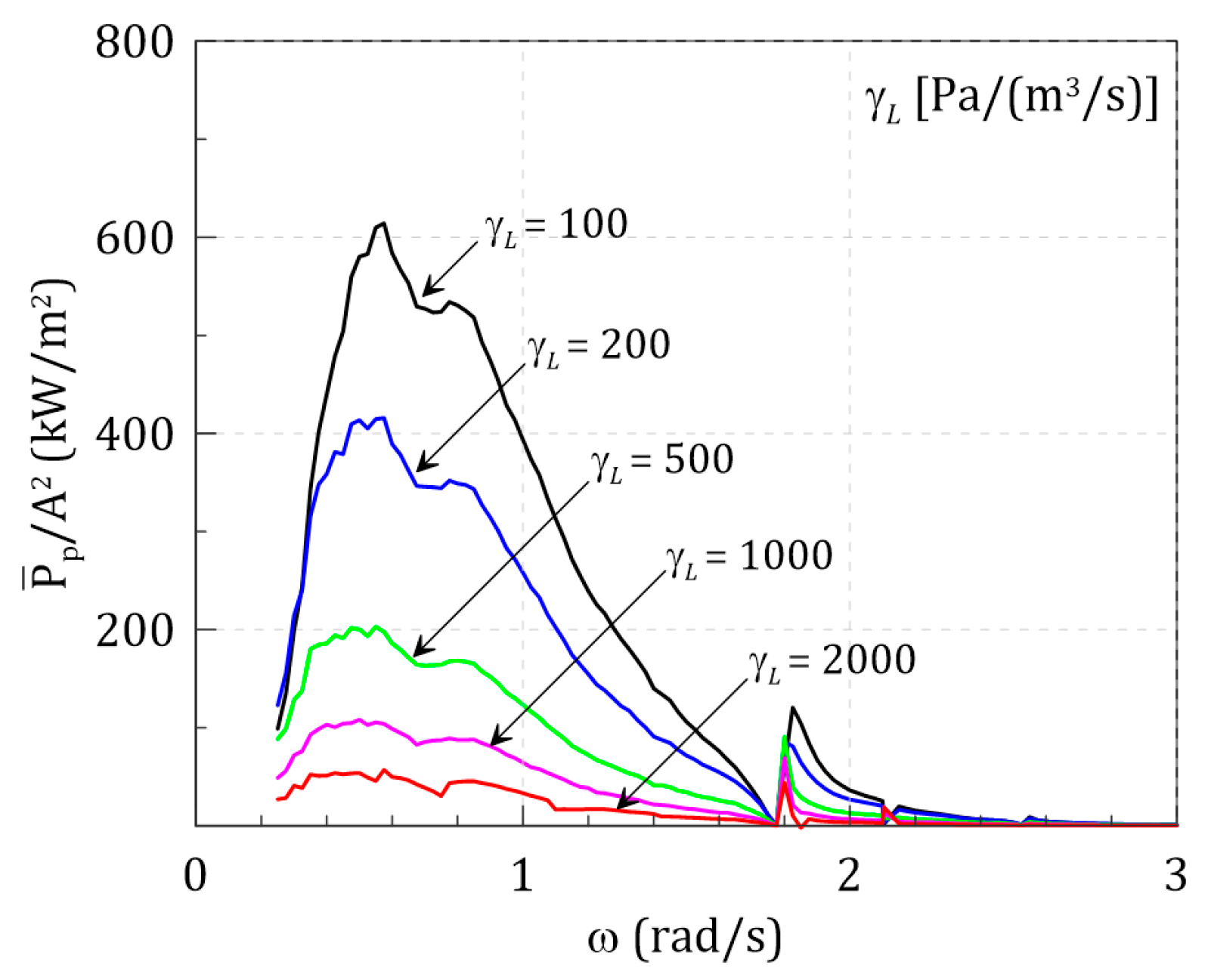
Figure 11 shows the pneumatic power of the OWC chamber under various pressure drop coefficients and wave frequencies. In general, the pressure drop coefficient represents the aerodynamic characteristics of an air turbine. Here, the pressure drop coefficient corresponds to the ratio of radiation pressure and total airflow as follows.
γ L = Q p r
As shown in Figure 10, the optimum pneumatic power appears at a specific radiation pressure for each wave frequency. Therefore, the pneumatic power for the wave frequency can differ depending on the pressure drop coefficient in Figure 11. It can be seen that the pressure drop due to the turbine operation and its interaction with the chamber has direct effect on the primary hydrodynamic energy conversion performance.

3.2. Comparison of Linear Decomposition Method (LDM) and Direct Interaction Method (DIM)

The direct interaction approach is a numerical method to calculate the hydrodynamic performance of the OWC chamber regarding the wave–chamber–turbine interactions, as shown in Figure 1. The turbine–chamber interaction problem can be modeled by continuously updating the pressure drop ( p d ) generated by the air turbine while the water column is excited by the incident wave. The pressure drop acts as a damping force on the free-surface inside the chamber, and is modeled as a linear function of the airflow in Equation (25), which corresponds to the fundamental aerodynamic characteristics of the Wells turbine under constant operating conditions.
Figure 12 shows the time-series data of the OWC chamber responses in a wave excitation simulation with DIM. The pressure drop is in-phase with the airflow, which corresponds to the out-of-phase free-surface elevation, as shown in Figure 12a. The pneumatic power has a positive value in Figure 12b, which can be calculated as the product of the in-phase airflow and pressure drop. Each time-series response is confirmed to converge to a quasi-steady state after a certain period.
The validity of the hydrodynamic energy conversion performance of OWC derived from the linear decomposition method was investigated through comparison with the direct interaction simulation results. The direct interaction method is a general numerical method to consider turbine–chamber interactions in previous studies. In this study, the direct interaction method was used for the benchmark test to examine the validity of the linear decomposition method.
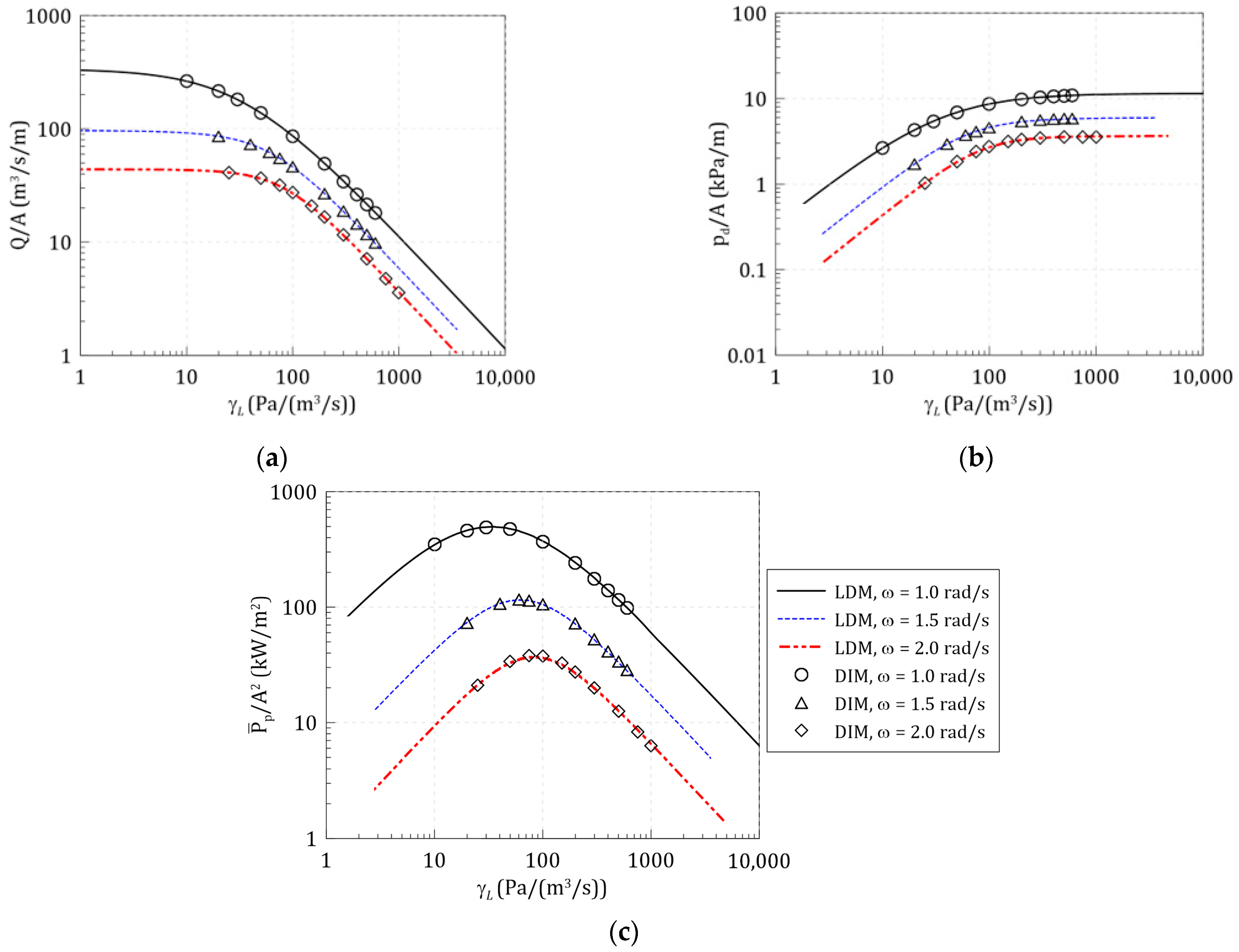
Figure 13 shows the comparison of the simulation results between the LDM and DIM according to the change of the linear pressure drop coefficient ( γ L ). The pneumatic responses of LDM are calculated for various radiation pressures based on the excitation airflow coefficient ( q e ) and radiation admittance ( Y r ) derived through wave excitation and forced radiation simulations under the three-wave frequencies, ω = 1.0, 1.5, 2.0 rad/s. For these wave frequencies, the DIM simulations were performed applying various linear pressure drop coefficients, and these are expressed as symbols in Figure 13. It was confirmed that the simulation results of LDM agree well with the DIM results at the wave frequencies regardless of the linear pressure drop coefficient.
The results of both numerical methods according to the wave frequency and the pressure drop coefficient are compared in Figure 14. The DIM simulation results (symbols) for various wave frequencies with three linear pressure drop coefficients are compared with the LDM simulation results (lines). The simulation results of both numerical methods agree well over the entire frequency domain, ω = 0.5 ~ 3.0 rad/s, including the longitudinal sloshing mode condition where the free-surface motion inside the chamber is complex. Therefore, it can be confirmed that the LDM and DIM under the linear assumption can obtain the equivalent estimation results for the OWC chamber hydrodynamic performance. Moreover, because the LDM can calculate the hydrodynamic energy conversion performance under various pressure drop characteristics using the wave excitation and forced radiation simulation results, it is a practical method that can significantly reduce the numerical simulation cases.

3.3. LDM-based Response Spectrum Method (RSM) for OWC’s Hydrodynamic Energy Conversion under Irregular Waves

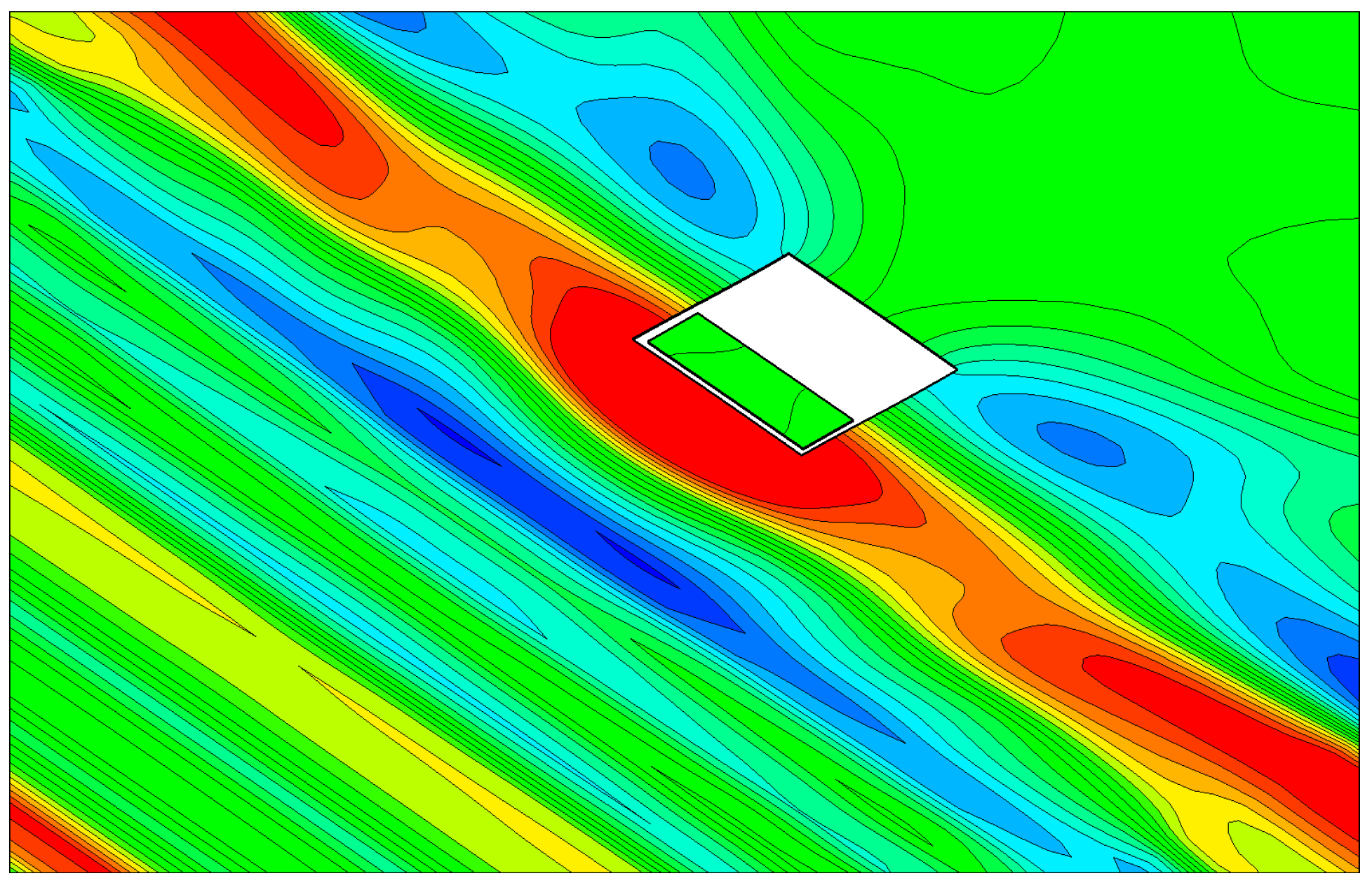
Wave energy converters operate under ocean waves; therefore, their energy conversion characteristics need to be investigated under irregular waves, as shown in Figure 15. This section will discuss introducing a response spectrum method (RSM) to estimate the hydrodynamic energy conversion performance of the OWC chamber under irregular waves. The OWC chamber’s performance is applied as a transfer function, corresponding to pneumatic power from the incident wave, calculated based on regular wave simulation with the LDM. The pneumatic power of the OWC chamber under irregular waves is estimated by the response spectrum, which corresponds to the product of transfer functions and wave spectra. The validity of the LDM-based RSM is investigated by comparing with the DIM simulation results under irregular waves.
The irregular waves were generated in the three-dimensional numerical wave tank based on the Pierson–Moskowitz spectrum [24] in Equation (26):
S w ( ω ) = 5 16 H s 2 ω p 4 ω 5 exp { 5 4 ( ω ω p ) 4 }
where H s is the significant wave height and ω p ( = 2 π / T p ) is the peak wave angular frequency.
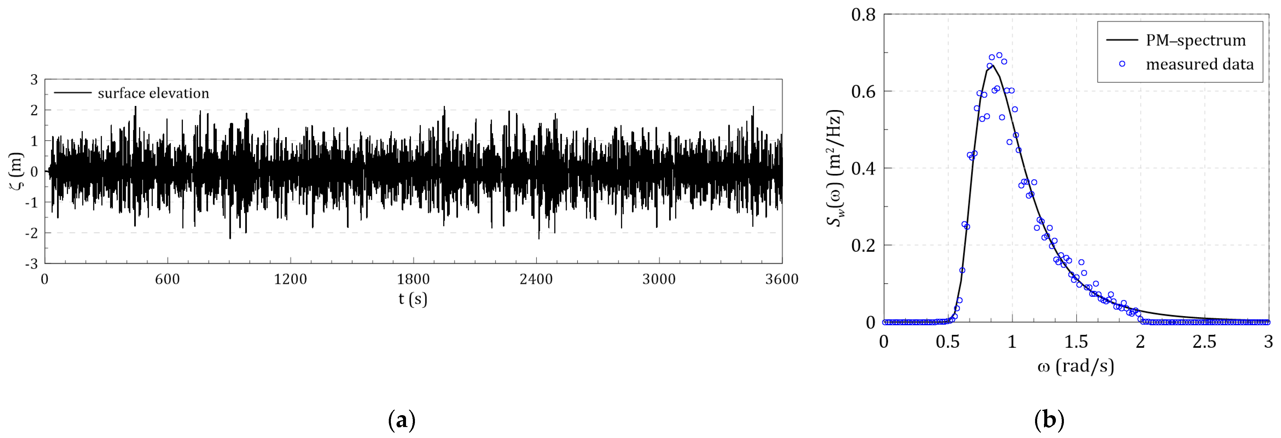
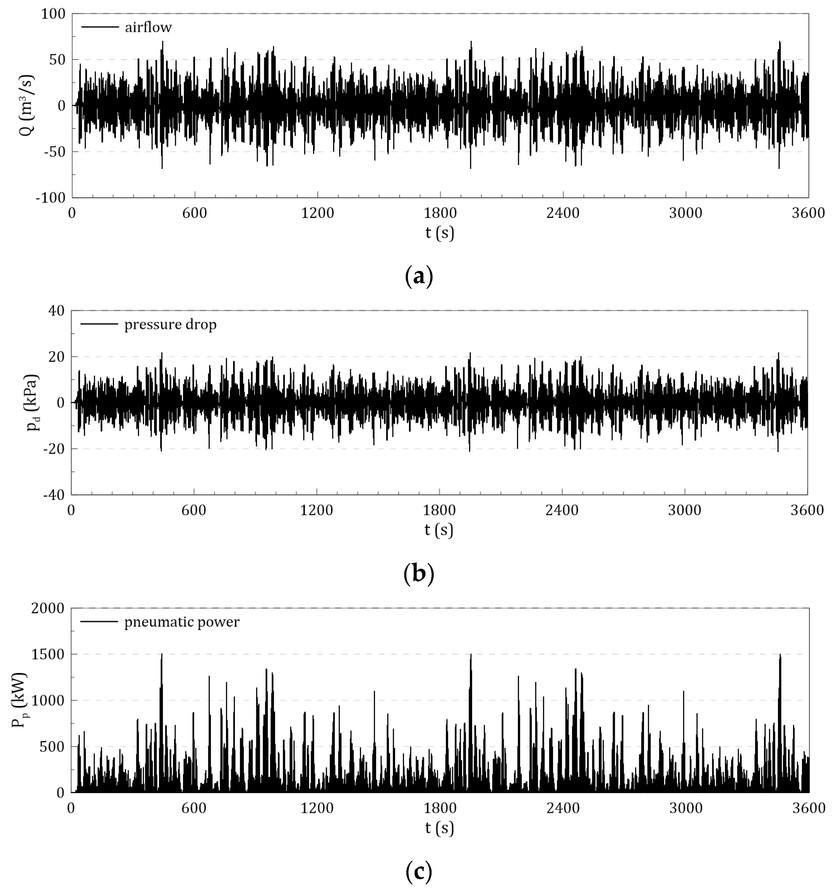
Figure 16 and Figure 17 show the example of the time-domain irregular wave simulation results, in which the incident wave condition corresponds to H s = 2.5 m and T p = 7.5 s, and the simulation time is set to 3600 s (1 h). An example of the time-series free-surface elevation measured in the numerical wave tank without the chamber structure is shown in Figure 16a. From the correspondence between the input theoretical spectrum and the measured wave spectrum shown in Figure 16b, it can be seen that the irregular wave is well generated in the numerical wave tank. Figure 17 shows the pneumatic responses of the OWC chamber, i.e., airflow, pressure drop, and pneumatic power, under irregular incident wave simulation with DIM based on Equation (14).
Wells turbines are characterized by a pressure drop linearly proportional to the flow rate [4]. Under the assumption of linear pressure drop, the energy conversion performance of the OWC chamber is dependent only on the excitation wave frequency, so the linear decomposition method and the RSM can be applied together. The response spectrum ( S R ) on the basis of frequency, ω , can be found from the transfer function ( G ) and the wave spectrum ( S w ) by [25]:
S R ( ω ) = G ( ω ) · S w ( ω )
G ( ω ) = P p ¯ ( ω ) 1 2 A 2
where the transfer function of the pneumatic power can be calculated by hydrodynamic simulation with DIM or LDM under a regular wave.
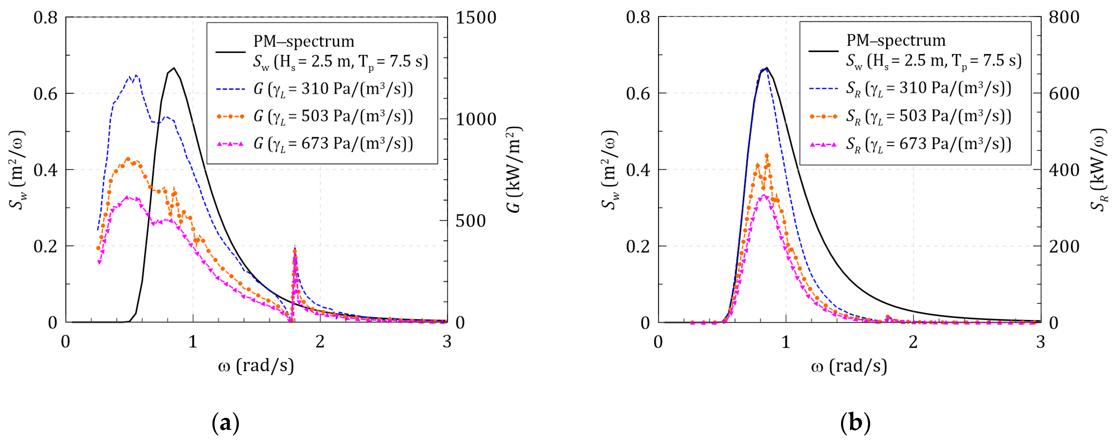
Figure 18a shows the pneumatic power transfer function and wave spectrum applying three arbitrary linear pressure drop. The response spectrum calculated by the product of the wave spectrum and transfer function based on Equation (27) is shown in Figure 18b. The transfer function’s peak frequency is lower than that of the wave spectrum, as shown in Figure 18a. Nevertheless, it can be seen that the peak frequency of the response spectrum is dependent on the wave frequency. In order to increase the pneumatic power under irregular waves, not only the pressure drop that can increase the magnitude of the transfer function must be applied, but it is also important that the peak frequency coincides with the peak frequency of the wave spectrum.
A physical quantity can be defined by moments of the response spectrum [25]. The mean pneumatic power can be defined as the zero-order moment of the response spectrum as follows.
P p ¯ = 0 S R ( ω ) d ω = m 0
In order to examine the validity of the LDM-based RSM, the numerical simulations were performed under the three irregular wave conditions with three linear pressure drop coefficients, as shown in Table 1.
Figure 19 shows the comparison results of the mean pneumatic power under irregular waves between the LDM-based RSM and DIM-based irregular wave simulation. The numerical simulation results of both methods show good agreement within the 5% relative error range under all nine simulation conditions. Therefore, it can be seen that the LDM-based RSM is quite a practical method for estimating the hydrodynamic performance of the OWC chamber connected to the Wells turbine under irregular waves. The application of this method is expected to contribute to reducing the computational time for numerical simulation.

4. Conclusions

The hydrodynamic energy conversion problems of the OWC-WEC have been investigated numerically, focusing on the hydrodynamic interactions with pressure drop. A numerical method has been developed based on a finite element method with the linear potential theory for wave excitation and forced radiation simulations. The linear decomposition method (LDM) was introduced to estimate the hydrodynamic energy conversion performance of the OWC chamber under various wave frequencies and pressure drop coefficients. An excitation airflow coefficient and a radiation admittance, which were derived from wave excitation and forced radiation simulations, respectively, were used to estimate the extracted pneumatic power with their phase relationship. The validity of the LDM was examined by numerically comparing the calculated pneumatic responses between the LDM and the direct interaction method (DIM).
The response spectrum method was applied to estimate the pneumatic power of the OWC chamber under irregular waves. The transfer functions of pneumatic responses were derived by the hydrodynamic simulation with the LDM under regular waves. The hydrodynamic energy conversions under irregular waves were estimated by the response spectrum method (RSM), considering the product of transfer functions and wave spectra. The mean pneumatic power estimated by applying the RSM agreed well with the 1 h irregular wave simulation result. Therefore, under the assumption of an air turbine’s linear pressure drop characteristics, it can be seen that the LDM-based RSM is applicable to estimate the hydrodynamic energy conversion performance of the OWC chamber in ocean waves.

Author Contributions

Formal analysis, J.P. and S.P.; project administration, K.-H.K.; supervision, S.H.S.; writing—original draft preparation, J.-S.K. All authors have read and agreed to the published version of the manuscript.

Funding

This research was supported by a grant from the Endowment Project of “Development of WECAN for the Establishment of Integrated Performance and Structural Safety Analytical Tools of Wave Energy Converter” funded by the Korea Research Institute of Ships and Ocean Engineering (PES3980). All support is gratefully acknowledged.

Conflicts of Interest

The authors declare no conflict of interest.

References

  1. Yemm, R.; Pizer, D.; Retzler, C.; Henderson, R. Pelamis: Experience from concept to connection. Philos. Trans. R. Soc. A Math. Phys. Eng. Sci. 2012, 370, 365–380. [Google Scholar] [CrossRef] [PubMed] [Green Version]
  2. Li, Y.; Yu, Y.H. A synthesis of numerical methods for modeling wave energy converter-point absorbers. Renew. Sustain. Energy Rev. 2012, 16, 4352–4364. [Google Scholar] [CrossRef]
  3. Contestabile, P.; Crispino, G.; Di Lauro, E.; Ferrante, V.; Gisonni, C.; Vicinanza, D. Overtopping breakwater for wave Energy Conversion: Review of state of art, recent advancements and what lies ahead. Renew. Energy 2020, 147, 705–718. [Google Scholar] [CrossRef]
  4. Falcão, A.F.; Henriques, J.C. Oscillating-water-column wave energy converters and air turbines: A review. Renew. Energy 2016, 85, 1391–1424. [Google Scholar] [CrossRef]
  5. Kim, J.-S.; Nam, B.W.; Kim, K.-H.; Park, S.; Shin, S.H.; Hong, K. A Numerical Study on Hydrodynamic Performance of an Inclined OWC Wave Energy Converter with Nonlinear Turbine–Chamber Interaction Based on 3D Potential Flow. J. Mar. Sci. Eng. 2020, 8, 176. [Google Scholar] [CrossRef] [Green Version]
  6. Pawitan, K.A.; Dimakopoulos, A.S.; Vicinanza, D.; Allsop, W.; Bruce, T. A loading model for an OWC caisson based upon large-scale measurements. Coast. Eng. 2019, 145, 1–20. [Google Scholar] [CrossRef] [Green Version]
  7. Vicinanza, D.; Lauro, E.D.; Contestabile, P.; Gisonni, C.; Lara, J.L.; Losada, I.J. Review of innovative harbor breakwaters for wave-energy conversion. J. Waterw. Port Coast. Ocean Eng. 2019, 145, 03119001. [Google Scholar] [CrossRef]
  8. Kim, K.H.; Nam, B.W.; Park, S.; Kim, J.S. Initial design of OWC WEC Applicable to Breakwater in Remote Island. In Proceedings of the 4th Asian Wave Tidal Energy Conference, Taipei, Taiwan, 9–13 September 2018. [Google Scholar]
  9. Park, S.; Kim, K.H.; Nam, B.W.; Kim, J.S.; Hong, K. A Study on Effects of Breakwater on Performance of OWC. In Proceedings of the 13th ISOPE Pacific/Asia Offshore Mechanics Symposium, Jeju, Korea, 14–17 October 2018. [Google Scholar]
  10. Kim, J.-S.; Nam, B.W.; Kim, K.-H.; Park, S.; Hong, K. Numerical study of an inclined OWC chamber combined breakwater and turbine interaction under waves. In Proceedings of the 13th European Wave and Tidal Energy Conference, Napoli, Italy, 1–6 September 2019. ID No. 1285. [Google Scholar]
  11. Evans, D.V. Wave-power absorption by systems of oscillating surface pressure distributions. J. Fluid Mech. 1982, 114, 481–499. [Google Scholar] [CrossRef]
  12. Falnes, J.; McIver, P. Surface wave interactions with systems of oscillating bodies and pressure distributions. Appl. Ocean Res. 1985, 7, 225–234. [Google Scholar] [CrossRef]
  13. Falnes, J. Ocean Waves and Oscillating Systems: Linear Interactions Including Wave-Energy Extraction; Cambridge University Press: Cambridge, UK, 2002. [Google Scholar]
  14. Evans, D.V.; Porter, R. Hydrodynamic characteristics of an oscillating water column device. Appl. Ocean Res. 1995, 17, 155–164. [Google Scholar] [CrossRef]
  15. Brito-Melo, A.; Sarmento, A.J.N.A. Numerical modelling of OWC wave-power plants of the oscillating water column type. WIT Trans. Model. Simul. 2002, 32, 25–34. [Google Scholar]
  16. Josset, C.; Clément, A.H. A time-domain numerical simulator for oscillating water column wave power plants. Renew. Energy 2007, 32, 1379–1402. [Google Scholar] [CrossRef]
  17. Koo, W.; Kim, M.H. Nonlinear time-domain simulation of a land-based oscillating water column. J. Waterw. Port Coast. Ocean Eng. 2010, 136, 276–285. [Google Scholar] [CrossRef]
  18. Wang, R.Q.; Ning, D.Z.; Zhang, C.W.; Zou, Q.P.; Liu, Z. Nonlinear and viscous effects on the hydrodynamic performance of a fixed OWC wave energy converter. Coast. Eng. 2018, 131, 42–50. [Google Scholar] [CrossRef]
  19. Koley, S.; Trivedi, K. Mathematical modeling of oscillating water column wave energy converter devices over the undulated sea bed. Eng. Anal. Bound. Elem. 2020, 117, 26–40. [Google Scholar] [CrossRef]
  20. Rezanejad, K.; Bhattacharjee, J.; Soares, C.G. Analytical and numerical study of dual-chamber oscillating water columns on stepped bottom. Renew. Energy 2015, 75, 272–282. [Google Scholar] [CrossRef]
  21. Ning, D.-Z.; Shi, J.; Zou, Q.P.; Teng, B. Investigation of hydrodynamic performance of an OWC (oscillating water column) wave energy device using a fully nonlinear HOBEM (higher-order boundary element method). Energy 2015, 83, 177–188. [Google Scholar] [CrossRef]
  22. Ning, D.-Z.; Wang, R.-Q.; Zou, Q.-P.; Teng, B. An experimental investigation of hydrodynamics of a fixed OWC Wave Energy Convert. Appl. Energy 2016, 168, 636–648. [Google Scholar] [CrossRef]
  23. Kim, J.-S. Numerical Study on Fully Coupled Hydrodynamic Energy Conversion Problem of OWC-WEC System. Ph.D. Thesis, Korea Maritime and Ocean University, Busan, Korea, 2021. [Google Scholar]
  24. Det Norske Veritas. DNV-RP-H103 Modelling and Analysis of Marine Operation; Det Norske Veritas: Høvik, Norway, 2011. [Google Scholar]
  25. Journée, J.M.J.; Massie, W.W. Offshore Hydromechanics; Delft University of Technology: Delft, The Netherlands, 2001. [Google Scholar]
Figure 1. Schematic diagram of hydrodynamic energy conversion to pneumatic energy in the OWC-WEC with turbine–chamber interaction.
Energies 14 01522 g001
Figure 2. Flow diagram of wave–chamber–turbine interaction mechanism of an OWC-WEC.
Energies 14 01522 g002
Figure 3. Schematic diagram of decomposed hydrodynamic problem of oscillating-water-column energy conversion mechanism: (a) wave excitation problem; (b) forced radiation problem.
Energies 14 01522 g003
Figure 4. Concept of absorbed pneumatic power and its excitation and radiation component in the linear decomposition method.
Energies 14 01522 g004
Figure 5. Definition of boundary value problem for wave–chamber–turbine interactions.
Energies 14 01522 g005
Figure 6. Wave fields around the OWC chamber in the three-dimensional numerical wave tank: (a) wave excitation simulation; (b) forced radiation simulation.
Energies 14 01522 g006
Figure 7. Time-series data of free-surface elevation inside the chamber, airflow, and pressure drop in the OWC chamber: (a) wave excitation simulation, ω = 1.0 rad/s; (b) forced radiation simulation, ω = 1.0 rad/s; (c) wave excitation simulation, ω = 1.5 rad/s; (d) forced radiation simulation, ω = 1.5 rad/s.
Energies 14 01522 g007
Figure 8. Phase difference and magnitude of OWC chamber responses under various frequency: (a) phase difference of decomposed pneumatic responses; (b) magnitude of excitation airflow coefficient ( q e ) and radiation admittance ( Y r ) under various excitation frequencies.
Energies 14 01522 g008
Figure 9. Longitudinal free-surface profiles of sloshing mode inside the OWC chamber: (a) first longitudinal sloshing mode, ω = 1.8 rad/s; (b) second longitudinal sloshing mode,   ω = 2.5 rad/s; (solid line: crest, dashed line: trough).
Energies 14 01522 g009
Figure 10. Transfer function of the pneumatic responses of the OWC chamber depending on the radiation pressure: (a) airflow; (b) pneumatic power.
Energies 14 01522 g010
Figure 11. Transfer function of pneumatic power converted by the OWC chamber under various wave frequencies and linear pressure drop coefficients.
Energies 14 01522 g011
Figure 12. Example of time-series data measured at the OWC chamber under the wave excitation simulation with direct interaction method: (a) free-surface elevation, airflow, and pressure drop; (b) pneumatic power.
Energies 14 01522 g012
Figure 13. Comparison of numerical results between linear decomposition method and direct interaction method under various linear pressure drop coefficients: (a) airflow; (b) pressure drop; (c) pneumatic power.
Energies 14 01522 g013
Figure 14. Comparison of numerical results between the linear decomposition method and direct interaction method under various wave frequencies: (a) airflow; (b) pressure drop; (c) pneumatic power.
Energies 14 01522 g014
Figure 15. Wave field around the OWC chamber under irregular waves in the three-dimensional numerical wave tank.
Energies 14 01522 g015
Figure 16. Comparison of target and measured incident irregular waves: (a) measured time-series data of irregular waves; (b) target theoretical wave spectrum and measured wave spectrum in numerical wave tank, ( H s = 2.5 m and T p = 7.5 s).
Energies 14 01522 g016
Figure 17. Time-series pneumatic responses of the OWC chamber from irregular wave simulation with the direct interaction method (DIM): (a) airflow; (b) pressure drop; (c) pneumatic power.
Energies 14 01522 g017
Figure 18. Application of response spectrum method for hydrodynamic energy conversion problem of the OWC chamber: (a) transfer function of pneumatic power and incident wave spectrum; (b) response spectrum of pneumatic power and incident wave spectrum.
Energies 14 01522 g018
Figure 19. Comparison between the LDM-based RSM and DIM-based irregular wave simulation results for mean pneumatic power of the OWC chamber under irregular waves.
Energies 14 01522 g019
Table 1. Simulation conditions of irregular wave conditions and linear pressure drop coefficients for comparison of hydrodynamic energy conversion responses between the LDM and DIM.
Wave ID H s   ( m ) T p   ( s ) γ L ( P a / ( m 3 / s ) )
W#10.755.0310, 503, 673
W#21.506.0310, 503, 673
W#32.507.5310, 503, 673
Publisher’s Note: MDPI stays neutral with regard to jurisdictional claims in published maps and institutional affiliations.