Article

Optimized Modeling and Design of a PCM-Enhanced H2 Storage

1
DEIM-School of Engineering, University of Tuscia, Largo dell’Universitá, 01100 Viterbo, Italy
2
IAC-CNR, Via dei Taurini 19, 00185 Rome, Italy
3
Italian Institute of Technology, P.le Aldo Moro 1, 00185 Rome, Italy
4
John A. Paulson School of Engineering and Applied Sciences-Harvard University-33 Oxford St., Cambridge, MA 02138, USA
5
OPV Solutions S.r.l., Via Zoe Fontana 220, 00131 Rome, Italy
6
Department of Enterprise Engineering “Mario Lucertini”, University of Rome “Tor Vergata”, Via del Politecnico 1, 00133 Rome, Italy
*
Author to whom correspondence should be addressed.
Energies 2021, 14(6), 1554; https://doi.org/10.3390/en14061554
Submission received: 30 December 2020 / Revised: 25 February 2021 / Accepted: 3 March 2021 / Published: 11 March 2021
(This article belongs to the Section B: Energy and Environment)

Abstract

:
Thermal and mechanical energy storage is pivotal for the effective exploitation of renewable energy sources, thus fostering the transition to a sustainable economy. Hydrogen-based systems are among the most promising solutions for electrical energy storage. However, several technical and economic barriers (e.g., high costs, low energy and power density, advanced material requirements) still hinder the diffusion of such solutions. Similarly, the realization of latent heat storages through phase change materials is particularly attractive because it provides high energy density in addition to allowing for the storage of the heat of fusion at a (nearly) constant temperature. In this paper, we posit the challenge to couple a metal hydride H 2 canister with a latent heat storage, in order to improve the overall power density and realize a passive control of the system temperature. A highly flexible numerical solver based on a hybrid Lattice Boltzmann Phase-Field (LB-PF) algorithm is developed to assist the design of the hybrid PCM-MH tank by studying the melting and solidification processes of paraffin-like materials. The present approach is used to model the storage of the heat released by the hydride during the H 2 loading process in a phase change material (PCM). The results in terms of Nusselt numbers are used to design an enhanced metal-hydride storage for H 2 -based energy systems, relevant for a reliable and cost-effective “Hydrogen Economy”. The application of the developed numerical model to the case study demonstrates the feasibility of the posited design. Specifically, the phase change material application significantly increases the heat flux at the metal hydride surface, thus improving the overall system power density.

1. Introduction

The exploitation of renewable energies has attracted a growing number of efforts in recent years [1], ranging from the theoretical physical aspects to the engineering implementation of novel energy systems. However, efficient and economically convenient implementations require the presence of energy buffers, due to the aleatory nature of renewable energies, especially from solar and wind sources [2,3].
Among the most promising technologies, both for power generation and energy storage, hydrogen-based energy systems have shown interesting potential in recent years, due to their innumerable advantages for the environment, economy and energy availability and security for final users [3,4,5,6,7,8,9,10]. One of the key issues for the actual development of H 2 economy is the distribution and storage of such an element [11]. In this respect, metal hydride (MH) H 2 storage systems provide a safe, compact and reversible storage solution, even for large H 2 amounts: this is the reason why such a technology has increasingly attracted research efforts in recent years [12,13]. More specifically, many reversible H 2 storage devices exploit light intermetallic hydrides, such as AB5 and AB2, reaching hydrogen storage capacities of about 2 wt% [14]. Nonetheless, the hydride formation/hydrogen absorption is an exothermic reaction that generates a quantity of heat that is approximately equal to the absolute value of the reaction enthalpy [15]: the generated heat decreases H 2 absorption rate, reducing the kinetics of the hydride formation. Thus, system performances are largely affected by thermal management of the whole storage [16].
At present, technical and economic feasibility of hydrogen storage systems are still far from being achieved: in fact, none of the current metal hydride technologies fulfill all the essential criteria for a practical Hydrogen Economy, due to low storage capacity, slow kinetics and difficulty in managing hydrogen absorption/desorption temperatures [11].
Thus, the optimal thermal management of Metal Hydride storage systems provides the framework of the present work: since hydrogen absorption and desorption are exothermic and endothermic processes, respectively, an optimized thermal control and management during H 2 storage and release dramatically increases the storage performance and power density [17].
In this work, we address the problem of enhancing the performance of a metal hydride tank for hydrogen storage, both for transportation applications [13] and micro-CHP (Combined Heat and Power) implementations. More specifically, we first show that by coupling the PCM-based storage to a metal hydride tank, the power density can be dramatically increased by storing/releasing the heat connected to the absoprion/desorption of H 2 from the hydride. Then, we develop a fast and reliable numerical method to evaluate the performance of the PCM storage by means of the Lattice Boltzmann Method [18]. LBM has been applied to a vast panorama of problems of scientific and technological interest in recent years [19,20,21,22,23,24], providing a reliable and accurate alternative to traditional solvers based on the continuum assumption, such as the Navier–Stokes approach. The results provide a promising framework for a new generation of safe and sustainable energy storage systems to promote the diffusion of an effective hydrogen economy.

2. Problem Statement

Metal hydride H 2 storage systems (e.g., AB 2 alloys) have a gravimetric density in the range 1–3%[25,26], that compares with that of high-pressure tanks ([2.5–5%]), while requiring much lower compression power [25]. In fact, metal hydride canisters store H 2 at a relatively low pressure (e.g., 5–15 bar) [27], thus providing remarkable security during operation. As a consequence, metal hydride canisters are suitable for H 2 storage for small mobile applications (e.g., bicycles or mopeds [13]) or small stationary applications [26].
However, controlling the heat transfer from/to the canisters is still a relevant challenge for such systems [16]. In fact, H 2 absorption is an exothermic reaction in which the enthalpy variation Δ h mh is in the range [10 kJ / ( kmol ) –30 kJ / ( kmol ) ] and the thermal power that can be removed/supplied to the canisters limits the overall hydrogen mass flow [15,16]: such a thermal flux is limited both by the heat conduction inside the hydride and convection from the canister to environment [15,16].
Several works successfully tackle the conduction problem by increasing the thermal conductivity ( k mh ) from values in the range [0.1 W / ( m K ) –1.0 W / ( m K ) ] for pure metal hydride [28,29] up to [10 W / ( m K ) –20 W / ( m K ) ] for the most effective solutions [15,30,31,32].
In this paper, we tackle the heat convection limitation. More specifically, we posit the challenge to enhance the performance of a metal hydride-based H 2 storage through its hybridization with a thermal energy storage based on a phase change material (PCM-TES), in order to increase the thermal power exchanged by the canister surface and to enhance the temperature and equilibrium pressure control [33]. We leverage the design of an existing canister [27] to evaluate the feasibility of the hybrid PCM-hydride storage and to predict the gain in system performance in terms of H 2 flux increment.

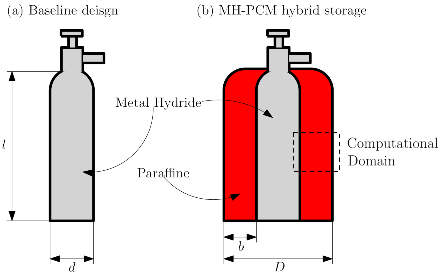
3. Hybrid Metal Hydride PCM-TES Design

We consider the off-the-shelf canister MyH2-2000 produced by H2Planet [27], whose relevant properties are reported in Table 1, as the starting point to design the hybrid MH–PCM storage system (see Figure 1a).
To model the heat generated by the H 2 absorption process, or equivalently required by its desorption, we select from [15] an AB 2 type alloy that has an equilibrium pressure in the range reported in Table 1.
Specifically, such an alloy is characterized by Δ h mh = 14 × 10 3 J/mol and by an entropy variation Δ s mh = 64 J/(molK), resulting in an equilibrium pressure of 12 bar at a temperature of 323 K (see Equation (1) [15] where p 0 = 1.0 bar is the reference pressure, T is the temperature, and R u = 8314 J/(kmolK) is the universal gas constant).
ln p p 0 = Δ h mh R u T Δ s mh R u .
The H 2 gravimetric density of the storage is w % , H 2 = M H 2 / M mh = 1.17 % where M H 2 and M mh are the masses of the H 2 and of the canister, respectively. A complete absorption cycle releases a quantity Q = M H 2 Δ h mh / M = 1155 kJ , of heat, where M = 2 g/mol is the molecular weight of H 2 . Equivalently, 58 W of thermal power must be drained from the canister surface to allow an H 2 flux of 1 kW while keeping its temperature constant. The same power should be provided during the desorption phase.
The heat exchange process at the canister surface is summarized by the Nusselt Number, Nu = λ l / k [34], where λ , is the convection coefficient, l is the reference length, and k is the thermal conductivity of the surrounding fluid.
For the baseline design, we proxy the canister with a vertical cylinder immersed in quiescent air. Thus, k = 0.256 W/(mK), l = 0.54 m is the height of the canister and, for natural convection [34]:
Ra = g β ( T T env ) l 3 ν 2 Pr Nu = 0.555 Ra 1 / 4 for Ra 10 9 Nu = 0.0210 Ra 2 / 5 for Ra > 10 9
where Ra is the Rayleigh number, g = 9.81 m/s 2 the magnitude of the gravitational acceleration, β , is the volumetric expansion coefficient, T env = 293 K is the temperature of the surrounding fluid, ν = 1.50 × 10 5 m 2 /s its kinematic viscosity, and Pr = 0.71 the Prandtl Number. We schematized the canister as a lumped parameter system with constant temperature at the outer wall, T = 323 K. Table 2a summarizes the resulting mail physical parameters relative to the heat exchange at the canister surface. Specifically, the thermal power exchanged at the surface of the baseline canister is limited to Q ˙ surf = 22 W. In turn, the H 2 mass flow is limited to 3.17 × 10 6 kg/s (see Equation (3)) that are equivalent to a storage power of W ˙ = m ˙ H 2 LHV H 2 = 308 W, where LHV H 2 is the Lower Heating Value of hydrogen.
m ˙ H 2 = Q ˙ surf Δ h mh M H 2 .
In such conditions, about 14 h are required to completely fill or unload the reservoir.
We finally evaluate that the Biot number, Bi = λ k mh / l * , where l * is a reference length equal to the ratio between the canister volume and the heat-exchanging surface. According to [34], the conductive resistance can be discarded, and the solid can be assumed at constant temperature for Bi < 0.1 : for the baseline design, Bi < 0.1 if k mh > 1 W/(mK). Enhanced configurations have higher conductivity [15,30,31,32] but k mh 1 W/(mK) is also feasible for pure MH canisters [28,29]. In the following, the lumped parameter hypothesis holds, and λ is effectively limiting the input/output power of the storage.
To increase the heat exchanged at the surface, we improve the design of the baseline storage by flooding the canister within a PCM thermostatic bath (see Figure 1b). As PCM, we consider the paraffin octadecane, whose relevant thermo-chemical properties are reported in Table 2b.
Table 2. Summary of the relevant heat exchange parameters for (a) baseline design; (b) MH–PCM integrated system.
(a) Baseline Design
k 2.56 × 10 2 W/(mK)[34]
ν 1.50 × 10 5 m 2 /s 2 [34]
β 3.41 × 10 3 1/K[34]
ρ 1.19 kg/m 3 [34]
Ra 5.15 × 10 8 —–Equation (2)
Nu 8.36 × 10 1 —–Equation (2)
Pr 0.71 —–[34]
T env 293K
λ 3.93 W/(m 2 K)
Q ˙ surf 22W
(b) MH–PCM integrated system
k 1.52 × 10 1 W/(mK)[35]
ν 4.50 × 10 6 m 2 /s 2 [35]
β 9.10 × 10 4 1/K[35]
ρ 800kg/m 3 [35]
Ra 8.90 × 10 10 —–Equation (2)
Nu188—–Equation (5)
Pr60—–[35]
T env 302K[35]
λ 53W/(m 2 K)
Q ˙ surf 208W
In the following, we focus on the melting process. Heat transfer mechanisms at the solid wall follow three regimes, namely pure conduction, mixed conduction/convection, and pure convection. In two dimensions, we proxy the whole system as a rectangular cavity with one hot wall (at the inner) and a cold wall (at the outer, see Figure 1b). For this geometry, the different heat transfer regimes can be summarized through Equaton (4) [36]:
Nu = ( 2 θ ) 1 / 2 + c 1 Ra 1 / 4 2 θ 1 / 2 1 + c 2 Ra 3 / 4 θ 3 / 2 n 1 / n ,
where θ = Fo St is the non-dimensional time, St = C ( T T env ) / L is the Stefan and Fo = α t / l 2 the Fourier numbers, respectively, and c 1 , c 2 , and n are empirical parameters to be evaluated according to the melting regime. Before the upper boundary of the domain is completely melted c 1 = 0.35 , c 2 = 0.0175 , and n = 2 [36].
For the convective regime, Equation (4) asymptotically approaches Nu calculated through Equation (5) (see Figure 2).
Nu = 0.35 Ra 1 / 4 [ 1 + ( 0.143 / Pr ) 9 / 16 ] 4 / 9 .
For the MH–PCM hybrid system Ra = 8.90 × 10 10 (see Table 2b) and Nu > Nu for θ > 10 4 (see Figure 2). Such a threshold corresponds to t > 0.2 s, which is much lower compared to the expected time to load the canister. Thus, we can safely assume that Nu = Nu for the whole process.
The results summarized in Table 2b highlight that the PCM significantly enhances Nu , λ and, in turn, Q ˙ surf . The thermal power exchanged at the surface is about 10 times larger compared to the baseline design. This increment would allow an H 2 mass flow of m ˙ H 2 = 2.97 × 10 5 kg/s, corresponding to W ˙ = 3565 W. With such a mass flow, the canister is completely charged/discharged in about 1.5 h.
However, we wish to emphasize that, in this case, Bi < 0.1 only for k mh > 15 W/mK, which is feasible only for advanced canister design with enhanced inner thermal conductivity [15,30,31,32]. For pure MH alloys Bi > 0.1 , the lumped parameter hypothesis is not strictly valid, and thermal conduction inside the canister might also limit the storage power.
The total heat released during the charge process is Q = m H 2 Δ h mh = 1155 kJ. The amount of PCM required to store such thermal energy is m PCM = Q / L = 4.73 kg, corresponding to a volume of V PMC = 5.92 × 10 3 m 3 that can be obtained through a jacket with external diameter D = 0.16 m (see Figure 1).
The results reported in Table 2 provide evidence of the feasibility of the hybrid energy storage concept. However, more thorough analysis of the heat exchange processes at the canister surface is required for the design of a working prototype, especially to evaluate the system performance during transient operation.
To this aim, in Section 4, we propose a novel, accurate, and fast method to predict the local values of Ra and Nu , in order to convey more thorough information for the design of heat-recovery systems for metal-hydride-based H 2 storage solutions. Specifically, leveraging the unsteady nature of the Lattice Boltzmann Method (LBM) and its mesoscopic foundations, we propose a multi-dimensional method to track the evolution of PCM melting and solidification, accounting for the energy storage and release, as a function of Nu in the different regimes of the phase change [36].

4. Multidimensional Modeling of PCM Melting & Solidification

We adopt a standard 2-population LB implementation [18,37,38] within the Lattice Boltzmann Method (LBM) to solve the fluid dynamics and the thermal evolution:
f i ( x + c i , t + 1 ) f i ( x , t ) = 1 τ F f i e q ( x , t ) f i ( x , t ) + F B + F D r a g
g i ( x + c i , t + 1 ) g i ( x , t ) = 1 τ T g i e q ( x , t ) g i ( x , t ) + F L
In the above, we have τ F the (standard) fluid relaxation time, given by τ F = ν c s 2 + 1 2 (with ν the kinematic viscosity); τ T the thermal relaxation time, provided by τ T = α c s 2 + 1 2 , with α representing the thermal diffusivity.
Equation (6) accounts for the fluid dynamic evolution of the fluid, while Equation (7) is responsible for the thermal evolution. With this approach, the temperature is treated as a passive scalar, whose effects are felt by the fluid according to ad-hoc tuned forces (i.e., buoyancy effects).
The three forcing terms at the rhs of Equations (6) and (7) represent, respectively: F B the buoyancy effect; F D r a g the fluid–solid interaction, given by an empirical mesoscopic drag, which enforces no-flow inside the solid region [39]; finally, F L stands for the latent heat release/absorption during melting/solidification phenomena, respectively.
To compute these forces, one has to evaluate the evolution in time of the phase field ϕ that governs the melting/solidification front. More specifically, we have the following rate equation, in the discretized approach:
ϕ ( x , t ) = ϕ ( x , t 1 ) + R ,
in which, R is the reaction term expressed as in [39],
R ( x , t ) = f + K + ( x , t ) [ 1 ϕ ( x , t 1 ) ] f K ( x , t ) [ 1 + ϕ ( x , t 1 ) ] ,
in which f+ and f are frequency factors (basically, the inverse time scale for melting and solidification, respectively) and K + and K are switch functions controlling the onset of melting and solidification, respectively, around a critical temperature T c r .
Here, we directly adopt the modified switches proposed in [39], given by
K + ( x , t ) = 1 2 1 + tanh T ( x , t ) T c r T s T w × 1 8 i 1 2 [ 1 + ϕ ( x + c i ) , t ) ] 2
K ( x , t ) = 1 2 1 tanh T ( x , t ) T c r + T s T w × 1 8 i 1 2 [ 1 ϕ ( x + c i ) , t ) ] 2
In the above, T w controls the energy range of the transition and T s provides two different activation energies for melting and solidification. In our basic test cases, T s = 0 .
From the evolution in time of ϕ , we find the three force contributions in Equations (6) and (7):
| F B | = β T ( x , t ) 1 + ϕ ( x , t ) 2
F D r a g = ϖ u ( x , t ) 1 ϕ ( x , t )
F L = Δ T St Δ ϕ
In the above, we have
  • ϖ is a relaxation parameter, chosen to be in the order of 0.5, to ensure that the relaxation of F D r a g is faster than the other dynamics;
  • St is the non-dimensional Stefan number, given by St = c T l i q T s o l L , with c the specific heat and L the latent heat.
  • Δ T is the characteristic temperature difference: we have fixed Δ T = T l i q T s o l ;

5. Numerical Results & Discussion

In the following, we first validate the proposed numerical method against the classicl 1D Stefan Problem, in which the buoyancy effects are neglected. Then, we focus on a 2D layout, enabling the effects of gravity and buoyancy and validate our code against results acquired from the literature.

5.1. 1D Stefan Problem

We take as benchmark the results in [40], considering three values for thermal diffusivity, α = 0.033 , 0.36 and 0.70 in lattice units. To reproduce these results, we have considered the very same Stefan number as in [40], St = 1 : fixing T s o l = 273.0 K, we have T l i q = 352.5 K.
The domain is a 100 × 5 , 2D box, as in [40]. Fist, we investigate the type of boundary conditions that must be implemented to accurately capture the evolution of the 1D melting problem. In our double-population approach, we have to dissect the nature of the boundary conditions according to the population we are considering: from the hydrodynamic point of view (i.e., for the f population in Equation (6)), our computational domain is a closed box with wall-no slip conditions on all boundaries. For what concerns population g in Equation (7), that is, for the thermal evolution of our system, we have a different picture: the left boundary (West) is the heated side, thus it has a constant temperature, higher than that of the solid PCM; the right boundary (East) has a fixed temperature, equal to that of the solid PCM; the top and bottom sides of the domain (the North and South) are schematized as adiabatic walls.
To implement such adiabatic conditions, at least two methods can be retrieved from the literature [37,41]: a (thermal) free-slip wall and an equilibrium condition. While the first one can be immediately recognized as a strightforward adiabatic condition, the second one can provide accurate results, provided that the thermal gradients (both in time and space) are small compared to the characteristic space and time scales of the problem under investigation [41].
The results of the 1D simulation for the two described boundary conditions are reported in Figure 3, which shows the comparison with the results reported in [40]: Figure 3a reports the results obtained with the free-slip boundary condition (bc) is set at the North and South walls, while in Figure 3b, the results with an equilibrium condition at the top and bottom boundaries are shown.
Figure 3 highlights that no appreciable differences emerge when implementing equilibrium or free-slip bc’s in the 1D cases, due to the absence of gravity and buoyancy.

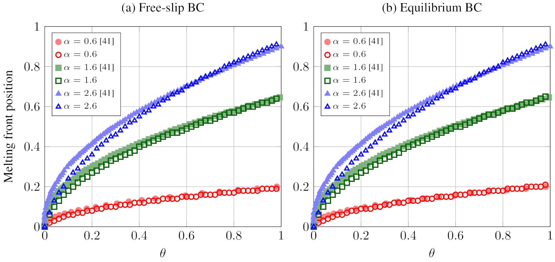
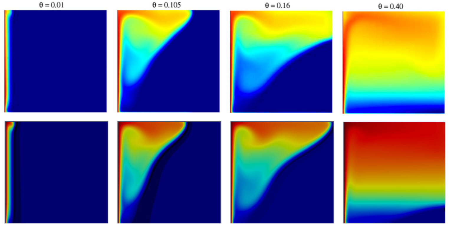
5.2. 2D Melting: The Effects of Gravity and Buoyancy

In this Section, we consider a square cavity filled with solid PCM. As in the previous simulations, the left wall is heated (i.e., it is at constant temperature T w a l l = T l i q ), the solid is kept at T s o l = T m e l t . Our 2D computational domain reproduces the portion of the PCM jacket represented by the dotted rectangle in Figure 1b: the left wall is the heated side, due to the exothermic reaction of H 2 absorption within the hydride; the right wall is schematized at constant temperature and the top and bottom sides are assumed as adiabatic. Considering a small portion of the entire canister allows us to spare considerable CPU time, but the local Ra and Nu numbers will be lower than those of the case analyzed in the previous sections. However, such values will be compliant to those of the benchmark cases reported in [40,42].
Figure 4 reports the evolution in time of the Nu number computed at the heated wall, as a function of the Ra number. The figure highlights that our model is capable of following the transient evolution in Nu , due to the different regimes associated with the melting of the soldi PCM [36,42]: first, a conduction-dominated phase, with a sudden drop in the Nu number; then, Nu re-increases and reaches a plateau in the conduction-dominated phase; finally, a progressive reduction in Nu , that starts when the melted front reaches the right (cold) wall. Moreover, compared to the numerical benchmarks proposed in [40], our model provides values of the Nu numbers in the plateau region that are closer to the predictions provided by the equations developed in [42].
Figure 5, the evolution of the temperature field in time in our computational domain, compared to the contours provided in [40]: the panel highlights the good matching between our results and those in [40] for the same Pr, Ra and St numbers.
Figure 5 highlights the very good matching between our results and those provided in [40]. The time evolution of the interface between solid and liquid paraffin, in fact, follows the very same steps in the two models, at Ra = 6.8 × 10 6 :
  • θ 0.01 
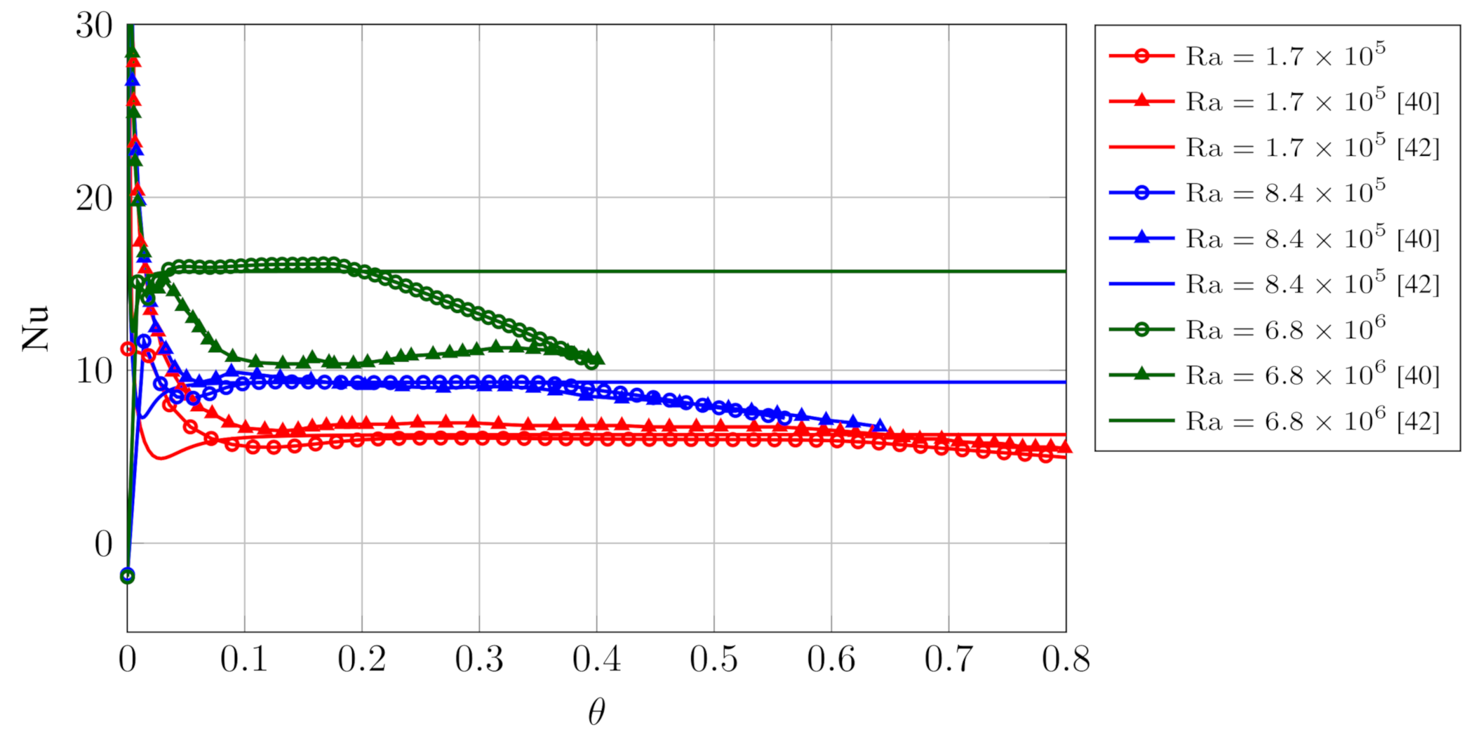
: the end of the conduction-dominated phase, with the formation of a rounded sack on top of the computational domain, due to the inception of convective motions;
  • θ > 0.05 : advance of the interface towards the cold wall, with the formation of a rounded profile in the upper part of the computational domain, due to the melting front pointing downwards;
  • θ > 0.15 
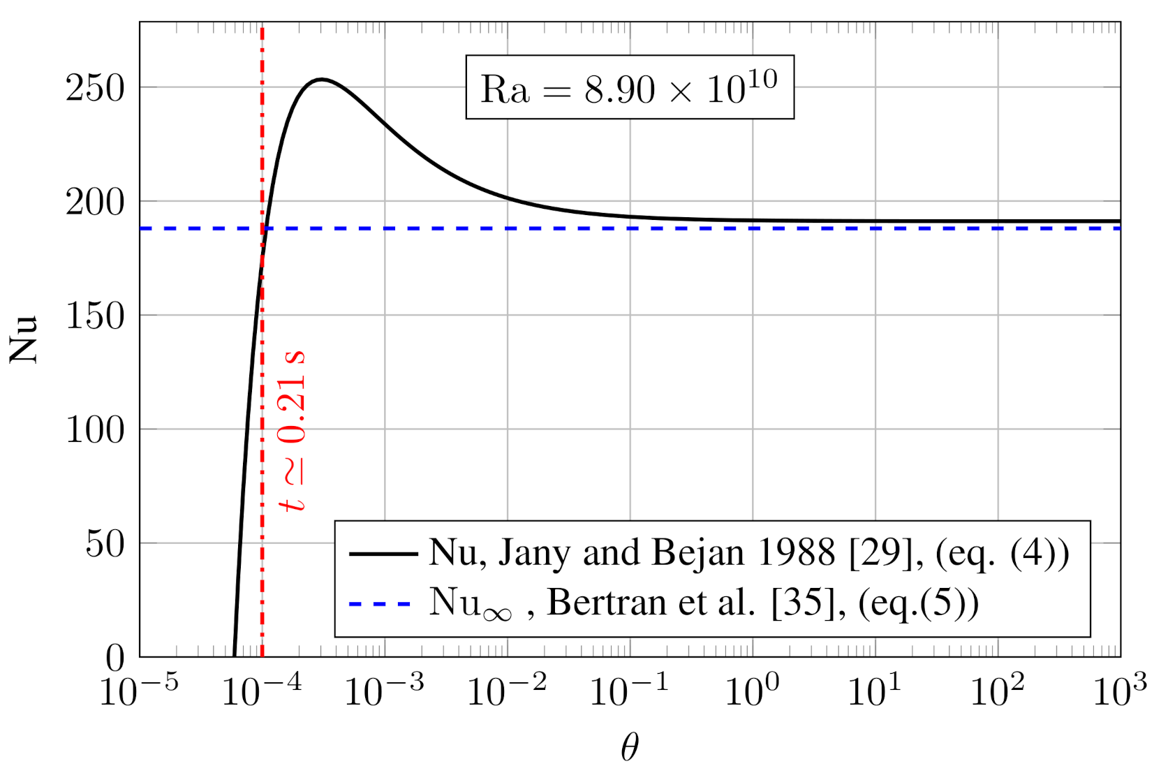
: the melting front reaches the cold wall: this corresponds to the end of the plateau region of Nu in Figure 4;
  • θ > 0.2 : the progressive shrinkage of the solid phase.

6. Conclusions

Hydrogen storage solutions will play a pivotal role, in the coming years, in implementing a reliable and cost-effective “ Hydrogen Economy”. In this framework, metal hydrides have proven to have a remarkable potential in delivering safe and reliable H 2 storage systems. In this paper, we have provided novel, promising results for the implementation of metal hydride H 2 storages, by coupling them with a PCM-based thermal energy storage. More specifically, we have designed an engineering solution to store the heat released by the hydrides during the H 2 loading process by means of a Phase Change Material (PCM). Specifically, preliminary design results demonstrate the high potential of the proposed solution in terms of increased power density. In fact, the PCM allows for better control of the MH temperature, and, in turn equilibrium pressure. Moreover, we provide evidence that such a solution would have a negligible impact on the system cost, mass, and volume. However, in order to reach a more accurate system design capable to address the local (transient) heat transfer phenomena during the melting/solidification phases, we have developed an innovative LBM implementation to assist the engineering design of optimized PCM–MH storage systems.
More specifically, to account for the local evolution in time of the Nu number, we have developed a fast and reliable 2D algorithm to track the melting of the paraffine-like material chosen as PCM. Results reported in Section 5 demonstrate the the proposed methodology The model provides an accurate and reliable description of the melting phenomenon, compared to the results provided in the literature.
Further developments hinge on the promising results evidenced both by the innovative numerical LBM implementation and by its application to the MH–PCH hybrid system. Specifically, further work should be conducted to account for density variations within the proposed numerical framework. Similarly, the proposed methodology will be used to numerically model MH–PCM system.

Author Contributions

Investigation, A.L.F., G.F. and V.V.; Methodology, G.F., A.L.F. and M.L.; Project administration, G.F.; Supervision, S.S. All authors have contributed in interpreting the results and in writing the paper and agreed to the published version of the manuscript.

Funding

This research received financial support from the European Research Council under the Horizon 2020 Programme Advanced Grant Agreement n. 739964 (“COPMAT”), the PRIN Project CUP E84I19001020006, and PRIN Project 2017F4S2L3.

Institutional Review Board Statement

Not applicable.

Informed Consent Statement

Not applicable.

Data Availability Statement

Data are available upon request to [email protected].

Acknowledgments

S.S. and M.L. wish to acknowledge financial support from the European Research Council under the Horizon 2020 Programme Advanced Grant Agreement n. 739964 (“COPMAT”). G.F wishes to acknowledge the support of PRIN Project CUP E84I19001020006, with Gino Bella as the Scientific Responsible. The present research work has received funding from the Italian Ministry of Education, Universities and Research, MIUR, as Project of National Interest, PRIN 2017F4S2L3.

Conflicts of Interest

The authors declare no conflict of interest.

Nomenclature

Physical Parameters
C Specific heat of the liquid phase (melting process)J/(kgK)
c 1 , c 2 , n Empirical constants for Nu evaluation
c i Lattice discretized directions
F B , F D r a g , F L Force terms in the LB Equations (6) and (7)
DDiameterm
Δ h mh Enthalpy variation for MH absorption/desorptionJ/mol
Δ s mh Entropy variation for MH absorption/desorptionJ/(molK)
f i ( x , t ) Lattice populations for fluid flow
f+, fFrequency factors for melting/solidification
g             Gravitational accelerationm/s
gmagnitude of the gravitational accelerationm/s
g i ( x , t ) Lattice populations for temperature evolution
H             Height of the computational domainm
K + ( x , t ) , K ( x , t ) Switch functions for (local) melting/solidification
kHeat conduction coefficientW/(mK)
k mh MH heat conduction coefficientW/(mK)
l , l * Reference lengthm
L Latent heat of fusionJ/kg
LHV H 2 Hydrogen Lower Heating ValueJ/kg or J/mol
M Molecular weightg/mol
M H 2 Mass of the H 2 stored in the MHkg
M mh Metal hydride masskg
M PCM PCM masskg
pPressurebar
p 0 Reference pressurebar
QThermal energyJ
Q ˙ surf Thermal power exchanged at the canister surfaceW
R Reaction term for liquid/solid phase change
R u Universal gas constantJ/(molK)
TTemperatureK
tTimes
T c r Critical temperature (melting/solidification)K
T env Environment reference temperatureK
T l i q Temperature of the wallK
T l i q Temperature of the liquid phaseK
T s Melting/solidification activation energyK
T w Control parameter for phase transition interface widthK
T s o l Temperature of the solid phaseK
V PCM PCM volumem 3
w % , H 2 Gravimetric density of MH storage%
W ˙ Storage powerW
Greek Letters
α Thermal diffusivitym 2 /s
β Coefficient of thermal volumetric expansion1/K
λ Thermal convection coefficientW/m 2
ν Kinematic viscositym 2 /s
ϕ phase field variable for solid/liquid evolution
θ Dimensionless time
θ * Time when the top wall is fully bathed by liquid
τ F Fluid relaxation time
τ T Thermal relaxation time
ϖ Frequency factor for the drag force F D r a g
Acronyms
1DOne Dimensional
2DTwo Dimensional
BiBiot number
CHPCombined Heat and Power
FoFourier number
LBMLattice Boltzmann Method
MHMetal Hydride
NuNusselt number
PCMPhase Change Material
PrPrandtl number
RaRayleigh number
StStefan number
TESThermal energy Storage

References

  1. Boyle, G. Renewable Energy: Power for a Sustainable Future; Oxford University Press: Oxford, UK, 2004. [Google Scholar]
  2. Facci, A.L.; Krastev, V.K.; Falcucci, G.; Ubertini, S. Smart integration of photovoltaic production, heat pump and thermal energy storage in residential applications. Sol. Energy 2019, 192, 133–143. [Google Scholar] [CrossRef]
  3. Ubertini, S.; Facci, A.L.; Andreassi, L. Hybrid hydrogen and mechanical distributed energy storage. Energies 2017, 10, 2035. [Google Scholar]
  4. Chiappini, D.; Facci, A.L.; Tribioli, L.; Ubertini, S. SOFC management in distributed energy systems. J. Fuel Cell Sci. Technol. 2011, 8, 031015. [Google Scholar]
  5. Facci, A.L.; Sánchez, D.; Jannelli, E.; Ubertini, S. Trigenerative micro compressed air energy storage: Concept and thermodynamic assessment. Appl. Energy 2015, 158, 243–254. [Google Scholar]
  6. Facci, A.L.; Cigolotti, V.; Jannelli, E.; Ubertini, S. Technical and economic assessment of a SOFC-based energy system for combined cooling, heating and power. Appl. Energy 2017, 192, 563–574. [Google Scholar]
  7. Facci, A.L.; Loreti, G.; Ubertini, S.; Barbir, F.; Chalkidis, T.; Eßling, R.P.; Peters, T.; Skoufa, E.; Bove, R. Numerical assessment of an automotive derivative CHP fuel cell system. Energy Procedia 2017, 105, 1564–1569. [Google Scholar]
  8. Facci, A.L.; Ubertini, S. Analysis of a fuel cell combined heat and power plant under realistic smart management scenarios. Appl. Energy 2018, 216, 60–72. [Google Scholar]
  9. Loreti, G.; Facci, A.L.; Peters, T.; Ubertini, S. Numerical modeling of an automotive derivative polymer electrolyte membrane fuel cell cogeneration system with selective membranes. Int. J. Hydrog. Energy 2019, 44, 4508–4523. [Google Scholar]
  10. Loreti, G.; Facci, A.L.; Baffo, I.; Ubertini, S. Combined heat, cooling, and power systems based on half effect absorption chillers and polymer electrolyte membrane fuel cells. Appl. Energy 2019, 235, 747–760. [Google Scholar]
  11. Abe, J.O.; Popoola, A.; Ajenifuja, E.; Popoola, O. Hydrogen energy, economy and storage: Review and recommendation. Int. J. Hydrog. Energy 2019, 44, 15072–15086. [Google Scholar]
  12. Minutillo, M.; Forcina, A.; Jannelli, N.; Lavadera, A.L. Assessment of a sustainable energy chain designed for promoting the hydrogen mobility by means of fuel-cell powered bicycles. Energy 2018, 153, 200–210. [Google Scholar]
  13. Andreassi, L.; Falcucci, G.; Facci, A.L.; Ubertini, S. Environmental and Health Impact of Electric and Hydrogen Light Vehicles: The Case of an Italian Small City; SAE Technical Paper; SAE International: Warrendale, PA, USA, 2019. [Google Scholar] [CrossRef]
  14. Hirscher, M.; Yartys, V.A.; Baricco, M.; von Colbe, J.B.; Blanchard, D.; Bowman, R.C., Jr.; Broom, D.P.; Buckley, C.E.; Chang, F.; Chen, P.; et al. Materials for hydrogen-based energy storage–past, recent progress and future outlook. J. Alloy Compd. 2020, 827, 153548. [Google Scholar]
  15. Lototskyy, M.; Sekhar, B.S.; Muthukumar, P.; Linkov, V.; Pollet, B. Niche applications of metal hydrides and related thermal management issues. J. Alloy Compd. 2015, 645, S117–S122. [Google Scholar]
  16. Afzal, M.; Mane, R.; Sharma, P. Heat transfer techniques in metal hydride hydrogen storage: A review. Int. J. Hydrog. Energy 2017, 42, 30661–30682. [Google Scholar]
  17. Shafiee, S.; McCay, M.H. Different reactor and heat exchanger configurations for metal hydride hydrogen storage systems—A review. Int. J. Hydrog. Energy 2016, 41, 9462–9470. [Google Scholar]
  18. Succi, S. The Lattice Boltzmann Equation for Fluid Dynamics and Beyond; Clarendon: Oxford, UK, 2001. [Google Scholar]
  19. Montessori, A.; La Rocca, M.; Falcucci, G.; Succi, S. Regularized lattice BGK versus highly accurate spectral methods for cavity flow simulations. Int. J. Mod. Phys. C 2014, 25, 1441003. [Google Scholar]
  20. Falcucci, G.; Amati, G.; Krastev, V.K.; Montessori, A.; Yablonsky, G.S.; Succi, S. Heterogeneous catalysis in pulsed-flow reactors with nanoporous gold hollow spheres. Chem. Eng. Sci. 2017, 166, 274–282. [Google Scholar]
  21. Krastev, V.; Falcucci, G. Simulating engineering flows through complex porous media via the lattice Boltzmann method. Energies 2018, 11, 715. [Google Scholar]
  22. Montessori, A.; Falcucci, G. Lattice Boltzmann Modeling of Complex Flows for Engineering Applications; Morgan & Claypool Publishers: Bristol, UK, 2018; pp. 2053–2571. [Google Scholar] [CrossRef]
  23. Succi, S.; Amati, G.; Bernaschi, M.; Falcucci, G.; Lauricella, M.; Montessori, A. Towards exascale lattice Boltzmann computing. Comput. Fluids 2019, 181, 107–115. [Google Scholar]
  24. Venturi, S.; Di Francesco, S.; Geier, M.; Manciola, P. A new collision operator for lattice Boltzmann shallow water model: A convergence and stability study. Adv. Water Resour. 2020, 135, 103474. [Google Scholar]
  25. Durbin, D.; Malardier-Jugroot, C. Review of hydrogen storage techniques for on board vehicle applications. Int. J. Hydrog. Energy 2013, 38, 14595–14617. [Google Scholar] [CrossRef]
  26. Rizzi, P.; Pinatel, E.; Luetto, C.; Florian, P.; Graizzaro, A.; Gagliano, S.; Baricco, M. Integration of a PEM fuel cell with a metal hydride tank for stationary applications. J. Alloy Compd. 2015, 645, S338–S342. [Google Scholar] [CrossRef]
  27. Planet, H. MyH2-2000 Technical Specifications. Available online: https://www.h2planet.eu/en/detail/MyH22000 (accessed on 26 November 2020).
  28. Zhao, W.; Yang, Y.; Bao, Z.; Yan, D.; Zhu, Z. Methods for measuring the effective thermal conductivity of metal hydride beds: A review. Int. J. Hydrog. Energy 2020, 45, 6680–6700. [Google Scholar] [CrossRef]
  29. Escobar, A.R.G. TiMn2 Based Metal Hydrides for Hydrogen Compression Applications: Numerical and Experimental Approach. Ph.D. Thesis, Univesidad Autonoma de Madrid, Madrid, Spain, 2018. [Google Scholar]
  30. Laurencelle, F.; Goyette, J. Simulation of heat transfer in a metal hydride reactor with aluminium foam. Int. J. Hydrog. Energy 2007, 32, 2957–2964. [Google Scholar] [CrossRef]
  31. Sánchez, A.R.; Klein, H.P.; Groll, M. Expanded graphite as heat transfer matrix in metal hydride beds. Int. J. Hydrog. Energy 2003, 28, 515–527. [Google Scholar]
  32. Ron, M.; Bershadsky, E.; Josephy, Y. Thermal conductivity of PMH compacts, measurements and evaluation. Int. J. Hydrog. Energy 1992, 17, 623–630. [Google Scholar]
  33. Davids, M.; Lototskyy, M.; Malinowski, M.; van Schalkwyk, D.; Parsons, A.; Pasupathi, S.; Swanepoel, D.; van Niekerk, T. Metal hydride hydrogen storage tank for light fuel cell vehicle. Int. J. Hydrog. Energy 2019, 44, 29263–29272. [Google Scholar]
  34. Kreith, F.; Manglik, R.M.; Bohn, M.S. Principles of Heat Transfer; Cengage Learning: Boston, MA, USA, 2012. [Google Scholar]
  35. Madruga, S.; Curbelo, J. Dynamic of plumes and scaling during the melting of a Phase Change Material heated from below. Int. J. Heat Mass Transf. 2018, 126, 206–220. [Google Scholar]
  36. Jany, P.; Bejan, A. Scaling theory of melting with natural convection in an enclosure. Int. J. Heat Mass Transf. 1988, 31, 1221–1235. [Google Scholar]
  37. Krüger, T.; Kusumaatmaja, H.; Kuzmin, A.; Shardt, O.; Silva, G.; Viggen, E.M. The Lattice Boltzmann Method; Springer: Berlin/Heidelberg, Germany, 2017; Chapter 8. [Google Scholar]
  38. Succi, S. The Lattice Boltzmann Equation: For Complex States of Flowing Matter; Oxford University Press: Oxford, UK, 2018. [Google Scholar]
  39. Miller, W.; Succi, S.; Mansutti, D. Lattice Boltzmann model for anisotropic liquid-solid phase transition. Phys. Rev. Lett. 2001, 86, 3578. [Google Scholar]
  40. Huber, C.; Parmigiani, A.; Chopard, B.; Manga, M.; Bachmann, O. Lattice Boltzmann model for melting with natural convection. Int. J. Heat Fluid Flow 2008, 29, 1469–1480. [Google Scholar]
  41. Di Ilio, G.; Ubertini, S.; Succi, S.; Falcucci, G. Nanofluid Heat Transfer in Wavy-Wall Channels with Different Geometries: A Finite-Volume Lattice Boltzmann Study. J. Sci. Comput. 2020, 83, 56. [Google Scholar]
  42. Bertrand, O.; Binet, B.; Combeau, H.; Couturier, S.; Delannoy, Y.; Gobin, D.; Lacroix, M.; Le Quéré, P.; Médale, M.; Mencinger, J.; et al. Melting driven by natural convection A comparison exercise: First results. Int. J. Therm. Sci. 1999, 38, 5–26. [Google Scholar]
Figure 1. Schematic representation of the considered canisters: (a) Baseline design of MyH 2 -2000; (b) hybrid MH–PCM storage system. The dotted rectangle sketches the computational domain adopted in Section 5.
Energies 14 01554 g001
Figure 2. Nu as a function of θ for the melting phase change material (PCM).
Energies 14 01554 g002
Figure 3. Position of the melting front according to three values of the thermal diffusivity α .
Energies 14 01554 g003
Figure 4. Comparison of Nu numbers for different values of Ra .
Energies 14 01554 g004
Figure 5. Temperature evolution in time θ for Pr = 1 , Ra = 6.8 × 10 6 and St = 10 ; top row=results from [40]; bottom row: results obtained with the proposed model. The comparison shows a good agreement between the numerical solutions obtained by the two different models.
Energies 14 01554 g005
Table 1. Relevant properties of the MyH2-2000 canister [27].
Volume of H 2 stored2Sm 3
Mass of H 2 stored 0.164 kg
Energy stored≃5.5kWh
Canister weight14kg
Canister volume 5.32 × 10 3 m 3
Canister diameter 0.11 m
Canister length 0.54 m
H 2 storage pressure10–12bar
Publisher’s Note: MDPI stays neutral with regard to jurisdictional claims in published maps and institutional affiliations.

