Article

Metaheuristic Based Solution for the Non‐Linear Controller of the Multiterminal High‐Voltage Direct Current Networks

1
College of Electrical Engineering, Guangxi University, Nanning 530004, China
2
College of Mechanical and Electrical Engineering and Quality Technology, Nanning University, Nanning 530200, China
3
School of Electrical Engineering, Xi’an Jiaotong University, Xi’an 710049, China
*
Author to whom correspondence should be addressed.
Energies 2021, 14(6), 1578; https://doi.org/10.3390/en14061578
Submission received: 5 February 2021 / Revised: 2 March 2021 / Accepted: 8 March 2021 / Published: 12 March 2021

Abstract

:
The purpose of this study is to improve the P-I controllers of the voltage-source converters (VSC)-based multiterminal high voltage direct-current (MT-HVDC) networks. Since the VSCs are the non-linear elements of the MT-HVDC stations, the classical optimization methods, which approximately implement the linear model to optimize the P-I controllers of the VSCs, do not generate optimal results. Therefore, this paper presents a novel technique to optimize the VSC-based MT-HVDC grids’ P-I controllers by embedding the artificial bee colony (ABC) algorithm. The voltage-droop control method is employed at on-shore grids to ensure the active and reactive power balance within MT-HVDC networks. During an evaluation, achieved via a detailed four-terminal MT-HVDC model designed in PSCAD/EMTDC, the improved results obtained under different dynamic situations such as unbalance wind power generation, change in load demand at the on-shore side grids, and eventual VSC disconnection, respectively.

1. Introduction

A recent study exhibits that a multiterminal high-voltage direct current (MT-HVDC) network is a realistic approach to fulfill future power system requirements. It is not only feasible technology for integrating large off-shore wind farms to the main AC grids [1], but also a possible approach to inter-link conventional AC girds to form a vast and wide-area power system.
The important components of the MT-HVDC are the voltage-source converters (VSC). Therefore, efficiently controlling the VSC is already discussed in many articles, such as [2,3,4,5,6,7]. The controlling mechanism of the VSC-based MT-HVDC grid utilizes the vector-current control (VCC) technique. The mechanism consists of two control loops; one is an inner-current control loop (ICC-L), and the seconds one is an outer-current control loop (OCC-L) [8,9]. The OCC-L role is to generate the ICC-L’s reference values (i.e., based on the linked AC-grids requirement) via active-power, reactive-power control, or DC, AC voltage regulation-based controllers, respectively. Whereas, ICC-L regulates d-q axis current values to VSCs, using the decoupling control strategy in the VSC-based HVDC system controlling mechanism. In this mechanism, the inner controller and outer controller have one common significant component: the proportional-integral (P-I) controller.
The voltage-droop regulation method is usually applied in the OCC-L and aims to control the DC-voltage within the specified range and regulate the power-sharing between the VSC-based HVDC stations [1,10,11]. The investigation of the MT-HVDC network’s inter-connecting control layers reveals that the VSC-based HVDC stations are complex multi-IP and multi-OP control systems [12]. As a complex controller, there are many variables, such as tuned P-I controllers, which require robust yet simple solutions [1,13,14]. Hence, relevant P-I parameters must be properly tuned and modified, which helps to improve the transient and steady-state response. However, conventional tuning approaches face complexities in optimizing the P-I parameters’ gain as they use approximate linear models to tune the gain of the P-I parameters [15,16].
Furthermore, it is challenging for the VSC controller’s non-linear nature to tune the P-I parameters’ gain and generate optimal results [17,18]. Despite its non-linear nature, VSC controllers give high efficiency over a wide operational range under dynamic conditions. Therefore, in the past decade, different computer-based intelligence methodologies were proposed to solve the non-linearities in the DC grids. However, the outcomes of some methodologies result in miss-convergence under dynamic conditions.
As a result, meta-heuristic models prove to be an excellent choice for dealing with non-linear systems. In [19] and [20], a well-known computerized methodology named genetic algorithm (G-A) is presented to enhance the system efficiency under dynamic operations by optimizing the controller’s gain. However, the G-A’s ability is limited as it shows a slower-convergence toward the solutions. It is hard to optimize the tune P-I controller’s parameters due to the solution’s slow convergence. Therefore, it requires an evolutionary meta-heuristic algorithm to address the deficiencies mentioned above.
In this paper, the multiobjective Artificial Bee Colony (ABC) technique is suggested and examined to optimize the VSC control structure. Besides, the multiterminal ABC technique has not been applied to enhance the VSC performance within an MT-HVDC network. PSCAD/EMTDC is used to design the four-terminal VSC-based MT-HVDC test model to conduct the dynamic simulation to evaluate the performance of the suggested optimization technique.
The optimized P-I controller’s parameters are obtained by implementing the multiobjective ABC, applied in the outer and inner control loops. Simulations conducted for classical P-I and ABC P-I are evaluated for dynamic and steady control performance under (i) unbalance wind power generation, (ii) unbalance power demand at the AC grid side, and (iii) eventual VSC disconnection.
The remainder of this paper is organized as follows. In Section 2, the mathematical modeling of all systems is presented. Section 3 represents the proposed optimization algorithm, whereas the execution of the multiobjective ABC algorithm is given in Section 4. Section 5 consists of simulation and results, and finally, conclusions are drawn in Section 6.

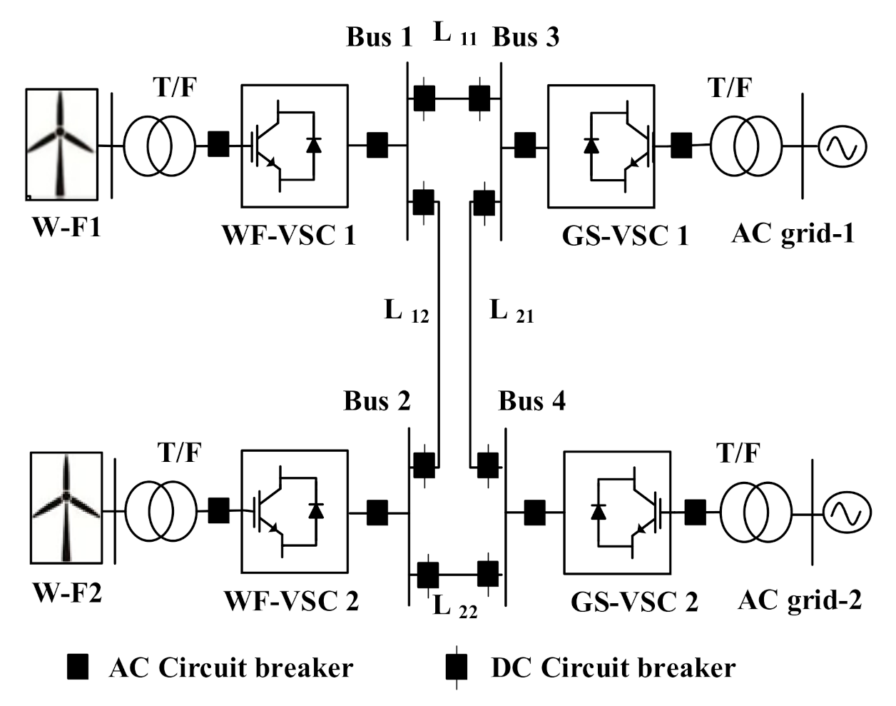
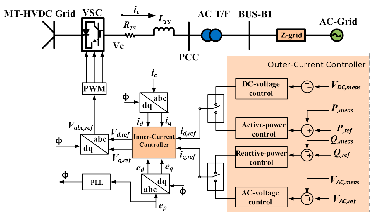
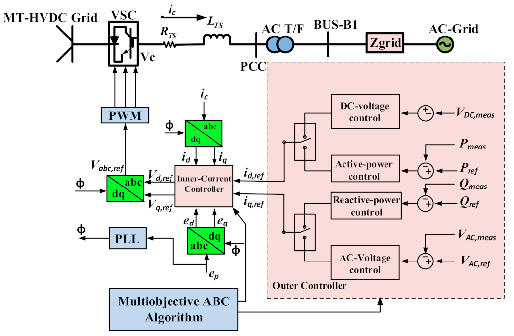
2. Control of Voltage-Source Converters (VSC) Based Multiterminal High Voltage Direct-Current (MT-HVDC) Grids

The four-terminal VSC-based HVDC grid is illustrated in Figure 1, where two on-shore AC grids interconnecting with two off-shore wind farms are recommended.
As shown in Figure 1, the VSC-based MT-HVDC grid includes wind power stations (W-F1 and W-F2), AC grids, VSCs, circuit-breakers, AC/transformers, AC filters, DC capacitors, DC link, and phase reactors. The controller framework regulates DC-voltage at the VSC station, reactive and active power regulation, plus AC voltage control at the point of common coupling (PCC). Usually, VCC is applied for voltage regulation in the MT-HVDC grid’s controller mechanism [21,22]. In this technique, the three-phase AC currents and voltages of the converter are converted into a dq reference frame (at PCC) using dq-axis transformation, meanwhile, synchronized to on-shore side grid AC voltages via phase-locked loop (PLL). This technique provides a simple and decoupled regulation of active-power and reactive-power, plus control of AC voltage and DC-voltage. The proposed structure of VCC at the VSC-based MT-HVDC terminal is shown in Figure 2. The OCC-L produces the ICC-L’s referenced currents, which then decides the referenced voltages for the VSC in the dq frame.

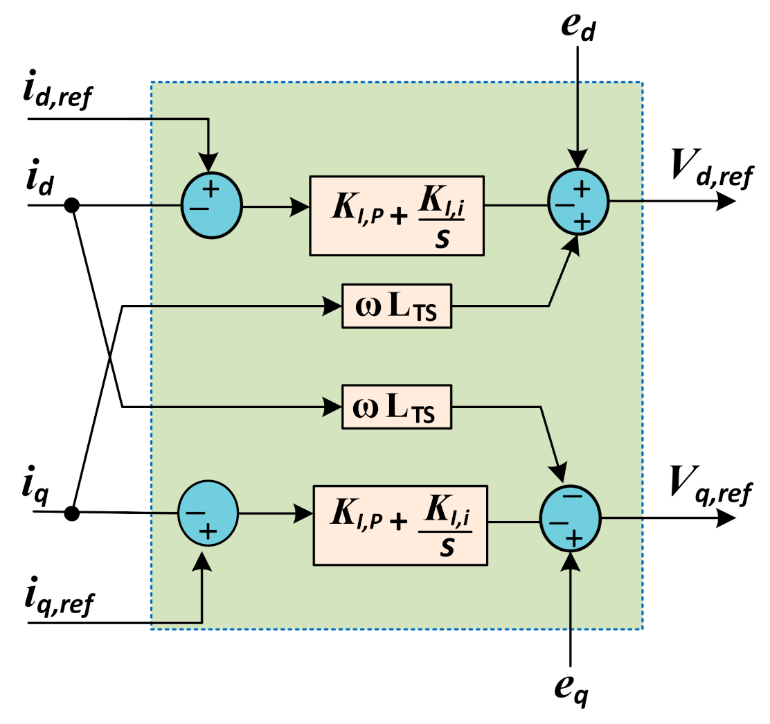
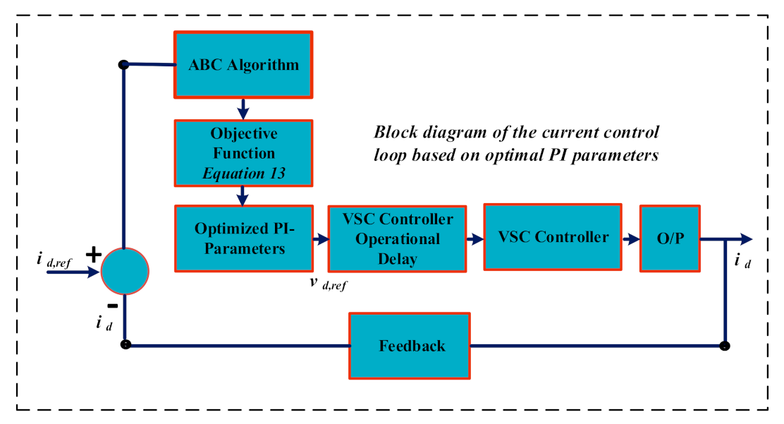
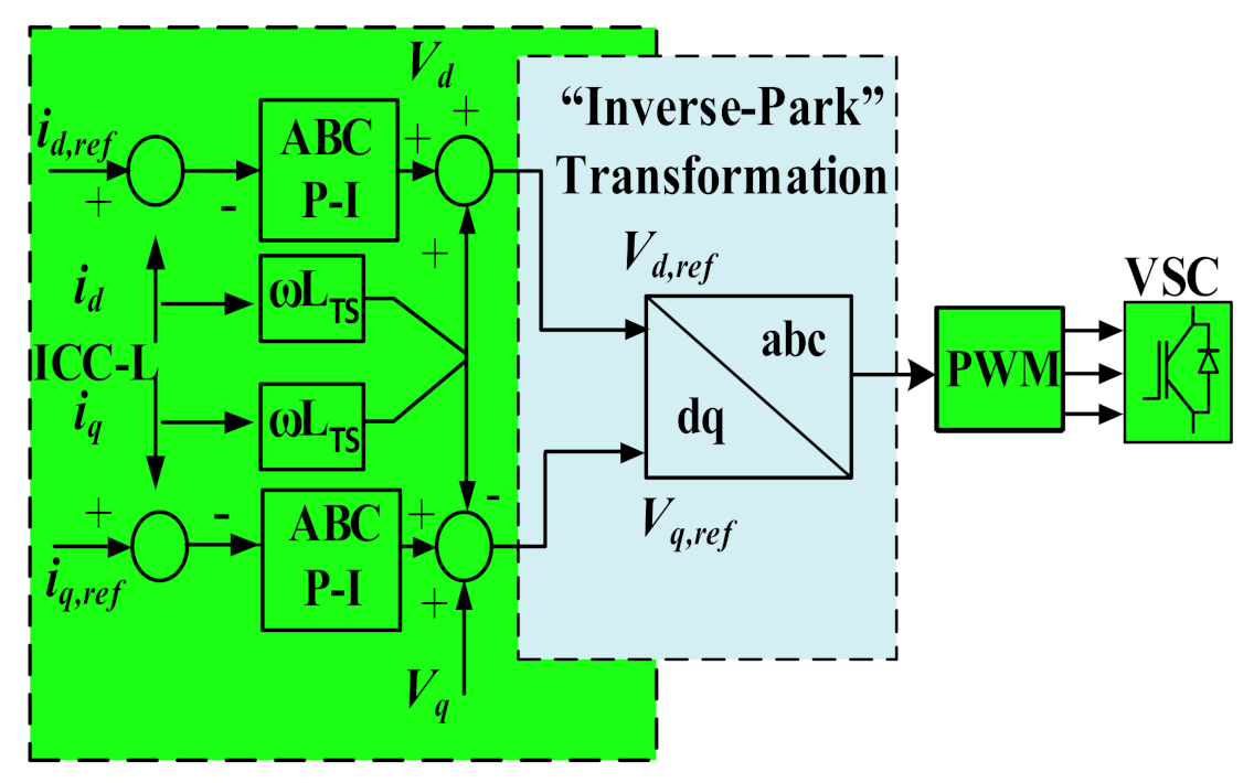
2.1. Inner Current Control Loop

Considering the dq-based VCC, the ICC-L incorporates fast P-I controllers responsible for the referenced currents produced by the OCC-L and generates the referenced voltages of the VSCs. The voltage difference at PCC ( e p ) and converter side ( v c ) is presented as:
e p v c = R T S × i c + L T S × d i c d t .
Here, e p shows the AC voltage of the transmission system at PCC and v c is the phase-voltage of the converter at the AC side. Whereas i c represents the AC system’s current to the VSC while, R T S and L T S are showing the resistance and inductance between the PCC and the VSC, respectively. After implementing the Park’s transformation [23]:
e d v d = R T S × i d ω L T S i q + L T S × d i d d t ,
e q v q = R T S × i q + ω L T S i d + L T S × d i q d t .
In Equations (2) and (3), e d shows the d-axis of the AC voltage of the transmission system and e q is the q-axis of the AC voltage of the transmission system. While v d indicates the d-axis component of the common bus voltage (p.u), v q shows the q-axis component of the common busy (p.u), ω represents the AC system’s angular frequency at the PCC. While i d is the current d-axis component at the AC side of the converter (p.u), and i q illustrates the q-axis component of the current flowing at the AC side of the converter (p.u). The ICC-L layout based on (2) and (3) is shown in Figure 3. Switching signals for IGBTs of the converter are produced by transforming the referenced voltages ( v d , r e f and v q , r e f ) into the ABC frame. v d , r e f and v q , r e f are voltage d-axis and q-axis components produced by the converter (p.u).

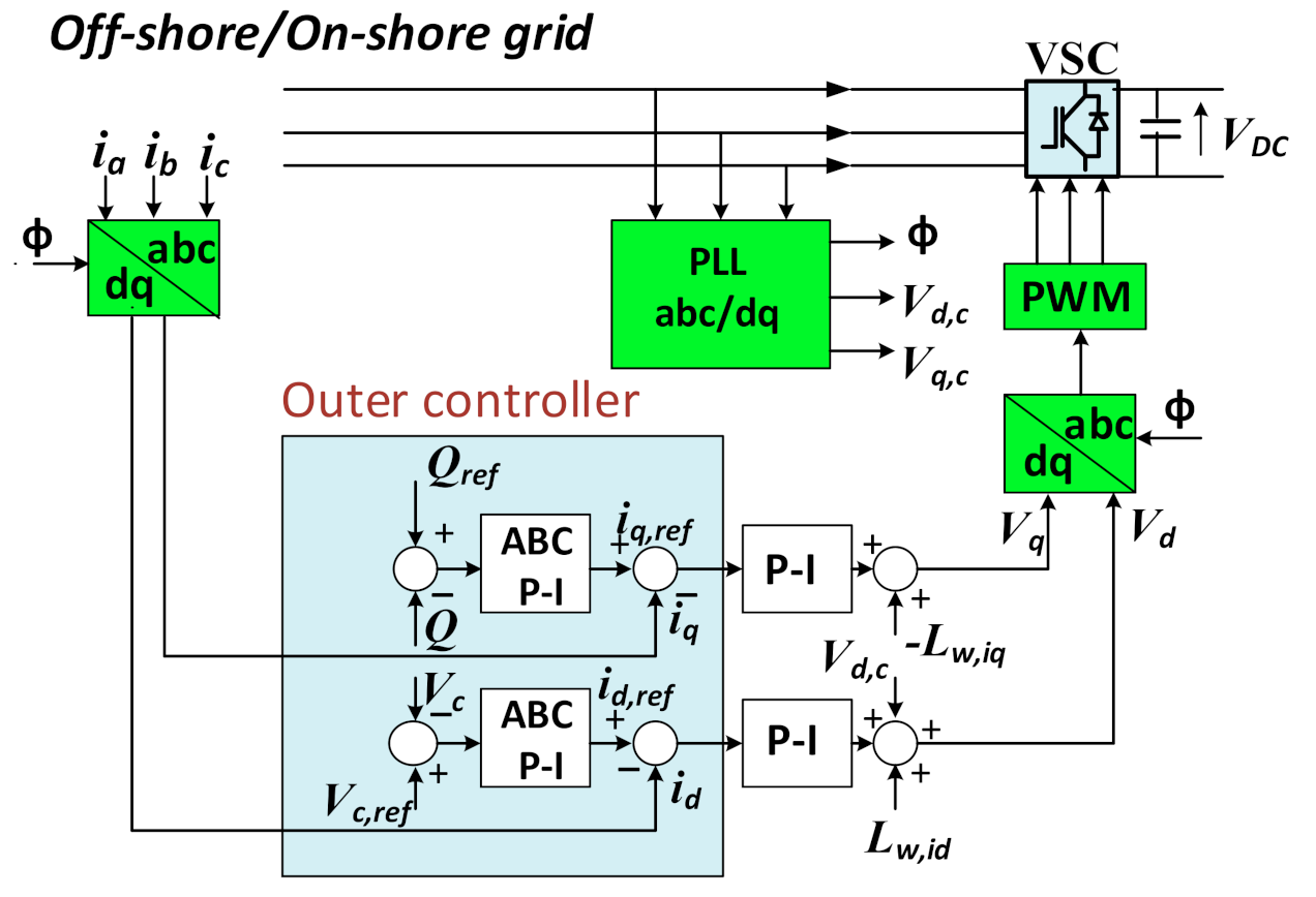
2.2. Outer Current Control Loop

The OCC-L regulates the AC and DC voltages, reactive and active-powers at the PCC. It includes the active and reactive channels, as illustrated in Figure 2. The active-channel controls DC voltage or active-power, and the reactive-channel controls the AC voltage or reactive power at the PCC and mathematically expressed as [24]:
P = v d i d + v q i q ,
Q = v q i d v d i q .
The d-axis of the dq-frame is synchronized to the AC network voltage-phasor via PLL; therefore, v q = 0:
P = v d i d ,
Q = v d i q .
The active-power and reactive-power are controlled using the dq-axis currents based on (6) and (7). The AC voltage regulator is designed to maintain the amplitude of the AC voltages at the PCC. Notably, it can be achieved by implanting an appropriate amount of reactive-power such that the AC voltage at the PCC meets the stated referenced value. Similarly, AC voltage can be controlled by adjusting the q-axis current. The active-power should be appropriately exchanged with the AC system to retain the DC-link voltages at its referenced value. Hence, the DC-link voltages can be regulated by adjusting the d-axis current ( i d ).

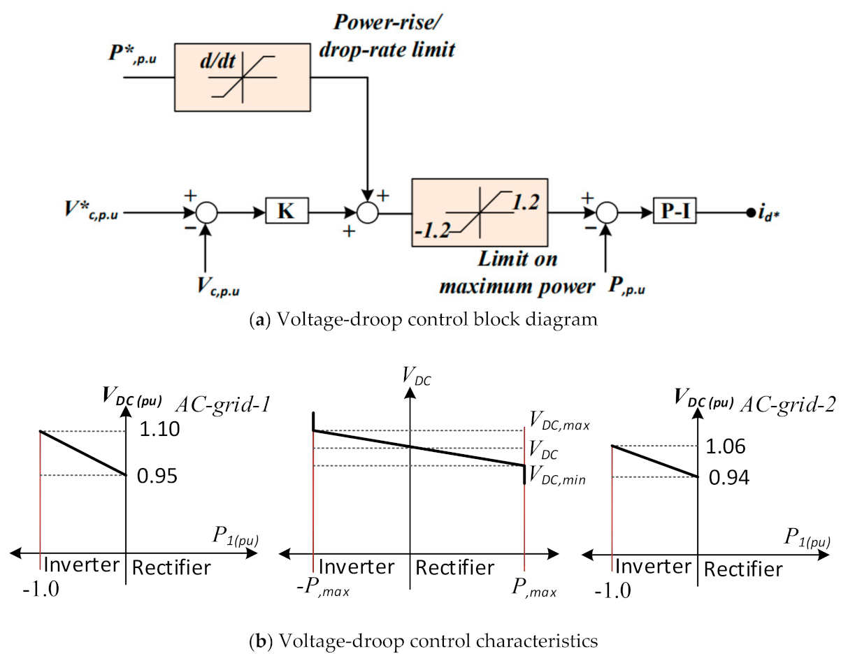
2.3. Voltage-Droop Control

The DC-voltage regulation within VSC-based MT-HVDC grids has the most significance, as it can only fluctuate in a small range. The voltage difference at the VSC-based MT-HVDC system’s various stations directly affects the DC power-flow in the VSC-based MT-HVDC stations. It is important to note that un-like AC networks, where specified and similar voltage amplitudes (usually 1 p.u) are suggested across the system, the MT-HVDC system cannot have the same voltage-level throughout the whole network. If the voltage level is the same across the entire network, there will be no power flow within DC stations. The voltage-droop regulation allows the regulation of the DC voltage in the MT-HVDC system by modifying the currents of VSCs in a particular manner where the power balance is ensured over the entire system [10]. In this technique, a proportional controller is used, which shows a droop characteristic that describes the inimitable relation in both the current of VSC and the DC voltage. Figure 4a depicts the block diagram of improved voltage-droop control, while Figure 4b shows the voltage-droop control characteristic. Within reference to Figure 1, Figure 4b indicates that grid side-2 absorbs a larger portion of the wind power than grid side-1. It means that the voltage-droop characteristic of grid side-2 has a lower minimum voltage setting and more downward slope compared to grid side-1 aspects. As a result, grid side-2 has priority in receiving power over grid side-1. In this study, the voltage-droop regulation is employed at the on-shore grid side VSCs, which usually receives the off-shore wind farms’ power to ensure the power balance within MT-HVDC network limits. In contrast, the voltage-droop control parameters are tuned such that the highest and lowest DC voltage levels happen at the highest power of VSC.

3. Optimization Technique Based Artificial Bee Colony Algorithm

Different metaheuristic techniques have been developed to solve mathematical and combinational optimization problems. The metaheuristic optimization techniques are inspired by nature (i.e., physical laws, social actions) to evaluate the search area’s comprehensive and significant developments. Some famous optimization techniques for the optimization solutions are G-A, simulated annealing, particle swarm optimization, ABC, Taboo search, fire-fly method, and so forth. Among these methodologies, the ABC algorithm was suggested by Karaboga in 2005 [25], and since then, has been employed successfully for different engineering applications [26,27,28,29]. The ABC algorithm is comparatively easy, flexible, reliable, and needs fewer regulating parameters [30]. In this paper, the ABC algorithm is proposed to tune the VSC-based MT-HVDC grids’ P-I parameters.
The ABC algorithm has four major elements; initialization, employed, on-looker, and scout bees. The employee bees, on-looker bees, and scout bees are dispatched to search for food sources. During searching, the on-looker bee dispatch to select a better food source. Further, the working bee goes to the food source visited earlier, whereas a scout bee keeps searching randomly for the food source. A comprehensive overview of the applied algorithm is shown in Figure 5. The real-time implementation of the proposed ICC-L controller is illustrated in Figure 6. Here, real-time input and feedback for signals are given to the ABC algorithm to find an optimal solution. Further, optimal values implement in the VSC-controller to improve transient and steady-state response. The OCC-L controller parameters are optimized similarly by implementing the ABC algorithm.

3.1. Initial Population

In the first step, the ABC algorithm produces the initial population, which contains n f s n . Here, n f s n is the food-source number, and it is equal to the number of employed bees. The initial population ( w i j ) of the ABC algorithm is generated as:
w i j = w min , j + ( w max , j w min , j ) × r a n d o m ( 0 , 1 ) ( i = 1 n f s n ) ( j = 1 n p n ) ,
  • n p n represent parametric numbers,
  • w min , j indicate the lower limit of the initial population’s parameters,
  • w m a x , j indicate the upper limit, respectively.

3.2. Employee Bees

The employee bees seek a new food source ( U i ,   j ) having more nectar quantity in the food source neighborhood ( w i j ). They discover a new food source in the existing food source’s surroundings and assess its fitness. The new food source ( U i ,   j ) can be represented as:
U i ,   j = w i ,   j + α i ,   j × ( w i ,   j w k ,   j ) ( k = 1 n f s n ) ( i = 1 n f s n k ) ( j = 1 n p n ) ,
  • α i ,   j is a random number between [−1, 1],
  • U i ,   j is the new source position,
  • w i j is the previous source position.
A new solution is produced during each iteration. The job of working bees is to evaluate these solutions. While evaluating solutions, the performance of the new source position is compared with the previous source position. If the new solution has better accuracy, it will replace the last position source. Or else, the old solution will retain its position.

3.3. On-Looker Bees

Further, worker bees exchange their food source details with the on-looker bees. The on-looker bees start to look for new food across the specified food source. If the on-looker bees discover higher class food sources, their position will be exchanged with the worker bees. Otherwise, the base value will be increased by 1. The on-looker bees decide a food source based on the probability value indicating through that food source. Mathematically can be stated as below:
c p i = m . f i t n e s s i j = 1 n f s n m . f i t n e s s i ,
  • where m . f i t n e s s i shows the improved fitness of the solution and can be written as:
m . f i t n e s s i = 1 f i t n e s s i ,
  • f i t n e s s i shows the fitness value of the solution.

3.4. Scout Bees

While searching for a new food source, if the on-looker bees base value exceeds the specified limit, then, employed bees abandoned food sources. Hereafter, employed bees are re-produced as the scout bees to discover better food sources via Equation (8).
Every food source in the initial population consists of a set of algorithm parameters. The initial solution’s parameters generated by (8) evolved in each iteration. During evolution, the control parameters are taken as an input to minimize the fitness function described in (12). Whereas the fitness function (f) is characterized by reducing the integral time absolute error (ITAE), as illustrated below:
Min   f = 0 T t | u r u m | d t ,
where T is the optimization-period u r and u m represents the system’s referenced and measured values, respectively. The error term represents the inner current and the outer current controller error in the fitness function. The ABC algorithm attempts to minimize the fitness function (f) during the offline simulation mode. Subsequently, tuned controllers are used to regulate the power in the MT-HVDC grid.

3.5. Tuning of Inner-Current Control Loop (ICC-L)

The ICC-L is the key element of the VSC controller structure. Enhancing the ICC-L’s P-I parameters by applying the ABC based on multiobjective function is of utmost importance to optimal gain. Figure 7 depicts the ICC-L control structure based on the ABC technique. For optimal gain of the ICC-L, the ( u r ) and ( u m ) in (12) represents the referenced and measured d-axis currents, respectively, as described below:
Min   I C C L = 0 T t . | i d i d , r e f | . d t ,
  • whereas i d represent corresponding d-axis current,
  • i d , r e f represent referenced-axis current.

3.6. Tuning of Outer-Current Control Loop (OCC-L)

After the optimization of the ICC-L, the tuning of the OCC-L is carried out. Figure 8 shows the control structure of OCC-L based on ABC optimization. The objective function for outer controllers is:
Min   O C C L = 0 T t . | P P r e f | . d t .
The aim of Equations (13) and (14) is to minimize the parametric difference between controlled and set variables, where t is time. While doing so, the ABC algorithm utilizes the various set of values of P-I controller parameters to minimize the multiobjective function. Theoretically, by minimizing the time-integral-based multiobjective function and enhance the filtering process, the dynamic response of the VSC improves [31].

4. Execution of the Multiobjective Functions

Simultaneous optimizations of the various objective-functions are obtained by applying the multiobjective-function (MO-F). In this study, the MT-HVDC network’s quick response during dynamic conditions is attained by minimizing the multiobjective function. First of all, the classic constraints are tuned discretely, and then, the metaheuristic technique is employed to find a better compound-solution. Next, the weighted-sum method is used with the ABC optimization technique for paralleled optimization of the objective problems for the ICC-L and OCC-L. Figure 9 shows the control structure of this optimization technique. The selection criteria for the weight is user-specified and self-generated values [32]. Here in this paper, the multiobjective functions are selected as a compound objective problem in the weighted-sum method and mathematically given as:
M O F = i = 1 X i F i ( x ) i = 1 , 2 ,
  • X i shows the nonzero weights. Here, the user-defined set of values describe the preferred criteria of weights.
M O F = X 1 I C C L + X 2 O C C L ,
  • X 1 , X 2 represent the allocated weights and associated with each other as X 2 = 1 X 1 , whereas X 1 variate between 0 and 1.

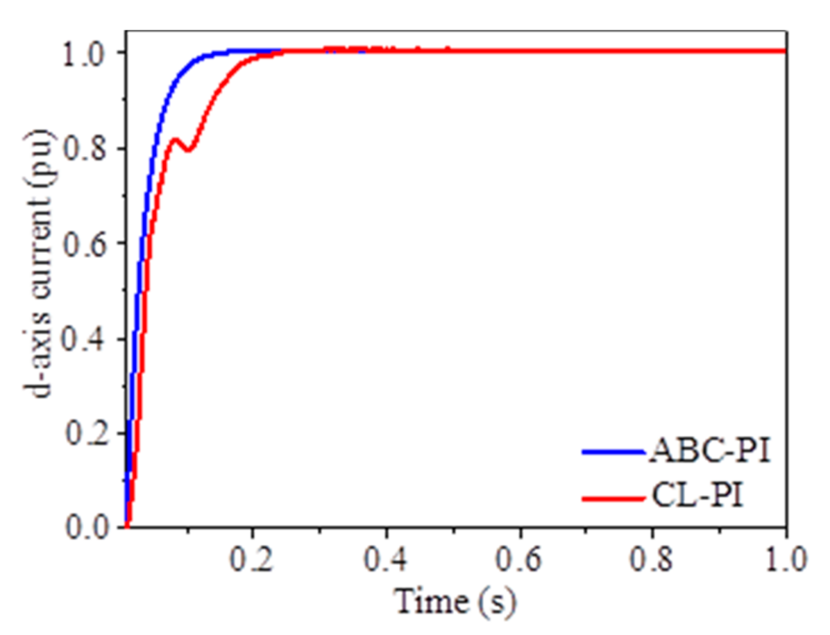
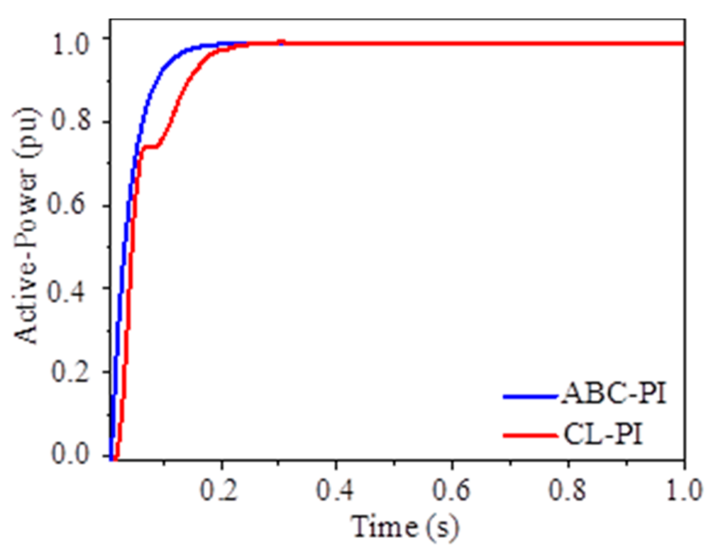
4.1. Comparative Analysis of the Controller’s Efficiency

In this segment, the P-I controller’s parameters are tuned by both the suggested ABC optimization technique based on minimizing the objective function described in (15) and the classical optimization technique. The ABC algorithm parameters are presented in Table 1. For the assessment and comparison, a classically optimized P-I and the ABC tuned P-I controllers are used during the simulation. Accordingly, the ABC Algorithm Pseudo-Code is shown in Appendix A to achieve the optimal VSC controller.

4.2. Tuning of ICC-L Based on the Classical Optimization Method

The classically optimized P-I controller’s parameters are based on the concepts described in [22,33].
  • The ICC-L’s closed-loop bandwidth must be 1/5 times lower than the angular switching- frequency to attain adequate efficiency.
  • The inner current controllers must be ten times faster than outer controllers to achieve a closed-loop system free from the oscillating response.
Thus, the P-I controller’s parameters for the ICC-L are chosen as [34]:
k I C , p α I C × L T S p . u ,
k I C , i α I C × R T S p . u .
Here, α I C represents closed-loop bandwidth for the inner current controller, and 2 kHz is set as the switching frequency in this study. It is illustrated as:
α I C 2 × 2 × π 5 = 4 × π 5 = 2.513 k   rad / s .
Considering the safety factors, the value 2 k   rad / s is the selected closed-loop bandwidth based on (17) and (18). Whereas the calculated parameters of ICC-L are presented in Table 2.

4.3. Tuning of ICC-L Based on the Classical Optimization Method

Similarly, the OCC-L parameters are tuned on the basic principle that OCC-L should be 10 times slower than ICC-L to attain a closed-loop without oscillating response. Hence, the bandwidth of the OCC-L is:
α o c 1 10 = 0.1 α I C .
Then, based on the concept proposed in [35], the k P and k i values are derived and given by:
k O C , p α O C C p . u ,
k O C , i α O C 2 C p . u .
The active power controller’s parameters, integral time absolute error (ITEA), obtained by applying the classical optimization technique in (21) and (22), are given in Table 3.

4.4. Multiobjective Optimization of ICC-L and OCC-L Based on ABC Algorithm

Multiobjective optimization based on the ABC algorithm for ICC-L and OCC-L is employed for one VSC terminal. Then, the optimal P-I parameters are employed on the other VSCs terminals as well. Hence, to attain the optimum k p and k i values, the ABC algorithm is implemented.
Figure 10 depicts the value of the fitness function during the ABC-based multiobjective optimization. As the iteration’s numbers increase, the algorithm evolves towards minimization, which generates the ICC-L and OCC-L’s optimum values. The values for ICC-L and OCC-L controllers develop in a specific iteration of the algorithm. These evolved values help to optimize the fitness function, which produces optimized k p and k i values in return. Optimal tuned P-I parameters for ICC-L and OCC-L based on the ABC algorithm and classical tuned technique [33], Ref. [22] are shown in Table 3.
A classic step-response of ICC-L is employed to compare and evaluate the objective function based on the suggested technique. Figure 11 exhibits the step-response of the ICC-L for the ABC algorithm and classically tuned P-I. Meanwhile, the step-response of the active power obtained by ABC P-I and CL P-I can be seen in Figure 12.
The graphical results of Figure 11 and Figure 12 present that ABC-PI controllers have significantly enhanced performance, clearly the quick rise time compared with CL P-I controllers.
Hence, given the discussion as mentioned above, it is visualized from the simulation results from Figure 11 to Figure 12 that the VSC response significantly improves, and the conversion response is much better via implementing the ABC algorithm.
In order to present a meaningful numerical evaluation of the performance of the CL P-I and ABC P-I controllers, the comparison is carried out in terms of minimizing the integral of time multiplication by absolute error (ITAE) measures based on (13), (14), and (16), in Table 3.
Table 3 gives the smallest convergence values obtained for the integral time absolute error (ITEA). While running the ABC algorithm for the given VSC controller, 60 iterations ran using MATLAB workspace. After exited the optimization loop, PI parameters with the smallest convergence unit are chosen. Meanwhile, several ITEA-based non-convex algorithms have used ITEA with four decimal places, as given in [36].

5. Simulation Results

The four-terminal MT-HVDC network test system is illustrated in Figure 1. This test system is used to assess the efficiency of the proposed controllers. It contains two off-shore wind power farms and two on-shore mainland AC grids. In mainland AC grids, VSC terminals (VSC1, VSC2) are configured to balance the DC-link voltages through the P-Vdc droop controller and reactive-power regulation [13]. This setup helps control the actual power transformation between AC and DC grids and regulates the DC-link voltages. Besides, VSC3 and VSC4 are designed to handle the P-Vac to provide a steady-state flow of power in the DC terminals [1], plus regulates the AC voltages at PCC. The DC-link voltage works within ± 250.00   k V , and the VSC-based MT-HVDC network ratings are shown in Table 4.
The VSC setup in each station is similar since the optimization procedure is executed on a single VSC terminal, and achieved control parameters are applied on all four VSC terminals. To assess the validation and robustness of the suggested control technique, three separate scenarios were tested, including:
  • Unbalance wind power,
  • Unbalanced power demand at the AC grids side,
  • Eventual VSC disconnection.

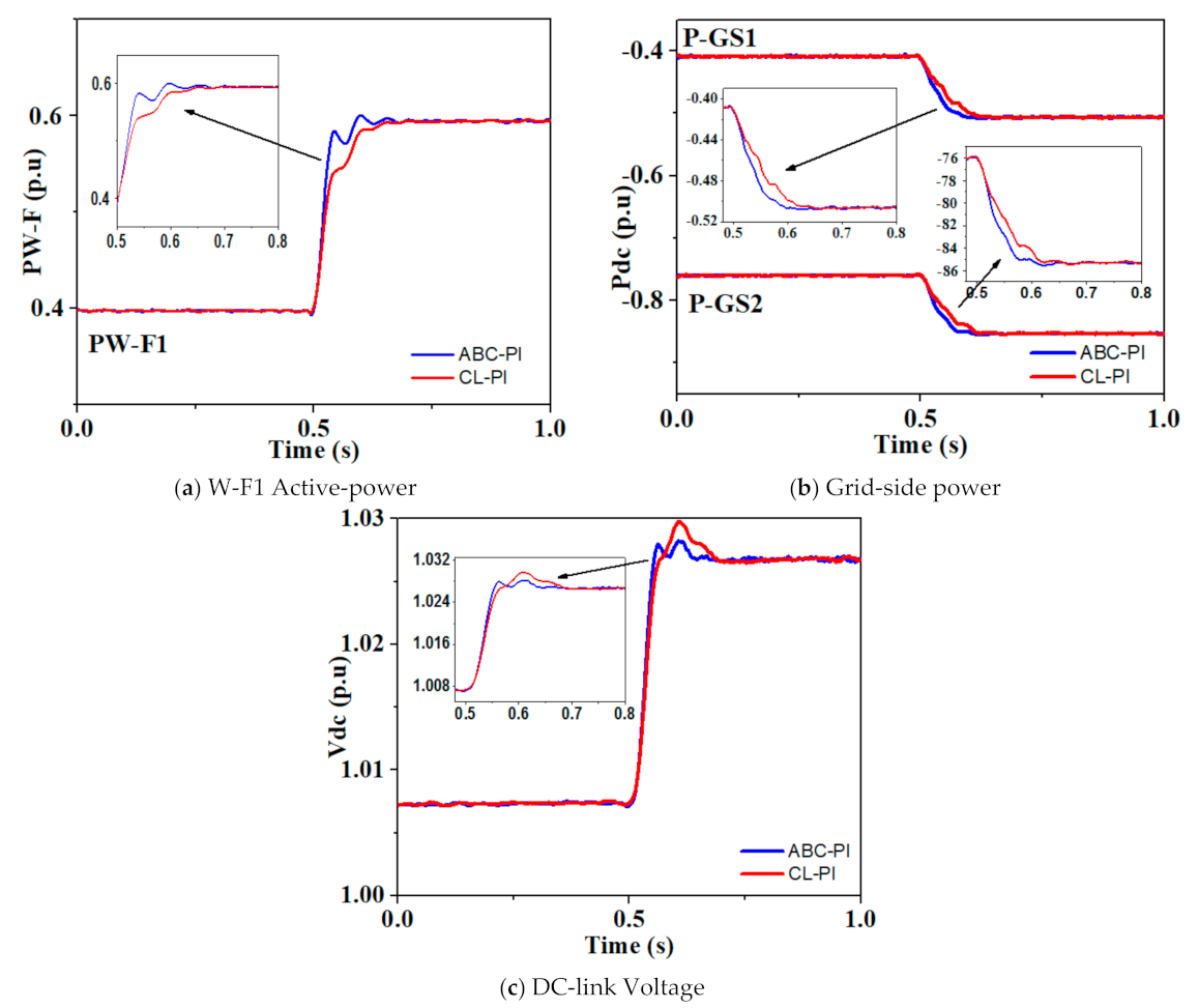
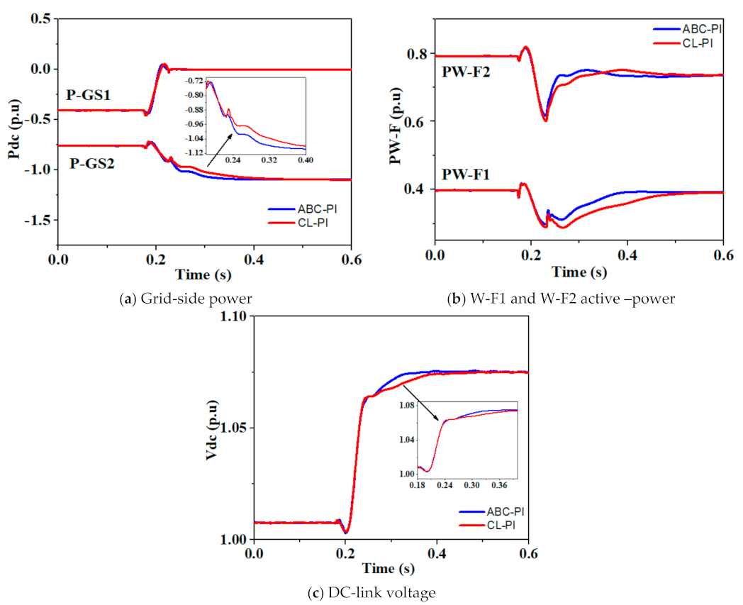
5.1. Unbalance Wind Power

Scenario 1 is based on the condition in which the W-F1 and W-F2 power changes were made. Figure 13 and Figure 14 show the more satisfactory results of the proposed multiobjective ABC controller with quick rise time and the system’s stability compared with classically tuned controllers.
In this scenario, simulation starts at 0.40 and 0.80 p.u, produced by the W-F1 and W-F2. This condition goes up to t = 0.50 s smoothly, and then suddenly, at t = 0.50 s, WF-1 under P-Q control raises the power production 0.40 to 0.60 p.u. As the voltage-droop regulation is applied on the on-shore grid side, VSC terminals at the grid side rapidly track and respond to the changes. Grid-1 and grid-2 are two grid sides with P-Vac and P-Q control settings. The P-Vac control setup is employed when VSC stations are linked to weak grids, and low power must be constant. AC voltages and active powers are controlled through VSC-based HVDC, while the P-Q control technique is applied when VSC stations are attached to stiff AC grids for constant power requirements. While visualizing Figure 13a,c, there is a small fluctuation during the transition process. However, the transition fluctuation is within the safe limit [13,37]. Moreover, the convergence rate of the proposed model is much better.

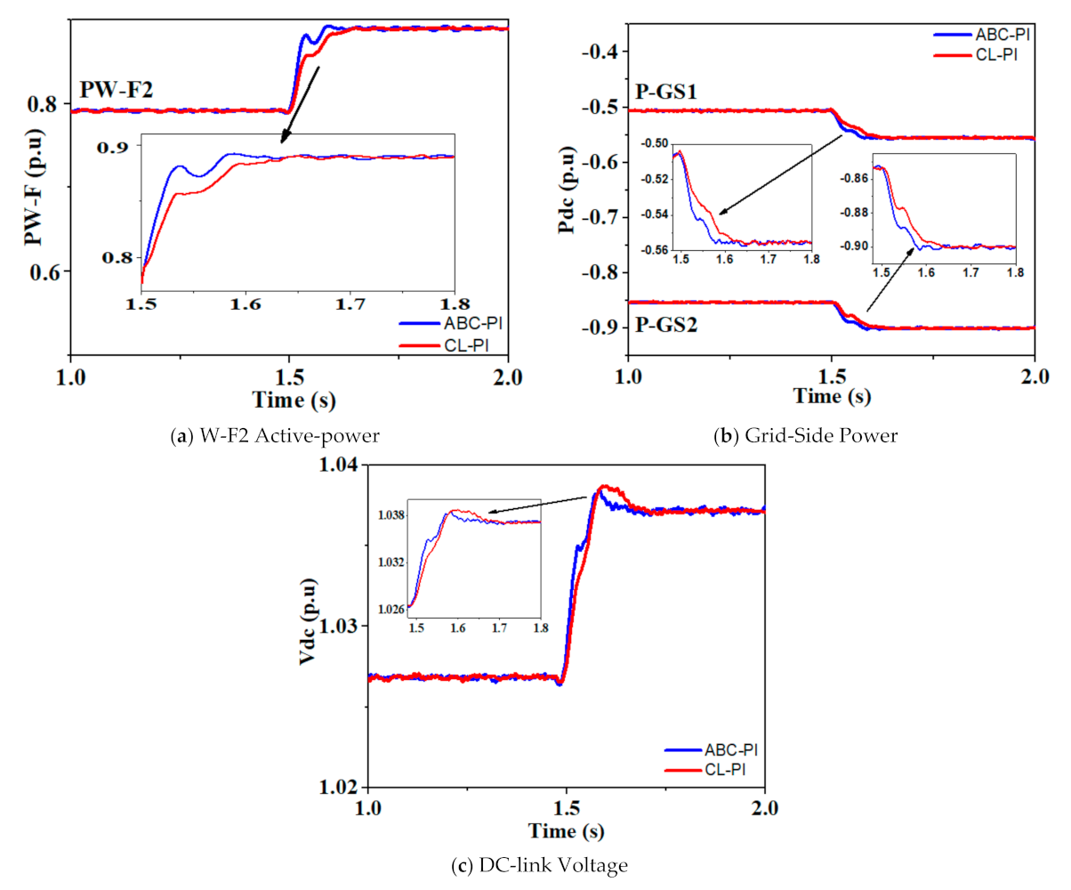
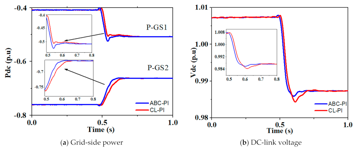
5.2. Unbalanced Load Demand at AC Grids

In the second scenario, the proposed controllers are evaluated when the power demand changes at the AC grid side. A voltage-droop controller is employed at the on-shore side grid VSCs are P-Q and P-Vac control, respectively. To validate the desirable results of the control method implemented on the grid side, a comparison between the classic tuned P-I and ABC optimized P-I is shown in Figure 15.
The simulation starts at normal values 0.40 and 0.80 p.u; the power production by W-F1 and W-F2. Then suddenly, at t = 0.50 s, the P-GS1 increases from −0.40 to −0.50 p.u due to this sudden change in load demand tracked by the other AC grid-2. Since the voltage-droop regulator is used at the on-shore grid side to regulate the voltage, P-GS2 changes from −0.75 to −0.65 p.u. In Figure 15a, power change at the on-shore grid sides P-GS1, P-GS2 can be seen. Graphical results show that the ABC optimized controllers stabilize the system, and DC voltage attains steady-state faster than classic tuned P-I. The DC-link voltage during the unbalanced load demand at on-shore grids settles within the safe limit proposed stable limit [13,37].

5.3. Eventual VSC Disconnection

In scenario three, a three-phase fault is implemented to on-shore grid-1 at t = 0.2 s to assess MT-HVDC’s stability efficiency. For this analysis, a three-phase fault is implemented to AC grid-1. Figure 16 shows that at-fault occurring time, off-shore grids indicate negligible impacts in their production of power and rapidly return to original conditions.
In a normal situation, the total output power of P-WF1 and P-WF2 is 1.2 p.u, and on-shore grids divide the generated power accordingly to voltage-droop control. Nevertheless, when a fault happens to on-shore grid-1 at t = 0.2 s, the produced power switches quickly to on-shore grid-2, and the power of grid-1 (P-GS1) becomes zero. Meanwhile, the on-shore grid-2 controller facilitates the P-GS1 and DC-link voltages to meet the output levels’ requirements immediately. ABC base controller shows a quick response than a classically tuned controller. The DC-link voltages become stable within ±10% of mentioned in [37], in all cases, which clearly shows that the implemented control algorithm performs well.

6. Conclusions

The artificial bee colony algorithm, the multiobjective optimization based on the metaheuristic approach, is proposed to optimize VSC-based MT-HVDC networks’ control parameters. The ICC-L and OCC-L of VSC in the MT-HVDC were tuned simultaneously using the proposed multiobjective ABC algorithm to reveal the dynamic performance. Then, the tuned parameters were used in the four-terminal MT-HVDC system to evaluate the controller performance in the PSCAD/EMTDC. A relative comparison with the proposed technique, the classical approach is also tested under dynamic conditions. The ITAE of the proposed ABC algorithm is better than classical tuned methods, as shown in Table 4. The simulation assessments established in both transient and steady-states indicate significantly improved progress and better convergence performance than classical optimized controllers, which is verified from Figure 13, Figure 14, Figure 15 and Figure 16. The stability and dynamic performance of the proposed system are also satisfactory.

Author Contributions

Conceptualization, M.A.K.; methodology, M.A.K. and X.L.; software, M.A.K.; validation, M.A.K. and M.Z.Y.; mathematical analysis, M.A.K. and M.Z.Y.; investigation, M.A.K.; resources, X.L.; writing original draft preparation, M.A.K.; writing review and editing, X.L. and A.M.; visualization, X.L.; supervision, X.L.; project administration, M.A.K., M.W. and M.Z.Y.; funding acquisition, X.L. All authors have read and agreed to the published version of the manuscript.

Funding

This research received no external funding.

Institutional Review Board Statement

Not applicable.

Informed Consent Statement

Not applicable.

Data Availability Statement

Not applicable.

Acknowledgments

This research is supported by the National Natural Science Foundation of China (51267001).

Conflicts of Interest

The authors declare no conflict of interest.

Appendix A

ABC Algorithm Pseudo-Code
Initialization
(1) C (cycle number) = 1
(2) Initialize a random population (solutions) (Wi,j), i = 1 n f s n , j = 1 n p n
(3) Evaluate the population (fitness function based on Equation (12)
(4) Repeat
(5) Employee Bee Phase
    For each employee bee
    Generate a new population (food source) U i ,   j
   Calculate the fitness values k I C , p and k I C , i
If new solution is better than the previous solution
Then memorize the new solution and apply the greedy selection
End for.
(6) Evaluate the probability c p i of the solution
(7) On-looker Bees Phase
    For each on-looker bee
    Select a solution depends on c p i
    Generate the new solution U i ,   j
    Evaluate the fitness values k I C , p and k I C , i
If new solution is better than the previous solution
Then memorize the new solution and apply greed selection
End for
(8) Scout Bees Phase
If there is an employee bee becomes a scout
Then replace it with a new random population
(9) Memorizing the best solution
(10) C = C +1
(11) Until C = Maximum cycle number (i.e., 120 in our case) and satisfy minimization of objective function = M O F = X 1 I C C L + X 2 O C C L

References

  1. Liang, J.; Jing, T.; Gomis-Bellmunt, O.; Ekanayake, J.; Jenkins, N. Operation and control of multiterminal HVDC transmission for offshore wind farms. IEEE Trans. Power Deliv. 2011, 26, 2596–2604. [Google Scholar] [CrossRef]
  2. Rao, H. Architecture of Nan’ao multi-terminal VSC-HVDC system and its multi-functional control. CSEE J. Power Energy Syst. 2015, 1, 9–18. [Google Scholar] [CrossRef]
  3. Hannan, M.; Hussin, I.; Ker, P.J.; Hoque, M.M.; Lipu, M.H.; Hussain, A.; Rahman, M.A.; Faizal, C.; Blaabjerg, F. Advanced control strategies of VSC based HVDC transmission system: Issues and potential recommendations. IEEE Acces 2018, 6, 78352–78369. [Google Scholar] [CrossRef]
  4. Mobarrez, M.; Kashani, M.G.; Bhattacharya, S. A novel control approach for protection of multiterminal VSC-based HVDC transmission system against DC faults. IEEE Trans. Ind. Appl. 2016, 52, 4108–4116. [Google Scholar] [CrossRef]
  5. Zhang, S.; Zou, G.; Huang, Q.; Xu, B.; Li, J. Single-ended line protection for MMC-MTDC grids. IET Gener. Transm. Distrib. 2019, 13, 4331–4338. [Google Scholar] [CrossRef]
  6. Liu, Y.; Xie, S.; Liang, H.; Cui, H. Coordinated control strategy of multi-terminal VSC-HVDC system considering frequency stability and power sharing. IET Gener. Transm. Distrib. 2019, 13, 5188–5196. [Google Scholar] [CrossRef]
  7. Li, J.; Li, Y.; Xiong, L.; Jia, K.; Song, G. DC fault analysis and transient average current based fault detection for radial MTDC system. IEEE Trans. Power Deliv. 2019, 35, 1310–1320. [Google Scholar] [CrossRef]
  8. Wu, G.; Liang, J.; Zhou, X.; Li, Y.; Egea-Alvarez, A.; Li, G.; Peng, H.; Zhang, X. Analysis and design of vector control for VSC-HVDC connected to weak grids. CSEE J. Power Energy Syst. 2017, 3, 115–124. [Google Scholar] [CrossRef]
  9. Lu, S.; Xu, Z.; Xiao, L.; Jiang, W.; Bie, X. Evaluation and enhancement of control strategies for VSC stations under weak grid strengths. IEEE Trans. Power Syst. 2017, 33, 1836–1847. [Google Scholar] [CrossRef]
  10. Rouzbehi, K.; Miranian, A.; Candela, J.I.; Luna, A.; Rodriguez, P. A generalized voltage droop strategy for control of multiterminal DC grids. IEEE Trans. Ind. Appl. 2014, 51, 607–618. [Google Scholar] [CrossRef]
  11. Yang, X.; Hu, H.; Ge, Y.; Aatif, S.; He, Z.; Gao, S. An improved droop control strategy for VSC-based MVDC traction power supply system. IEEE Trans. Ind. Appl. 2018, 54, 5173–5186. [Google Scholar] [CrossRef]
  12. Rouzbehi, K.; Miranian, A.; Candela, J.I.; Luna, A.; Rodriguez, P. A hierarchical control structure for multi-terminal VSC-based HVDC grids with GVD characteristics. In Proceedings of the 2013 International Conference on Renewable Energy Research and Applications (ICRERA), Madrid, Spain, 20–23 October 2013; pp. 996–1001. [Google Scholar]
  13. Raza, A.; Dianguo, X.; Yuchao, L.; Xunwen, S.; Williams, B.; Cecati, C. Coordinated operation and control of VSC based multiterminal high voltage DC transmission systems. IEEE Trans. Sustain. Energy 2015, 7, 364–373. [Google Scholar] [CrossRef] [Green Version]
  14. Yousaf, M.Z.; Liu, H.; Raza, A.; Baig, M. Primary and backup fault detection techniques for multi-terminal HVdc systems: A review. IET Gener. Transm. Distrib. 2020, 14, 5261–5276. [Google Scholar] [CrossRef]
  15. Seng, T.L.; Khalid, M.B.; Yusof, R. Tuning of a neuro-fuzzy controller by genetic algorithm. IEEE Trans. Syst. Man Cybern. Part B 1999, 29, 226–236. [Google Scholar] [CrossRef] [PubMed]
  16. Song, E.; Lynch, A.F.; Dinavahi, V. Experimental validation of nonlinear control for a voltage source converter. IEEE Trans. Control Syst. Technol. 2009, 17, 1135–1144. [Google Scholar] [CrossRef]
  17. Gaing, Z.-L. A particle swarm optimization approach for optimum design of PID controller in AVR system. IEEE Trans. Energy Convers. 2004, 19, 384–391. [Google Scholar] [CrossRef] [Green Version]
  18. Krohling, R.A.; Rey, J.P. Design of optimal disturbance rejection PID controllers using genetic algorithms. IEEE Trans. Evol. Comput. 2001, 5, 78–82. [Google Scholar] [CrossRef]
  19. Hassan, L.H.; Moghavvemi, M.; Almurib, H.A.; Muttaqi, K.M. A coordinated design of PSSs and UPFC-based stabilizer using genetic algorithm. IEEE Trans. Ind. Appl. 2014, 50, 2957–2966. [Google Scholar] [CrossRef]
  20. Lotfy, M.E.; Senjyu, T.; Farahat, M.A.; Abdel-Gawad, A.F.; Yona, A. Enhancement of a small power system performance using multi-objective optimization. IEEE Access 2017, 5, 6212–6224. [Google Scholar] [CrossRef]
  21. Dierckxsens, C.; Srivastava, K.; Reza, M.; Cole, S.; Beerten, J.; Belmans, R. A distributed DC voltage control method for VSC MTDC systems. Electr. Power Syst. Res. 2012, 82, 54–58. [Google Scholar] [CrossRef] [Green Version]
  22. Pinto, R.T.; Bauer, P.; Rodrigues, S.F.; Wiggelinkhuizen, E.J.; Pierik, J.; Ferreira, B. A novel distributed direct-voltage control strategy for grid integration of offshore wind energy systems through MTDC network. IEEE Trans. Ind. Electron. 2012, 60, 2429–2441. [Google Scholar] [CrossRef]
  23. Bajracharya, C.; Molinas, M.; Suul, J.A.; Undeland, T.M. Understanding of tuning techniques of converter controllers for VSC-HVDC. In Proceedings of the Nordic Workshop on Power and Industrial Electronics (NORPIE/2008), Espoo, Finland, 9–11 June 2008; Helsinki University of Technology: Espoo, Finland, 2008. [Google Scholar]
  24. Akagi, H.; Watanabe, E.H.; Aredes, M. Instantaneous Power Theory and Applications to Power Conditioning; John Wiley & Sons: Hoboken, NJ, USA, 2017. [Google Scholar]
  25. Karaboga, D. An Idea Based on Honey Bee Swarm for Numerical Optimization; Technical report-tr06; Erciyes University, Faculty of Engineering, Department of Computer Engineering: Kayseri, Turkey, 2005. [Google Scholar]
  26. Ayan, K.; KILIÇ, U. Solution of transient stability-constrained optimal power flow using artificial bee colony algorithm. Turk. J. Electr. Eng. Comput. Sci. 2013, 21, 360–372. [Google Scholar]
  27. Şahin, A.Ş.; Kılıç, B.; Kılıç, U. Design and economic optimization of shell and tube heat exchangers using Artificial Bee Colony (ABC) algorithm. Energy Convers. Manag. 2011, 52, 3356–3362. [Google Scholar] [CrossRef]
  28. Kılıç, U.; Ayan, K. Optimizing power flow of AC–DC power systems using artificial bee colony algorithm. Int. J. Electr. Power Energy Syst. 2013, 53, 592–602. [Google Scholar] [CrossRef]
  29. Karaboga, N. A new design method based on artificial bee colony algorithm for digital IIR filters. J. Frankl. Inst. 2009, 346, 328–348. [Google Scholar] [CrossRef]
  30. Holland, J. Adaptation in Natural and Artificial Systems; MI University of Michigan Press: Ann Arbor, MI, USA, 1975. [Google Scholar]
  31. Tareen, W.U.K.; Aamir, M.; Mekhilef, S.; Nakaoka, M.; Seyedmahmoudian, M.; Horan, B.; Memon, M.A.; Baig, N.A.J.E. Mitigation of power quality issues due to high penetration of renewable energy sources in electric grid systems using three-phase APF/STATCOM technologies: A review. Energies 2018, 11, 1491. [Google Scholar] [CrossRef] [Green Version]
  32. Marler, R.T.; Arora, J.S. The weighted sum method for multi-objective optimization: New insights. Struct. Multidiscip. Optim. 2010, 41, 853–862. [Google Scholar] [CrossRef]
  33. Rouzbehi, K.; Miranian, A.; Luna, A.; Rodriguez, P. Optimized control of multi-terminal DC GridsUsing particle swarm optimization. In Proceedings of the 2013 15th European Conference on Power Electronics and Applications (EPE), Lille, France, 2–6 September 2013; pp. 1–9. [Google Scholar]
  34. Rodrigues, S.; Bauer, P.; Bosman, P.A.J.R.; Reviews, S.E. Multi-objective optimization of wind farm layouts–Complexity, constraint handling and scalability. Renew. Sustain. Energy Rev. 2016, 65, 587–609. [Google Scholar] [CrossRef] [Green Version]
  35. Rodrigues, S.M.F.; Pinto, R.T.; Bauer, P. Dynamic Modeling and Control of VSC-based Multiterminal DC networks. Inst. Super. Técnico 2011. [Google Scholar]
  36. Faisal, S.F.; Beig, A.R.; Thomas, S.J.E. Time domain particle swarm optimization of PI controllers for bidirectional VSC HVDC light system. Energies 2020, 13, 866. [Google Scholar] [CrossRef] [Green Version]
  37. Beerten, J.; Cole, S.; Belmans, R. Modeling of multi-terminal VSC HVDC systems with distributed DC voltage control. IEEE Trans. Power Syst. 2013, 29, 34–42. [Google Scholar] [CrossRef] [Green Version]
Figure 1. Four terminal Voltage-Source Converters-based (VSCs), Multiterminal High Voltage Direct-Current (MT-HVDC) transmission network, contains two on-shore AC-grids and two wind-farms.
Energies 14 01578 g001
Figure 2. Single line diagram of d-q vector-control for the VSC-based MT-HVDC station.
Energies 14 01578 g002
Figure 3. The structure of the inner-current control loop (ICC-L).
Energies 14 01578 g003
Figure 4. (a) Voltage-droop control block diagram, (b) Voltage-droop control characteristics.
Energies 14 01578 g004
Figure 5. A flowchart of the Artificial Bee Colony (ABC) algorithm.
Energies 14 01578 g005
Figure 6. Procedure of ABC algorithm on P-I controllers.
Energies 14 01578 g006
Figure 7. ABC-based control structure of ICC-L.
Energies 14 01578 g007
Figure 8. ABC-based control structure of Outer-Current Control Loop (OCC-L).
Energies 14 01578 g008
Figure 9. ABC-based multiobjective tuning of Voltage-Source Converters (VSCs). The minimization of the compound-objective function (15) helps achieve the multiobjective function’s optimization goals. In this situation, the goal is to set a setup containing two different objective functions, (13) and (14). Each objective function’s weight evaluates a compromised function, while the weight selection describes each element’s significance in (16). Therefore, the overall objective function represents as:
Energies 14 01578 g009
Figure 10. ABC algorithm performance for multiobjective optimization of Voltage-Source Converter (VSC).
Energies 14 01578 g010
Figure 11. Step-response of the inner-current controller (ICC-L) for classical tuned PI and Artificial Bee Colony (ABC-PI).
Energies 14 01578 g011
Figure 12. Active power step-response for classical tuned PI and ABC-PI.
Energies 14 01578 g012
Figure 13. (a) W-F1 Active-power, (b) grid-side power, (c) DC-link voltage during unbalance wind power generation at W-F1.
Energies 14 01578 g013
Figure 14. (a) W-F2 active-power, (b) Grid-side power, (c) DC-link voltage during unbalance power generation at W-F2. The referenced-based configuration is assigned to active and reactive power with controlled operating modes. Since the voltage-droop control is employed at the on-shore side grid, at t = 0.50 s, the P-GS1 and P-GS2 change from −0.40 to −0.50 p.u and −0.76 to −0.86 p.u, respectively, due to a sudden rise in power generation of W-F1. This surplus generated power is divided into the AC grids based on the voltage-droop control characteristics similarly, as W-F2 raises its power output from 0.8 to 0.9 p.u. is shown in Figure 13a–c and Figure 14a–c. Moreover, concerning the voltage drop characteristics in Figure 4, the variation of DC-link voltage during unbalance power generation at W-F2 in Figure 13 and Figure 14 is well within the safe and HVDC network operational limits [13,37]. Further, the slope of voltage droop characteristics for GS-2 is smaller than GS-1, demonstrating that GS-2 absorbs more power than GS-1 generated by the wind farms.
Energies 14 01578 g014
Figure 15. (a) Grid-side power, (b) DC-link voltage during unbalance load demand at on-shore grid-1.
Energies 14 01578 g015
Figure 16. (a) Grid-side power, (b) W-F1 and W-F2 active-power, (c) DC-link voltage during dis-connection of grid-1.
Energies 14 01578 g016
Table 1. Artificial Bee Colony (ABC) algorithm parameters.
SpecificationsNumber of Food-SourceBees (Employeed + On-Looker Bees)Iterations
Values202060
Table 2. P-I controller’s parameters achieved by ABC and classical optimization method for ICC-L and OCC-L.
ControllersCL P-I ABC P-I
k p T i = 1 / k i k p T i = 1 / k i
ICC-L0.4816.75000.8721.6535
OCC-L0.1235.00500.8776.2550
Table 3. Comparison of ABC and classical tuned P-I controllers in terms of integral time absolute error (ITAE).
Controllers ITAE
CL P-IABC P-I
ICC-L4.82208 × 10−49.5642 × 10⁻⁵
Active power1.6402 × 10−34.8640 × 10⁻⁴
MO-F 5.1532 × 10⁻⁵
Table 4. Parameters of Mutiterminal High Voltage Direct Current (MT-HVDC) network.
ComponentNominal-Voltage (kV)ImpedanceDescription
Wind-farms330.002 + j0.012 (p.u)1000 MVA
AC grids2200.001 + j0.0125 (p.u)1000 MVA
Phase-reactor1800.02 + 0.15 (p.u)
DC-capacitor±2501200 µF, two capacitors in series
DC link±250R = 0.20 × 10⁻² 10 Ω/km
L = 0.55 × 10⁻⁴ H/km
C = 2.2 × 10⁻⁷ F/km
100 km b/w all terminals
Publisher’s Note: MDPI stays neutral with regard to jurisdictional claims in published maps and institutional affiliations.

