Abstract
Automated vehicles are becoming popular across the communities of e-transportation across the globe. Hybrid electric vehicles and autonomous vehicles have been subjected to critical research for decades. The research outcomes pertinent to this topic in the literature have been motivated by the industry and researchers to emphasize automated vehicles. Part 1 of this survey addressed the critical aspects that concern the bidirectional converter topologies and condition monitoring activities. In the present part, 24- and 77-GHz low-profile printed antennas are studied for automotive radar applications. These antennas are mounted on automated vehicles to avoid collision and are used for radio tracking applications. The present paper states the types of antenna structures, feed mechanisms, dielectric material requirements, design techniques, performance parameters, and challenges at 24- and 77-GHz resonating frequency applications. The recent developments in feed methodologies, beam scanning concepts, and the effect of sidelobe levels are addressed. Furthermore, the reasons behind the transition from 24 to 77 GHz are reported in detail. The recent advances in the application of various sensor schemes in an automated vehicle have also been discussed.
1. Introduction
For modern comfort, vehicle safety, and drone-monitoring systems, automotive radar is a critical technological module. Advancing and enabling the autonomous-driving functions and drone monitoring systems associated with camera-involved sensor systems, Lidar and Radar will be in the market very soon. For collision avoidance, more than ten radar elements or sensors are needed in driverless vehicles or next-generation drones to have a 360-degree surrounded view. Consequently, there is a higher demand from the aerospace, defense sectors, and automotive industry for radar systems with multifunctional capabilities and high precision. Hence, these radar systems with multiple features required modern integrated antennas to capture or sense the surroundings to perform the necessary action, which is essential to avoid the collision in an autonomous drone or assist the driver in an autonomous vehicle, respectively. However, the increased requirements led to a focus on research and development in the automotive or anti-collision radar antenna systems in both academia and industrial sectors [1]. Automotive radar is used to detect the range and speed of objects near the vehicle or drone. The automotive radar consists of a transceiver, which is a combination of a transmitter and a receiver. The transmitter emits radio waves that knock the body of the object and spring back to the receiver, determining the speed, distance, and direction of the object.
Sensors and low-profile antennas are required for ubiquitous automotive Radar applications such as:
- Safer passenger transport systems: road, rail, and water;
- Bio-signal detection for healthcare and elderly/baby monitoring;
- Security systems in airport; and urban areas;
- Civil engineering (structural-health monitoring, land-slide monitoring, and ground penetration to detect pipelines, electrical wires, etc.);
- Disseminated surveillance system (smart city, airport, bank, and school);
- Millimeter-wave body scanner to ensure safety;
- Environmental-monitoring and civil defense through anti-collision drones;
- Monitoring industrial measurements in harsh environments without interaction; and
- Groove wall target detection.
Today, a typical-automotive-radar module contains five main functional modules: an antenna, RF-module, signal processor, high-speed-digital-interface, and power module. The automotive-radar systems use two types of antennas, they are Horizontal and Vertical polarized antennas or noted as H, and V. V is the old-style type. The advantage of V is less clutter, but the azimuth (horizontal deviation angle) FoV (Field of View) is limited because the radiation direction of the single element patch V radiator is narrow. Similarly, horizontal polarization requires a wider azimuth FoV, but more ripples will appear in the final target pattern.
Low-profile integrated antennas with all the advantages mentioned above are necessary for automotive or collision avoidance radar applications. In this review article, low-profile automotive radar antennas with various antenna performance parameters were discussed. There are 40 articles of microtrip-based antennas with fabrication and measurements operation in the vicinity of 24 and 77 GHz in automotive or anti-collision radar applications. Around 12 articles were published on 24-GHz automotive radar antennas since 2001, and 19 articles are available on 77-GHz automotive radar antennas. The remaining three references are web-based (Texas Instruments and Microwave and RF), IEEE-MTT presentation given by Markus Gardill, and the transition from the 24-GHz to state-of-the-art 77-GHz automotive radar systems.
2. Antennas for Automotive Radar
With or without hands on the steering wheel, automotive electronics make driving safer. The use of battlefield-related, long-term radar-related technology in modern Advanced Driver-Assistance Systems (ADAS) allows you to look forward, backward electronically, and around the corner to warn drivers of potential accidents. Thanks to advanced mixed-signal semiconductors, this automotive radar can be economically and reliably installed in compact modules and utilizes the available spectrum at 24 and 77 GHz as part of a safer driving experience. Radar is only a component of ADAS, but it is a crucial component in modern automotive electronic security support solutions. Other such systems include light detection and ranging (LiDAR) sensors, infrared (IR) sensors for night vision systems, ultrasonic sensors for parking assistance and back-up warning, high-definition (HD) cameras for lane departure warning, and parking assist cameras. In ADAS, a high-power Central Processing Unit (CPU) or field-programmable gate array (FPGA) is used in conjunction with data from different sensors to provide vehicle control corrections, such as collision warnings and avoidance, to prevent vehicles from accelerating into the front of vehicles or pedestrians ahead. ADAS can form the core of an autonomous driving “unmanned” vehicle when equipped with sufficient information and a suitable vehicle control architecture. It is a more advanced version of the “cruise control” system and is available as an option for commercial vehicles. Three types of radars are installed in ADAS-equipped vehicles: (1) Short-Range Radar (SRR), which is used to detect objects about 1 to 20 m from the car. This includes blind spot detection (BSD) and lane change assistance (LCA); (2) medium-range radar (MRR) to detect objects from 1 to 60 m; and (3) long-range radar (LRR) to detect objects at 250 m. Automotive radar sensors are installed to detect objects in the front, rear, and sides of the vehicle (Figure 1). Both pulse Doppler and continuous wave frequency-modulated continuous-wave (FMCW) radar technology can serve ADAS applications at 24 or 77 GHz. However, 24-GHz systems will be phased out by 2022, and 77-GHz automotive radar systems will be switched. Because the wavelength is one-third of a 24-GHz system, 77-GHz radar can use smaller antennas and other components while still achieving a broader detection range with higher resolution than a 24-GHz system [2]. The comparison of 24 and 77 GHz automotive radar antennas [3,4] are presented in Table 1. Relative 24 and 77 GHz series fed low-profile automotive radar antenna arrays for electric vehicles are designed and configured as presented in Figure 2.
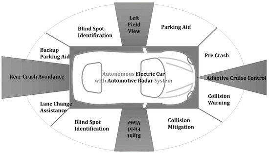
Figure 1.
Possible automotive applications of radar and electric cars installed with multiple radar sensors will be part of the automotive electronic safety system, which will also include cameras and optical sensors.

Table 1.
Comparison of 24- and 77-GHz antenna properties (References [3,4]).
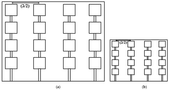
Figure 2.
Schematic of relative 24- and 77-GHz series fed microstrip array configurations. (a) 24 GHz (ℷ ≅ 12 mm), (b) 77 GHz (ℷ ≅ 4 mm).
2.1. Low-Profile 24-GHz Antennas and Arrays
In this section, a review of 24-GHz low-profile antennas is discussed. The design of single and array radiating patch antennas is discussed extensively with empirical formulas, transmission lines, cavity, and full-wave models in the literature [5,6]. The antenna array patterns can be explained directly by operating microstrip patch antenna in the TM01 mode and the analysis of numerical modeling of radiation patterns broadly discussed in [7].
A controlled hole density and dielectric thickness at the center and edges of the lens respectively reported designing the planar Luneburg lens to operate at 24 GHz. The simulation and the experiment made it possible to validate the results at 24 GHz for a bandwidth of 20% following 3 dB half-power-beam-width (HPBW) of 5 degrees with a gain of 14 dB for lens dimensions of 12.2λ and 15.24 cm in diameter. Cross polar levels were below −30 dB, which are useful for SRR applications [8]. Efficient micro-strip feed end-fire angle dipole-antennas have been developed for millimeter-wave (MMW) phased-array applications. The antenna uses Teflon as a substrate with permittivity of 2.2 on both sides, which allows feed from a single-ended micro-strip line to form a differential dipole. Broad radiation patterns were obtained for wide beam scanning with a gain of about 2.5 dBi in the frequency range of 20–26 GHz, and a lesser cross-polarization level of −15 dB at a center frequency of 24 GHz. The measured mutual-coupling between adjacent elements apart by 6.8 mm is less than −23 dB. A variant of the angular dipole with a magnetic-ground-plane edge has developed for a measured 6 dBi gain for the range of 23.2–24.6 GHz and an extremely low mutual inductance of less than −23 dB for a similar spacing. Two antennas possess radiation efficiencies higher than 93%. These antenna modules were verified as phased array radiators of the octagonal-element linear array with an upward scan angle of 500 at 22–24 GHz and can also be scaled to operate at 77 GHz [9]. A microstrip feed Yagi-Uda antenna with high radiation efficiency has been reported for millimeter-wave radar and high-speed-data communication applications. Seven-element design enables measured gain of 9–11 dBi at 22–26 GHz with a cross-polarization level less than −16 dB. With the lowest mutual inductance, an array of two elements also developed, and it holds a measured gain of 11.5–13 dBi at 22–25 GHz frequency range [10]. The beam-forming method was used to evaluate the performance of a 24 GHz switched antenna system. The system integrates radio and intermediate frequency circuits to reduce inter-connection losses and minimize size. It consists of a transmitting antenna and four receiving antennas, single-pole-four-throw (SP4T) switch, and a single receiving channel. The experimental and simulation results using the beam-forming algorithm agree, making it possible to demonstrate a radar system’s excellent capacity with a 24-GHz switched antenna array [11]. A new 24-GHz hybrid low-temperature co-firing ceramic (LTCC) based antenna array system-on-package (SoP) was reported. It combines a fractal antenna array and an integrated slotted Fresnel lens. Four-element fractal array uses a substrate with a lesser dielectric value (ɛr = 6.4), and the lens is realized on a high dielectric value of a superstate (ɛr = 68.7). The fractal array itself realizes a measured gain of 8.9 dBi, and with a lens, the gain is enhanced by 6 dBi [12].
A microstrip grid array antenna (MGAA) for 24-GHz automotive-radar-sensor applications with a high-gain is proposed. Utilizing the amplitude tapering method and the variable line width on each radiating element is suitable for lower side-lobe levels. Next, MGAA is simplified and modified to microstrip comb array antenna (MCAA). MCAAs display greater impedance-bandwidth and lesser cross-polarization in comparison with MGAAs. An MCAA is a standing wave antenna avoiding matching loads and reflection cancellation structures, at par with the antennas operating in millimeter-wave frequency. A 45-degree linear polarization from an MCAA will not affect radar operations when cars were coming in the opposite direction with orthogonal polarization [13]. A grid antenna array comprises 33 elements, long parallel transmission lines with short radiating lines to achieve ultra-wideband and obtain narrow and wide beams in both the planes forming a fan-beam pattern [14]. Double-sided substrate integrated suspension line (DSISL) self-packing feed networks with irregular boundaries designed for the proposed 1 × 4 cavity-backed end-fire dipole-antenna arrays. Using the DSISL feed network effectively reduces the loss of feed lines and substrate losses, thereby achieving an efficiency better than 91%. Measurement results show that the proposed dipole antenna array has a narrow beamwidth on the E plane and obtains the 10 dB return-loss bandwidth of 19.7%, in the band of 22.77–27.75 GHz, covering an automotive-radar frequency band of 24.25–26.65 GHz. Moreover, the front-to-back ratio is greater than 26 dB with a high gain of 14.1 dBi, and low sidelobe levels improved by −15 dB in the automotive radar frequency band [15]. A detailed investigation on the planar dual-polarized millimeter-wave array antenna is fabricated and tested. A series of square patches fed along the orthogonal edges with parallel microstrip lines forming an array column proposed for 1D-beam-forming applications. By following the Dolph–Chebychev distribution, an amplitude taper is used within the series array to reduce the sidelobe level of the array columns [16].
For short-range-radar (SRR) applications, modified microstrip Franklin-antenna-array (MFAA) was proposed to provide vehicle blind spot information. Half-power beam width, the value of absolute gain, is upgraded. In turn, the overall radiating performance improved by enhancing the number of radiators in the MFAA and appropriate array geometry parameters, respectively. The MFAA holds more than 10 dBi absolute gain, HPBW less than 20° in the E-field view, and HPBW more than 80° in the H-field view (long-range view) at a resonance of 24 GHz. With 250-MHz impedance bandwidth, the proposed MFAA is, therefore, an idyllic element for vehicle blind-spot information applications [17]. Two wide fan-beam, high-gain, and horizontally polarized 1 × 8 patch antenna arrays were developed for 24-GHz automotive radar applications. A parasitic-loop introduced in proposed antenna-array-1 along with the driven patch enhances the E-plane beamwidth. As a result, array-1 provides the beamwidth of 130° with a gain of 12.2 dBi. Another array with mushroom-like parasitic elements loaded for each patch gives a wider beamwidth of 150° with a lesser gain of 11.1 dBi [18]. Novel alignment and fixing approaches for different dielectric resonator antennas (DRAs) for K-band (18–27 GHz) and beyond frequency ranges are proposed and investigated. Based on perturbation theories and fundamental principles of DRAs and alignment techniques, their effects on DRAs are deeply studied with detailed explanations. Various antenna parameters (miniaturization, bandwidth, frequency diversity, and all types of polarization) and mechanisms are explained with these new fixing and alignment approaches [19]. The tabular representation of 24-GHz low-profile automotive radar antennas presented in the view of bandwidth, volume, and specific applications in Table 2. The detailed performance parameters of the microstrip-based automotive radar antennas are shown in Table 3 by specifying the type of the feed and material properties; impedance bandwidth, gain, 3 dB beamwidth, cross-polarization, radiation efficiency, etc. The principal radar applications in the automotive industry can be categorized as corner and front radars. Corner radars will be installed at the front and rear of the vehicle are naturally short-range radars (SRR) and handle the blind-spot information, traffic-lane change, and traffic cross alert at the front/rear. The front detectors are mid and long-range radars accountable for self-governing alternative braking and adaptive cruise controllers. The 24-GHz band is grouped into a narrow bandwidth of 250 MHz (24–24.25 GHz), often referred to as industrial, scientific, and medical (ISM) band, and another one is ultra-wide bandwidth of 5 GHz. Hence, both are utilized for SRR applications.
Table 2.
A 24-GHz antenna type, frequency range, bandwidth, size, and intended application.
Table 3.
A 24-GHz antenna performance parameters and comparison.
Due to the standards and spectrum regulations, 24 GHz’s ultra-wideband will not be accessible from 1 January, 2022. Henceforth, this nonexistence of wide bandwidth, which is needed for high-performance radar applications, makes 24 GHz unpleasant for emerging novel radar systems. Further, the 77-GHz band categorized into narrow bandwidth (used for LRR) of 1 GHz (76–77 GHz) and attractive wide bandwidth (used for SRR) of 4 GHz (77–81 GHz). It has gained significant attraction for both the worldwide scientific community and industrial adoption. The 77-GHz band with wide 4-GHz bandwidth is attractive for applications that needed high-range resolution and accuracy. It is the reason that the 77-GHz band is likely to replace most 24-GHz automotive radar systems soon [20].
2.2. Low-Profile 77-GHz Antennas and Arrays
Planar elements can form array structures by merging simple microstrip patches and forming flexible and phased arrays. These simple integrations of planar elements can be used for sensing applications such as 77 GHz and more, for example, automotive radar. The other advantages of planar elements are low cost and low profile. Quasi-periodic and periodic-structures printed on dielectric substrates are used to design the folded reflector antennas. This antenna’s dual-polarization characteristics, plus a polarization grid or slot array, can be used to implement a compact, thin, folded reflective antenna. Examples of such antennas are given for covering the 60-GHz ISM band and 76–77 GHz range for automotive radar applications. The folded reflector antennas show excellent radiation with low losses and comparably lower height. Composed to only two printed substrates, they can be a capable alternative to conventional printed or slotted-waveguide antenna arrays [21]. A different selection of planar antenna configurations appropriate for millimeter-wave radar applications, frequency range starting from 60 to 140 GHz has been reported—the importance of Rotman lenses and Beam-forming with power dividers presented in detail [22]. A low-profile 77-GHz automotive radar lens antenna fed by an array of 2 × 2 microstrip-path, etched on 10-μm thick single-layer substrate. Beam tilt phenomenon and radiation properties of low-profile lens antenna are measured and verified experimentally [23].
Since 1999, automotive radars commercialized in two frequency bands, around 24 and 77 GHz. Several factors influence the design and the radiation performance (high gain, low-loss, and small size) of the sensor antennas for automotive, commercial applications. General millimeter-wave automotive radar antenna concepts (including multi-beam and beam-forming aspects), radar-system aspects, and three antenna configurations (reflector, planar, and lens antennas) are discussed in this contribution [24]. The market for autonomous and driver assistance systems built on millimeter wave-based radar sensor technology is booming, and this enabled mass production and low-cost automotive radar systems. Various advanced radar-antenna packaging concepts and planar antenna systems with their performances are demonstrated [25]. A microstrip-based array antenna combined with three-stage power dividers with Low-Temperature Co-fired Ceramics (LTCC) technology presented for a wide bandwidth of 4 GHz in the frequency band of 77–81 GHz. The measured gain is 13 dBi with an E-plane HPBW of ≤7°, and it is appropriate for SRR/MRR applications [26]. An experimental study of integrated electronic beam-scanning lens antennas reported for E-band (77 and 85 GHz) applications. Aperture coupled technique used as feed along with the beam switching circuit and a hemispherical quartz lens (7.5 and 12.5 mm) provides a beam coverage of <27° (for 7.5 mm lens) and <18° (for 12.5 mm lens), and the directivity is 16 and 20 dBi, respectively. These lens antennas are appropriate for automotive radar, WLAN/WPAN imaging, and millimeter-wave backhaul radio systems [27]. A 77-GHz flexible and thin microstrip antenna array for reflectors integrated into plastic side screens, and lining of the jackets used at the road’s construction, and various experimental design aspects are studied. A total number of 30 patches are combined in a reflector to get a fixed beam, and an array of these reflectors are applied to various objects (jackets and side screens) to improve the radar cross-section (RCS) [28]. The unit cells of coplanar patches are carved on both sides. The printed circuit board (PCB) and coupled through via is proposed for 77-GHz automotive radar applications. When the transmit array is united via four substrate-integrated-waveguide (SIW) antennas as the primary feeds, it can produce four beams with coverage of ±15° with a gain of more than 18.5 dBi [29].
Two novel low-profile and low-cost inhomogeneous graded-index dielectric flat lens antennas are reported at millimeter-wave resonating frequencies of 60 and 77 GHz. The 60-GHz graded flat lens antenna prototype has 18.3 dB broadside gain with a beam steering in E and H planes from −30° to +30°. The other graded lens antenna at 77-GHz prototype produces 18.9 dB broadside gain with a beam steering from −30° to +30° [30]. A study of beam scanning performance and effects of the anti-reflective coatings on integrated lens antennas fabricated with a denser dielectric was presented. The advantage of a denser dielectric coating allows excellent transfer efficiency of power through the lens, enabling compact and low-cost fabrication. Nevertheless, due to this dense material, numerous strong inner-reflections take place inside the lens. These multiple reflections weaken the return loss as well as the radiation performance, which in turn affects the wide scan-angle performance. Suppose one or more matching dielectric layers are coated on the lens. In that case, the above-said effects will be reduced significantly, and it is proved with a 77-GHz hemi-spherical lens made of alumina coated with various types of anti-reflective layers (corrugations, quarter-wave, and multiple layer transformers) [31].
A hybrid approach of multi-layer antennas using a thin single layer PCB and multi-layer thin films with three feed configurations (SIW slot, grounded CPW, and strip-line feed) is presented for automotive SRR/MRR applications. The performances of these three feed configurations of 1 × 4 arrays are recorded in Table 4 and Table 5 [32]. Many linear series-fed patch arrays with SIW based distributed feed network presented for 77 GHz medium and long-range automotive radar applications with a flat-shoulder-shaped beam of radiation. The proposed antenna array is fabricated and measured [33]. An illustration of substrate integrated waveguide based 77 GHz microstrip antenna array is shown in Figure 3. A reliability study from the antenna to complete physics of automotive radar sensor case simulation workflow using high-frequency-structure-simulator (HFSS). Finite Element Method (FEM) solver is discussed [34] for antenna optimization, design, and analysis of random effects.
Table 4.
A 77-GHz antenna type, feed technique, dielectric material properties, and application.
Table 5.
A77-GHz antenna performance parameters and comparison.
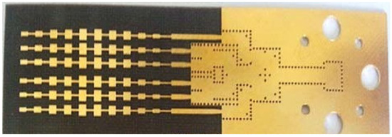
Figure 3.
Illustration of substrate-integrated-waveguide (SIW) based series fed microstrip array antenna at 77 GHz. (Reference [33]).
A novel planar grid antenna array with small loop elements operating in the automotive radar band of 77–81 GHz is presented [35]. The grid array provides improved beam scanning with a wide bandwidth of 4 GHz in E-band. This design was fully compliant with on-chip antennas, and it is verified experimentally. A planar antenna array was printed on an LTCC substrate for 77-GHz automotive LRR applications consisting of two transmitting and three receiving microstrip patch antennas. A broad band-width of 2 GHz and a gain of 27.1 dBi achieved with LTCC as a high substrate dielectric constant (εr = 7.54). The gain can be enhanced by adding a resistive metal sheet, thus, an unwanted ripple in the pattern can be reduced [36]. A new SIW based slot array is designed for both 77-GHz automotive MRR and LRR applications. A mixed optimization approach was introduced [37], which includes aggressive space mapping and non-linear fitting to achieve a flat shoulder radiation pattern. The experimental peak gain obtained for the array antenna is 21.7 dBi.
Low-cost automotive radar technology is still lacking, even if autonomous driving is pretty real. An electromagnetically coupled microstrip antenna array discussed with reduced mutual interference, enhanced impedance bandwidth, and gain. Besides, consistent radiation pattern among 10 dB return-loss bandwidth from 76 to 81.4 GHz [38]. A slotted SIW used as a feed for linear array patch antenna consisting of circular patches is designed for 77-GHz automotive radar applications. The proposed 1 × 8 linear, circular patch array antenna produces higher gain due to additional slots at the circular patch center. The performance of 4 × 8 planar arrays is also tested and validated by combining four 1 × 8 planar antenna arrays [39]. Distinct planar array antennas for transmission and reception are designed on a substrate consisting of an array column of 10 square patch elements that produces a fan beam, radiating widely in azimuth and narrows in elevation planes. A single circularly polarized wave is excited by the microstrip quadrature power-divider network, and the several array columns are organized parallel for digital beam-forming in the azimuthal plane. A prototype of receiving columns has been fabricated and measured at 78-GHz automotive radar frequency band [40].
A novel feed method of the double indirect-coupled structure is used for planar antenna arrays to achieve wide bandwidth and gain for automotive radar applications. A combination of a stripline, curved rectangular radiator, and a waveguide feed mechanism is used to design the planar antenna array. Further, to enhance the broad impedance matching and the gain, indirectly-coupled feed is used as the shift between the stripline and the waveguide feed structure [41].
The 77-GHz low-profile automotive radar planar antennas are presented in Table 4, with a view of the type of the antenna, feed configuration, frequency range, dielectric material properties, and specific application. The detailed performance parameters of the 77-GHz printed automotive radar antennas are presented in Table 5 by specifying the impedance bandwidth, gain, 3 dB beamwidth, cross-polarization, radiation efficiency, etc.
3. Sensors for Automotive Radar Technology
Automotive trucks and cars are installed with a distance sensor that perceives the distance among the vehicles or large entities opposite the vehicle. These sensors operate at 77 GHz and use another band of frequencies, such as 24 GHz, and 79 GHz is utilized by collision avoidance and adaptive cruise-control systems. Some autonomous vehicles use infrared sensor systems in addition to (or instead of) radar sensors [42]. Two important methods are used to measure the distance using radar. The first is called the direct propagation method, which measures the delay associated with the reflected signal’s reception. This delay can be related to the distance of the reflective object. The delay is related to the function of the light velocity and the period or to the propagation time of light transmission and reception. The second method is called the indirect propagation or Frequency-Modulated Continuous Wave (FMCW) method. For indirect propagation, sending, and receiving modulation frequencies, the frequency difference can be used to determine the distance and relative velocity of the object directly.
Sensors used to monitor vehicles’ driving environment embody critical technologies, Intelligent Transportation System (ITS). Sensing elements include ultrasonic sensors, image processing sensors, infrared lidar, microwave radar and, millimeter-wave radar. Compared with other types, the advantage of a millimeter-wave radar is that it can detect targets stably even in lousy weather conditions like rain or snow. Significant recent progress radio frequency technology promotes the production of high-quality products and highly efficient radar sensors. Therefore, millimeter-wave radar has been supplied as a vehicle collision warning sensor [43].
4. Challenges and Future Scope
The fundamental challenge in low-profile printed millimeter-wave automotive radar antennas is reducing sidelobe levels directly disturbing the gain and beam formation. Typical multi-beam or beam-scanning antenna requirements in a millimeter wave technology is the high gain that is up to 30 dBi and low to reasonable sidelobe levels. Generally, the loss is a very vital issue. When the planar approach is compared with a commercial dielectric lens, the planar elements possess expressively higher losses, particularly the beam-forming device. The planar antenna efficiency of the 77-GHz automotive radar system is around 50%—these losses due to conductor and dielectric materials. The antenna system’s overall size should be small to integrate into the automotive radar module of the autonomous vehicle. In addition, advanced sensors and smart metering systems would bring additional interesting features to these modern vehicles. Artificial intelligence and machine learning (AIML) tools are gaining wide range of attention in the industry in all the engineering domains. Therefore, integration of advanced sensor technology with AIML and deep learning techniques will foresee the potential future research on the advancements of the electrical vehicles and autonomous vehicles.
5. Conclusions
This work emphasized the key concepts of the autonomous vehicles concerning the power electronic converter topologies and communication aspects. In part 1 of this article, various convertor topologies and condition monitoring aspects concerning electric vehicles were enumerated and reported. In the present paper, recent developments and challenges of low profile 24- and 77-GHz printed antennas for automotive radar applications are reviewed and summarized. The design methodologies, feed techniques, and other antenna parameters (antenna type, frequency range, bandwidth, size, and intended application) are presented comprehensively concerning the available literature in the form of Table 2, Table 3, Table 4 and Table 5. The antenna performance concepts, like beam scanning techniques, gain, and cross-polarization levels, are discussed broadly. This paper’s qualitative and quantitative information is useful for engineers who are working on low-profile, printed 24- and 77-GHz automotive or anti-collision radar antennas.
Author Contributions
Conceptualization, N.K.D.; methodology, N.K.D.; validation, U.M.R. and A.K.V.; formal analysis, M.S.; resources, C.-W.P.; data curation, M.S.; writing—original draft preparation, N.K.D.; writing—review and editing, U.M.R.; supervision, I.F. All authors have read and agreed to the published version of the manuscript.
Funding
This research received no external funding.
Institutional Review Board Statement
Not applicable.
Informed Consent Statement
Not applicable.
Conflicts of Interest
The authors declare no conflict of interest.
References
- Gardill, M. Automotive Radar–A Signal Processing Perspective on Current Technology and Future Systems; Repositorio Institucional Universidad de Málaga: Málaga, Spain, 2018. [Google Scholar]
- Microwaves & RF, “Driving Safety with Automotive Radar Systems,” Microwave & RF. Available online: https://www.mwrf.com/technologies/systems/article/21849983/driving-safely-with-automotive-radar-systems (accessed on 9 March 2021).
- Viikari, V.V.; Varpula, T.; Kantanen, M. Road-condition recognition using 24 GHz automotive radar. IEEE Trans Intell. Transp. Syst. 2009, 10, 639–648. [Google Scholar] [CrossRef]
- Series, M. Systems characteristics of automotive radars operating in the frequency band 76–81 GHz for intelligent transport. systems applications. In Recommendation ITU-R, M.2057-1; International Telecommunication Union: Geneva, Switzerland, 2018. [Google Scholar]
- Balanis, C.A. Antenna Theory: Analysis and Design; John Wiley & Sons: Hoboken, NJ, USA, 2016. [Google Scholar]
- Bhartia, P.; Tomar, R.S.; Rao, K.V.S. Millimeter-Wave Microstrip and Printed Circuit Antennas; Artech House: Norwood, MA, USA, 1991. [Google Scholar]
- Carver, K.R.; Mink, J. Microstrip antenna technology. IRE Trans. Antennas Propag. 1981, 29, 2–24. [Google Scholar] [CrossRef]
- Xue, L.; Fusco, V. 24 GHz automotive radar planar Luneburg lens. IET Microw. Antennas Propag. 2007, 1, 624–628. [Google Scholar] [CrossRef]
- Alhalabi, R.A.; Rebeiz, G.M. High-Efficiency Angled-Dipole Antennas for Millimeter-Wave Phased Array Applications. IEEE Trans. Antennas Propag. 2008, 56, 3136–3142. [Google Scholar] [CrossRef]
- Alhalabi, R.A.; Rebeiz, G.M. High-Gain Yagi-Uda Antennas for Millimeter-Wave Switched-Beam Systems. IEEE Trans. Antennas Propag. 2009, 57, 3672–3676. [Google Scholar] [CrossRef]
- Lee, M.-S.; Kim, Y.-H. Design and Performance of a 24-GHz Switch-Antenna Array FMCW Radar System for Automotive Applications. IEEE Trans. Veh. Technol. 2010, 59, 2290–2297. [Google Scholar] [CrossRef]
- Ghaffar, F.A.; Khalid, M.U.; Salama, K.N.; Shamim, A. 24-GHz LTCC Fractal Antenna Array SoP with Integrated Fresnel Lens. IEEE Antennas Wirel. Propag. Lett. 2011, 10, 705–708. [Google Scholar] [CrossRef]
- Zhang, L.; Zhang, W.; Zhang, Y.P. Microstrip Grid and Comb Array Antennas. IEEE Trans. Antennas Propag. 2011, 59, 4077–4084. [Google Scholar] [CrossRef]
- Alsath, M.G.N.; Kanagasabai, M. Ultra-wideband grid array antenna for automotive radar sensors. IET Microw. Antennas Propag. 2016, 10, 1613–1617. [Google Scholar] [CrossRef]
- He, Y.; Ma, K.; Yan, N.; Wang, Y.; Zhang, H. A Cavity-Backed End-fire Dipole Antenna Array Using Substrate-Integrated Suspended Line Technology for 24 GHz Band Applications. IEEE Trans. Antennas Propag. 2018, 66, 4678–4686. [Google Scholar] [CrossRef]
- Hamberger, G.F.; Trummer, S.; Siart, U.; Eibert, T.F. A Planar Dual-Polarized Microstrip 1-D-Beamforming Antenna Array for the 24-GHz Band. IEEE Trans. Antennas Propag. 2016, 65, 142–149. [Google Scholar] [CrossRef]
- Kuo, C.-H.; Lin, C.-C.; Sun, J.-S. Modified Microstrip Franklin Array Antenna for Automotive Short-Range Radar Application in Blind Spot Information System. IEEE Antennas Wirel. Propag. Lett. 2017, 16, 1731–1734. [Google Scholar] [CrossRef]
- Yu, C.-A.; Li, E.S.; Jin, H.; Cao, Y.; Su, G.-R.; Che, W.; Chin, K.-S. 24 GHz Horizontally Polarized Automotive Antenna Arrays with Wide Fan Beam and High Gain. IEEE Tran. Antennas Propag. 2019, 67, 892–904. [Google Scholar] [CrossRef]
- Boyuan, M.; Pan, J.; Wang, E.; Luo, Y. Fixing and Aligning Methods for Dielectric Resonator Antennas in K Band and Beyond. IEEE Acces. 2019, 7, 12638–12646. [Google Scholar] [CrossRef]
- Ramasubramanian, K.; Ramaiah, K. Moving from legacy 24 GHz to state-of-the-art 77-GHz radar. ATZelektronik Worldw. 2018, 13, 46–49. [Google Scholar] [CrossRef]
- Menzel, W.; Pilz, D.; Al-Tikriti, M. Millimeter-wave folded reflector antennas with high gain, low loss, and low profile. IEEE Antennas Propag. Mag. 2002, 44, 24–29. [Google Scholar] [CrossRef]
- Schoebel, J.; Herrero, P. Planar Antenna Technology for mm-Wave Automotive Radar, Sensing, and Communications. Radar Technol. 2010. [Google Scholar] [CrossRef]
- Hallbjorner, P.; He, Z.; Bruce, S.; Cheng, S. Low-Profile 77-GHz Lens Antenna with Array Feeder. IEEE Antennas Wirel. Propag. Lett. 2012, 11, 205–207. [Google Scholar] [CrossRef]
- Menzel, W.; Moebius, A. Antenna Concepts for Millimeter-Wave Automotive Radar Sensors. In Proceedings of the IEEE; Institute of Electrical and Electronics Engineers (IEEE): Piscataway, NJ, USA, 2012; Volume 100, pp. 2372–2379. [Google Scholar]
- Hasch, J.; Topak, E.; Schnabel, R.; Zwick, T.; Weigel, R.; Waldschmidt, C. Millimeter-Wave Technology for Automotive Radar Sensors in the 77 GHz Frequency Band. IEEE Trans. Microw. Theory Tech. 2012, 60, 845–860. [Google Scholar] [CrossRef]
- Wang, X.; Stelzer, A. A 79-GHz LTCC Patch Array Antenna Using a Laminated Waveguide-Based Vertical Parallel Feed. IEEE Antennas Wirel. Propag. Lett. 2013, 12, 987–990. [Google Scholar] [CrossRef]
- Artemenko, A.; Mozharovskiy, A.; Maltsev, A.; Maslennikov, R.; Sevastyanov, A.; Ssorin, V. Experimental Characterization of E-Band Two-Dimensional Electronically Beam-Steerable Integrated Lens Antennas. IEEE Antennas Wirel. Propag. Lett. 2013, 12, 1188–1191. [Google Scholar] [CrossRef]
- Hallbjorner, P.; Cheng, S. Improvement in 77-GHz Radar Cross Section of Road Work Jacket and Side Screen by Use of Planar Flexible Retrodirective Reflectors. IEEE Antennas Wirel. Propag. Lett. 2013, 12, 1085–1088. [Google Scholar] [CrossRef]
- Yeap, S.B.; Qing, X.; Chen, Z.N. 77-GHz Dual-Layer Transmit-Array for Automotive Radar Applications. IEEE Trans. Antennas Propag. 2015, 63, 2833–2837. [Google Scholar] [CrossRef]
- Imbert, M.; Papio, A.; De Flaviis, F.; Jofre, L.; Romeu, J. Design and Performance Evaluation of a Dielectric Flat Lens Antenna for Millimeter-Wave Applications. IEEE Antennas Wirel. Propag. Lett. 2014, 14, 342–345. [Google Scholar] [CrossRef]
- Sönmez, N.T.; Tokan, N.T. Effects of anti-reflective coatings on scanning performance of millimetre-wave lenses. IET Microw. Antennas Prop. 2016, 10, 1485–1491. [Google Scholar] [CrossRef]
- Khan, O.; Meyer, J.; Baur, K.; Waldschmidt, C. Hybrid Thin Film Antenna for Automotive Radar at 79 GHz. IEEE Trans. Antennas Propag. 2017, 65, 5076–5085. [Google Scholar] [CrossRef]
- Xu, J.; Hong, W.; Zhang, H.; Wang, G.; Yu, Y.; Jiang, Z.H. An Array Antenna for Both Long- and Medium-Range 77 GHz Automotive Radar Applications. IEEE Trans. Antennas Propag. 2017, 65, 7207–7216. [Google Scholar] [CrossRef]
- Chipengo, U.; Krenz, P.M.; Carpenter, S. From Antenna Design to High Fidelity, Full Physics Automotive Radar Sensor Cor-ner Case Simulation. Model. Simul. Eng. 2018, 2018, 1–19. [Google Scholar] [CrossRef]
- Arnieri, E.; Greco, F.; Boccia, L.; Amendola, G. A Reduced Size Planar Grid Array Antenna for Automotive Radar Sensors. IEEE Antennas Wirel. Propag. Lett. 2018, 17, 2389–2393. [Google Scholar] [CrossRef]
- Salzburg, C.G.; Vaupel, T.; Bertuch, T.; Wilhelm, M.; Wichmann, T.; Alfageme, S.T. Feasibility of an automotive radar antenna at 77 GHz on LTCC substrate. IET Radar Sonar Navig. 2018, 12, 1172–1178. [Google Scholar] [CrossRef]
- Yu, Y.; Hong, W.; Zhang, H.; Xu, J.; Jiang, Z.H. Optimization and Implementation of SIW Slot Array for Both Medium- and Long-Range 77 GHz Automotive Radar Application. IEEE Trans. Antennas Propag. 2018, 66, 3769–3774. [Google Scholar] [CrossRef]
- Tian, H.; Liu, C.; Gu, X. Proximity-coupled feed patch antenna array for 79 GHz automotive radar. J. Eng. 2019, 2019, 6244–6246. [Google Scholar] [CrossRef]
- Xu, J.; Hong, W.; Jiang, Z.H.; Zhang, H. Low-Profile Circular Patch Array Fed by Slotted Substrate Integrated Waveguide. IEEE Trans. Antennas Propag. 2018, 67, 960–970. [Google Scholar] [CrossRef]
- Hamberger, G.F.; Späth, S.; Siart, U.; Eibert, T.F. A Mixed Circular/Linear Dual-Polarized Phased Array Concept for Auto-motive Radar—Planar Antenna Designs and System Evaluation at 78 GHz. IEEE Trans. Antennas Propag. 2019, 67, 1562–1572. [Google Scholar] [CrossRef]
- Yoo, S.; Milyakh, Y.; Kim, H.; Hong, C.; Choo, H. Patch Array Antenna Using a Dual Coupled Feeding Structure for 79 GHz Automotive Radar Applications. IEEE Antennas Wirel. Propag. Lett. 2020, 19, 676–679. [Google Scholar] [CrossRef]
- Meinel, H.H.; Dickmann, J. Automotive radar: From its origins to future directions. Microw. J. 2013, 56, 24–40. [Google Scholar]
- Shinichi, H.; Uehara, N. Millimeter-wave radar technology for automotive application. Signal 2001, 1, b2. [Google Scholar]


Publisher’s Note: MDPI stays neutral with regard to jurisdictional claims in published maps and institutional affiliations. |
© 2021 by the authors. Licensee MDPI, Basel, Switzerland. This article is an open access article distributed under the terms and conditions of the Creative Commons Attribution (CC BY) license (http://creativecommons.org/licenses/by/4.0/).