Abstract
A theoretical model was developed to investigate a falling-film absorber on horizontal tubes with an aqueous alkaline nitrate solution as working fluid. The absorbent, composed of an aqueous solution of nitrates (Li, K, Na) in salt mass percentages of 53%, 28%, and 19% respectively, offers favourable thermal stability, corrosiveness, and heat and mass transfer conditions which can be appropriate for absorption cooling cycles driven by high-temperature heat sources. The mathematical model developed characterises the heat and mass transfer processes and the flow regime effect (droplet-formation, droplet-fall, and falling-film) on the falling-film absorber. The results show the importance of the falling-film and droplet-formation flow regimes in the absorption process. The solution temperature and concentration profiles inside the absorber were established together with their values at the exit. The results obtained by the theoretical model were well in agreement with the experimental data obtained by the authors in a previous study. Deviations in predicting the solution and cooling water temperatures at the absorber exit were around 1 °C and for the concentration of the solution leaving the absorber, around 0.49%. The mathematical model also predicts the absorption rate at 4.7 g·m−2·s−1 for the absorber design and operating conditions used in the present work. This value is 22% higher than the experimental value obtained by the authors in their previous experimental work. The deviation is attributed to approximations incorporated into the model, especially as regards surface wettability and calculation of the mass transfer coefficients for each flow regime.
1. Introduction
The most common configuration used in the absorber of absorption cooling systems is that of falling-film on horizontal tubes. The absorbent solution entering the absorber is distributed over the tubes via the solution distributor. A thin solution film falls over the external surface of the horizontal tubes and absorbs the refrigerant vapour. Absorption heat is released by cooling water flowing inside the tubes. Absorption cooling systems are environmentally appropriate alternatives to the vapour compression systems for space conditioning and can achieve high coefficients of performance (COP) when multi-effect configurations of the cycle are used. However, the success of this technology depends on the development of compact and high-performance heat and mass exchangers which, in turn, depend on the processes of heat and mass transfer with a phase change, and on the working fluid [1].
Several theoretical and experimental investigations in the literature are focused on the absorption process and the development of optimal designs. Amaris et al. [2] reviewed the experimental studies dealing with the enhancement of vapour absorption processes in absorbers employing passive techniques such as advanced surfaces, additives, and nanofluids. This review included an exhaustive and detailed scrutiny of the absorption process with different configurations of the absorber and different working fluids. The authors documented experimenting techniques, operating conditions, and the latest advances in terms of heat and mass transfer enhancement in absorbers.
However, the detailed analysis of heat and mass transfer processes in horizontal tube falling-film absorbers is complex. The operation of these absorbers depends on many parameters, such as the thermodynamic and transport properties of the working fluid, the operating conditions, the design parameters, i.e., diameter, number, and length of the tubes, and the surface wettability, among others.
The development of mathematical models that describe the absorption process in falling-film absorbers has been the objective of numerous theoretical investigations. Killion and Garimella [3] conducted a review on mathematical models that had been used to describe the simultaneous heat and mass transfer processes in horizontal tube falling-film absorbers. In the simplest models of this type of absorbers, the film formation is assumed to be in a laminar flow regime. This flow regime is developed at Reynolds numbers below 200, while a completely turbulent regime is evidenced at Reynolds numbers above 1600 (Killion and Garimella [3], Grossman [4]). The results obtained by these models are not precise, due to simplified assumptions made to determine the heat and mass transfer coefficients. Moreover, a series of instabilities cause the deviation of the falling-film flow from the laminar behaviour, even at low flow rates. For this reason, many investigations contemplated a turbulent flow regime for the falling-film. Recent studies have shown various flow structures, such as droplet formation, release, and impact, and film waves, any or all of which may affect the distribution of the liquid and, consequently, heat and mass transfer (Nagavarapu and Garimella [1], Killion and Garimella [5], Bustamante and Garimella [6], and Bohra et al. [7]).
Nagavarapu and Garimella [1] developed a heat and mass transfer model for falling-film ammonia-water absorption over horizontal microchannel tubes. The model was validated using experimental data. Three regions in the absorber were considered for vapour absorption, namely, the solution pool, evolving droplets, and falling-film. The authors concluded that vapour absorption occurs mainly in the film region, and up to 7% of the absorption rate takes place in the droplets. Heat transfer coefficients were estimated in the film region, and an empirical correlation was developed for the film Nusselt number.
In experiments, using a high-resolution video, Killion and Garimella [5] investigated the phenomenon of droplet formation in a water/LiBr falling-film absorber. The experimental absorber was formed by a single column of nine internally cooled tubes. The authors described the characteristic droplet evolution pattern, including axial elongation along the tube, the formation of a primary droplet, trailing liquid thread, and satellite droplets, and the formation of saddle waves caused by the spreading lamellae of the primary droplet impacts. This information is valuable for modelling the absorption process in horizontal tube banks as well as for validating computer models of droplet formation.
Bustamante and Garimella [6] studied the effect produced by the design of the flow distributor used in horizontal tube banks of falling-film heat and mass components. Flow configurations generated by the distributor, from droplet to sheet regimes, droplet surface areas and volumes, and jet diameters, were all measured using high-speed videos. The authors observed significant maldistribution (>50%) for some flow rates in all the designs tested.
Bohra et al. [7] investigated flow patterns on a horizontal-tube falling-film absorber of an ammonia-water absorption system. High-speed videos showed the droplet model to be the dominant inter-tube flow mode at the operation conditions of their experiments. However, droplet characteristics and flow transition depend strongly on the solution flow rate.
Some investigations have focused on hydrodynamics in falling-films and incorporated the analysis of heat and mass transfer (Kirby and Perez Blanco [8], and Jeong and Garimella [9]).
Vertical falling-film absorbers were used in most of these falling-film absorber models (Wassenaar and Westra [10], Patnaik and Perez-Blanco [11], and Patnaik et al. [12]), together with water/LiBr as the working pair.
When non-volatile absorbents, such as LiBr, are used and nonabsorbable gases are not present in the absorber, the vapour phase is formed only by the pure refrigerant, and this implies that there is no resistance to mass transfer in the vapour phase. Heat and mass transfer in a differential control volume can be described by the equations of energy and mass conservation balances applying in two spatial dimensions and one time dimension. The coupling of the equations of heat and mass transfer is conducted through the boundary conditions at the interface between the liquid and the vapour [3]. In most cases, the researchers assume that the liquid–vapour equilibrium prevails at the interface.
The review, reported by Bohra et al. [7], showed that the study of flow patterns and heat and mass transfer in falling films on tube bundles has been conducted mainly on individual tube column geometries in adiabatic conditions. The few studies that address the coupled mechanisms of heat and mass transfer are restricted to the working fluid water/LiBr. Different theoretical models of falling-film on horizontal tubes were developed to predict the performance of the absorber. Seewald and Perez-Blanco [13] considered the formation of three flow regimes in falling-film absorbers and developed a spiral absorber model that took into account the droplet-formation regime.
Killion and Garimella [3] highlighted the models that describe heat and mass transfer processes in falling-film absorbers assuming the heat and mass transfer coefficients. These semi-empirical models allow for some assumptions to be made on the hydrodynamics of the falling-film and provide reasonable results due to the appropriate representation of physical phenomenon.
Kirby and Perez-Blanco [8] developed a model for simultaneous heat and mass transfer processes occurring in a horizontal tube falling-film absorber using water/LiBr as a working fluid. Their absorber consisted of a bundle of 6 coolant tubes per row, where the cooling water and solution circulated in a counter-current direction. The operating conditions used in the model were those of commercial absorption chillers, i.e., absorber pressure 5.75–7.00 mmHg, solution inlet concentration 60–62 wt%, and Reynolds number 13–98. The absorber was divided into three flow regimes, namely, (i) droplet-formation flow, (ii) droplet-fall flow, and (iii) falling-film flow, considering non-wavy-laminar falling-film, complete wetting of the tubes, and droplet flow mode between tubes. The model used empirical heat and mass transfer coefficients and incorporated the effect of the flow regimes that the solution experiences as it flows down through the tube bundle. The model was validated using experimental data published by Nomura et al. [14] and was well in agreement.
Jeong and Garimella [6] developed a model for a water/LiBr horizontal tube absorber to predict heat and mass transfer performance in falling-film and droplet mode flow regimes. The absorber configuration consisted of a bank formed by 13 horizontal tubes in counter-current flow. The model was also validated using the experimental data reported by Nomura et al. [14]. The effect of incomplete wetting was dealt with by introducing the wetting ratio defined as the ratio between the wettened and total areas. The authors concluded that vapour was mainly absorbed in the falling-film and droplet-formation flow regimes, that heat and mass transfer in the free-fall flow regime was negligible, and that the wetting ratio had a significant effect on the absorber performance.
Juarez-Romero et al. [15] developed a computational model to characterize heat and mass transfer in a horizontal tube falling-film absorber integrated into a heat transformer used for water purification. The absorber consisted of a bundle of 16 tubes (4 per row) internally heated by the water to be purified. The absorber was designed to supply heat at high temperature for water purification. The model was validated using data reported by Holland et al. [16] and contemplated the flow regimes proposed by Kirby and Perez-Blanco [8]. It correctly predicted solution and heating water temperature profiles along the absorber.
Furthermore, it is well-known that the conventional working fluid water/LiBr cannot satisfactorily reach the operating conditions required in advanced configurations of absorption cooling cycles driven by high-temperature heat sources. Hence, several investigations have been conducted to identify other possible absorbents, capable of operating at high temperatures. The ternary solutions of alkaline nitrates (LiNO3 + KNO3 + NaNO3, in the mass ratio 53:28:19), known as Alkitrate and originally proposed by Davidson and Erickson [17], have appeared as a possible substitute to the conventional working fluid water/LiBr. They make better use of high-temperature heat sources, without presenting any corrosion or thermal stability issues. Álvarez et al. [18] investigated a triple-effect absorption cooling cycle called “the Alkitrate topping cycle” using aqueous nitrate solution as a working fluid. The coefficient of performance (COP) of this cycle was higher than that of a water/LiBr triple-effect absorption cycle at heat source temperatures over 180 °C. The Alkitrate cycle represents a relevant alternative to capitalize on the thermal potential of high-temperature heat sources. Hence, it is of great importance to investigate absorber performance at unusual operating conditions, at which conventional working fluid water/LiBr does not prove viable because it is subject to corrosion and thermal instability.
The objective of the present work is to develop a simplified model for a falling-film absorber on horizontal tubes in order to provide additional information that could help with a better understanding of the absorption process of the alkaline nitrate solution LiNO3 + KNO3 + NaNO3 used as a working fluid and applied in the mass proportions 53:28:19, respectively. The absorber operating conditions are those of the last stage of a triple-effect absorption cycle powered by high-temperature heat sources. The model facilitates the study of heat and mass transfer processes, and the effect of flow regimes that characterize falling-film absorbers. Therefore, this model is a useful tool for investigating absorber performance versus solution and cooling water operating conditions as well as the geometrical parameters of the absorber. The theoretical model developed in the present work is based on the investigations conducted by Juárez-Romero et al. [15] and Kirby and Perez-Blanco [8] and was validated with experimental data obtained by the authors in a previous study [19]. The governing equations, assumptions, solution methodology, and results are presented herein.
2. Operating Conditions of the Falling-Film Absorber
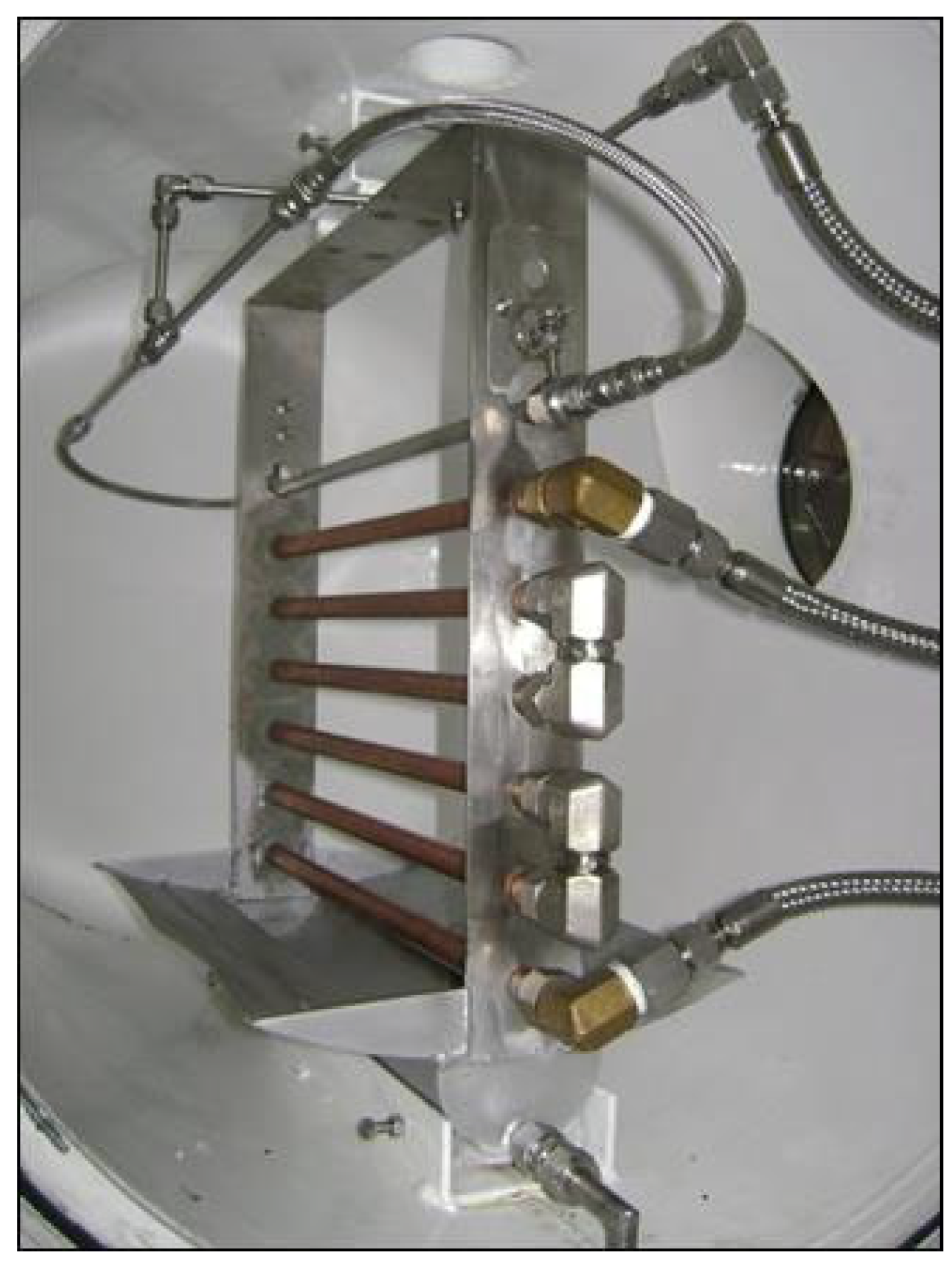
The water vapour (refrigerant) absorption process in a falling-film of an aqueous alkaline nitrate solution (absorbent) is investigated in the present work. The absorber configuration is based on a previously designed and built experimental prototype [20] and is shown in Figure 1. The design of this absorber was conducted under the operating conditions established by Álvarez et al. [18] for a triple-effect absorption cooling cycle.
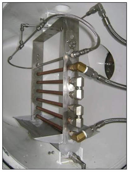
Figure 1.
Horizontal tube falling-film absorber built to investigate the absorption process with alkaline nitrate solution [19,20].
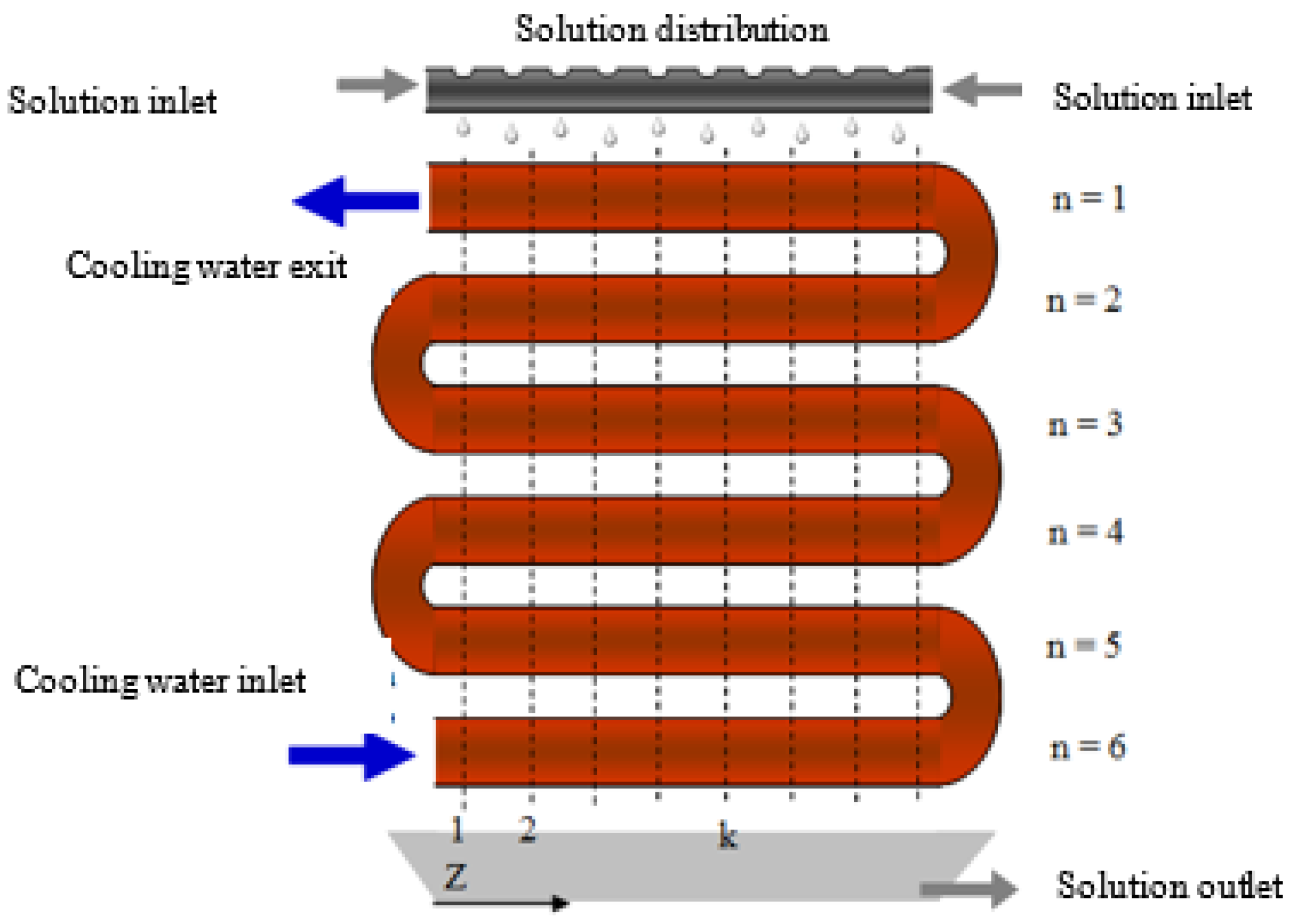
The absorber is made up of a cylindrical chamber that contains a bundle of six copper tubes in line and connected in series, a solution distributor at the inlet, and a solution collector tray at the outlet of the absorber. The alkaline nitrate solution circulates over the external surface of the tubes from the top to the bottom of the absorber, creating the falling-film, and it makes contact with the vapour coming from a water vapour generator. At the outlet of the absorber, there is a more diluted solution flow than that at the inlet because the solution has absorbed the water vapour. Figure 2 presents a schematic diagram of the absorber and flow configurations. The falling-film formed on the external surface of the tubes of the absorber is cooled down by the water that flows through the tubes that make up the absorber, and in a counter-current direction to the solution flow. The objective of the cooling water is to dissipate the heat released during the absorption process, thus, maintaining the driving potential for mass transfer.
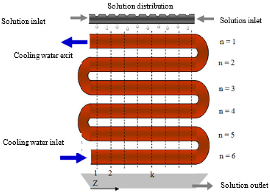
Figure 2.
Schematic diagram of the horizontal tube falling-film absorber.
The operating conditions considered in the present work were obtained from those used in a previous experimental investigation carried out by the authors on the same absorber [19]. This experimental work consisted mainly of a sensitivity study of the absorber operating variables and took into account a series of absorber efficiency parameters, such as absorption rate, thermal load, solution concentration difference between the entrance and exit of the absorber, subcooling degree of the solution leaving the absorber, and heat and mass transfer coefficients. Data obtained from the experimental work were used to validate the mathematical model for the falling-film absorber developed in the present work.
Table 1 and Table 2 summarize, respectively, the absorber geometric parameters and the inlet operating conditions used for the absorber model. A base mass concentration of 82% for the nitrate solution and an absorber operation pressure of 30.0 kPa were selected. The cooling water temperature and the solution flow rate at the inlet of the absorber were varied in order to study their effect on the absorber performance and the validity of the model to predict outlet operating conditions.

Table 1.
Geometrical parameters of the different components in the absorber.
Table 2.
Operating conditions used in modelling the horizontal tube falling-film absorber.
It is important to note that, in order to study the effect of each variable, the rest of the operating conditions were maintained constant. However, some variables of the study are closely related. Therefore, certain criteria were established that permitted comparison between the different tests carried out at the same operating condition baseline. The temperature and concentration of the solution at the inlet of the absorber influence the absorption process, since they determine deviation with regard to equilibrium, and this affects the driving force for heat and mass transfer processes, as well as the thermodynamic and transport properties of the solution. It is worthy of note that when the solution is subcooled to a high degree when it enters the absorber, it enhances mass transfer at the absorber entrance.
3. Mathematical Modelling of the Absorber
In the absorber, the falling-film is formed on the external surface of each tube and this is sustained by the continuous flow of solution that comes in through the top part of the absorber and falls due to gravity. The cooling water that circulates inside the tubes of the absorber is perpendicular to the flow of the solution; therefore, the model developed is two-dimensional (2D).
Moreover, the falling-film experiences changes in the flow configuration when the solution flows from one tube to another. When droplets are formed, the surface of the exposed solution increases, whereby the available area for mass transfer increases and, consequently, improves vapour absorption [21].
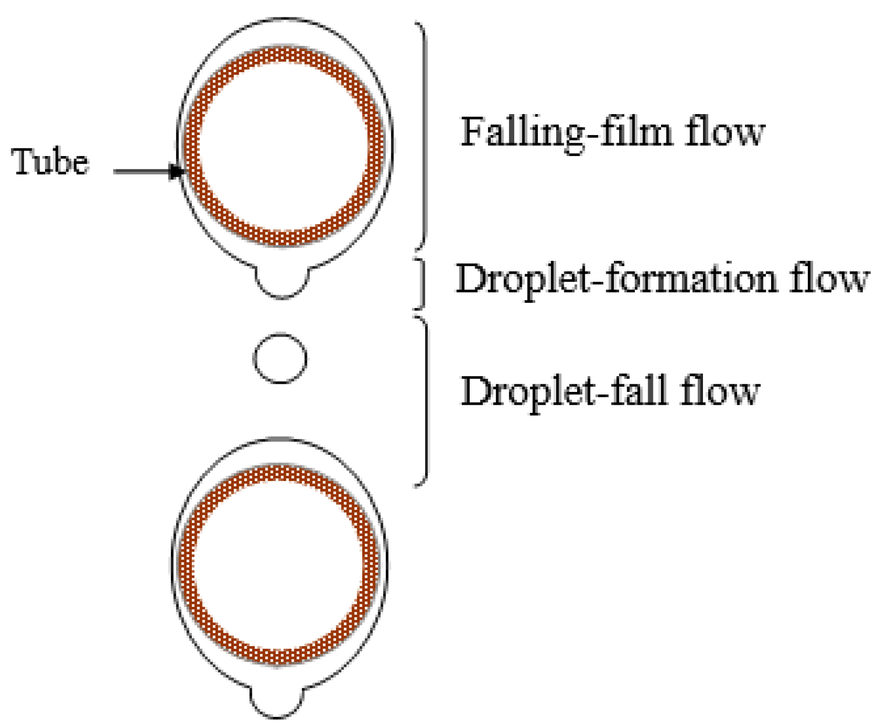
The three flow regimes that are present in the falling-film absorber on horizontal tubes (see Figure 3) are [8]:
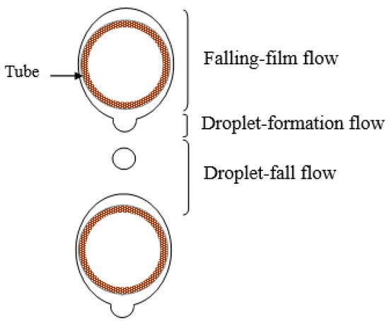
Figure 3.
Flow regimes in horizontal tube falling-film absorbers.
- Falling-film flow regime, which occurs on the external surface of each tube.
- Droplet-formation flow regime, which occurs at the bottom of each tube.
- Droplet-fall flow regime, extending from one tube until it reaches the next one.
The falling absorbent solution experiences each one of these flow regimes successively as it flows from one tube to the other. The mathematical model developed here integrates these different flow regimes into mass and energy balances and these are used to describe the absorption process of the absorber.
It is important to highlight that the flow regime, i.e., droplets, columns, and leaves, that describes the flow of the solution on the tubes of the absorber, is dependent on the solution mass flow rate (Γ). In most absorbers, the solution mass flow rate is controlled so as to achieve droplet formation between tubes.
The average volume of the droplets formed on the bottom part of each tube is described by the following expression [22]:
where Vdroplet is the average droplet volume, g is the gravity constant, and σ and ρ are the surface tension and the density of the solution, respectively.
Moreover, Hu and Jacobi [23] suggested that when the solution film flows between the tubes in a droplet flow regime, the value of the Reynolds number of the film is lower than the value obtained from the following Equation:
where modified Galileo dimensionless number (Ga) is defined as:
where is the dynamic viscosity of the solution.
In another study, Hu and Jacobi [24] proposed the following expression for the average distance between the nucleus of solution droplet formations (DND) (see Figure 3):
where do is the external diameter of the tubes, and ξ is the length of the capillary tube defined by the following expression:
3.1. Residence Time
Due to the differences in the transport phenomena produced during the absorption process, the residence time of the solution in each flow regime is an important parameter in absorber modelling. Firstly, the average residence time of the solution in the droplet-formation flow regime is calculated from the following Equation [8]:
where mdroplet is the droplet mass, Γ is the solution flow divided by twice the length of the tube, and N is the number of droplets per unit of length of the tube. The number of droplets can be calculated from the following Equation [8]:
N = 1/DND
Residence time in the droplet-fall flow regime, tfall, is calculated using a simple freefall expression [8]:
where ST is the distance between the tubes, and g is the gravity constant.
In the falling-film flow regime, the residence time of the solution can be calculated from the rate of descent and the film thickness. Assuming that the falling-film flow is laminar, Nusselt’s equation is applied for the film thickness, δ:
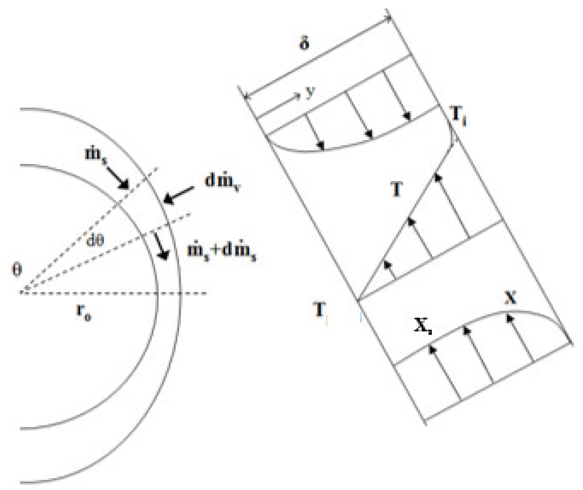
where θ (in rad) is the angle describing the solution film in relation to the centre of the tube (see Figure 4). The descent velocity of the film (u) is calculated with the following expression:
where δ is the film thickness.
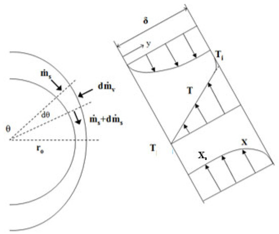
Figure 4.
Control volume used in heat and mass transfer balances in the falling-film [9].
The total residence time of the falling-film (tfilm) is defined by the following Equation [8]:
In the equation above, ro is the external radius of the absorber tubes.
3.2. Governing Equations for the Different Flow Regimes
The Equations that describe each one of the flow regimes were developed by Kirby and Perez-Blanco [8] and Juárez-Romero et al. [15]. Below, the governing equations for each one of the three solution flow regimes are presented.
3.2.1. Droplet-Formation Flow Regime
This flow regime takes place at the bottom of each tube. The droplet formation process is complex, and the most difficulty is encountered in defining the interface conditions of the droplet when its formation occurs. In this study, the equations describing heat and mass transfer of the droplet-formation flow regime are based on the assumption of a “fresh” surface [25] that permits the identification of interface conditions during this regime. In this manner, it is assumed that the droplet is formed by a successive series of thin spherical layers [8]. The fresh or new solution that joins the droplet forms a thin spherical layer on top of the bulk of the old solution. In addition, the droplet formation process is assumed to be adiabatic. Below are the expressions for the mass and energy balance equations.
Mass balance: the flow of absorbed vapour in this regime is calculated from the following expression:
where, kform is the mass transfer coefficient for the droplet-formation flow regime, rdroplet is the radius of the droplet, Xs is the mass concentration of the solution coming from the falling-film, and Xi is the mass concentration at the interface, both in % of the absorbent. The interface conditions are calculated assuming that the temperature at the interface is the same as the temperature of the film that will form the new droplet. The interface concentration is obtained from the liquid–vapour equilibrium:
Once the vapour absorption flow rate has been defined, the final droplet mass is calculated by adding the calculated flow of absorbed vapour to the initial droplet mass.
Energy balance:
where Q is the heat transferred from the nucleus of the old and hot droplet to the new and cooler spherical layer, and qabs is the absorption heat. The interface condition of each new layer is calculated assuming that the temperature of the droplet interface is always the same as the temperature of the fresh solution that forms the droplet. Afterwards, it is assumed that the superficial layer adheres to the droplet and forms the nucleus.
The absorption heat, qabs, and the heat, Q, are calculated as follows (Juárez-Romero et al. [15]):
where hv and hs are the specific enthalpy of saturated vapour and the specific enthalpy of the solution respectively, and λs is the thermal conductivity of the solution. The thermophysical properties (ρ, µ, Cp, h, λ, σ) of the alkaline nitrate solution were taken from the experimental database and empirical correlations obtained by Alvarez [20] from the literature.
3.2.2. Droplet-Fall Flow Regime
In the droplet-fall flow regime, the heat and mass transfer equations as well as the mass and energy balances applied to a droplet [8] are written in the same way as in the droplet-formation flow regime. In this model, the effects of any internal circulation that may occur inside the droplet are not considered. Most falling-film absorbers on horizontal tubes have a small spacing between the tubes, so the falling time of the droplets is short, and consequently, the effect of the internal circulation inside the droplet is reduced [8]. The governing equations are described below:
Mass balance:
Energy balance:
where kfall is the mass transfer coefficient in the droplet-fall flow regime, Xs and Xi are the absorbent concentrations in the bulk of the solution and at the interface respectively, and qabs is the heat absorption.
In order to calculate the interface conditions of the droplet, a linear temperature profile is assumed in the case of this flow regime, since the residence time of the droplets in the spacing between the tubes is short, and the relative importance of this flow regime does not justify a more complex model [8]. This linear temperature profile is defined as:
Equation (19) and the concentration–temperature relation at the interface (Equation (13)) define the interface conditions in this regime.
3.2.3. Falling-Film Flow Regime
In the falling-film flow regime, the heat and mass transfer equations and mass and energy balances applied to a thin film surrounding the horizontal tube are written as follows [8]. The energy balance is performed both on the solution side and on the cooling water side.
Energy balance (solution side), assuming a stationary state:
Energy balance (cooling water side):
where ms is the mass flow rate of the solution, mc is the mass flow rate of the cooling water, U is the overall heat transfer coefficient, Cpc is the specific heat of the cooling water, and z and θ are the horizontal and angular coordinates of the absorber (see Figure 2 and Figure 4), respectively.
In Equation (21), the overall heat transfer coefficient, U, is calculated using the following expression:
where hs and hc are the heat transfer coefficients of the falling-film and the cooling water respectively, λCu is the thermal conductivity of copper (396.4 W·m−1·°C−1), and do and di are the external and internal diameters of the tubes, respectively.
The Nusselt number and the heat transfer coefficient (hc) on the cooling water side were calculated using the Dittus-Boelter correlation, which is appropriate for turbulent flow in tubes:
where λc is the thermal conductivity of water (0.67 W·m−1·°C−1), and Prc is the Prandtl number of water.
The heat transfer coefficient for the falling-film solution, hs, was obtained by Alvarez et al. [26] by means of the artificial neural network methodology. The resulting equation uses 6 variables, namely, absorber pressure (Pabs), solution temperature at the inlet of the absorber, cooling water temperature at the inlet (Tc,in), solution mass concentration at the inlet of the absorber (Xs,in), mass flow of cooling water (mc), and solution mass flow rate per tube length (Γ). A root mean square error (rmse) of 1.183 was attained on prediction of the convective coefficient, hs.
where I and J are the numbers of inputs (I = 6) and neurons in the hidden layer (J = 9); IW and LW are the weight matrices in the hidden and output layers, respectively. Pi is the input “i” normalized, and b1 and b2 are the bias vectors in the hidden and output layers, respectively.
A learning model was applied by Alvarez et al. [26] using the performance parameters for the horizontal falling-film absorber. They obtained the best adjustment in weights (IWj,i and LWk,j) and biases (b1j and b2k) for the neural network structure formed by a one-layered neural network with 9 neurons in the hidden layer.
Because of the differences in hydrodynamics of each region, each one of the flow regimes considered in the model must be characterized by a different mass transfer coefficient. In this study, empirical mass transfer coefficients were not obtained for each one of the flow regimes, however, the approach reported by Jeong and Garimella [9] was used for the calculation of these mass transfer coefficients.
Moreover, Andberg and Vliet [27] also proposed the use of a linear temperature profile in the solution film. Therefore, a linear temperature profile is assumed (Equation (25)) to calculate the interface conditions in this flow regime.
Mass balance (solution side):
The amount of vapour absorbed at the interface is determined by the following Equation:
where kfilm is the mass transfer coefficient for the falling-film regime, and Xs and Xi are the concentrations in % in the bulk of the solution and at the interface, respectively.
Jeong and Garimella [9] detailed the investigation presented by Skelland and Minhas [28], in which they compared mass transfer coefficients for the droplet-formation flow regime, reported by different researchers and then proposed the following generic Equation:
where D is the mass diffusivity of the solution, tform is the residence time in the droplet-formation flow regime, and C2 is a constant. Heertjes et al. [29] suggested a C2 value equal to 24/7 for the cases in which the droplet-formation is fast (tform lower than 1.05 s). In addition, the fast formation of droplets facilitates internal circulation, and therefore, diffusion velocity is lower than droplet growth velocity [9]. In this study, tform is lower than 1.5 s, and that is why the C2 constant suggested by Heertjes et al. [29] was considered appropriate.
Jeong and Garimella [9] also recommended the mass transfer coefficient proposed by Clift et al. [25] for the droplet-fall flow regime:
where D is the mass diffusivity coefficient of the solution, and ddroplet is the droplet diameter.
For the falling-film flow regime, the mass transfer coefficient can be calculated using the film theory suggested by Whitman [30] in the following expression [9]:
where D is the mass diffusivity coefficient of the solution and δ is the thickness of the falling-film.
3.3. Assumptions
To develop the differential equations that describe the dynamic behaviour of an absorption process in a falling-film absorber on horizontal tubes, the following assumptions and equilibrium considerations were taken into account [15]:
- Absorption process in the tube bundle is described using a bi-dimensional approach (2D).
- Working fluid is Newtonian and the solution flow is laminar.
- Absence of non-condensable gases in the vapour phase.
- Pressure drop in the absorber is insignificant.
- Heat transfer from the absorbent solution to the vapour is insignificant, hence heat transfer on the vapour side is negligeable for the three flow regimes.
- Absorbent solution completely covers the tube surface, that means wetting of the tubes is perfect.
- Tubes have a smooth surface.
- Thermodynamic and transport properties depend on the temperature and concentration conditions (T, X) at each step of the calculation sequence.
- Liquid–vapour equilibrium is assumed to be present at the interface.
- Mass transfer coefficients for each flow regime are obtained from the correlations proposed by Jeong and Garimella [9].
- Mass diffusivity coefficient, D, is approximated to the mass diffusivity of the LiBr aqueous solution proposed by Wike-Chang [31].
4. Calculation Procedure
The model employed for horizontal tubes falling-film absorbers assumes that the tubes are divided into several segments over which the solution film falls (see Figure 2). The calculation code was developed in the Matlab® program environment and based on the calculation sequence reported by Juárez-Romero et al. [15] and Kirby and Perez-Blanco [8]. The resolution procedure for the ordinary differential equations, which govern the 2D behaviour of the absorber, used the Runge-Kutta fourth-order method. The equations governing each one of the three flow regimes were combined to model the whole absorber. In addition, the integration of the flow regions in the absorber was achieved by making the solution flow and the inlet and outlet conditions coincide when the solution goes from one regime to the next.
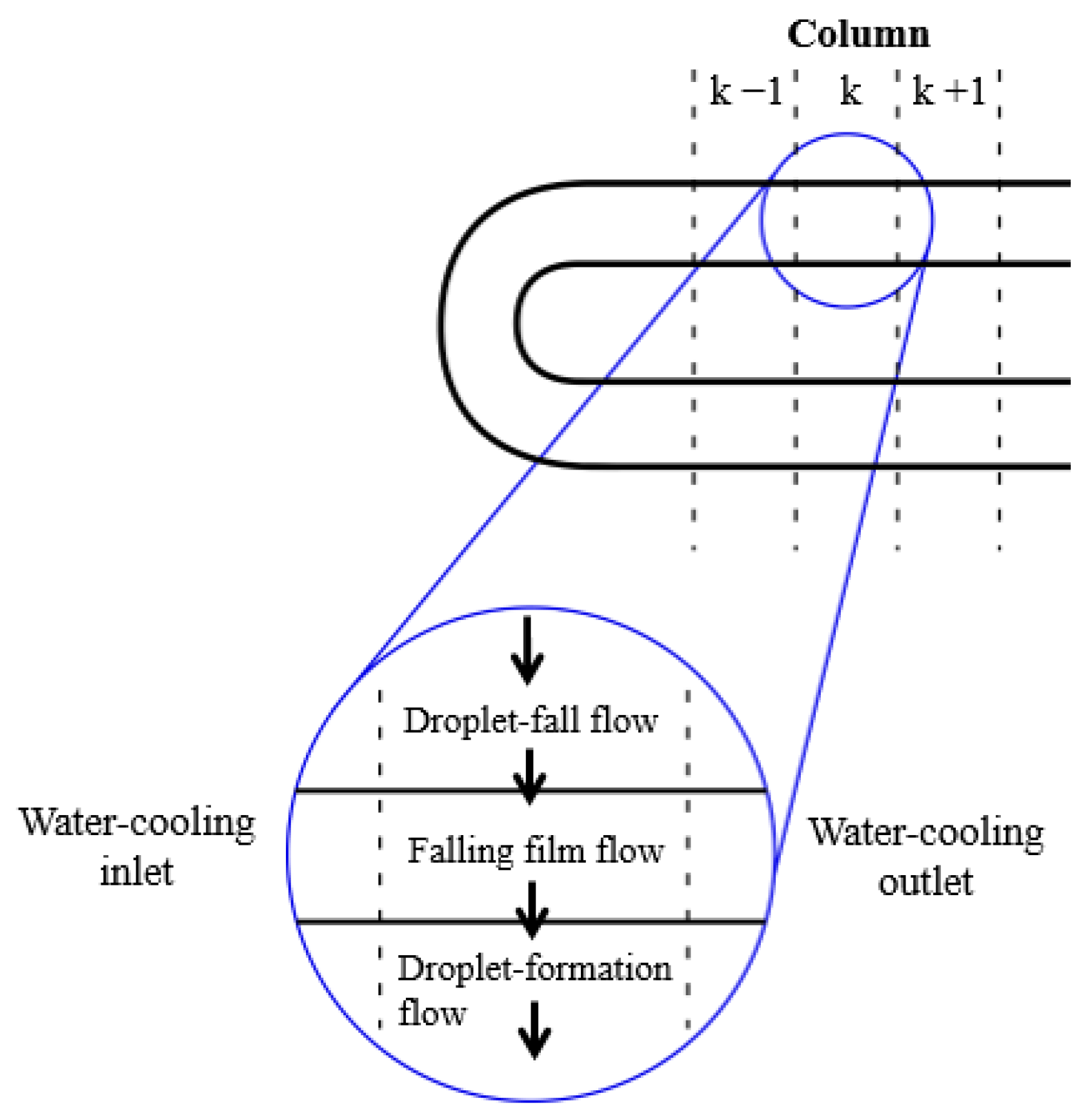
In order to solve the governing equations, the absorber was divided into different segments (see Figure 5). All flow regimes considered, i.e., droplet-formation flow, droplet-fall flow, and falling-film flow, take place in each segment. The absorbent solution flows from the top section of each segment to the bottom, while the cooling fluid flows horizontally.
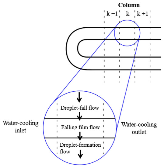
Figure 5.
k-th element of the physical model [8].
The calculation code requires the following input data: inlet temperatures of the solution and cooling water, solution mass flow rate, absorber operating pressure, inlet concentration of the solution, and certain absorber design parameters, such as tube number, tube diameter, tube length, and spacing between tubes. The equations were solved step by step for each segment of the absorber. The solution and cooling water conditions of each segment were used to connect the absorber segments to those precedent and adjacent to them.
The solution flows from row to row, combining the conditions of the absorbent solution, leaving the top segment with the solution entering into the bottom segment. When the energy and mass balances for each flow regime in each segment are performed, the whole calculation sequence is applied to the next segment. In this way, the solution properties resulting from the flow over the segments of the upper tube are used as inlet solution properties for the corresponding segments of the next tube. Additionally, the cooling water conditions are coupled with the adjacent segments. The calculations are repeated for each tube segment so that the properties of the solution at the outlet are determined. The calculation sequence of the model is illustrated in Figure 6.
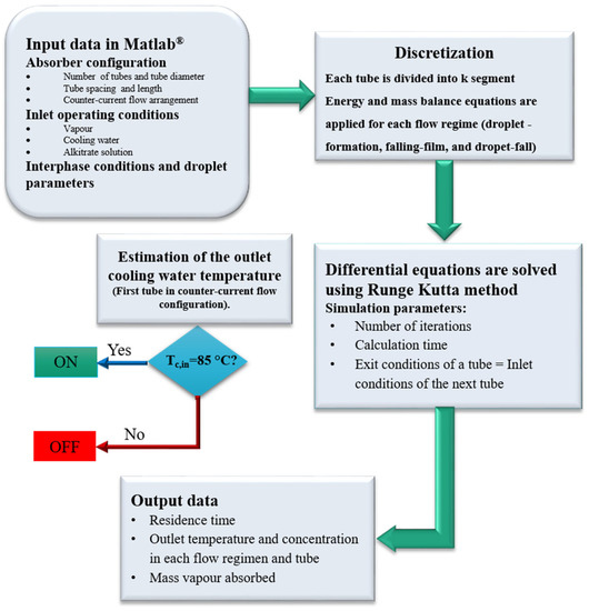
Figure 6.
Calculation sequence of the model.
It is worthy of note that experimental data available was limited to cooling water temperature, and solution temperature and concentration at the inlet and outlet of the absorber. Therefore, it was not possible to validate local profiles of the solution temperature and concentration along the tube bundle.
5. Results and Discussion
5.1. Effect of the Solution Flow Regimes
The three solution flow regimes reported by Kirby and Perez-Blanco [8] were considered: the droplet-formation flow regime in the lower part of each tube, the droplet-fall flow regime between the tubes, and the falling-film regime on the external surface of each tube. The solution flow at the inlet of an absorber is usually controlled in a manner that allows for a droplet-formation flow regime between the tubes. Thus, the operating conditions at a solution mass flow rate of 0.018 kg·m−1·s−1 were selected for the absorber. This solution mass flow rate was selected because an appropriate droplet-formation (without the presence of a column or liquid bridges), as well as an appropriate wetting of the tubes, was observed by Álvarez and Bourouis [19] in their previous experimental work. The authors observed that at higher mass flow rates, columns of liquid were formed. These affected heat and mass transfer, and the assumptions considered in the model regarding the droplet-formation flow regime lost its validity. In addition, the mathematical model was validated and compared using experimental data obtained with the setup built to investigate the absorption process [19].
Table 3 shows the average residence time for each flow regime. As can be observed, the average residence time of the droplet-fall flow regime is considerably shorter than the residence times of the other two flow regimes, and consequently, this regime contributes less to heat and mass transfer. In contrast, the average residence time of the falling-film flow regime is almost twice that of the droplet-formation flow regime.
Table 3.
Average residence time for each flow regime in the horizontal tube falling-film absorber using aqueous alkaline nitrate solution as a working fluid.
For the model developed in the present work, the spacing between the droplets, λ, was estimated at 20.9 mm, and the capillary length, ξ, at 2.5 mm. Jeong and Garimella [9] reported values of 18 and 2.4 mm, for λ and ξ respectively, for a horizontal tube falling-film absorber of 16 mm of external diameter, do, and using the conventional working fluid water/LiBr.
Figure 7 presents the average solution temperature in each tube as a function of residence time. In this figure, the vertical lines (dashed lines) delimit solution residence time in each tube. Moreover, the droplet-fall, falling-film, and droplet-formation flow regimes are present in each tube. The overall solution residence time in the absorber is 6.6 s and the solution temperature decreases by 5.22 °C. Since the residence time of the droplet-fall flow regime is short, Figure 6 presents only the solution temperature profiles for the falling-film regime (negative slope), in which the solution is cooled by exchanging heat with cooling water, and for the droplet-formation flow regime (positive slope), in which the solution temperature increases as a result of the exothermic process of vapour absorption. During the absorption process in the droplet-formation flow regime, heat transfer to the cooling water is weak, and, therefore, the solution temperature increases. The model predicts that the solution temperature in the falling-film flow regime drops by an average of 1.8 °C in each tube, while in the droplet-formation flow regime, the solution temperature increases by an average of 0.95 °C in each tube.
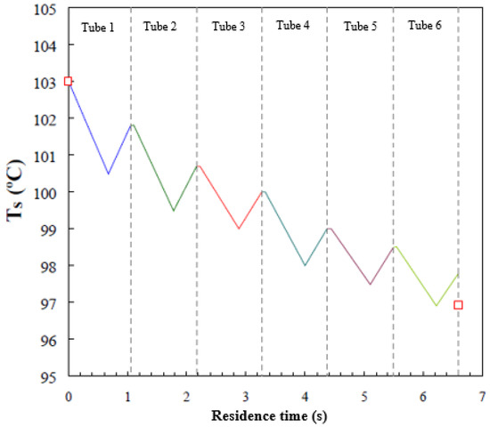
Figure 7.
Average temperature profile of the solution film versus residence time.
The solution temperature profile inside the falling-film absorber on horizontal tubes showed the same trends as those observed in similar investigations reported by Kirby and Perez-Blanco [8] and Jeong and Garimella [9], which both used water/LiBr as working fluid. It is worth noting that the results of these two investigations with water/LiBr were compared with experimental data reported by Nomura et al. [14].
As commented previously, the experimental horizontal tube falling-film absorber used by Alvarez and Bourouis [19] registered inlet and outlet temperatures, but not local temperatures inside the absorber. Therefore, it was not possible to validate local temperature profiles, and the comparison between simulation and experimental data was limited to outlet temperature and concentration. The actual inlet and outlet temperatures (red symbols) of the aqueous alkaline nitrate solution measured in the experimental setup are also shown in Figure 7. A deviation of 1 °C is observed in predicting the solution outlet temperature. This level of error is considered acceptable, since the assumptions considered in the mathematical model take into account a series of deviations from the real system. Mainly, the assumption of a perfect wetting of the tubes could be a very optimistic claim. The same order of error was found in the predictions of the solution temperature profiles reported by Kirby and Perez-Blanco [8] and Jeong and Garimella [9].
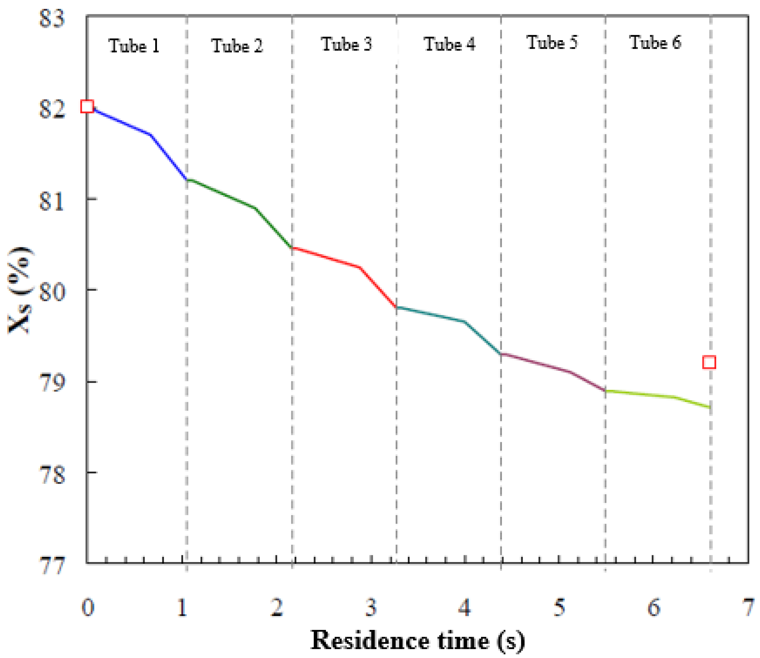
Figure 8 shows the local solution concentration profile along the tubes in the absorber. As can be observed, higher concentration differences between the inlet and the outlet of each tube occur in the first top tubes, where a larger amount of vapour is absorbed. Also, the variations in solution concentration in the falling-film flow regime and the droplet-formation flow regime are of the same level of magnitude, although in the droplet-formation flow regime, vapour is absorbed more rapidly (steeper gradient). On the other hand, vapour absorption during the droplet-fall flow regime is short due to the increase in solution temperature and the shorter residence time of this regime. Thus, mass transfer is basically attributed to the droplet-formation flow and falling-film flow regimes. Kirby and Perez-Blanco [8] presented the solution concentration profile as a function of residence time for their water/LiBr horizontal tube falling-film absorber. The concentration difference between the inlet and outlet of the absorber was less than 1.6%. Furthermore, a greater slope was observed in the droplet-formation flow regime than in the falling-film flow regime, which were 0.17 and 0.1, respectively. Figure 8 also includes experimental data of the solution concentration at the inlet and outlet of the absorber (red symbols). The deviation between the model prediction of the outlet solution concentration and the experimental data is 0.6%, by weight. The trends in Figure 8 are similar to those reported by Kirby and Perez-Blanco [8].
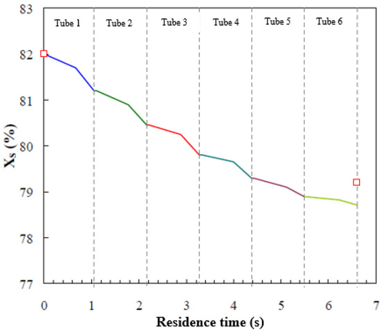
Figure 8.
Concentration profile of the solution film versus residence time.
Table 4 shows the absorbed vapour flow per unit of length of the tube at the base case operating conditions in Table 2. As can be observed, most of the vapour is absorbed in the falling-film flow and droplet-formation flow regimes. It is worthy of note that mass transfer rates achieved in these two flow regimes are of the same order of magnitude. The rate of absorption is higher for the top tubes than the bottom ones. This trend is due to the fact that, at the absorber entrance, i.e., the top tubes, there is a higher temperature gradient between the solution and the cooling water. However, in the lower tubes, there are smaller temperature and concentration differences between the solutions entering and leaving each tube, the result being a lower flow of absorbed vapour.
Table 4.
Vapour absorption rate in each flow regime and tube.
The total flow of absorbed vapour per unit of area, obtained from the simulation results, is 4.7 g·m−2·s−1, and represents a deviation of 22% from the experimental value. This deviation is attributed to the approximations integrated into the model. The mathematical model contemplates a perfect distribution of the solution along the tube, and complete surface wetting. However, experimental studies in the literature reported that the wetted surface area decreased gradually from the upper to the lower tubes (Nomura et al. [14]). The average wetting ratio could be 0.5 at certain operating conditions [9]. Jeong and Garimella [9] showed that a decrease of 20% in the wetting ratio (wet area/total area) caused an approximate 10% drop in the vapour absorption rate. Moreover, the transport coefficients were obtained from empirical correlations, which represent a simple estimation method but could also be a source of errors. In addition, these correlations are contingent to parameters such as droplet diameter, which were kept at constant reference values in the model.
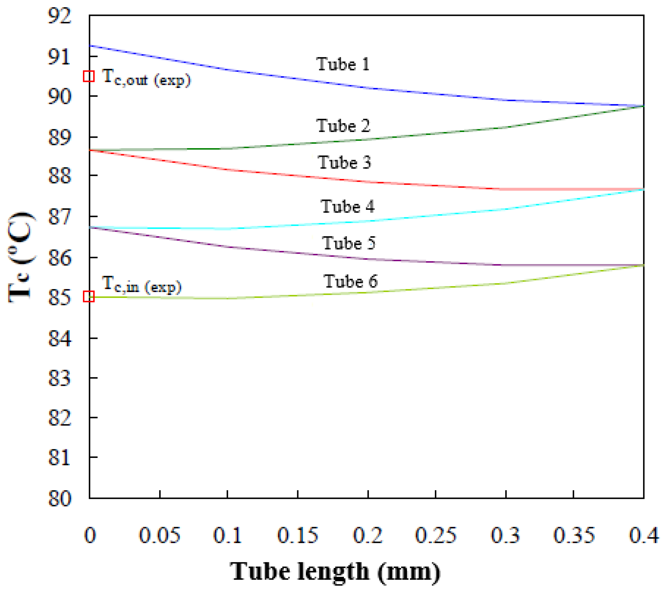
Figure 9 shows the longitudinal cooling water temperature profiles (lines) predicted by the mathematical model in the six tubes forming the absorber working at the operating conditions established in Table 1. The tubes are each 0.4 m long and they are connected in series, so that the outlet of one tube coincides with the inlet of the adjacent upper tube. The experimental water inlet and outlet temperatures [19], Tc,in and Tc,out respectively, are shown in Figure 9 (red square). The variation in cooling water temperature is shown, since it goes into tube 6, going up through the inside of tubes 5, 4, 3, 2, and 1, respectively. Finally, it leaves the absorber at a higher temperature (Tc,out) and consequently dissipates heat released during the absorption process.
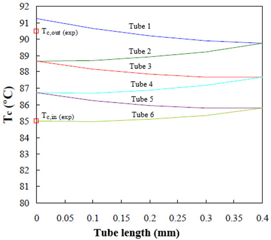
Figure 9.
Cooling water temperature profile along the tube bundle.
The cooling water temperatures at the absorber exit, predicted by the mathematical model, show an average deviation of 0.8 °C from the values noted experimentally with the absorber operating at the same conditions.
The results highlight the effect of the solution flow regimes on the absorption process using an aqueous (lithium, potassium, sodium) nitrate solution as a working pair. Absorption of vapour is negligible during the droplet-fall flow regime compared to the other flow regimes. Less than 0.01% of the overall absorbed vapour mass occurs in the droplet-fall flow regime, mainly because of the short residence time. On the other hand, the contribution of the droplet-formation flow regime in the vapour absorption process is slightly higher than that of the falling-film flow regime, except for the first tube. The effect of flow regimes on the absorber performance, at the specific operating conditions selected for the present study, is similar to that reported in the literature for conventional water/LiBr absorbers.
5.2. Effect of the Operating Conditions
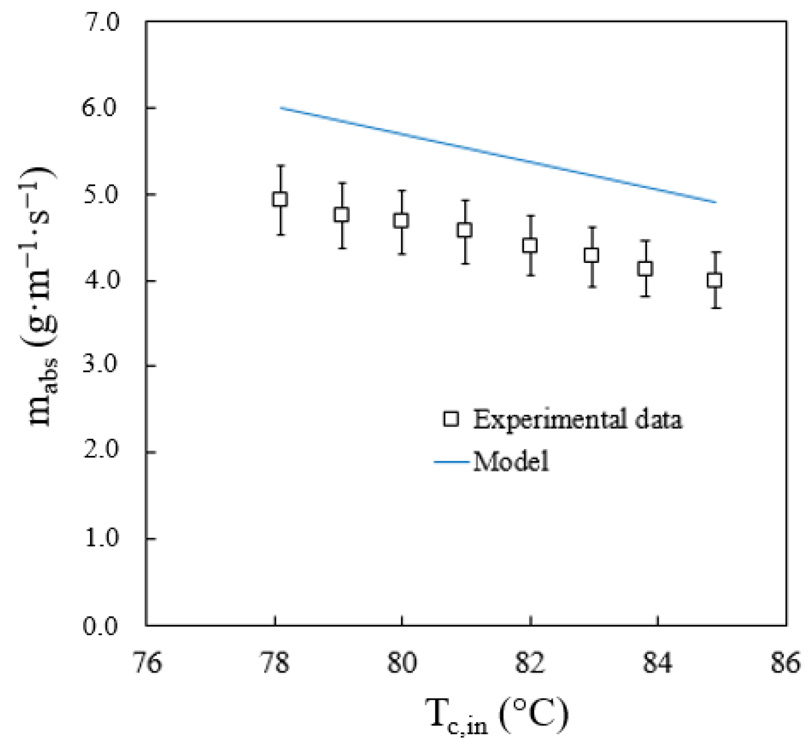
Evaluations were carried out to see how two variables could affect absorber performance. The variables were cooling water temperature, and solution flow rate at the inlet of the absorber. Figure 10 shows the influence of the cooling water temperature on the total flow of absorbed vapour. This figure includes the values of the absorbed vapour flow obtained experimentally and calculated by the model. Alvarez and Bourouis [19] reported an average uncertainty of the absorption rate of 8%. As expected, when the cooling water temperature increases, the vapour absorption rate decreases. The model accurately predicts the effect of the cooling water temperature since it shows that the absorption process improves when the cooling water temperature decreases. The average and maximum deviations in the prediction of the vapour absorption rate are 22% and 27.3%, respectively. The maximum deviation was obtained at the lowest solution flow rate studied. Therefore, it is assumed that the effect of tube wetting is a variable to be taken into account to improve the predictions of the model.

Figure 10.
Effect of cooling water temperature on the vapour absorption rate.
As mentioned before, the effect of the solution flow rate on absorber performance is very significant. This effect depends on the wetted area of the tubes, i.e., heat transfer area, and the flow regime prevailing between the tubes, i.e., droplets, streams, leaves. Figure 11 shows the total predicted vapour absorption rate versus the solution flow rate. As can be observed, the higher the solution flow rate, the lower the deviation between the value predicted by the mathematical model and the experimental data. This is because the wetted area on the tubes is smaller when the solution flow rate is low. This reduction in the heat transfer area was not taken into account by the mathematical model, thus the deviation between the experimental data and the calculated data is more pronounced.
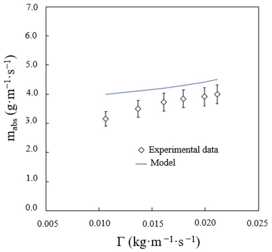
Figure 11.
Effect of solution flow rate on the vapour absorption rate.
The frequency of droplet formation is inversely proportional to the residence time of the solution, which, in this flow regime, increases with the solution flow rate. At low solution flow rates, in the falling-film flow regime, the solution temperature decreases at a higher proportion, but in the droplet-formation flow regime, the absorption process improves. Thus, the absorbed vapour is higher in one drop, but the frequency of droplet formation is lower. The net balance is, therefore, a lower absorbed vapour flow in the droplet-formation flow regime working at low solution flows.
6. Conclusions
The most significant conclusions, made from the present study, are summarized as follows:
The mathematical model developed integrates three flow regimes that characterize the absorption process in horizontal tube falling-film absorbers. These flow regimes are the droplet-formation flow regime, which occurs at the bottom of each tube making up the absorber, the droplet-fall flow regime, which takes place between the tubes, and the falling-film flow regime, which forms on the surface of the tubes. The mathematical model also includes the thermodynamic and transport properties of the aqueous alkaline nitrate solution. The model developed is able to assess the effect of these flow regimes on the operation and performance of an absorber.
The mathematical model predicts the temperature and concentration profiles of the alkaline nitrate solution, as well as the cooling water temperature profile, along the tubes of the absorber. Data concerning the temperature and concentration of the solution leaving the absorber and temperature at the cooling water outlet were predicted by the mathematical model. This data was then compared with experimental data obtained by Alvarez and Bourouis [19], who had used the same absorber design in a previous experimental work. The results of the two sets of data concurred closely. The average deviations for the solution temperature, solution concentration, and cooling water temperature were 1.1%, 0.6%, and 1%, respectively.
As regards the temperature and concentration profiles of the alkaline nitrate solution and the temperature profile of the cooling water circulating along the absorber tube bundle, there is no data available in the open literature that could allow for the validation of these local profiles. However, the trends of these profiles were compared with those reported in the literature (Nomura et al. [14], Kirby and Perez-Blanco [8], Jeong and Garimella [9]) using similar absorber configurations and working with the conventional fluid mixture water/LiBr. All sets of data showed similar trends to those obtained in the present work.
The total residence time of the solution in the absorber was 6.6 s. The residence time of the droplet-fall flow regime was negligible, and therefore, the main heat and mass transfer contributions were made by the falling-film and droplet-formation flow regimes. The model predicted that the solution temperature will increase by an average of 0.9 °C per tube and that the solution concentration will decrease by an average of 0.6% per tube. Additionally, the solution temperature experienced a drop of 1.8 °C in the falling-film flow regime and an increase of 1 °C, on average, in the droplet-formation flow regime. As regards the solution concentration, an average decrease of 0.21% and 0.34% per tube was observed in the falling-film flow and droplet-formation flow regimes, respectively.
The mathematical model developed also predicted the absorption rate at 4.7 g·m−2·s−1 for the absorber design and operating conditions used in the present work. This value is 22% higher than the value obtained by the authors in their previous experimental work. This deviation is attributed to the approximations made in the model, especially as regards surface wettability and the calculation of mass transfer coefficients for each flow regime.
Author Contributions
Conceptualisation, Formal analysis, Investigation, Methodology, M.E.Á. and M.B.; Software, Validation, Writing—original draft, M.E.Á.; Writing—review and editing, Supervision, Funding acquisition, M.B. All authors have read and agreed to the published version of the manuscript.
Funding
This study was part of an R&D project funded by the Spanish Ministry of Science and Innovation (ENE2007-65541/ALT).
Acknowledgments
M.E. Álvarez thanks D. Juárez Romero for sharing the mathematical model applied in his study (Juárez-Romero et al. 2009) during the stay at the “Centro de Investigación en Ingeniería y Ciencias Aplicadas de la Universidad Autónoma de Morelos” in Mexico.
Conflicts of Interest
The author declares no conflict of interest.
Nomenclature
| b1 | Bias vector of the ANN input layer |
| b2 | Bias vector of the ANN output layer |
| Cp | Specific heat kJ·kg−1·°C−1 |
| d | Tube diameter m |
| ddroplet | Droplet diameter m |
| D | Mass diffusivity coefficient of the solution m2·s−1 |
| DND | Average distance between the neighbouring droplets m |
| h | Heat transfer coefficient on the solution side W·m−2·°C−1 |
| hc | Heat transfer coefficient of the cooling water W·m−2·°C−1 |
| hs | Specific enthalpy of the solution kJ·kg−1 |
| hv | Specific enthalpy of saturated vapour kJ·kg−1 |
| I | Number of the input variables of ANN |
| k | Mass transfer coefficient m·s−1 |
| IW | Matrix weight of the ANN hidden layer |
| J | Number of the output variables of ANN |
| LW | Matrix weight of the ANN output layer |
| g | Gravity constant m·s−2 |
| Ga | Modified Galileo number |
| L | Tube length m |
| LiBr | Lithium bromide |
| m | Mass flow rate kg·s−1 |
| mc | Cooling water volumetric flow rate m3·s−1 |
| mdroplet | Droplet mass kg |
| N | Number of droplets per unit of length of the tube m−1 |
| NPTH | Non-plated through hole |
| Nu | Nusselt number |
| P | Pressure kPa |
| Pr | Prandtl number |
| Q | Heat duty kW |
| qabs | Absorption heat kJ·kg−1 |
| r | Radius m |
| rmse | Root mean square error |
| Re | Reynolds number |
| ST | Distance between the tubes m |
| t | Time s |
| T | Temperature °C |
| u | Velocity m·s−1 |
| U | Overall heat transfer coefficient W·m−2·°C−1 |
| V | Volume m3 |
| X | Solution mass concentration Weight % |
| z | Horizontal coordinates of the absorber m |
| Greek letters | |
| λ | Thermal conductivity W·m−1·°C−1 |
| δ | Film thickness m |
| µ | Dynamic viscosity kg·m−1·s−1 |
| Γ | Solution mass flow rate per unit of wetted tube length (m/2 L) kg·m−1·s−1 |
| ρ | Density kg·m−3 |
| σ | Surface tension N·m−1 |
| ξ | Length of the capillary tube m |
| Subscripts | |
| abs | Absorber |
| c | Cooling water |
| Cu | Copper |
| droplet | Droplet |
| form | Droplet-formation |
| fall | Droplet-fall |
| film | Falling-film |
| i | Internal |
| in | Inlet |
| o | External |
| out | Outlet |
| s | Solution |
| v | Vapour |
| eq | Equilibrium |
References
- Nagavarapu, A.; Garimella, S. Experimentally validated models for falling-film absorption around microchannel tube banks: Heat and mass transfer. Int. J. Heat Mass Transf. 2019, 139, 303–316. [Google Scholar] [CrossRef]
- Amaris, C.; Vallés, M.; Bourouis, M. Vapour absorption enhancement using passive techniques for absorption cooling/heating technologies: A review. Appl. Energy 2018, 231, 826–853. [Google Scholar] [CrossRef]
- Killion, J.; Garimella, S. A critical review of models of coupled heat and mass transfer in falling film absorption. Int. J. Refrig. 2001, 24, 755–797. [Google Scholar] [CrossRef]
- Grossman, G. Heat and mass transfer in film absorption. In Handbook of Heat and Mass Transfer; Gulf Publishing: Houston, TX, USA, 1986; pp. 211–257. [Google Scholar]
- Killion, J.; Garimella, S. Pendant droplet motion for absorption on horizontal tube banks. Int. J. Heat Mass Transf. 2004, 47, 4403–4414. [Google Scholar] [CrossRef]
- Bustamante, J.; Garimella, S. Experimental assessment of flow distributors for falling-films over horizontal tube banks. Int. J. Refrig. 2019, 101, 24–33. [Google Scholar] [CrossRef]
- Bohra, L.; Lee, S.; Garimella, S. Visual documentation of transfer processes in horizontal-tube falling-film ammonia-water absorbers. Int. J. Refrig. 2019, 103, 91–105. [Google Scholar] [CrossRef]
- Kirby, M.; Perez-Blanco, H. A design model for horizontal tube water/lithium bromide absorbers. ASME Heat Pump Refrig. Syst. Des. Anal. Appl. 1994, 32, 1–20. [Google Scholar]
- Jeong, S.; Garimella, S. Falling-film and droplet mode heat and mass transfer in a horizontal tube LiBr/water absorber. Int. J. Heat Masstransf. 2002, 45, 1445–1458. [Google Scholar] [CrossRef]
- Wassenaar, R.; Westra, J. Dynamic model of a film absorber with coupled heat and mass transfer. Int. J. Heat Mass Transf. 1992, 35, 87–99. [Google Scholar] [CrossRef]
- Patnaik, V.; Perez-Blanco, H. A counterflow heat-exchanger analysis for the design of falling-film absorbers. ASME Int. Absorpt. Heat Pump Conf. 1993, 31, 209–216. [Google Scholar]
- Patnaik, V.; Perez-Blanco, H.; Ryan, W. A simple analytical model for the design of vertical tube absorbers. Asrae Trans. 1993, 99, 69–80. [Google Scholar]
- Seewald, J.; Perez-Blanco, H. A simple model for calculating the performance of Lithium Bromide/Water Coil Absorber. Ashrae Trans. 1994, 100, 318–328. [Google Scholar]
- Nomura, T.; Nishimura, N.; Wei, S.; Yamaguchi, S.; Kawakami, R. Heat and mass transfer mechanism in the absorber of water/LiBr conventional absorption refrigerator: Experimental Examination by Visualized Model. In International Absorption Heat Pump Conference; The Advanced Energy Systems Division; ASME: New Orleans, LA, USA, 1993; pp. 203–208. [Google Scholar]
- Juárez-Romero, D.; Shah, N.; Pliego-Solórzano, P.; Hernández, J.; Siqueiros, J.; Huicochea, A. Heat and mass transfer in a horizontal pipe absorber for a heat transformer. Desalin. Water Treat. 2009, 10, 238–244. [Google Scholar] [CrossRef]
- Holland, F.A.; Siqueiros, J.; Santoyo, S.; Heard, C.L.; Santoyo, E.R. Water Purification Using Heat Pumps; E & FN Spon/Routledge: London, UK; New York, NY, USA, 1999. [Google Scholar]
- Davidson, W.; Erickson, D. 260 °C Aqueous absorption working pair under development. Newsl. IEA Heat Pump Cent. 1986, 4, 29–31. [Google Scholar]
- Álvarez, M.E.; Esteve, X.; Bourouis, M. Performace analysis of a triple-effect absorption cooling cycle using aqueous (lithium, potassium, sodium) nitrate solution a working pair. Appl. Therm. Eng. 2015, 79, 27–36. [Google Scholar] [CrossRef]
- Álvarez, M.E.; Bourouis, M. Experimental characterization of heat and mass transfer in a horizontal tube falling film absorber using aqueous (lithium, potassium, sodium) nitrate solution as a working pair. Energy 2018, 148, 876–887. [Google Scholar] [CrossRef]
- Álvarez, M.E. Theoretical and Experimental Study of the Aqueous Solution of Lithium, Sodium and Potassium Nitrates as a Working Fluid in Absorption Chillers Driven by High Temperature Heat Sources. Ph.D. Thesis, Rovira i Virgili University, Tarragona, Spain, 2013. (In Spanish). [Google Scholar]
- Wassenaar, R.; Machielsen, C. Simulation of the film flow on a horizontal tube Fed by Falling Droplets. In Proceedings of the 18th International Symposium on Heat and Mass Transfer in Cryogenics and Refrigeration, Dubrovnik, Yugoslavia, 1–5 September 1986; Begell House Inc.: Dubrovnik, Yugoslavia, 1986; pp. 277–284. [Google Scholar]
- Taghvi-Tafreshi, K.; Dhir, V. Taylor inestability in boiling, melting and condensation or evaporation. Int. J. Heat Mass Transf. 1980, 23, 1433–1445. [Google Scholar] [CrossRef]
- Hu, X.; Jacobi, A. The intertube falling film: Part 1 flow characteristics, mode transitions, and hysteresis. J. Heat Transf. 1996, 118, 616–625. [Google Scholar] [CrossRef]
- Hu, X.; Jacobi, A. Departure-site spacing for liquid droplets and jet falling between horizontal circular tubes. Exp. Therm. Fluid Sci. 1998, 16, 322–331. [Google Scholar] [CrossRef]
- Clift, R.; Grace, J.; Weber, M. Bubbles, Drops and Particles; Academic Press: Cambridge, MA, USA, 1978. [Google Scholar]
- Álvarez, M.E.; Hernandez, J.A.; Bourouis, B. Modelling the performance parameters of a horizontal falling film absorber with aqueous (lithium, potassium, sodium) nitrate solution using artificial neural networks. Energy 2016, 102, 313–323. [Google Scholar] [CrossRef]
- Andberg, J.; Vliet, G. A simplified model for absorption of vapors into liquid films flowing over cooled horizontal tubes. Ashrae Trans. 1987, 93, 2454–2466. [Google Scholar]
- Skelland, A.; Minhas, S. Dispersed phase mass transfer during drop formation and coalescence in liquid-liquid extraction. Am. Inst. Chem. Eng. J. 1971, 17, 1316–1324. [Google Scholar] [CrossRef]
- Heertjes, P.; Holve, W.; Talsma, H. Mass transfer between isobutanol and water in a spray-column. Chem. Eng. Sci. 1954, 3, 122–142. [Google Scholar] [CrossRef]
- Whitman, W. Preliminary experimental confirmation of the two-film theory of gas absorption. Chem. Metall. Eng. 1923, 29, 146–148. [Google Scholar]
- Bird, R.; Stewart, W.; Lightfoot, E. Transport Phenomena, 2nd ed.; John Wiley & Sons Inc.: Hobokem, NJ, USA, 2001. [Google Scholar]


Publisher’s Note: MDPI stays neutral with regard to jurisdictional claims in published maps and institutional affiliations. |
© 2021 by the authors. Licensee MDPI, Basel, Switzerland. This article is an open access article distributed under the terms and conditions of the Creative Commons Attribution (CC BY) license (http://creativecommons.org/licenses/by/4.0/).