Abstract
Air-core coil current transformer is a key piece of equipment in the digital substation development. However, it is more vulnerable to various faults when compared with the traditional electromagnetic current transformer. Aiming at understanding the effect of various parameters on the performance of the air-core coil current transformer, this paper investigates the influence of these factors using the maximum information coefficient. The interference mechanism of influencing factors on the transformer error is also analyzed. Finally, the Stacking model fusion algorithm is used to predict transformer errors. The developed base model consists of deep learning, integrated learning and traditional learning algorithms. Compared with gated recurrent units and extreme gradient boosting algorithms, the prediction model based on stacking model fusion algorithm proposed in this paper features higher accuracy and reliability which helps improve the performance and safety of future digital substations.
1. Introduction
Electronic current transformer (ECT) plays a key role in the digital substations as its performance is directly related to the secondary side of the power system security and the accuracy of control and protection systems. Compared with traditional electromagnetic transformers, ECT has the advantages of high insulation, good anti-electromagnetic interference performance, wide dynamic range and high measurement accuracy [1,2,3]. However, ECT has a significant high failure rate, which affects the reliability of the entire power system [4].
Much research effort has been conducted to improve the performance and reliability of ECT. The published conventional approaches to evaluate the ECT state can be divided into periodic off-line verification and long-term on-line verification methods. The periodic off-line verification method is to evaluate the ratio difference, angle difference and other parameters through comparison with a standard transformer within a certain period in the off-line state. The disadvantage of this method is its offline nature which causes power outage [5]. The long-term on-line verification method is to put the standard transformer into the power grid for comparison within a certain period. This method can effectively reduce the power grid outage time by a proper and reliable design of the standard transformer live access method [6]. Periodic off-line verification and long-term on-line verification methods call for external equipment intervention to analyze ECT status. Therefore, some researchers conduct on-line evaluation through various faults and corresponding electrical parameters of the ECT. In [7], wavelet theory is proposed to analyze the relationship between ECT fault mode and electrical quantity of the primary system. In [8], fault mode characteristic parameters of optical voltage transformer are extracted and used by an artificial neural network model to predict the fault type.
The above methods can diagnose the ECT faults upon their occurrence without much ability to detect incipient faults to avoid any potential consequences. This paper presents a detailed error analysis of the ECT based on environmental and operating conditions. This analysis is aimed at detecting any minor variation in the ECT measurement accuracy and providing timely asset management decision to maintain the reliability of the ECT and hence achieving reliable and safe operation of the power system.
Not much attention was given in the literature to study the influence of temperature, magnetic field, humidity, vibration and other environmental parameters on the error of the ECT. However, the recent and rapid development of artificial intelligence and machine learning has provided a new effective way for such studies [9,10,11,12,13]. Traditional error prediction approaches mainly includes regression analysis, time series and grey model methods. On the other hand, intelligent prediction includes artificial neural network, support vector machine and wavelet analysis methods. Several research studies have optimized the above algorithms mainly on decomposing and predicting the input variables and optimizing the prediction parameters to achieve better results [14,15].
Aiming at improving the reliability and stability of ECT, this paper proposes a stack model fusion [16] to predict the ratio and angle errors without the need for standard verification as per the current industry practice. Three types of six frontier algorithms are selected as the base models to predict the errors from different angles. The basic learning models include deep learning algorithm long, short term memory (LSTM) and gate recurrent unit (GRU), extreme gradient boosting (XGBoost) and light gradient boosting machine (LightGBM) along with two traditional machine learning algorithms; support vector machine (SVM) and k-nearest neighbor (KNN). In order to get the full advantages of different algorithms, prediction results of the basic model are used as input to the meta model.
2. Principle and Interference Mechanism Analysis of Air-Core Coil Current Transformer
2.1. Principle Analysis
Air-core coil current transformer is mainly composed of Rogowski coil and digital converter, as shown in Figure 1. The principle structure and output signal of the air-core coil current transformer are different from traditional electromagnetic current transformers, whose performance is affected by environmental temperature and external magnetic field. Rogowski coil, which is a kind of air-core solenoid tightly wound on a non-magnetic frame acts as a sensing head [17,18,19]. The flux linkage Φ of the entire coil is calculated from:
where H is the magnetic field strength at the dl section of the coil, n is the number of turns per unit length of the coil, s is the cross-sectional area of the coil, µ0 is the permeability of free space.
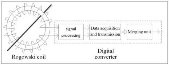
Figure 1.
Basic structure of an air-core coil current transformer.
If n and s are uniform in all parts of the coil, then (2) is satisfied:
If the measured current i is an alternating current, the induced potential e(t) of the coil is:
From (3), it can be seen that the induced potential of Rogowski coil is directly proportional to the differentiation of the measured current. Then the measured current can be obtained by integrating e(t) through an electronic circuit.
Figure 2 shows the circuit diagram for measuring the error of a current transformer of a hollow coil. In this test, a standard current transformer (CT) and the hollow coil current transformer are connected in series. The secondary output of the standard current transformer is converted into a voltage signal through a resistance. The voltage signal is fed into the input of an analog to digital (A/D) converter whose output port is connected to a calibrator. The output of the air-core coil current transformer is connected to a merging unit that converts the input signal into a digital signal and transmits it to the calibrator through optical fiber. The A/D and the pulse of the hollow coil current transformer are sampled synchronously using a synchronized clock. The calibrator compares the two input signals and calculates the ratio difference and angle difference [20].
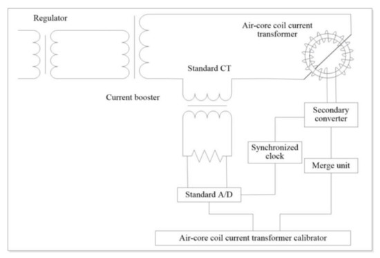
Figure 2.
Schematic for error test of an air-core coil current transformer.
2.2. Interference Mechanism Analysis
In order to study the correlation between the air-core coil current transformer error and the environmental and operating conditions such as temperature, magnetic field, humidity and vibration, the maximum information coefficient (MIC) based on mutual information theory is adopted. This approach was firstly proposed in 2011, to detect various types of association relations based on mutual information [21]. The MIC is suitable for exploring the potential relationship between variable pairs in large data sets as it is robust and is not affected by outliers. The calculation of the MIC value for two variables X and Y, is performed based on the below three steps:
(1) Under the given grid resolution, the two-dimensional scatter map composed of X and Y is divided according to different partition schemes, and the maximum mutual information value is obtained.
(2) The maximum mutual information value is divided by log(min (x, y)) as shown in (4) and is normalized to be in the range [0, 1]. MIC value close to 1 reflects a strong correlation between X and Y variables.
(3) The grid resolution is to be changed and steps (1) and (2) are repeated and the maximum mutual information of different scales is selected as the MIC value.
In general, , B is a function of the sample size n. is the largest mutual information value in the grid area D.
In this paper, the error and environmental parameter data of an air-core coil current transformer in a real digital substation are collected in the year 2016. Four groups of 10 min average data are used for the error prediction. There are two groups of ratio difference and two groups of angle difference in which each group contains 3000 samples. The first-2000 samples are used for training, while the remaining 1000 samples are used as test targets, as shown in Figure 3. The descriptive statistics of errors are shown in Table 1. Figure 4 and Figure 5 show the heat maps of the average correlation matrix between the training features and targets. Figure 4 shows the maximum information coefficient of the ratio difference while Figure 5 shows the maximum information coefficient of the angle difference. The color of each square cell represents the value of the correlation coefficient between each feature, and the red (blue) area represents the strong (weak) correlation.
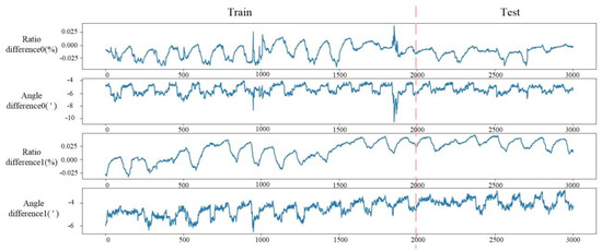
Figure 3.
Four sets of 10 min averaged error time series.

Table 1.
Descriptive statistics of the error data.
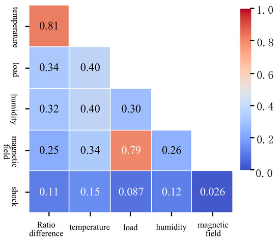
Figure 4.
Heat map of matrix with maximum mutual information coefficient of ratio difference.
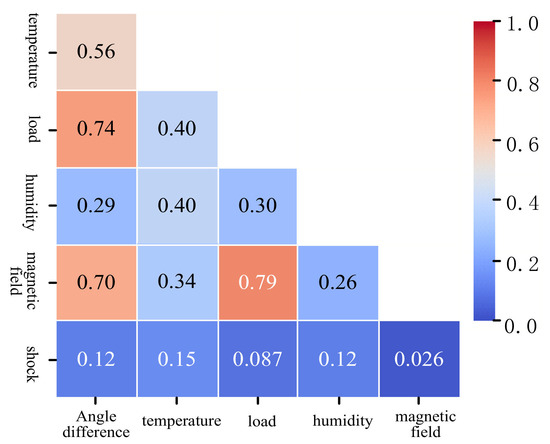
Figure 5.
Heat map of matrix with maximum mutual information coefficient of angle difference.
According to Figure 4 and Figure 5, the main factors influencing the performance of the air-core coil current transformer are the temperature, load, humidity and magnetic field. Temperature is the dominant factor affecting the ratio difference. On the other hand, the load and magnetic field are the dominant factors affecting the angle difference. There is a strong correlation between electrical parameter, load and the magnetic field, which may be due to the influence of air-core coil current transformer secondary side current on the external magnetic field measurement.
The performance of the air-core coil current transformer is mainly affected by ambient temperature and external magnetic field. This is mainly because the output signal of the coil is related to the coil cross-section area s and the turns’ number n, and the temperature variation directly affects n and s. The change of the temperature also affects the integration and filtering of the digital converter, thus affecting the output of the transformer.
If the first order filter circuit shown in Figure 6 has a sinusoidal input voltage , the output signal amplitude is:
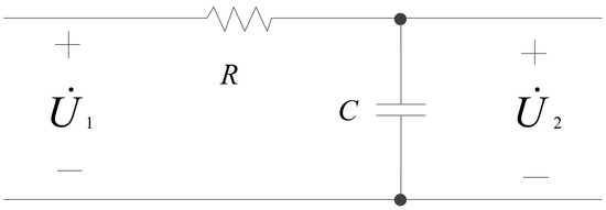
Figure 6.
First order filter circuit.
The amplitude of the output signal of the integrator shown in Figure 7 is:
where and are coefficients related to the values of the resistance and capacitance used in the circuit. While is less affected by the temperature, is greatly affected so the main digital converter affected by the temperature is the integrator circuit.
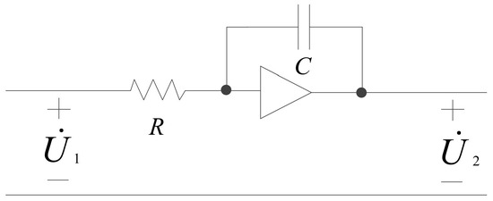
Figure 7.
An integrating circuit.
Rogowski coil does not contain iron core, and its output signal is easily affected by external variable magnetic field , which can be decomposed into two components; vertical to the coil and parallel to the coil components. The vertical component and parallel component affect the air-core coil current transformer in different aspects. If n and s are uniform, the magnetic field interference of the parallel component has no effect on the transformer while the vertical component passes through the large circle surrounded by the air-core coil and the output end of the coil will generate induction electromotive force which affects the performance of the transformer. In addition to temperature, humidity has some influence on the performance of the Rogowski coil and the digital converter.
When a short-circuit fault occurs in the power system, the air-core coil current transformer exhibits a short-circuit current of high amplitude that causes a significant electrodynamic effect. During the operation of the circuit breaker, the air-core coil current transformer will also exhibit a strong vibration due to the transmission of the connecting wire, especially for spring-type circuit breaker. Vibration may change the relative position between the air-core coil and the primary current carrying conductor and resulting in eccentricity measurement error. The data in this paper are obtained during normal operation, so the influence of vibration on the error can be neglected.
3. Used Algorithms
3.1. Stacking Algorithm
Stacking model fusion algorithm was firstly proposed by Wolpert in 1992. By combining several different prediction algorithms, it can be regarded as a special combination strategy model [22,23]. Stacking algorithm is mainly divided into two layers. The first layer is the base learner, and the second layer is the meta learner. Firstly, the original data set is divided into several sub datasets, which are fed to the base learner training that results in feature training meta learner, as shown in Figure 8. Stacking model fusion algorithm helps improve the overall prediction accuracy.
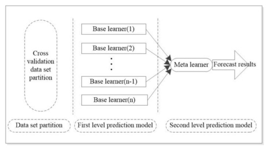
Figure 8.
Learning method based on stacking algorithm.
The ratio difference and angle difference of an ECT are affected by many factors, such as equipment technology and external environment. ECT error and influencing factors present multi-dimensional nonlinear relationship. Single machine learning algorithm can’t map an effective relationship between transformer error and influencing factors in multi-dimensional, and it is easily affected by data set and model parameters. As such stacking model fusion algorithm is adopted to map this correlation.
The first layer comprises the advantages of different prediction algorithms, so that differential models can learn from each other. In this paper, three kinds of six types of frontier algorithms with small correlation degree are used to make up the stacking integrated model. The base learners include: XGBoost and LightGBM, LSTM and GRU, SVM and KNN. SVM is selected as the second layer learner, which performs well in solving small sample, nonlinear and high dimensional regression problems.
In order to obtain high prediction accuracy, the model with large difference is selected as the base learner in the first layer of the stacking model. This is because for different algorithms, it is essential to observe data in different data space and data structure angles to establish the corresponding model according to the observation status of the algorithm. The algorithm with large difference degree can reflect the advantages of different algorithms to a great extent, so that each differentiation model can learn from each other. In addition, cross validation method is used to adjust parameters in grid search algorithm to improve the prediction ability of each base and meta models.
It is to be noted that using the training results of base learners directly as the feature set of meta learners may lead to serious over fitting, and the structure along with the super parameters of each model will be inconsistent and difficult to adjust. K-fold cross validation and grid search methods are used to solve the “over fitting” and parameter optimization problems. The overall algorithm is shown in Figure 9.
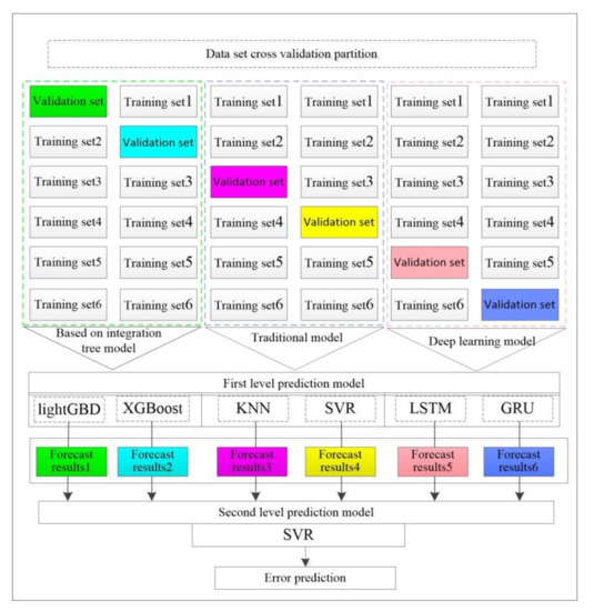
Figure 9.
Error forecasting research based on multi-model under stacking framework.
The training process of air-core coil current transformer error prediction method based on stacking model fusion algorithm is described below:
(1) Firstly, k-fold cross validation algorithm is used to divide the training data set into equal k-subsets. These subsets do not overlap with each other and are recorded as . For each base learner, one subset is selected as the verification set, and the other k-1 subset is selected as the test training set.
(2) Training and prediction of base learners: using , train the base learner 1 and pair the trained base learner 1 with the verification set and the test set. Then apply , to train the base learner 2 and pair the trained base learner 2 with the verification set and the test set. In the same way, each base learner cycles k times, then combine the k-time prediction results from the training of the validation set and take the average value of the prediction results of k-test sets. The length of the merged data set is the same as that of the original data set.
(3) Training and testing of meta learners: a new training set is constructed from the k test results of the verification set output from the first level model, which is used to train the second level prediction model. A new test set is constructed by averaging the k-times prediction results of the test set output from the first layer model, and the final prediction results are obtained.
3.2. XGBoost Algorithm
XGBoost is a cutting-edge artificial intelligence technology, which occupies a dominant position in machine learning and Kaggle structured or data competition. It is a must kill weapon in big data competitions [24]. XGBoost is an integrated learning algorithm optimized from gradient lifting tree model. The predictor is composed of many small predictors. The tree model is added by feature splitting. Each added tree is equivalent to adding a new function to the model to fit the last predicted residual. The loss function consists of two parts:
The training errors of real value and the predicted value are
A penalty function to prevent the training model from being over fitted is:
where and denote the penalty coefficient of the model; T is the number of model trees; is the weight value of the jth leaf node.
3.3. GRU Algorithm
GRU, as a variant of LSTM, adopts the structure of gated cyclic neural network, which has less training parameters than LSTM, while maintaining the prediction effect of LSTM [25,26]. GRU internal unit is similar to LSTM internal unit, but the input gate and the forgetting gate will be combined into an update gate in GRU algorithm. Therefore, GRU algorithm has only two gate structures, including an update gate and a reset gate. The function of the update gate is to control the state information of the previous time and the degree of retention in the current state. The larger the value of the update gate, the more state information will be retained. The function of the reset gate is to determine whether the current state is combined with the previous information. When the value of reset gate is larger, more information will be ignored.
3.4. SVM Algorithm
The basic principle of support vector machine is to map input space to high-dimensional space through a nonlinear mapping . The high-dimensional space is linearly separable by the function , where w is the weight vector and b is the offset [27].
By minimizing the structural risk and constructing a loss function, according to statistical theory, support vector machine structures the regression function by minimizing an objective function as below:
where and are non-negative relaxation variables; is the penalty factor, which is a compromise between the empirical risk and the model complexity; and is the insensitive loss function parameter.
3.5. Forecast Evaluation
In order to evaluate the prediction results, four performance indicators are used in this study. Mean absolute error (), root mean square error (), which is the percentage improvement of the mean absolute error and that represents the percentage improvement of the root mean square error, as defined below:
where and represent the true and predicted values at the i moment, respectively; n is the number of predicted samples.
4. Air-Core Coil Current Transformer Case Study
4.1. Data Processing
It is necessary to quantify the influence factors and errors of the air-core coil current transformer. Besides, in order to simplify the prediction model and speed up the prediction, temperature, load, humidity and magnetic field which have strong correlation with the error are selected as the model inputs. Data normalization is adopted to reduce the effective data between [0, 1]. The maximum and minimum normalization formula is:
4.2. Prediction Analysis
The angle difference and ratio difference of air-core coil current transformer fluctuate not only due to the fluctuation of the primary current, but also due to the variation of the environmental temperature and surrounding magnetic field. As the error fluctuates greatly and randomness is large, traditional single machine learning algorithm is difficult to provide high prediction accuracy. As such, stacking model fusion algorithm can be used to resolve this problem. So as to check the prediction performance of the proposed Stacking fusion model, the prediction effect of XGBoost and GRU of the base model is compared with that of the Stacking integrated model.
Figure 10, Figure 11, Figure 12 and Figure 13 show the error prediction of air-core coil current transformer, and Table 2 and Table 3 present the prediction and evaluation of the experimental test. According to the chart analysis, stacking model fusion algorithm has satisfactory prediction performance. Compared with XGBoost and GRU algorithms, stacking fusion algorithm has the best effect in two groups of error prediction. For the error prediction of four groups of current transformers with hollow coil, the MAE and RMSE predicted by the stacking model are the smallest, and the predicted values are in line with the actual values. Stacking prediction model is has the ability to diagnose whether the transformer error is due to faulty conditions or not, so as to provide proper and timely maintenance scheme.
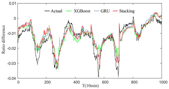
Figure 10.
Ratio difference 0.
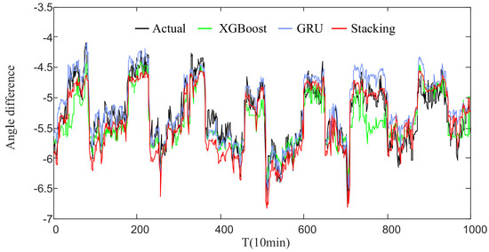
Figure 11.
Ratio difference 1.
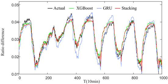
Figure 12.
Angle difference 0.
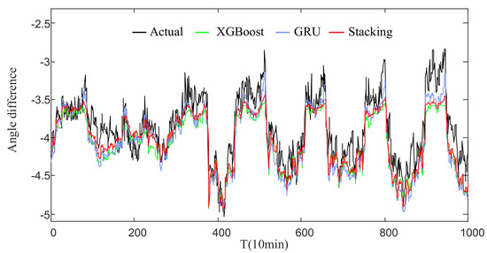
Figure 13.
Angle difference 1.
Table 2.
Analysis results of ratio difference prediction.
Table 3.
Analysis results of angle difference prediction.
The error of XGBoost model and GRU model is slightly larger at the peak, while the Stacking model is closer to the actual value. For angle difference prediction, the curve predicted by the Stacking model is relatively stable, which reveals the full adoption to the advantages of each individual algorithm. Stacking model also discards the link with poor prediction effect in each individual algorithm which results in a better prediction accuracy. The first mock exam space of the current model of the air-core coil current transformer is often very large, and there are probably several assumptions that can achieve the same performance on the training set. Stacking model fusion method can effectively reduce the risk of a single model generalization performance. From the point of the model optimization, the first mock exam often involves the risk of falling into a local minimum point, and the generalization performance of some local minimum points is probably more. The risk of falling into local minima can be effectively reduced by combining multiple base models after running.
In order to quantify the prediction improvement of the proposed model, and are calculated for the XGBoost and GRU models with respect to the Stacking model. The error predicted by the proposed stacking model is closer to the actual error. If the model is used to compensate the measurement error, a good result will be obtained. As shown in the Table 4:
Table 4.
Percentage improvement of stacking model.
(1) Stacking ensemble learning algorithm is better than XGBoost algorithm with regards to error compensation. In the four experimental tests, the index of error decreases by 2.27%, 11.05%, 7.63% and 18.51%; respectively, and the index of error is decreases by 7.80%, 14.53%, 6.95% and 16.06%; respectively.
(2) Stacking ensemble learning algorithm is better than GRU algorithm in error compensation. In the four experimental tests, the index of error decreases by 3.20%, 6.71%, 34.87% and 11.51%; respectively, and the index of error decreases by 3.20%, 6.77%, 35.10% and 8.60%; respectively.
5. Conclusions
The error of air-core coil current transformer exhibits large fluctuation and randomness and has multi-dimensional nonlinear correlation with the environmental parameters. In this paper, mutual information coefficient is used to get the main factors affecting the error of air-core coil current transformer, and then the mechanism of the effect of environmental parameters on the error of air-core coil current transformer is analyzed theoretically. The base model of Stacking fusion algorithm is used to integrate the prediction results of multi-dimensional prediction models in order to conquer the shortcomings of single model, that include low generalization and applicability. The average MAE and RMSE for the ratio and angle differences of the Stacking model are found to be 0.0025, 0.0031, 0.1909 and 0.2358; respectively. Reported results provide a broader vision for transformer error prediction that facilitate accurate evaluation of transformer reliability, stability and security of power systems.
Author Contributions
Conceptualization, Z.L. (Zhenhua Li); methodology, Z.L. (Zhenhua Li) and X.C.; software, X.C., L.W. and T.W.; validation, Y.Z., Z.L. (Zhenxing Li) and Y.X.; formal analysis, A.-S.A.; investigation, L.W. and T.W.; resources, Y.T. and H.L.; writing—original draft preparation, A.-S.A. and X.C.; writing—review and editing, A.-S.A.; visualization, X.C.; supervision, Z.L. (Zhenhua Li). All authors have read and agreed to the published version of the manuscript.
Funding
This work was supported in part by the Key Project of Science and Technology Research Plan of Education Department of Hubei under Grant D20201203, in part by the Natural Science Foundation of Hubei Province under Grand 2018cfb189, in part by Research Fund for Excellent Dissertation of China Three Gorges University under Grant 2021SSPY066.
Institutional Review Board Statement
Not applicable.
Informed Consent Statement
Not applicable.
Conflicts of Interest
The authors declare no conflict of interest.
References
- Jiang, J.; Zhao, M.; Zhang, C.; Chen, M.; Liu, H.; Albarracín, R. Partial Discharge Analysis in High-Frequency Transformer Based on High-Frequency Current Transducer. Energies 2018, 11, 1997. [Google Scholar] [CrossRef]
- Tamus, Z.Á. High frequency behavior of Rogowski-coil passive L/r integrator current transducer. In IEEE Postgraduate Conference on Electrical Power Systems; IEEE: New York, NY, USA, 2002; Volume 8, pp. 115–118. [Google Scholar]
- Li, Z.; Yu, C.; Abu-Siada, A.; Li, H.; Li, Z.; Zhang, T.; Xu, Y. An online correction system for electronic voltage transformers. Int. J. Electr. Power Energy Syst. 2021, 126, 106611. [Google Scholar] [CrossRef]
- Hu, C. Research on the Key Problems with Reliability and Long-Term Ability of Air-Core Coil Current Transformers. Ph.D. Thesis, Huazhong University of Science and Technology, Wuhan, China, 2018. [Google Scholar]
- Guo, W.; Zhang, H.; Yu, Z. A verfication system for electrical transformers with analog output. Power Syst. Prot. Control 2010, 38, 49–51. [Google Scholar]
- Li, Z.; Li, H.; Zhang, Z. An accurate online verfication system based on combined clamp-shape coil for high voltage electronic current transformers. Rev. Sci. Instrum. 2013, 84, 075113. [Google Scholar] [CrossRef] [PubMed]
- Xiong, X.; He, N.; Yu, J.; Chen, X.T.; Zi, M.R.; Hu, Z.R. Diagnosis of Abrupt-Changing Fault of Electronic Instrument Transformer in Digital Substation Based on Wavelet Transform. Power Syst. Technol. 2010, 34, 181–185. [Google Scholar]
- Jiang, Y.; Wang, J.; Li, J.; Yu, W.; Chen, B. Application of Artificial Neural Network to Fault Diagnosis for Optical Voltage Transformer. Proc. CSU EPSA 2018, 30, 134–139. [Google Scholar]
- Volovich, G.I. The Influence of Internal Noise on Electronic Current Transformer Error. Meas. Tech. 2016, 59, 164–169. [Google Scholar] [CrossRef]
- Li, Z.; Xiang, X.; Hu, T.; Abu-Siada, A.; Li, Z.; Xu, Y. An improved digital integral algorithm to enhance the measurement accuracy of Rogowski coil-based electronic transformers. Int. J. Electr. Power Energy Syst. 2020, 118, 105806. [Google Scholar] [CrossRef]
- Liu, G.; Zhao, P.; Qin, Y.; Zhao, M.; Yang, Z.; Chen, H. Electromagnetic Immunity Performance of Intelligent Electronic Equipment in Smart Substation’s Electromagnetic Environment. Energies 2020, 13, 1130. [Google Scholar] [CrossRef]
- Li, Z.; Jiang, W.; Abu-Siada, A.; Li, Z.; Xu, Y.; Liu, S. Research on a Composite Voltage and Current Measurement Device for HVDC Networks. IEEE Trans. Ind. Electron. 2020, 1. [Google Scholar] [CrossRef]
- Ding, Y.; Wu, Q.; Yang, G. Adaptive ultra-short-term wind power prediction based on risk assessment. CSEE J. Power Energy Syst. 2016, 2, 59–64. [Google Scholar] [CrossRef]
- Liu, H.; Mi, X.; Li, Y. Smart deep learning based wind speed prediction model using wavelet packet decomposition, convolutional neural network and convolutional long short term memory network. Energy Convers. Manag. 2018, 166, 120–131. [Google Scholar] [CrossRef]
- Wang, Z.; Hong, T.; Piette, M.A. Building thermal load prediction through shallow machine learning and deep learning. Appl. Energy 2013, 84, 114683. [Google Scholar] [CrossRef]
- Shi, J.; Zhang, J. Load Forecasting Based on Multi-model by Stacking model fusion. CSEE 2019, 39, 4032–4042. [Google Scholar]
- Luo, S.; Tian, C.; Zhao, X. Performance analysis of air-core current transformer. CSEE 2004. [Google Scholar] [CrossRef]
- Orosz, T.; Tamus, Z.Á.; Vajda, I. Modeling the high frequency behavior of the Rogowski-coil passive L/r integrator current transducer with analytical and finite element method. In Proceedings of the 2014 49th International Universities Power Engineering Conference (UPEC), Cluj-Napoca, Romania, 2–5 September 2014. [Google Scholar]
- Samimi, M.H.; Mahari, A.; Farahnakian, M.A.; Mohseni, H. The Rogowski Coil Principles and Applications: A Review. IEEE Sens. J. 2015, 15, 651–658. [Google Scholar] [CrossRef]
- Xu, Z.; Hu, H.; Xiong, Q.; Nie, Q.; Peng, H. Error Analysis and Online Experimental Research of Electronic Current Transformer. Sci. Technol. Eng. 2016, 16-24, 198–204. [Google Scholar]
- Ge, R.; Zhou, M.; Luo, Y.; Meng, Q.; Mai, G.; Ma, D.; Wang, G.; Zhou, F. McTwo: A two-step feature selection algorithm based on maximal information coefficient. BMC Bioinform. 2016, 17, 142. [Google Scholar] [CrossRef]
- Jiang, M.; Liu, J.; Zhang, L.; Liu, C. An improved Stacking framework for stock index prediction by leveraging tree-based ensemble models and deep learning algorithms. Phys. A Statal Mech. Appl. 2020, 541, 122272. [Google Scholar] [CrossRef]
- Luo, Z.; Mo, H.; Wang, R.; Hu, S.; Fang, S. Loss of voltage fault identification algorithm based on Stacking model fusion. China Energy Environ. 2019, 41, 41–45. [Google Scholar]
- Ma, X.; Sha, J.; Wang, D.; Yu, Y.; Yang, Q.; Niu, X. Study on a prediction of P2P network loan default based on the machine learning LightGBM and XGboost algorithms according to different high dimensional data cleaning. Electron. Commer. Res. Appl. 2018, 31, 24–39. [Google Scholar] [CrossRef]
- Zheng, H.; Yuan, J.; Chen, L. Short-Term Load Forecasting Using EMD-LSTM Neural Networks with a XGBoost Algorithm for Feature Importance Evaluation. Energies 2017, 10, 1168. [Google Scholar] [CrossRef]
- Liu, B.; Fu, C.; Bielefield, A.; Liu, Y.Q. Forecasting of Chinese Primary Energy Consumption in 2021 with GRU Artificial Neural Network. Energies 2017, 10, 1453. [Google Scholar] [CrossRef]
- Yao, G.; Pang, S.X.; Ying, T.; Benbouzid, M.; Ait-Ahmed, M.; Benkhoris, M.F. VPSO-SVM-Based Open-Circuit Faults Diagnosis of Five-Phase Marine Current Generator Sets. Energies 2020, 13, 6004. [Google Scholar] [CrossRef]


Publisher’s Note: MDPI stays neutral with regard to jurisdictional claims in published maps and institutional affiliations. |
© 2021 by the authors. Licensee MDPI, Basel, Switzerland. This article is an open access article distributed under the terms and conditions of the Creative Commons Attribution (CC BY) license (https://creativecommons.org/licenses/by/4.0/).