Article

Impacts of Mooring-Lines Hysteresis on Dynamic Response of Spar Floating Wind Turbine

1
State Key Laboratory of Marine Resource Utilization in South China Sea, Hainan University, Haikou 570228, China
2
Institute of Mechanics, Chinese Academy of Sciences, Beijing 100190, China
3
School of Engineering Science, University of Chinese Academy of Sciences, Beijing 100190, China
4
Laboratoire de Mécanique des Sols, Structures et Matériaux (MSSMat-UMR8579), Université Paris-Saclay, CentraleSupélec, CNRS, 91190 Gif-sur-Yvette, France
5
College of Civil Engineering and Architecture, Hainan University, Haikou 570228, China
*
Authors to whom correspondence should be addressed.
Energies 2021, 14(8), 2109; https://doi.org/10.3390/en14082109
Submission received: 23 February 2021 / Revised: 27 March 2021 / Accepted: 5 April 2021 / Published: 9 April 2021
(This article belongs to the Special Issue Foundation Systems for Offshore Wind Turbines)

Abstract

:
Floating wind turbines often experience larger-amplitude motions caused by wind and ocean wave loads, while mooring-lines, such as catenary and taut mooring-lines, make the structure configurations along with an analysis of the global response more complicated compared to a fixed support foundation. Moreover, the restoring performance of dynamic mooring-lines exhibits a significant hysteresis behavior, and this hysteresis behavior may have profound impacts on the structural response of floating wind turbines under environmental loads. In this study, using the coupled finite element method, a dynamic simulation model is developed to study the motion responses of a spar floating wind turbine under consideration of mooring-lines hysteresis. In order to consider large-amplitude motion and nonlinear behaviors of catenary mooring-lines, a FEM (finite element method) model is developed based on a combination of 3D nonlinear beam elements and the super-element approach, and the interaction between mooring-lines and seabed is also included. Using our FEM numerical simulations, firstly, the restoring performance of mooring-lines and its hysteresis behavior are studied. Then, the motion responses, e.g., the displacements of the spar float undergoing various wave loads, are examined. The numerical results show that: the restoring stiffness of mooring-lines exhibits significant hysteresis behavior, and the restoring force is directionally dependent. Due to the hysteresis of restoring performance, for a case of regular wave conditions, little change of the spar surge in a steady-state is seen; however, for a case of extreme wave loads, the motion response gets about 14.4% smaller, compared with the quasi-static cases.

1. Introduction

With the development of society and the consumption of traditional fossil energy reserves, new energy resources have gained widespread concern. Nowadays people are gradually turning attention to renewable and sustainable green energies, such as wind energy, tidal energy, and solar energy. Due to its nonpolluting and inexhaustibility, the wind power system has developed vigorously in the past decades. Compared with onshore wind, offshore wind has the advantages of higher wind speed, lower turbulence intensity, and larger output. Therefore, offshore wind farms have developed rapidly in the past few years. The globally added capacity of an offshore wind turbine is about 5.19 GW in 2019, with more than 2.5 GW of globally added capacity during the first half of 2020, and globally installed offshore wind capacity reached nearly 30 GW by the end of June 2020 [1]. With the development of wind turbines towards deeper sea areas, structural response analysis and safety assessment become more important.
For offshore wind turbines, the stability of the supporting foundation is a prerequisite to ensure safe operation. Various types of foundation structures have been developed in areas with different water depths. The fixed foundations used in shallow waters mainly include monopiles, gravity-based structures, jackets, buckets, and so on [2]. Many researchers have studied the responses of fixed foundations. Zhang [3] studied the dynamic impedances of scoured monopiles by considering the soil-structure interaction and scour-hole dimensions, and his results showed that the effects of scour-hole dimensions do not sensibly modify the overall trends of the impedance, but the scour depth has a significant impact on the monopile’s impedance at most frequencies. Cao [4] presented a finite element model to describe how monopoles support offshore wind turbines, which includes components of soil reactions, and he calculated the wind turbine responses under stochastic wind and wave loads. Chen [5] developed an innovative hybrid foundation and investigated its behavior under static and dynamic loadings, and the results showed that addition of the bucket to the foundation can restrain the rotation and lateral displacement effectively. Kim [6] established an analysis model of a conical concrete support structure and optimized the design parameters the response spectrum and time-history analyses showed that the support was safe enough under the earthquake loads.
For cases of larger water depths, e.g., deeper than 30 m, the traditional fixed foundations would not be economic enough for offshore wind turbines, and in these sea areas, the floating foundation concept for the offshore wind turbine is commonly applied [7]. Compared with a fixed wind turbine, the floating wind turbines may experience a larger-amplitude motion, and the mooring-lines make the structure configurations and dynamic response analysis more complicated. Jeon [8] investigated the dynamic response of a spar-type floating substructure moored by three catenary cables under irregular wave excitation, and the results showed that the surge and pitch motions of spar became less sensitive to the external wave excitation as the total cable length increases. Han [2] studied the dynamic responses of a tension-leg platform offshore wind turbine during the operation phase under wind and wave loads. Tanaka [9] simulated the dynamic responses of a 2-MW spar-type wind turbine under the extreme environment and compared them with measured motions. Ishihara [10] proposed an advanced hydrodynamic model to predict the dynamic response of a semi-submersible floating offshore wind turbine in wave and current conditions and validated the results with full-scale platforms experiments. Ferri [11] presented an approach to optimize a platform configuration able to most efficiently contrast the combined wind-wave actions for a 10 MW wind turbine. Matha [12] studied the wind turbine’s response, and the results showed that the mooring-line dynamics have an obvious influence on the body displacement. Azcona [13] found that under the consideration of mooring-line dynamics, the mooring-line tension and tower-base loads may change significantly.
Under complex environmental loads and large motions, the dynamic effect of mooring-lines becomes more obvious. It is found that its restoring performance exhibits a hysteresis behavior [14,15], and it may have a significant impact on the responses of floating wind turbines. As for the responses of offshore floating wind turbines, most researches have contributed to developing dynamic simulation models and investigating the important roles of structural parameters. Few studies focus on mooring-lines hysteresis and, particularly, its impacts on global response. In this study, the impacts of mooring-lines hysteresis behaviors on the dynamic response of a spar floating wind turbine are analyzed using a coupled dynamic simulation model. And, the interaction between mooring-lines and seabed is included. Firstly, the restoring performance of mooring-lines and its hysteresis behavior are studied. Then the motion responses, e.g., the displacements of spar float undergoing wave loads, are comprehensively examined.

2. Governing Equations and Numerical Approach

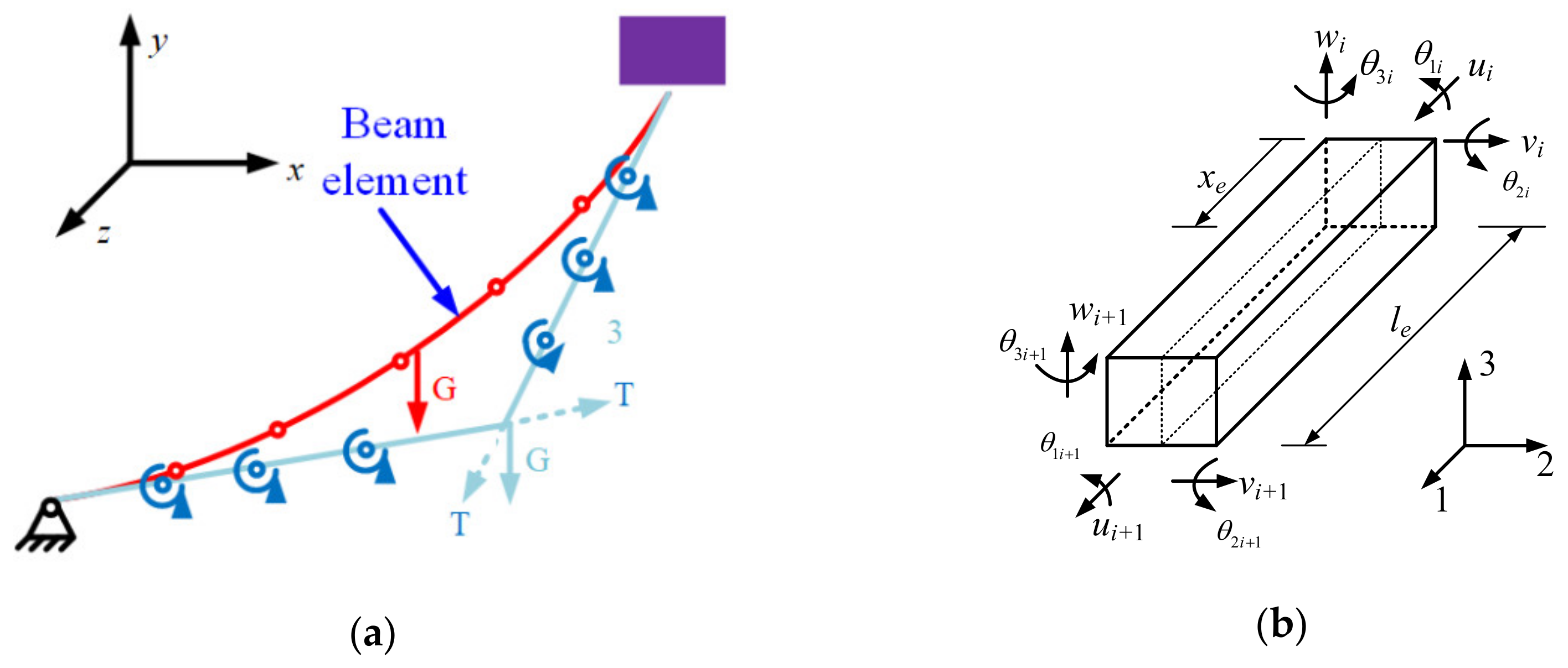
2.1. Governing Equations

Actually, the integrated floating wind turbine system, including blades, tower, spar, and mooring-lines, is a fully coupled and nonlinear system. Compared to the traditional quasi-static model, here, to include the dynamic effect of mooring-lines, i.e., the hysteresis behavior, a dynamic simulation model is developed using the coupled finite element method. Then, the mooring-lines hysteresis and its impacts on the global response of the spar floating wind turbine could be examined through our numerical simulations. The dynamic governing equation of the wind turbine system, in matrix form, can be written as:
M U ¨ + C U · + K U = F
where M, C, and K are, respectively, the mass matrix, damping matrix, and stiffness matrix of the wind turbine system, including the blades, tower, spar and catenary mooring-lines. U is the displacement vector, and F is the external load vector, including the wave forces acting on the spar and mooring-lines. As we know, the ocean wavelength is much larger than the diameters of the spar and mooring lines, so the hydrodynamic forces acting on the catenary mooring-line and spar can be calculated according to the Morison equation. It is very popular for slender structures and is expressed as:
f = 1 2 C D ρ D V U · ( V U · ) + C A π D 2 4 ρ ( V · U ¨ ) + π D 2 4 ρ V ·
where D is the diameter. CD and CA are the damping coefficient and added mass coefficient, respectively, and V is the velocity of the amid fluid.
In our FEM model, the governing equation, Equation (1), can be divided into three sets of equations, including the dynamic equations of the wind turbine, spar and mooring-lines, respectively:
M T U ¨ T + C T U · T + K T U T = F T M S U ¨ S + C S U · S + K S U S = F S M M U ¨ M + C M U · M + K M U M = F M
where the subscript T, S, and M denote wind turbine, spar and mooring-lines respectively. Considering that the stiffness of the floating spar is much larger than the tower and mooring lines, multipoint constraints are used to connect the bodies with large difference of the stiffness values here.
In order to simulate the non-linearity of the mooring-lines and predict its restoring force accurately, three-dimensional non-linear beam elements are used to model the mooring-lines, see Figure 1. Moreover, to simulate the special characteristics of a catenary mooring-line, the constraint of the rotational degrees of freedom of two connecting beam elements is released in the FEM model. In that case, the displacement vector of the beam element in the local coordinate system is
U e = [ u 1 j , u 2 j , u 3 j , θ 1 j , θ 2 j , θ 3 j , u 1 j + 1 , u 2 j + 1 , u 3 j + 1 , θ 1 j + 1 , θ 2 j + 1 , θ 3 j + 1 ]
where the direction 1 is along the longitude axle of the beam element, and direction 2 and 3 are lateral. j is the node number. Due to the additional rotation angle, the mooring-line model is statically indeterminate with a stronger stiffness singularity. Here, the original shape and top tension based on traditional static catenary theory are used as the definite conditions to eliminate the singularity of the stiffness matrix [13].
For the catenary-type mooring-lines, parts of the line may lay on the seabed. Under operational cases, the mooring-lines may fall down and eventually touch the seabed periodically, hence it is necessary to model the interaction between seabed and mooring-line. In the presented FEM model, some non-linear springs are used to model the supporting effect of the seabed, and the diagram is shown in Figure 2.
During the dynamic response, the nodes of the mooring-line elements that may touch seabed are connected with the nonlinear spring elements. Those springs can only provide forces in the y direction (Figure 2), and the values of the stiffness coefficients (k) are 0 and 1.0 × 10⁵ N/m for Y > 0 and Y ≤ 0, respectively. The value, 1.0 × 10⁵, is chosen so that the spring element is able to simulate the seabed action without causing matrix singularities. Additionally, Y represents the coordinate position of the upper node of each spring. When the mooring-line moves away from the seabed, the supporting force will be zero. On the contrary, the spring will take its supporting effect when the mooring-line touches down the seabed. As the effect of elastic support of the seabed is the main factor affecting the tension of mooring-lines, the bottom friction is not included here.

2.2. Non-Linear Mooring-Lines Model

The nonlinearity of mooring-lines comes from both geometry and nonlinear loads, in order to obtain the dynamic results with acceptable precision, the time step during the dynamic analysis should be small enough. To reduce the calculation cost and improve the calculation efficiency, the super-elements are applied for every single mooring-line of the three mooring-lines.
In the mooring line model, each mooring-line is processed as a set of super-elements; thus, the mooring-line is reduced to a boundary that provides restoring force for the spar float. The degrees-of-freedom (DOFs) for each super-element are partitioned into boundary/exterior DOFs and interior DOFs. A super-element’s exterior DOFs are described as those that are retained for further analysis, and the interior DOFs are condensed out of the matrices during the reduction process. Here the static mooring equation is used to illustrate the calculation process of the super-element. Considering a static equation as:
K f f U f f = F f f
The governing Equation (5) can be written as:
K e e K e i K e i K i i U e U i = F e F i
where Ue and Ui are the boundary and interior displacements, respectively. Then the reduced matrix equation is:
K e e * 0 K i e * I U e U i = F e * F i *
where the new stiffness matrix and load vector can be expressed as
K e e * = K e e K e i K i i 1 K i e , F e * = F e K e i K i i 1 F i K i e * = K i i 1 K i e , F i * = K i i 1 F i
It should be noted that the Gaussian–Jordan elimination method is applied to obtain Equation (7), and then the displacement vector Ue can be obtained using the first formula of Equation (7). Once the boundary solution is known, this boundary solution is used to calculate the interior displacements for each super-element, then the standard data recovery is available for all super-elements. The displacement vector of the interior nodes will be obtained by the second formula of Equation (7) as:
U i = F i * K i e * U e

2.3. Iteration Scheme during Dynamic Response

As the Newmark-beta method has no dissipation and works well for regular vibration problems, the Newmark-beta method is applied in this study to solve the nonlinear governing equations of the wind turbine system. The generalized form of the Newmark-beta operator is:
U t + Δ t = U t + U · t Δ t + 1 2 α U ¨ t + α U ¨ t + Δ t Δ t 2 U · t + Δ t = U · t + 1 β U ¨ t + β U ¨ t + Δ t Δ t
where ∆t is the time increment, and α and β are the integration constants. Using the two formulas in Equation (10) we can obtain that:
U ¨ t + Δ t = 1 α Δ t 2 U t + Δ t U t 1 α Δ t U · t 1 2 α 1 U ¨ t U · t + Δ t = U · t + 1 β Δ t U ¨ t + β Δ t U ¨ t + Δ t
The dynamic governing equation at time t + ∆t can be written as:
M U ¨ t + Δ t + C U · t + Δ t + K U t + Δ t = F t + Δ t
Substitute Equation (11) into Equation (12) derives:
K ¯ U t + Δ t = F ¯ t + Δ t
where
K ¯ = K + a 0 M + a 1 C F ¯ t + Δ t = F t + Δ t + M a 0 U t + a 2 U · t + a 3 U ¨ t + C a 1 U t + a 4 U · t + a 5 U ¨ t
and
a 0 = 1 α Δ t 2 a 1 = β α Δ t a 2 = 1 α Δ t a 3 = 1 2 α 1 a 4 = β α 1 a 5 = Δ t 2 β α 2
As we know the structural displacement, velocity, and acceleration at time t, the equivalent load vector at t + ∆t can be obtained by Equation (14). Then, the displacement at time step t + ∆t will be derived with Equation (13), and the velocity and acceleration vectors can be calculated by Equation (11) subsequently.

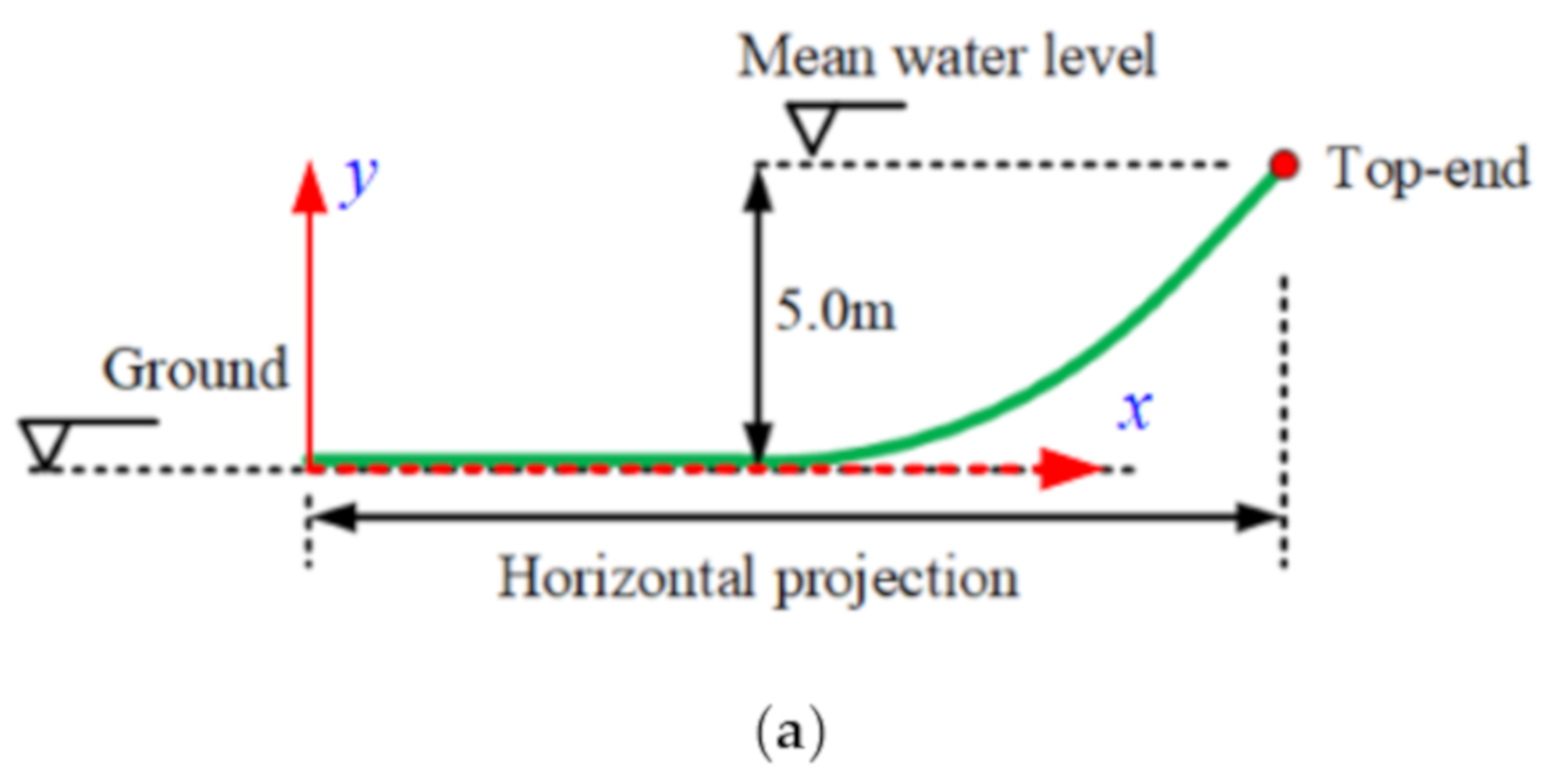
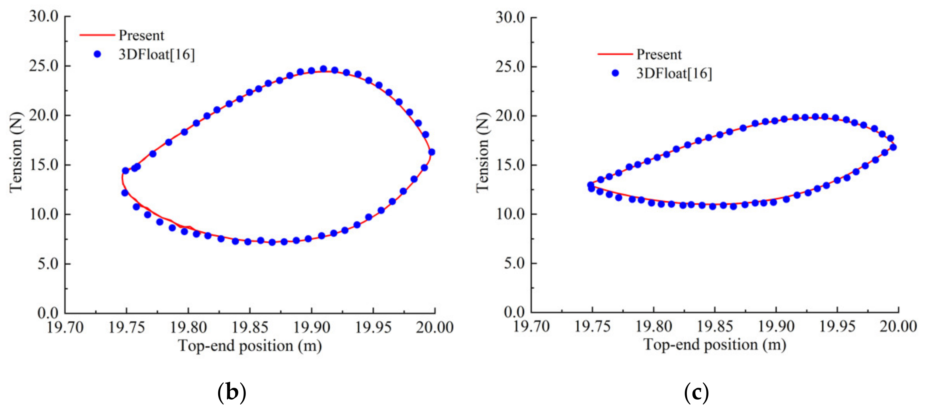
3. Model Verifications

3.1. Comparisons of Top Tension

To verify the established numerical model, the dynamic responses of a catenary mooring-line (Figure 3a) caused by top-end motion are calculated. The catenary parameters are listed in Table 1 [16], and top-end surge (x-direction, as shown in Figure 3a) is considered, of which the surge amplitude is 0.125 m, and surge periods are 3.16 s and 4.74 s. Figure 3b,c presents the comparison between the calculated top tensions and the results of 3DFloat [16], which is a code for the modelling of floating offshore wind turbines. Compared to 3DFloat, where the rotor is modelled as rigid with no interaction between the rotor and the tower, in our model, all the components, such as rotor and tower, are modelled as flexible bodies, and the coupling between these components can be included. From Figure 3, it can be seen that the predicted tensions agree well with 3DFloat, where the direction of the displacement-tension phase curves shown in Figure 3b,c are clockwise.

3.2. Verifications of the Coupled FEM Model

To verify the presented coupled FEM model, the global dynamic characteristics of the wind turbine are calculated, and the numerical frequencies and modes are compared with the experiments. A 5-MW wind turbine with a spar-type float is selected as the object here. The draft of the spar float is 120 m, and it is moored by three catenary mooring-lines. The schematic of the wind turbine model is shown in Figure 4, and the main parameters are listed in Table 2 [17,18]. For a spar-type floating wind turbine, the restoring forces in surge and sway directions are provided by the mooring-lines, and the restoring performance for pitch and roll motions depends on the dimension and mass distribution of the spar. This study mainly focuses on the surge and pitch motions of the spar.
The developed FE approach is applied to calculate the dynamic characteristics and responses. In the FEM model, the mooring-lines and tower are discrete by beam elements, and the spar is modeled as a rigid body with six DOFs. The nacelle and rotor are treated as a lumped mass. Considering its mass is small compared to the total mass of the whole wind turbine, this treatment is acceptable. Based on the developed FE (finite element) model, the global dynamic characteristics of the wind turbine are calculated and compared with the published results [19], as shown in Table 3. It can be seen that the predicted values agree well with the published ones, and the differences are less than 3%.

4. Structural Response and Result Discussions

To study the impacts of the mooring-lines hysteresis on the responses of spar-type floating wind turbines, only the regular wave loads are considered. Case one is regular wave conditions, and the significant wave height is 3 m and the wave period is 10 s. Case two is an extreme condition, with a 14.4 m significant wave height and 13.3 s wave period. Here, the initial condition is that all bodies are originally still. As for a comparison, the response of the spar with a quasi-static restoring force, where the dynamic effect cannot be considered, is also calculated.

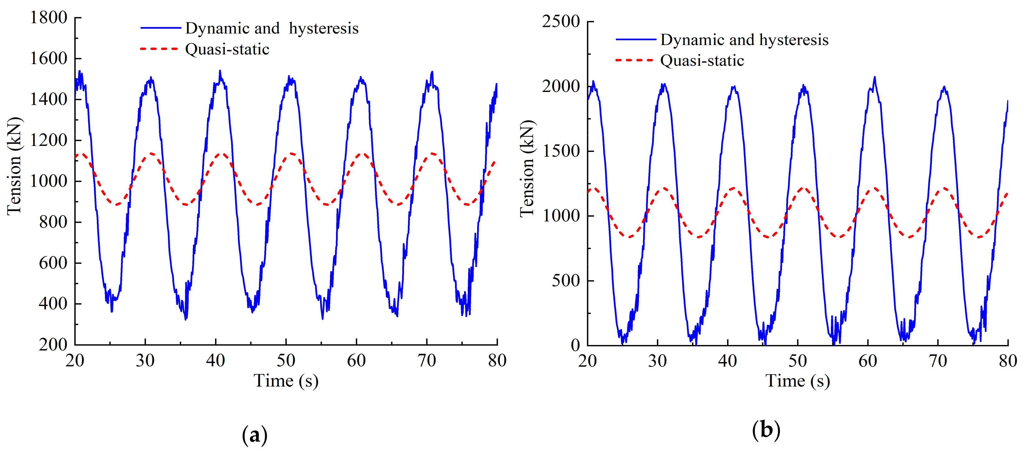
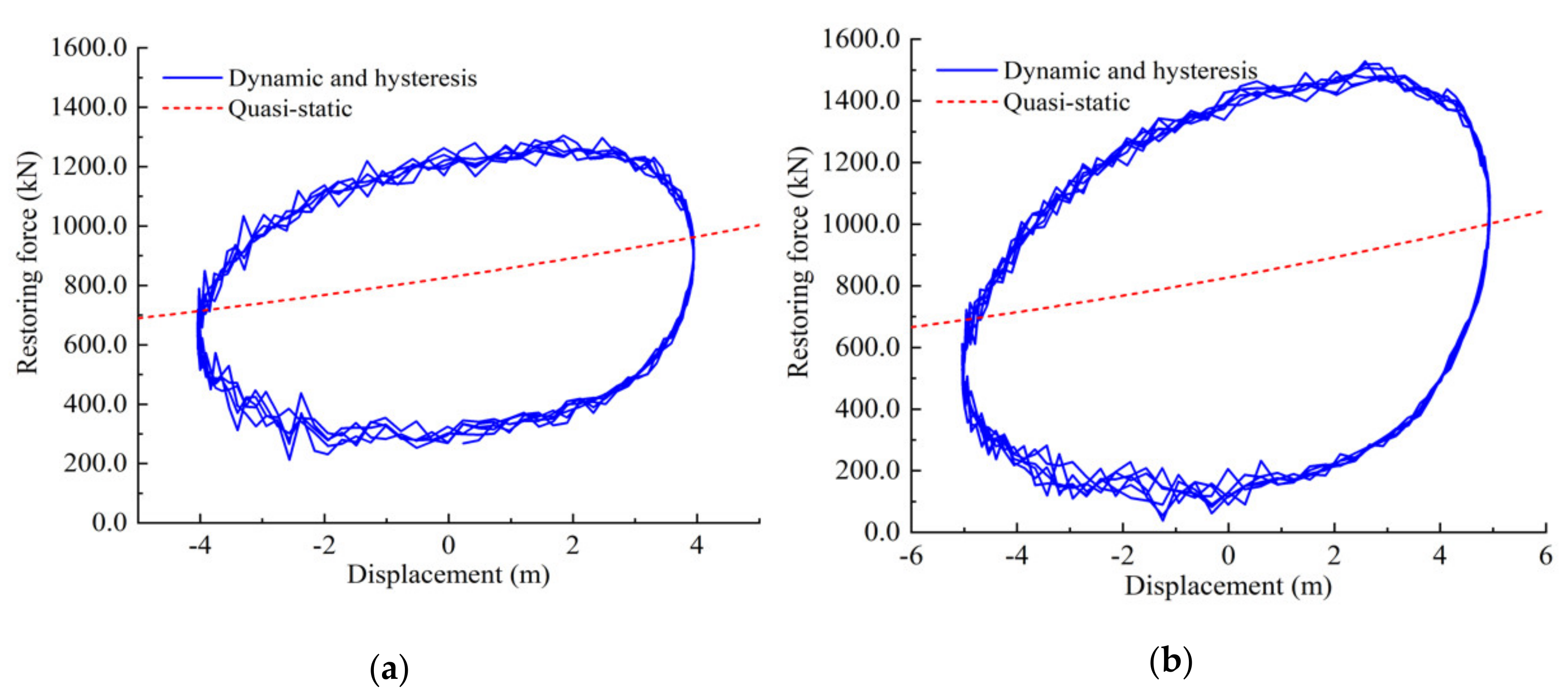
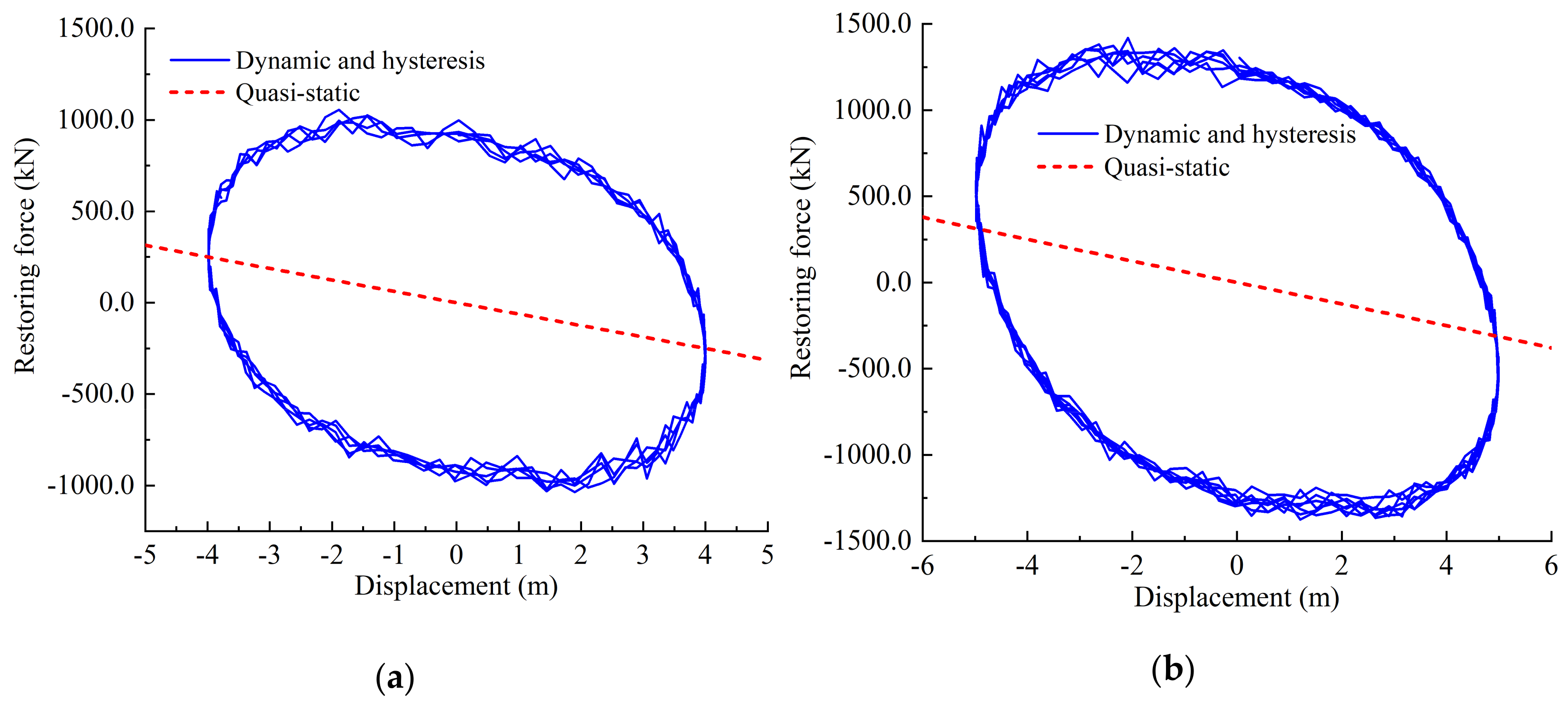
4.1. Hysteresis Behavior of Dynamic Mooring-Lines

The dynamic responses of a catenary mooring-line caused by the spar motion (spar surge in x-direction, as shown in Figure 4b) are calculated firstly in this section. As the environmental wave periods mainly range from 5 to 20 s, the frequency of spar surge is selected as 0.1 Hz, and three amplitudes, i.e., 4 m, 5 m, and 6 m, are considered. The mooring-line dynamics, i.e., the inertial and damping effects, along with the interaction between seabed and mooring-lines, are included in the numerical simulations.
The top tension series of Line 1 (Figure 4b) is shown in Figure 5. The tensions with its dynamics and hysteresis under consideration are compared with the quasi-static ones. It is seen that, owing to the mooring-line hysteresis, the tension gets larger, and it increases with the increase of the spar-surge amplitude. For example, the maximum tension and tension amplitude are respectively 1.6 and 5.3 times larger than the quasi-static values. It should also be noted that under large float movement, the mooring-line may slack, or the minimum tension is approaching zero, as shown in Figure 5b.
The restoring forces of a single catenary mooring-line are presented in Figure 6, and the quasi-static ones are also plotted for comparison. It can be seen that the restoring forces, considering mooring-line dynamics and hysteresis, become directionally dependent, and the maximum force gets much larger while the minimum value is much smaller than the quasi-static values.
Figure 7 shows the restoring stiffness curves of the whole mooring system (including the three mooring-lines shown in Figure 3), and the quasi-static restoring forces are also presented as a comparison. Similar to the result of the single mooring-line, the stiffness with dynamic and hysteresis behaves quite different from the static, which is directionally dependent on the spar velocities. And interestingly, the restoring force may be in the opposite direction, though the surge displacements are the same, e.g., when the spar displacement is 3.0 m, the corresponding restoring forces are −860 kN and 550 kN for two opposite velocity directions (Figure 7a). That is, the restoring force depends on not only the spar displacement but also the spar velocity. Moreover, due to the damping effect coming from the structure and the fluid of the mooring-line, the restoring force produces significant hysteresis, and the restoring stiffness curve shapes approximately as an ellipse loop.

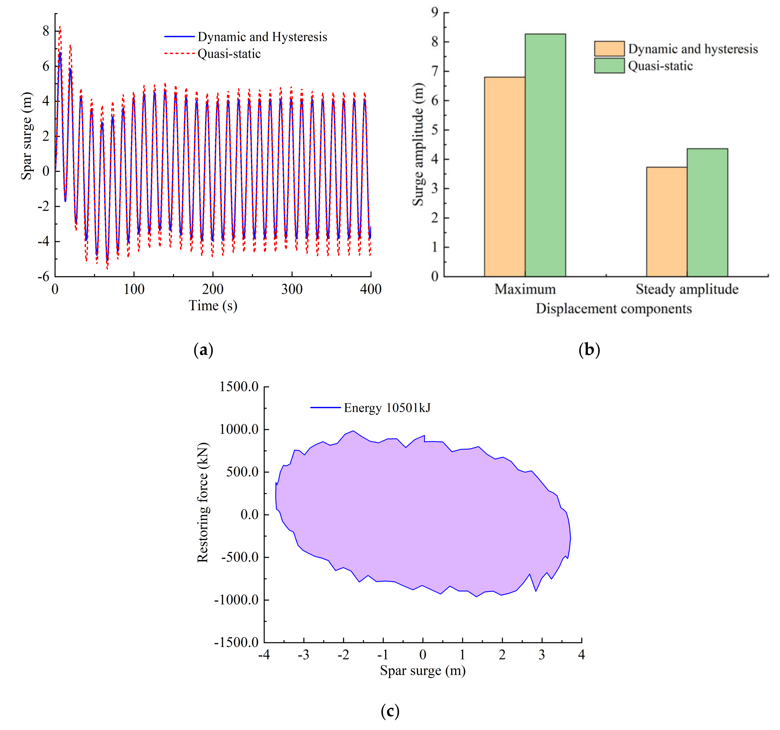
4.2. Impact of Restoring Hysteresis on Wind Turbine Response

In this section, two excitation frequencies with two wave heights are considered, i.e., the wave periods are 10 s and 13.3 s, and the corresponding wave heights are 3.0 m and 14.4 m, respectively. To evaluate the impacts of mooring-lines hysteresis on wind turbine responses, the responses under quasi-static restoring force are also calculated as a comparison. The dynamic responses of the wind turbine are simulated during 1000 s time duration, and the incident wave direction is along with the surge direction of the spar (x-direction, as shown in Figure 4b).
Under a regular wave load, the time histories of spar surge are plotted in Figure 8a. Due to the hysteresis of the mooring-lines, the maximum transient surge displacement becomes about 11.0% smaller, and the largest difference is around 62.8%, compared to the static case. Additionally, the Fourier transformation of the surge series is shown in Figure 8b, where the amplitude during the steady phase keeps almost the same. It means that the hysteresis behavior of mooring-lines has just a little influence on the steady-state of spar surge under the condition of a regular wave load.
As for the pitch motion shown in Figure 8c, the difference of displacement is very small during both transient and steady phases. The main reason might be that, for a spar-type float, the mooring-lines only provide restoring stiffness to transverse motions, e.g., surge, sway, and heave motions. Moreover, the restoring force to control pitch or roll motions is mainly provided by hydrostatic buoyancy and spar structural gravity.
Under extreme wave conditions, the time history of spar surge is presented in Figure 9a. It can be seen that mooring-lines hysteresis can reduce the surge displacement during both transient and steady states, compared to the quasi-static case. For example, the maximum displacement gets about 17.8% smaller, i.e., 6.8 m compared to 8.27 m; and the surge amplitude during the steady-state is about 14.4% smaller, i.e., 3.73 m compared to 4.36 m as shown in Figure 9b. The reason for this displacement decrease is that when the amplitude of spar surge gets larger, the hysteresis behavior of mooring-lines will consume the energy caused by extreme wave loading. Under extreme wave conditions, the energy consumption during one period is about 10,501 kJ (Figure 9c), thus leading to a decrease in the spar surge displacement.

5. Conclusions

In this study, using the coupled finite element method, a dynamic simulation model is developed to study the motion responses of a spar floating wind turbine under consideration of mooring-lines hysteresis. To simulate the large-amplitude motion and nonlinear behaviors of catenary mooring-lines, the FEM model is developed based on a combination of 3D nonlinear beam elements and a super-element approach, and the interaction between mooring-lines and seabed is also included. Based on the numerical model, the restoring performance of mooring-lines and its hysteresis behavior are studied. Further, the motion responses, e.g., the displacements of the spar float undergoing various wave loads, are examined. The numerical results show that:
(1)
The tensions with dynamic and hysteresis under consideration get larger with the increase of the spar surge amplitude, and the maximum tension and tension amplitude are, respectively, 1.6 and 5.3 times larger than the quasi-static one.
(2)
The restoring stiffness of the mooring-lines exhibits hysteresis behavior, and the restoring force is directionally dependent.
(3)
Due to the hysteresis behavior of the restoring performance, under extreme wave load conditions, the spar surge gets about 14.4% smaller compared with the quasi-static cases.

Author Contributions

Conceptualization and methodology, W.C., S.G. and Y.L.; model and validation, S.G. and Y.L.; writing—original draft preparation, W.C., S.G. and Y.L.; writing—review, Y.S. All authors have read and agreed to the published version of the manuscript.

Informed Consent Statement

Not applicable.

Acknowledgments

The authors of this paper would like to thank the financial supports provided by the research funding sponsored by The State Key Laboratory of Marine Resource Utilization in the South China Sea (Hainan University) (Grant No. MRUKF2021027) and the Strategic Priority Research Programme of the Chinese Academy of Sciences (Grant No. XDA22000000).

Conflicts of Interest

The authors declare no conflict of interest.

References

  1. Global Wind Report. Global Wind Energy Council. 2020. Available online: https://wfo-global.org/wp-content/uploads/2020/08/WFO_Global-Offshore-Wind-Report-HY1-2020.pdf (accessed on 1 December 2020).
  2. Han, Y.; Le, C.; Ding, H.; Cheng, Z.; Zhang, P. Stability and dynamic response analysis of a submerged tension leg platform for offshore wind turbines. Ocean Eng. 2017, 129, 68–82. [Google Scholar] [CrossRef]
  3. Zhang, H.; Liang, F.; Zheng, H. Dynamic impedance of monopiles for offshore wind turbines considering scour-hole dimensions. Appl. Ocean Res. 2021, 107, 102493. [Google Scholar] [CrossRef]
  4. Cao, G.; Chen, Z.; Wang, C.; Ding, X. Dynamic responses of offshore wind turbine considering soil nonlinearity and wind-wave load combinations. Ocean Eng. 2020, 217, 108155. [Google Scholar] [CrossRef]
  5. Chen, D.; Gao, P.; Huang, S.; Li, C.; Yu, X. Static and dynamic loading behavior of a hybrid foundation for offshore wind turbines. Mar. Struct. 2020, 71, 102727. [Google Scholar] [CrossRef]
  6. Kim, H.G.; Kim, B.J. Design Optimization of Conical Concrete Support Structure for Offshore Wind Turbine. Energies 2020, 13, 4876. [Google Scholar] [CrossRef]
  7. Zhang, R.; Tang, Y.; Hu, J.; Ruan, S.; Chen, C. Dynamic response in frequency and time domains of a floating foundation for offshore wind turbines. Ocean Eng. 2013, 60, 115–123. [Google Scholar] [CrossRef]
  8. Jeon, S.H.; Cho, Y.U.; Seo, M.W.; Cho, J.R.; Jeong, W.B. Dynamic response of floating substructure of spar-type offshore wind turbine with catenary mooring cables. Ocean Eng. 2013, 72, 356–364. [Google Scholar] [CrossRef]
  9. Tanaka, K.; Sato, I.; Utsunomiya, T.; Kakuya, H. Validation of dynamic response of a 2-MW hybrid-spar floating wind turbine during typhoon using full-scale field data. Ocean Eng. 2020, 218, 108262. [Google Scholar] [CrossRef]
  10. Ishihara, T.; Liu, Y. Dynamic Response Analysis of a Semi-Submersible Floating Wind Turbine in Combined Wave and Current Conditions Using Advanced Hydrodynamic Models. Energies 2020, 13, 5820. [Google Scholar] [CrossRef]
  11. Ferri, G.; Marino, E.; Borri, C. Optimal Dimensions of a Semisubmersible Floating Platform for a 10 MW Wind Turbine. Energies 2020, 13, 3092. [Google Scholar] [CrossRef]
  12. Matha, D.; Bischoff, O.; Fechter, U. Non-Linear Multi-Body Mooring System Model for Floating Offshore Wind Turbines. In Proceedings of the EWEA Offshore, Amsterdam, The Netherlands, 29 November–1 December 2011. [Google Scholar]
  13. Azcona, J.; Palacio, D.; Munduate, X.; González, L.; Nygaard, T.A. Impact of mooring lines dynamics on the fatigue and ultimate loads of three offshore floating wind turbines computed with IEC 61400-3 guideline. Wind Energy 2017, 20, 797–813. [Google Scholar] [CrossRef] [Green Version]
  14. Li, Y.; Guo, S.; Chen, W.; Yan, D.; Song, J. Analysis on restoring stiffness and its hysteresis behavior of slender catenary mooring-line. Ocean Eng. 2020, 209, 107521. [Google Scholar] [CrossRef]
  15. Li, Y.; Guo, S.; Kong, Y.; Li, M.; Chen, W. Non-Linearly Restoring Performance and its Hysteresis Behavior of Dynamic Catenary. In Proceedings of the ASME2019, International Conference on Ocean, Offshore and Arctic Engineering, Scotland, UK, 9–14 June 2019; Volume 58806, p. V05AT04A016. [Google Scholar]
  16. Azcona, J.; Munduate, X.; González, L.; Nygaard, T.A. Experimental validation of a dynamic mooring lines code with tension and motion measurements of a submerged chain. Ocean Eng. 2017, 129, 415–427. [Google Scholar] [CrossRef] [Green Version]
  17. Jonkman, J.M. Definition of the Floating System for Phase IV of OC3; National Renewable Energy Laboratory: Golden, CO, USA, 2010. [Google Scholar]
  18. Jonkman, J.M.; Butterfield, S.; Musial, W. Definition of a 5-MW Reference Wind Turbine for Offshore System Development; National Renewable Energy Laboratory: Golden, CO, USA, 2009. [Google Scholar]
  19. Karimirad, M. Modeling aspects of a floating wind turbine for coupled wave-wind-induced dynamic analyses. Renew. Energy 2013, 53, 299–305. [Google Scholar] [CrossRef]
Figure 1. Catenary mooring-line and 3D beam elements. (a) Schematic of catenary mooring-line; (b) 3D beam element.
Energies 14 02109 g001
Figure 2. Schematic diagram of mooring-seabed interaction.
Energies 14 02109 g002
Figure 3. Comparison of top tensions with two motion periods. (a) Diagram of catenary mooring-line; (b) Top-end period 3.16 s; (c) Top-end period 4.74 s.
Energies 14 02109 g003aEnergies 14 02109 g003b
Figure 4. Schematic of the floating wind turbine system. (a) The wind turbine model; (b) Schematic of mooring-line.
Energies 14 02109 g004
Figure 5. Comparisons of mooring-line tensions. (a) Spar surge amplitude 4 m; (b) Spar surge amplitude 6 m.
Energies 14 02109 g005
Figure 6. Restoring force of a single catenary mooring-line. (a) Spar surge amplitude 4 m; (b) Spar surge amplitude 6 m.
Energies 14 02109 g006
Figure 7. Restoring performance of the whole mooring system. (a) Spar surge amplitude 4 m; (b) Spar surge amplitude 6 m.
Energies 14 02109 g007
Figure 8. Surge and pitch response of the spar under regular wave force. (a) Time history of the spar surge; (b) Spectrum of spar surge; (c) Time history of the spar pitch.
Energies 14 02109 g008
Figure 9. Spar response and energy consumption mooring-lines under extreme wave conditions. (a) Time history of the spar surge; (b) Amplitudes of surge components; (c) Energy consumption during one period.
Energies 14 02109 g009
Table 1. The parameters of the second catenary mooring-line.
ParameterValueParameterValue
Total length21.0 mEquivalent hydrodynamic diameter0.0034 m
Initial horizontal projection19.872 mMass per unit length0.069 kg/m
Initial vertical projection5.0 mWet weight per unit length0.5872 N/m
Axial stiffness3.4 × 105 N
Table 2. The main parameters of the wind turbine system.
ParametersValueParametersValue
Tower height above water87.6 mMooring-line length904.0 m
Material density of tower8500.0 kg/m3Rotor diameter126.0 m
Depth to spar base below water120.0 mBlade length61.5 m
Spar total mass7,466,330.0 kgHub diameter3.0 m
Equivalent mooring-line weight in water698.1 N/mRated wind speed11.4 m/s
Depth to anchors below water320.0 mBlade mass17,740.0 kg
Horizontal projection mooring-lines853.0 m
Table 3. Natural periods of the wind turbine.
Wind Turbine ModesPredicted Value (s)Ref. [19] (s)Difference/%
Surge129.0125.62.7
Sway129.0125.62.7
Pitch28.028.51.79
Roll28.028.51.79
Publisher’s Note: MDPI stays neutral with regard to jurisdictional claims in published maps and institutional affiliations.

