Article

A Fibonacci Wavelet Method for Solving Dual-Phase-Lag Heat Transfer Model in Multi-Layer Skin Tissue during Hyperthermia Treatment

by
Hari Mohan Srivastava
1,2,3,*,
Mohd. Irfan
4 and
Firdous A. Shah
4
1
Department of Mathematics and Statistics, University of Victoria, Victoria, BC V8W 3R4, Canada
2
Department of Medical Research, China Medical University Hospital, China Medical University, Taichung 40402, Taiwan
3
Department of Mathematics and Informatics, Azerbaijan University, Baku AZ1007, Azerbaijan
4
Department of Mathematics, South Campus, University of Kashmir, Anantnag 192101, India
*
Author to whom correspondence should be addressed.
Energies 2021, 14(8), 2254; https://doi.org/10.3390/en14082254
Submission received: 3 February 2021 / Revised: 24 March 2021 / Accepted: 15 April 2021 / Published: 17 April 2021
(This article belongs to the Special Issue Numerical Simulation of Convective Heat Transfer)

Abstract

:
In this article, a novel wavelet collocation method based on Fibonacci wavelets is proposed to solve the dual-phase-lag (DPL) bioheat transfer model in multilayer skin tissues during hyperthermia treatment. Firstly, the Fibonacci polynomials and the corresponding wavelets along with their fundamental properties are briefly studied. Secondly, the operational matrices of integration for the Fibonacci wavelets are built by following the celebrated approach of Chen and Haiso. Thirdly, the proposed method is utilized to reduce the underlying DPL model into a system of algebraic equations, which has been solved using the Newton iteration method. Towards the culmination, the effect of different parameters including the tissue-wall temperature, time-lag due to heat flux, time-lag due to temperature gradient, blood perfusion, metabolic heat generation, heat loss due to diffusion of water, and boundary conditions of various kinds on multilayer skin tissues during hyperthermia treatment are briefly presented and all the outcomes are portrayed graphically.

1. Introduction

Cancer is the leading cause of death in the human population with an annual death rate of 10 million approximately. Consequently, ample research work has been devoted to study the cause and treatment of cancer in recent years [1]. In particular, hyperthermia treatment has proved to be very important and successful for cancer treatment [2]. During hyperthermia treatment, the temperature at the tumor site is increased by certain external heat sources including ultrasound waves, hot-water tubing, infrared radiation, radio-frequency, and several others [3,4]. As is well-known, the affected region (tumor) is always surrounded by healthy tissue, therefore, accurate information of the temperature distribution in the entire affected region plays a vital role during the treatment process. Recently, Romano et al. [5] investigated the effects of temperature and its potential role in pars plana vitrectomy and found that the variations in temperature during vitreoretinal surgery are clinically significant, as the rheology of tamponades can be better manipulated by modulating intraocular pressure and temperature. Moreover, they showed that rapid circulation of fluid in the vitreous cavity reduces the heat produced by the retinal and choroidal surface, bringing the temperature toward room temperature. However, the situation in multilayer skin tissue is even more complicated as the process involves different mechanisms such as heat conduction, water diffusion, vaporization, convection, and blood perfusion. Therefore, the proper modeling and analysis of treatment play an indispensable role in optimizing the temperature distribution in the affected region. This lead to the birth of several heat transfer models including the Wulff model [6], the Klinger model [7], the Cao-Yang-Srivastava model [8], the Chen-Holmes model [9], the Weinbaum-Jiji model [10], the Nakayama-Kuwahara model [11], and the Pennes bioheat transfer model [12].
Among all of the heat transfer models, the Pennes bioheat transfer model has received considerable attention mainly due to its simple and lucid nature, and is governed by Fourier’s law of heat conduction
q ( r , t ) = k T ( r , t ) ,
where T ( r , t ) and q denote the temperature gradient and heat flux at position r, respectively. The model (1) is somewhat unrealistic due to the assumption that the thermal disturbance propagates at an infinite speed. To overcome this infeasibility, Cattaneo and Vernotte [13,14] proposed a single-phase-lag (SPL) model by adding a phase-lag term to the time-variable t as
q ( r , t + τ q ) = k T ( r , t ) ,
where τ q is the thermal relaxation time between heat flux and temperature gradient, which captures the microscale responses in time due to heat flux. One of the major drawbacks of the SPL model (2) is that it captures only the heat flux microstructural response but fails to capture the temperature gradient microstructural response. To overcome this issue, Tzou [15] proposed a dual-phase-lag model by introducing another phase-lag term τ t to the space variable of the SPL model (2) to get a substantial bioheat transfer model of the following form:
q ( r , t + τ q ) = k T ( r , t + τ t ) ,
where the parameters k , τ q , τ t , r , t , and T represent the thermal conductivity of the tissue, phase-lag due to heat flux, phase-lag due to temperature gradient, space coordinate, time, and tissue temperature, respectively. The significance of this model is that the heat propagates with a finite speed with two different relaxation times: one due to heat flux and the other one due to temperature gradient. Since its origin, this model has been proved to be of substantial importance for acquiring an insight into the mechanism underlying the process of heat transfer in living tissues. Finding the analytical and numerical solutions of the DPL model (3) is one of the prime research areas in mathematical, biological, and thermal sciences. Some of the commonly employed numerical techniques for obtaining the solution of model (3) include the finite volume method [16], the Laplace transform method [17], the boundary element method [18], the finite difference-decomposition method [19], the Adomian decomposition method [20], and the B-spline method [21].
Some of the compelling alternatives of the aforementioned numerical techniques include the wavelet-based numerical methods. Due to their simple procedure, easy computation, and rapid convergence, these methods have achieved a significant place in numerical analysis and approximation theory [22,23]. Some of the commonly used wavelet families for solving different physical, engineering, and biological problems include Haar wavelets, Legendre wavelets, Laguerre wavelets, Chebyshev wavelets, harmonic wavelets, Euler wavelets, Bernoulli wavelets, and ultraspherical wavelets. A recent addition to the class of wavelet families is the Fibonacci wavelets, which have attained considerable attention from researchers working across various disciplines in physical and engineering sciences, mainly due to their several distinguishing features [24,25]. For instance, these wavelets are not based on orthogonal polynomials, however, one can differentiate and integrate these wavelets to obtain the corresponding operational matrices. In addition to this, the Fibonacci wavelets are generated from the Fibonacci polynomials, which contain fewer terms in comparison to the shifted Legendre polynomials, which in turn speeds up the computational process and minimizes the computational errors [26].
With the pleasant characteristics of the Fibonacci wavelets in hindsight, we are profoundly motivated to introduce a new wavelet method based on nonorthogonal Fibonacci polynomials to solve the dual-phase-lag model of the bioheat transfer DPL model in multilayer skin tissue stratified as epidermis, dermis, and subcutaneous under the general boundary conditions. Moreover, we studied the effect of various parameters such as blood perfusion, tissue wall temperature, metabolic heat generation, and heat loss due to diffusion of water in multilayer skin tissue at the location of tumor. The obtained results shows that the proposed method is an appropriate tool for the approximation of smooth and piecewise smooth functions. Following the strategy of Chen and Haiso [27], we construct operational matrices of integration associated with the Fibonacci wavelets, which have less errors in comparison to the operational matrices based on Legendre wavelets [24]. The operational matrices of integration are then employed for converting the models at hand into a system of algebraic equations, which are subsequently solved by the usual Newton method. We studied the DPL model under different boundary conditions using the classical Haar wavelets in [28], however, the spirit of this study is completely different from the aforementioned study in the sense that (i) our method completely relies on the nonorthogonal Fibonacci wavelets generated via Fibonacci polynomials of degree m, (ii) multilayer skin tissues have been considered, (iii) investigation of the effect of volumetric heat loss due to water vaporization has also been studied.
The remainder of the article is structured as follows. In Section 2, we present the mathematical formulation of the model under consideration. Section 3 is completely devoted to the construction of Fibonacci wavelets and their operational matrices of integration. The solution of the DPL model is presented in Section 4. In Section 5, we discuss the obtained numerical results. Finally, a conclusion is drawn in Section 6.

2. Mathematical Formulation of the Model

As is known, the human skin tissue constitutes three different layers: epidermis, dermis, and subcutaneous layer (see Figure 1). Throughout this study, we shall consider the skin tissue of length L = 0.012 . The initial temperature inside the living biological skin tissue is taken as a constant temperature, i.e., T 0 = 37 C. The Fourier’s model of heat transfer for different layers of skin tissue is given by [29,30].
Epidermis Layer:
ρ c p T ( r , t ) t = k 2 T ( r , t ) + Q m + Q r Q v Q d .
Dermis Layer:
ρ c p T ( r , t ) t = k 2 T ( r , t ) + ρ b W b C p b T b T ( r , t ) + Q m + Q r Q d .
Subcutaneous Layer:
ρ c p T ( r , t ) t = k 2 T ( r , t ) + ρ b W b C p b T b T ( r , t ) + Q m + Q r Q d .
After applying the phase-lag in both the time and space of the Fourier’s model of multilayer tissue, we shall obtain the following DPL models of bioheat transfer for multilayer skin tissue as follows:
Epidermis Layer:
τ q ρ c p 2 T ( r , t ) t 2 τ q Q m t + τ q Q d t + ρ c p T ( r , t ) t = k 2 T ( r , t ) + τ t T ( r , t ) t + Q m + Q r Q v Q d .
Dermis Layer:
τ q ρ c p 2 T ( r , t ) t 2 τ q Q m t + τ q Q d t + ρ c p T ( r , t ) t + τ q ρ b W b C p b T ( r , t ) t = k 2 T ( r , t ) + τ t T ( r , t ) t + ρ b W b C p b T b T ( r , t ) + Q m + Q r Q d .
The initial condition is
T ( r , 0 ) = T 0 , T ( r , 0 ) t = 0
and the generalized boundary condition is
A 0 r T ( 0 , t ) + τ t T ( 0 , t ) t + B 0 T ( 0 , t ) = f ( t ) ,
where in the
BC of the first kind— A 0 = 0 , B 0 = 1 , f ( t ) = T w ;
BC of the second kind— A 0 = k , B 0 = 0 , f ( t ) = q w ;
BC of the third kind— A 0 = k , B 0 = h , f ( t ) = h T s ;
and the corresponding symmetric condition reads
r T ( L , t ) + τ t T ( L , t ) t = 0 .
The external heat source term, which is considered as a Gaussian distribution heat source term is given by [31,32]
Q r = Q r o e a o ( r i r * ) 2 ,
where Q r o = ρ S P , P , S , r * , and a o represent the transmitted power, antenna constant, location of tumor, and scattering variable, respectively. Moreover, the metabolic heat generation in skin tissue is defined by [32]
Q m = Q m o 1 + ( T ( r , t ) T 0 ) 10 , Q d = D f c p w ( ρ s ρ c ) ( r ) 2 ( T ( r , t ) T 0 ) ,
Q v = Δ m Δ H v a p δ c , Δ m = D v M w R a δ c P w T w s P w T w a R H ,
where Q m o , Q d , Q v , Δ m , and Δ H represent the constant metabolic heat, volumetric heat loss due to water diffusion, volumetric heat loss due to water vaporization, water vaporization rate of skin surface, and enthalpy of water vaporization, respectively [30]. In addition to this, some thermophysical parameters of the multilayer skin tissue are listed in Table 1 of Section 5 with their given values [30].
Consider the dimensionless variables given by
θ = T T 0 T 0 , θ b = T b T 0 T 0 , θ w = T w T 0 T 0 , η = k t ρ c p L 2 , ζ i = r i L , ζ * = r * L , F o q = k τ q ρ c p L 2 , F o t = k τ t ρ c p L 2 , P f = w b c p b ρ b k L , P m o = Q m o k T 0 L 2 , P r = ρ S P k T 0 L 2 , Q v o = Δ m Δ H v a p δ c L 2 k T 0 , Q d o = D f c p w ( ρ s ρ c ) ( r ) 2 L 2 k , K i = q w L k T 0 , B i = h L k , A * = A 0 T 0 L , B * = B 0 T 0 , g ( η ) = f ( t ) + B 0 T 0 . .
Subsequently, all of the models (7) to (12) are converted into the following dimensionless form:
Epidermis Layer:
F o q 2 θ η 2 + 1 F o q α P m o + F o q Q d o θ η = 2 ζ 2 θ + F o t θ η + α P m o Q d o θ + P m Q v o + P r e a 0 ( ζ i ζ * ) 2 .
Dermis Layer:
F o q 2 θ η 2 + 1 F o q α P m o + F o q Q d o + F o q P f 2 θ η = 2 ζ 2 θ + F o t θ η + α P m o Q d o P f 2 θ + P m + P f 2 θ b + P r e a 0 ( ζ i ζ * ) 2 .
Subcutaneous Layer:
F o q 2 θ η 2 + 1 F o q α P m o + F o q Q d o + F o q P f 2 θ η = 2 ζ 2 θ + F o t θ η + α P m o Q d o P f 2 θ + P m + P f 2 θ b + P r e a 0 ( ζ i ζ * ) 2 .
The initial condition is given by
θ ( ζ , 0 ) = 0 , θ ( ζ , 0 ) η = 0 ,
the generalized boundary condition is given by
A * ζ θ ( 0 , η ) + F o t θ ( 0 , η ) η + B * θ ( 0 , η ) = g ( η ) ,
where we have the following conditions:
In the BC of the first kind: A * = 0 , B * = 1 , g ( η ) = θ w ,
θ ( 0 , η ) = θ w .
In the BC of the second kind: A * = 1 , B * = 0 , g ( η ) = K i ,
θ ( 0 , η ) ζ = K i ( 1 e η F o t ) .
In the BC of the third kind: A * = 1 , B * = B i , g ( η ) = B i θ s ,
θ ( 0 , η ) ζ = B i ( θ θ ( 0 , η ) ) ( 1 e η F o t ) ,
together the following corresponding symmetric condition:
ζ θ ( 1 , η ) + F o t θ ( 1 , η ) η = 0 .
It is worth noticing that the DPL models of bioheat transfer for multilayer skin tissue (17)–(19) reduce to SPL models for multilayer skin tissue by setting τ t = 0 and to classical Pennes bioheat models for multilayer skin tissue by setting τ q = τ t = 0 .

3. Fibonacci Wavelets and Operational Matrices of Integration

The aim of this section is two-fold: First, to provide an exposition to the construction of Fibonacci wavelets via Fibonacci polynomials; second, to derive the corresponding operational matrices of integration by adopting the strategy of Chen and Haiso [27].

3.1. Fibonacci Wavelets and Function Approximation

For any η R + , the Fibonacci polynomials are defined in terms of the recurrence relation as
P ˜ m + 2 ( η ) = η P ˜ m + 1 ( η ) + P ˜ m ( η ) ( m 0 ) ,
with initial conditions P ˜ 0 ( η ) = 0 , P ˜ 1 ( η ) = 1 [24]. Equivalently, they can be defined by using the following general formula:
P ˜ m ( η ) = 0 , m = 0 , 1 , m = 1 , η P ˜ m 1 ( η ) + P ˜ m 2 ( η ) , m > 1 ,
and the closed-form formula
P ˜ m 1 ( η ) = α m β m α β ( m 1 ) ,
where α and β are the roots of the companion polynomial x 2 η x 1 of the recursion. Furthermore, the power-form representation of the Fibonacci polynomials follows as in [26]:
P ˜ m ( η ) = i = 0 m / 2 m i i η m 2 i ( m 0 ) ,
where · denotes the well-known floor function. The Fibonacci polynomials P ˜ m ( η ) can also be expressed in the matrix form as follows:
P ˜ ( η ) = U L ( η ) ,
where
P ˜ ( η ) = P ˜ 0 ( η ) , P ˜ 1 ( η ) , P ˜ 2 ( η ) , T , d L ( η ) = 1 , η , η 2 , η 3 , T , and U = 1 0 0 0 0 0 0 0 1 0 0 0 0 0 1 0 1 0 0 0 0 0 2 0 1 0 0 0 1 0 3 0 1 0 0 0 3 0 4 0 1 0 1 0 6 0 5 0 1 .
It is worth noticing that the Fibonacci polynomials satisfies the following properties:
0 η P ˜ m ( s ) d s = 1 m + 1 P ˜ m + 1 ( η ) + P ˜ m 1 ( η ) P ˜ m + 1 ( 0 ) + P ˜ m 1 ( 0 ) ,
0 1 P ˜ m ( η ) P ˜ n ( η ) d η = i = 0 m / 2 j = 0 n / 2 m i i m j j 1 m + n 2 i 2 j + 1 .
The Fibonacci wavelets belong to a special class of the compactly-supported wavelets generated by the Fibonacci polynomials on [ 0 , 1 ] . Mathematically, the Fibonacci wavelets are defined on the interval [ 0 , 1 ] as follows (see [24]):
ϕ n , m ( η ) = 2 ( k 1 ) / 2 w m P ˜ m 2 k 1 η n + 1 , n 1 2 k 1 η < n 2 k 1 0 , otherwise ,
where P ˜ m ( η ) is the Fibonacci polynomial of degree m given by (28), and k and n denote the level of resolution k = 1 , 2 , and translation parameter n = 1 , 2 , , 2 k 1 , respectively. The coefficient 1 / w m appearing in (33) is a normalization factor and can be computed via (32) as follows:
w m = 0 1 P ˜ m 2 ( η ) d η ( m = 0 , 1 , , M 1 ) .
The Fibonacci wavelets (33) can also be represented as given below:
ϕ n , m ( η ) = 2 ( k 1 ) / 2 w m P ˜ m 2 k 1 η n + 1 χ I n , k ( η ) ,
where χ I n , k ( η ) is the characteristic function defined on n 1 2 k 1 , n 2 k 1 .
For the choice k = 2 and M = 3 , we have the following family of Fibonacci wavelets:
ϕ 1 , 0 ( η ) = 2 , ϕ 1 , 1 ( η ) = 2 6 η , ϕ 1 , 2 ( η ) = 15 14 ( 1 + 4 η 2 ) , , 0 η < 1 2 , ϕ 2 , 0 ( η ) = 2 , ϕ 2 , 1 ( η ) = 6 ( 2 η 1 ) , ϕ 2 , 2 ( η ) = 30 7 2 η 2 2 η + 1 , , 1 2 η < 1 . .
Therefore, any square integrable function f L 2 [ 0 , 1 ] can be approximated via the Fibonacci wavelets as follows:
f ( η ) f k , M ( η ) = n = 1 2 k 1 m = 0 M 1 h n , m ϕ n , m ( η ) ,
where h n , m denotes the Fibonacci wavelet coefficients. The matrix analogue of (37) reads as given below:
F = H T Φ ( η ) ,
where F is the discrete version of the continuous function f ( η ) and H is the row vector of the form
H = h 1 , 0 , h 1 , 1 , , h 1 , M 1 , h 2 , 0 , h 2 , 1 , , h 2 , M 1 , , h 2 k 1 , 0 , h 2 k 1 , 1 , , h 2 k 1 , M 1 T .
The matrix Φ ( η ) appearing in (38) is the Fibonacci wavelet matrix of order 1 × 2 k 1 M and is given by
Φ ( η ) = ϕ 1 , 0 , ϕ 1 , 1 , , ϕ 1 , M 1 , ϕ 2 , 0 , ϕ 2 , 1 , , ϕ 2 , M 1 , , ϕ 2 k 1 , 0 , ϕ 2 k 1 , 1 , , ϕ 2 k 1 , M 1 T .
The coefficient vector H can be obtained as follows:
H T = F T C 1 ,
where
C = Φ , Φ = 0 1 Φ ( η ) Φ T ( η ) d η , F = f n , m , f n , m = f , ϕ n , m .
For obtaining the Fibonacci wavelet approximations, we consider the following collocation points:
η = 2 1 2 k M , = 1 , 2 , , 2 k 1 M .

3.2. Operational Matrices of Fibonacci Wavelets

In this subsection, our endeavour is to construct operational matrices of integration for the Fibonacci wavelets (33) by following the strategy of Chen and Haiso [27]:
0 η Φ n , m ( σ ) d σ S Φ n , m ( η ) ,
where S is referred to as the Fibonacci wavelet operational matrix of order 2 k 1 M × 2 k 1 M . Using the power representation (28) and (35) of Fibonacci polynomials and wavelets along with the binomial expansion for 2 k 1 η n + 1 m 2 i , we have
ϕ n , m ( η ) = 2 ( k 1 ) / 2 w m i = 0 m / 2 m i i 2 k 1 η n + 1 m 2 i χ n 1 2 k 1 , n 2 k 1 ( η ) = 2 ( k 1 ) / 2 w m i = 0 m / 2 j = 0 m 2 i m i i 2 k j j η j 1 n m 2 i j χ n 1 2 k 1 , n 2 k 1 ( η ) .
Upon integration in (45), we obtain
0 η ϕ n , m ( σ ) d σ = 2 ( k 1 ) / 2 w m i = 0 m / 2 j = 0 m 2 i m i i 2 k j j η j 1 n m 2 i j 0 η σ j χ n 1 2 k 1 , n 2 k 1 ( σ ) d σ , = 2 ( k 1 ) / 2 w m i = 0 m / 2 j = 0 m 2 i m i i 2 k j j η j 1 n m 2 i j R j ( η ) ,
where
R j ( η ) = 0 η σ j χ n 1 2 k 1 , n 2 k 1 ( σ ) d σ , = n 1 2 k 1 η σ j χ n 1 2 k 1 , n 2 k 1 ( η ) d σ + n 1 2 k 1 n 2 k 1 σ j χ n 2 k 1 , 1 ( η ) d σ , 0 j m 2 i .
The function R j ( η ) can be expressed in terms of Fibonacci wavelets as follows:
R j ( η ) = r = 1 2 k 1 s = 0 M 1 β r , s ϕ r , s ( η ) .
Therefore, Equation (46) becomes
0 η ϕ n , m ( σ ) d σ = r = 1 2 k 1 s = 0 M 1 Γ r , s n , m ϕ r , s ( η ) ,
where
Γ r , s n , m = 2 ( k 1 ) / 2 w m i = 0 m / 2 j = 0 m 2 i m i i 2 k j j η j 1 n m 2 i j β r , s .
Therefore, the operational matrix of integration S for Fibonacci wavelets is formulated as given below:
S = Γ 1 , 0 1 , 0 Γ 1 , 1 1 , 0 Γ 2 k 1 , M 1 1 , 0 Γ 1 , 1 1 , 0 Γ 1 , 1 1 , 1 Γ 2 k 1 , M 1 1 , 1 Γ 1 , 0 2 k 1 , M 1 Γ 1 , 1 2 k 1 , M 1 Γ 2 k 1 , M 1 2 k 1 , M 1 .
For instance, if we consider k = 2 , M = 3 , we can integrate (36) at the collocation points given by (43) so that
0 η ϕ 1 , 0 ( σ ) d σ = 0 , 3 6 , 0 , 1 2 , 0 , 0 T Φ 6 × 6 ( η ) , 0 η ϕ 1 , 1 ( σ ) d σ = 3 4 , 0 , 35 10 , 3 4 , 0 , 0 T Φ 6 × 6 ( η ) , 0 η ϕ 1 , 2 ( σ ) d σ = 29 105 1680 , 35 35 , 1 4 , 5 21 , 0 , 0 T Φ 6 × 6 ( η ) , 0 η ϕ 2 , 0 ( σ ) d σ = 0 , 0 , 0 , 0 , 3 6 , 0 T Φ 6 × 6 ( η ) , 0 η ϕ 2 , 1 ( σ ) d σ = 0 , 0 , 0 , 3 4 , 0 , 35 10 T Φ 6 × 6 ( η ) , 0 η ϕ 2 , 2 ( σ ) d σ = 0 , 0 , 0 , 29 105 1680 , 35 35 , 1 4 T Φ 6 × 6 ( η ) .
Therefore, (44) takes the following form:
0 η Φ 6 × 1 ( σ ) d σ S 6 × 6 Φ 6 ( η ) ,
where
S 6 × 6 = 0 3 6 0 1 2 0 0 3 4 0 35 10 3 4 0 0 29 105 1680 35 35 1 4 5 21 0 0 0 0 0 0 3 6 0 0 0 0 3 4 0 35 10 0 0 0 29 105 1680 35 35 1 4 .

4. Solution of the Dual-Phase Model

The present section is devoted to the solving of the dual-phase-lag model of heat transfer in multilayer skin tissue during hyperthermia treatment by employing the Fibonacci wavelet operational matrices of integration constructed in Section 3. However, we shall first employ the finite difference scheme for discretizing the space variable ζ so that the given problem is converted into a system of ordinary differential equations.

4.1. Discretizing the Space Variable ζ

In order to curtail the complexity in the DPL models of multilayer skin tissue (17)–(19), we discretize the space coordinate ζ with the aid of the finite difference scheme by taking grid size Δ ζ = h = 1 / k , so that the points ζ = h , = 1 , 2 , , k , represent the grid points of the space interval [ 0 , 1 ] . Subsequently, the discrete values of the function θ ( ζ ) at the grid points ζ becomes θ ( ζ ) = θ ( ζ , η ) , for η 0 . Further, the application of the four-point formula at the boundary points yields (see [33])
d θ d ζ | ζ = 0 = 21 θ 0 + 13 θ 1 + 17 θ 2 9 θ 3 20 h
d θ d ζ | ζ = 1 = 21 θ k + 1 13 θ k 17 θ k 1 + 9 θ k 2 20 h .
Similarly, the implementation of the central difference scheme for second-order derivative reduces the DPL models (17) to (19) to the following matrix form:
Epidermis Layer:
F o q d 2 θ ( η ) d η 2 + 1 F o q α P m o + F o q Q d o d θ ( η ) d η = M θ ( η ) + F o t M d θ ( η ) d η + α P m o Q d o θ ( η ) + N 1 .
Dermis Layer:
F o q d 2 θ ( η ) d η 2 + 1 F o q α P m o + F o q Q d o + F o q P f 2 d θ ( η ) d η = M θ ( η ) + F o t M d θ ( η ) d η + α P m o Q d o P f 2 θ ( η ) + N 2 .
Subcutaneous Layer:
F o q d 2 θ ( η ) d η 2 + 1 F o q α P m o + F o q Q d o + F o q P f 2 d θ ( η ) d η = M θ ( η ) + F o t M d θ ( η ) d η + α P m o Q d o P f 2 θ ( η ) + N 3 ,
with initial condition
θ ( 0 ) = 0 , 0 , , 0 T , d θ ( 0 ) d η = 0 , 0 , , 0 T , and
M = M i i = 1 , for BC of the first kind i = 2 , for BC of the sec ond kind i = 3 , for BC of the third kind ,
where M i and N i , i = 1 , 2 , 3 are the matrices of order k × k and k × 1 , given by
M 1 = 1 h 2 2 1 0 0 0 0 1 2 1 0 0 0 0 1 2 0 0 0 0 0 0 1 2 1 0 0 0 9 21 38 21 29 21 ,
M 2 = 1 h 2 29 21 38 21 9 21 0 0 0 1 2 1 0 0 0 0 1 2 0 0 0 0 0 0 1 2 1 0 0 0 9 21 38 21 29 21 ,
M 3 = 1 h 2 29 21 38 21 9 21 0 0 0 1 2 1 0 0 0 0 1 2 0 0 0 0 0 0 1 2 1 0 0 0 9 21 38 21 29 21 ,
and
N 1 = P m o Q v o + F i ( η ) h 2 + P r e a o ( ζ 1 ζ * ) 2 , P m o Q v o + P r e a o ( ζ 2 ζ * ) 2 , , P m o Q v o + P r e a o ( ζ k ζ * ) 2 T ,
N 2 = P m o + P f 2 θ b + F i ( η ) h 2 + P r e a o ( ζ 1 ζ * ) 2 , P m o + P f 2 θ b + P r e a o ( ζ 2 ζ * ) 2 , , P m o + P f 2 θ b + P r e a o ( ζ k ζ * ) 2 T ,
N 3 = P m o + P f 2 θ b + F i ( η ) h 2 + P r e a o ( ζ 1 ζ * ) 2 , P m o + P f 2 θ b + P r e a o ( ζ 2 ζ * ) 2 , , P m o + P f 2 θ b + P r e a o ( ζ k ζ * ) 2 T ,
where
F i ( η ) = θ w , i = 1 , for BC of the first kind 20 h K i ( 1 e η F o t ) 21 , i = 2 , for BC of the sec ond kind 20 h B i ( θ s θ ( 0 , η ) ) ( 1 e η F o t ) 21 , i = 3 , for BC of the third kind .

4.2. Implementation of the Fibonacci Wavelets

The aim of this subsection is to solve the dual-phase-lag models of multilayer tissue by implementing the Fibonacci wavelet operational matrix method described in the previous section.
The highest derivative d 2 θ ( η ) d η 2 appearing in (56) to (58) can be expanded in terms of the Fibonacci wavelet as
d 2 θ ( η ) d η 2 = = 1 2 k 1 M h ϕ ( η ) = H y T Φ ( η ) ,
where y = 1 , 2 , and 3 are indicated for multilayer tissues such as the epidermis, dermis, and subcutaneous layers, respectively. Integration of Equation (68) between the limits 0 to η and using the initial condition (59) yields
d θ ( η ) d η = = 1 2 k 1 M h S , 1 ( η ) + d θ ( 0 ) d η = H y T S 1 ( η ) .
Once again, integrating (69) and using the same condition, we get
θ ( η ) = = 1 2 k 1 M h S , 2 ( η ) + η d θ ( 0 ) d η + θ ( 0 ) = H y T S 2 ( η ) .
Substituting the values of d 2 θ ( η ) / d η 2 , d θ ( η ) / d η , and θ ( η ) in Equations (56)–(58), we obtain the following systems of algebraic equations for epidermis, dermis, and subcutaneous layers, respectively:
Epidermis Layer:
H 1 T F o q Φ ( η ) + 1 F o q α P m o + F o q Q d o S 1 ( η ) α P m o Q d o S 2 ( η ) = H 1 T M S 2 ( η ) + F o t S 1 ( η ) + N 1 .
Dermis Layer:
H 2 T F o q Φ ( η ) + 1 F o q α P m o + F o q Q d o + F o q P f 2 S 1 ( η ) α P m o Q d o P f 2 S 2 ( η ) = H 2 T M S 2 ( η ) + F o t S 1 ( η ) + N 2 .
Subcutaneous Layer:
H 3 T F o q Φ ( η ) + 1 F o q α P m o + F o q Q d o + F o q P f 2 S 1 ( η ) α P m o Q d o P f 2 S 2 ( η ) = H 3 T M S 2 ( η ) + F o t S 1 ( η ) + N 3 .
Solving the above systems of algebraic Equations (71)–(73), we can obtain the unknown Fibonacci wavelet coefficient vector H y T . Finally, substituting the values of H y T in (70), we obtain the approximate solution of the dual-phase-lag model of multilayer tissue.

5. Numerical Results and Discussion

During hyperthermia treatment, the temperature is raised between 41–46 C for 15–30 min at the location of the tumor so that the cancer cells become dead without causing any damage to the healthy tissue. To check that the temperature distribution does not surpass 46 C in the multilayer skin tissue, some thermophysical properties of skin tissue are required for treatment of the tumor. Some of the selected properties of skin tissue are T 0 = T b = T w = 37 C, c w = 4200 J kg 1 C, R a = 8.314 J mol 1 , c b = 3344 J kg 1 C 1 , Δ H = 2405 J kg 1 , M w =18 g mol 1 , Q m o = 1091 W m 3 , L = 0.012 m, ζ * = 0.0082 m, a 0 = −127 m 1 , S = 12.5 kg 1 , and P = 30 W.
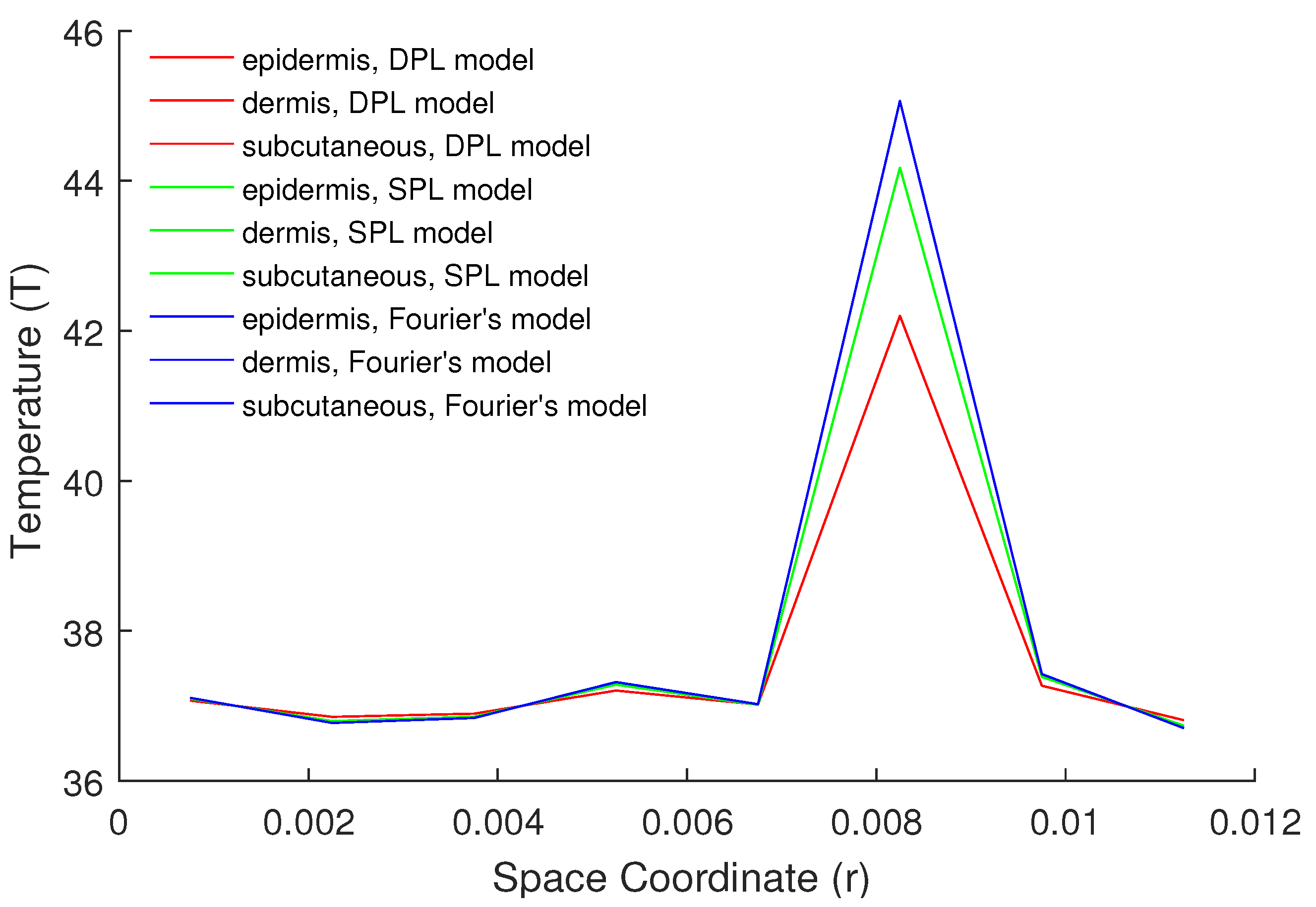
The temperature distributions for boundary conditions of the first, second, and third kinds in multilayer skin tissue are shown in Figure 2. It is quite evident from Figure 2 that the tissue temperature at the tumor site for the first kind of boundary condition is 45 C, whereas for the second and third kind of boundary conditions, it decreases to 42.9 C and 42 C, respectively. Thus, we can say that the temperature distribution at the tumor location during hyperthermia treatment is also affected by the boundary conditions. A comparison for different bioheat models such as Penne’s, SPL, and DPL models under boundary conditions of the first kind is depicted in Figure 3. The difference in temperature distribution among all the three models is near about 0.5 C, which is of great importance in the hyperthermia treatment (see Figure 3). Moreover, the temperature distributions for different values of tissue wall temperature θ w in skin tissue are plotted in Figure 4. We can infer from Figure 4 that the temperature of the skin tissue increases with the increase in θ w at the site of a tumor, while in the epidermis layer, the temperature does not show any change with respect to the values of θ w , which indicates that the surface temperature plays an important role in hyperthermia treatment.
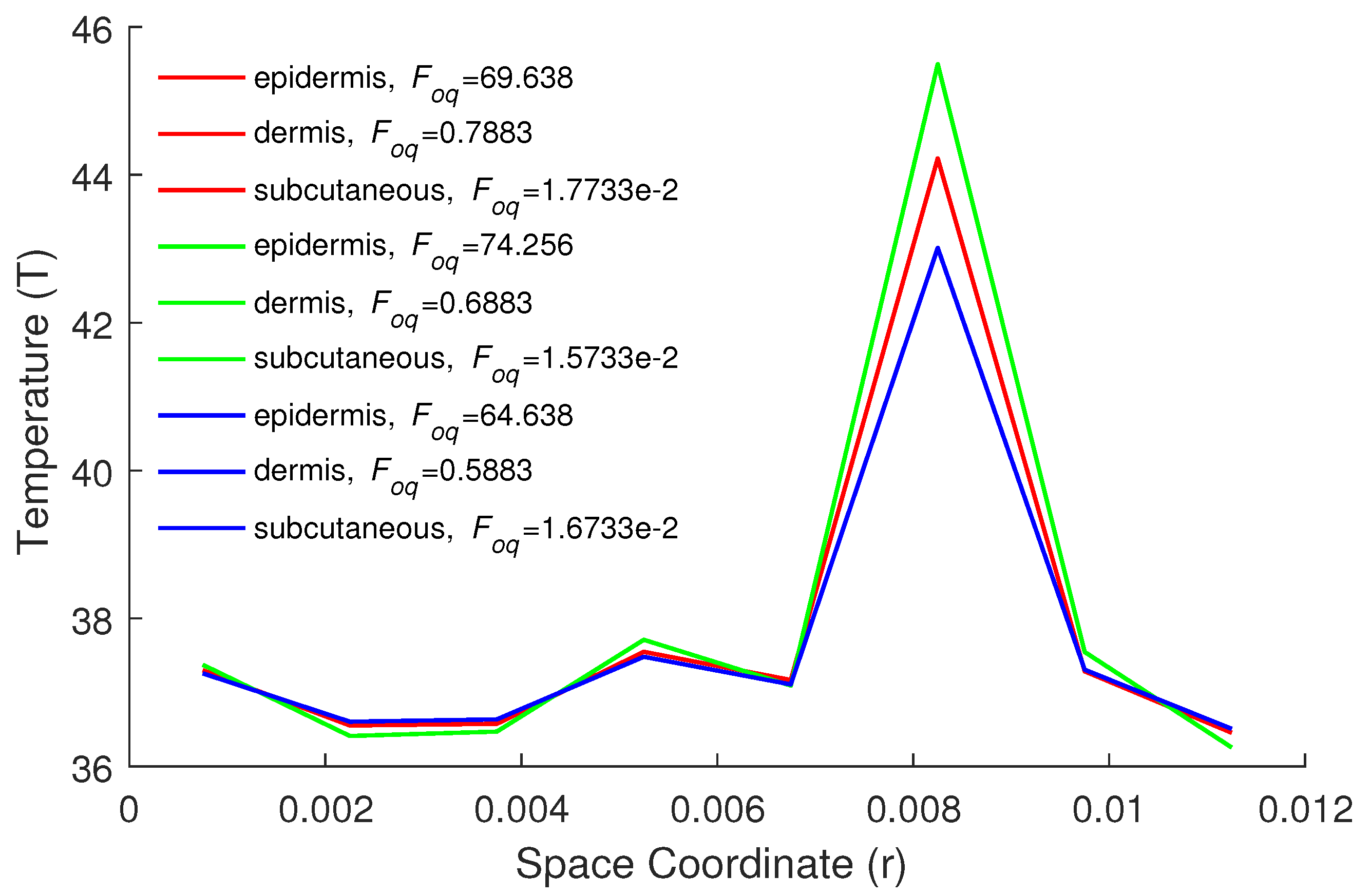
Keeping in view that the values of relaxation time τ q (phase-lag due to heat flux) and τ t (phase-lag due to temperature gradient) are both significant in the DPL model during the treatment process, we have plotted the temperature profiles for various values of τ q and τ t in skin tissue in Figure 5 and Figure 6. From Figure 5, a decrease in temperature distribution is observed at the tumor site for both the dermis and subcutaneous layers with an increase in the relaxation time τ t and keeping τ q fixed. Hence, we conclude that the temperature predicted by the SPL bioheat transfer model will always be greater than that of the DPL bioheat transfer model. Likewise, from Figure 6, we demonstrate that the temperature profiles at the area of the tumor increase as the values of relaxation time τ t decrease by taking the fixed value of τ q . Subsequently, from these figures, we infer that the role of thermal relaxation time due to heat flux and temperature gradient is of great importance for an effective treatment.
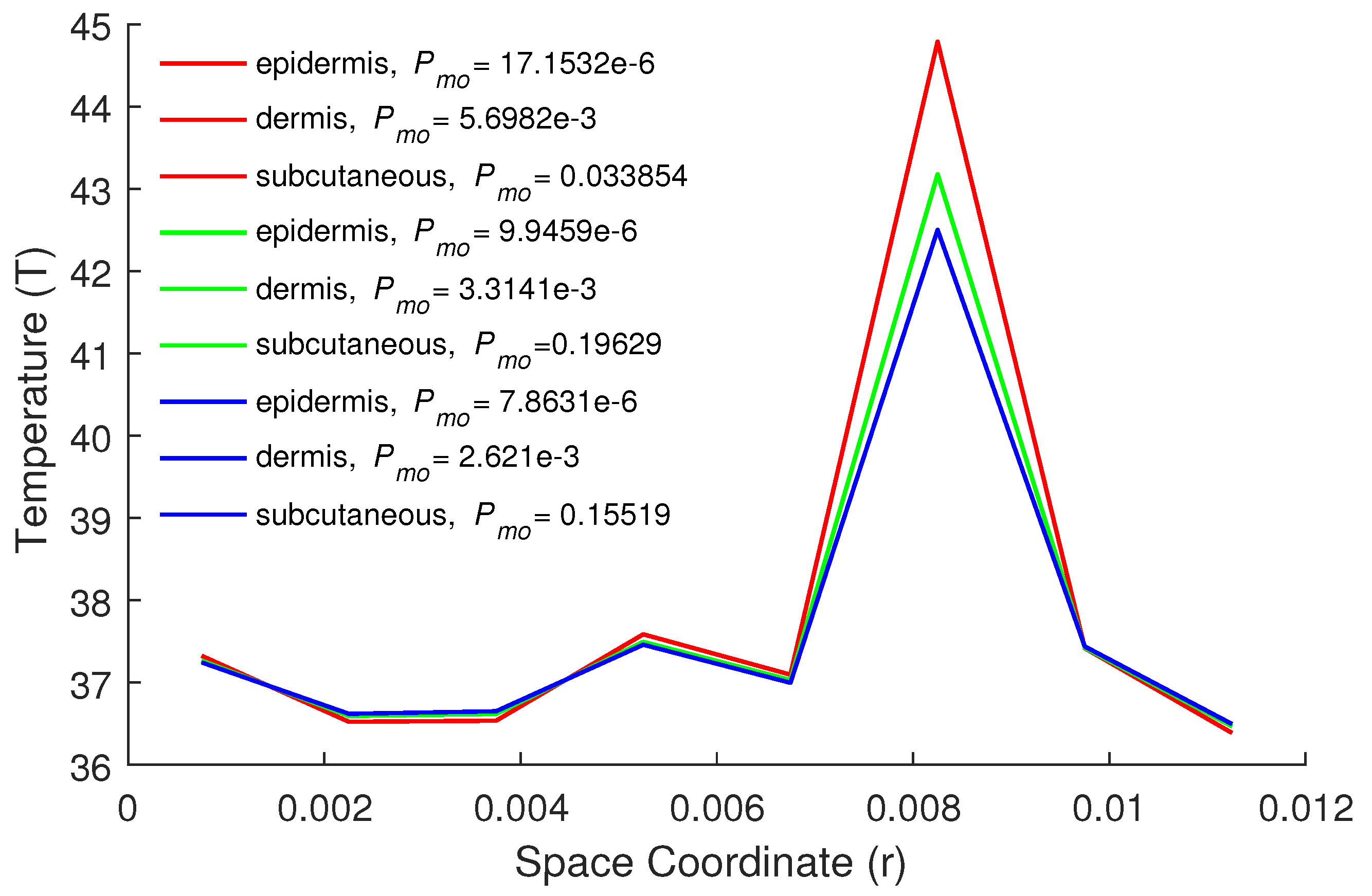
The effect of blood perfusion on multilayer skin tissue under the boundary conditions of the first kind is depicted in Figure 7. It is evident from Figure 7 that as the values of w b increase, the temperature distribution at the site of the tumor decreases, mainly due to the heat loss caused by blood flow. However, by taking the value of blood perfusion equal to zero, the temperature at the site of the tumor increases by 0.65 C, which is also effective for precise prediction of the temperature profile during hyperthermia treatment. In Figure 8, the effect of metabolic heat generation P m o on multilayer skin tissue is shown. From this figure, we infer that the temperature profile at the site of the tumor increases with the increase in the metabolic heat source in the tissue. Moreover, the influence of the metabolic heat term on temperature profiles is quite visible in the dermis and subcutaneous layers in comparison to the epidermis layer.
The temperature profiles in skin tissue for the effect of heat loss due to water diffusion Q d o are described in Figure 9. It is worth noticing that if we kept Q d o = 0 in the dermis layer, the temperature distribution at the site of the tumor remains small, which is extraordinary for the subcutaneous layer at Q d o = 0 due to the fact that the thickness of the subcutaneous layer is more prominent than that of the dermis layer.
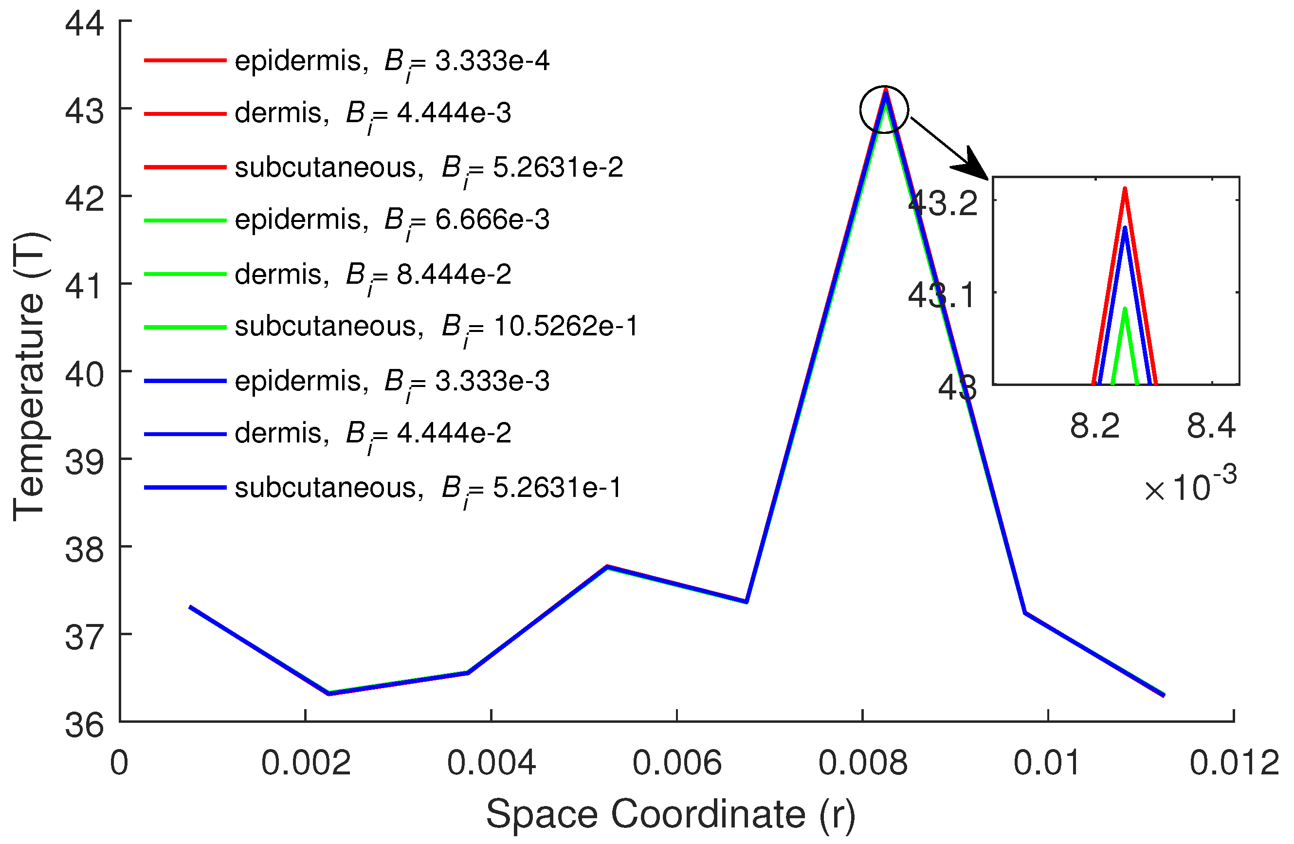
Finally, the impacts of K i and B i on the temperature profiles in skin tissue under boundary conditions of the second and third kinds are presented in Figure 10 and Figure 11. It is quite evident from these figures that the temperature distribution at the site of the tumor increases as the values of heat flux q w increase in skin tissue under the influence of boundary conditions of the second kind, while it does not show much fluctuation under the boundary condition of the third kind with the increase in the values of the heat transfer coefficient h.

6. Conclusions

In this study, the DPL models of bioheat transfer in multilayer skin tissues during hyperthermia treatment under generalized boundary conditions are studied by introducing an efficient wavelet method based on nonorthogonal Fibonacci wavelets. The facilitation has been carried out by constructing the Fibonacci wavelets and the corresponding operational matrices of integration along with a finite element scheme. The effect of different parameters such as tissue wall temperature, time-lag due to heat flux and temperature gradient, blood perfusion, metabolic heat generation, heat loss due to diffusion of water, and boundary conditions of different types on multilayer skin tissues during hyperthermia treatment has been studied and discussed in detail. Nevertheless, it has been observed that the DPL models of bioheat transfer show a lower temperature profile at the site of a tumor in comparison to the SPL and Fourier models. Thus, we conclude that these models give us a more precise prediction of temperature distribution at the tumor site. Finally, it is hoped that the proposed wavelet method can be employed for solving a wide range of physical and biological problems.

Author Contributions

Conceptualization, F.A.S. and M.I.; methodology, H.M.S.; software, M.I.; validation, F.A.S. and M.I.; investigation, F.A.S. and H.M.S.; writing—original draft preparation, H.M.S. and F.A.S.; writing—review and editing, M.I.; supervision, F.A.S. All authors have read and agreed to the published version of the manuscript.

Funding

This research received no external funding.

Institutional Review Board Statement

Not applicable.

Informed Consent Statement

Not applicable.

Conflicts of Interest

The authors declare that they have no conflict of interest.

Abbreviations

The following abbreviations are used in this manuscript:
TTemperature ( C)
T b Arterial blood temperature ( C)
T w Tissue wall temperature ( C)
tTime (s)
rSpace coordinate (m)
TTemperature ( C)
T b Arterial blood temperature ( C)
T w Tissue wall temperature ( C)
tTime (s)
rSpace coordinate (m)
r * Tumor position
c p Specific heat of tissue (J kg 1   C 1 )
LLength of tissue (m)
w b Mass flow rate of blood (kg m 3 s 1 )
D f Water diffusion in tissue (m 2 s 1 )
M w Molar mass of water (g mol 1 )
P w Vapor pressure of water (Pa)
R a Universal gas constant (J mol 1 )
RHRelative humidity (%)
ρ Tissue density (kg m 3 )
kThermal conductivity of tissue (Wm 1 C 1 )
c p b Specific heat of blood (J kg 1 C 1 )
τ q Phase lag of heat flux (s)
τ t Phase lag of temperature gradient (s)
Q m Heat generation due to metabolism in the skin tissue (Wm 3 )
Q d Heat loss due to water diffusion in the tissue (Wm 3 )
Q v Heat loss due to water vaporization in the tissue (Wm 3 )
Q r External heat source (Wm 3 )
SAntenna constant (m 1 )
PAntenna power (W)
Δ mWater vaporization rate of skin surface (g m 2 s 1 )
Δ H v a p Enthalpy of water vaporization (J kg 1 )
δ cAverage distance of momentum boundary layer (m)
Dimensionless variables
ζ Space coordinate
η Fourier number or time
F o q Phase-lag due to heat flux
F o t Phase-lag due to temperature grad.
θ Local tissue temperature
θ b Arterial blood temperature
θ w Tissue wall temperature
P f Blood perfusion coefficient
P r External heat source coefficient
P m o Metabolic heat source coefficient
K i Kirchhoff number
B i Biot number
ζ * Location of tumor

References

  1. Blecher, E.; Chaney-Graves, K.; DeSantis, C.; Edwards, B.; Ferlay, J.; Forman, D.; Grey, N.; Harford, J.; Kramer, J.; McMikel, A. Global Cancer Facts and Figures; American Cancer Society: Atlanta, GA, USA, 2011. [Google Scholar]
  2. Dewhirst, M.W.; Samulski, T.V. Hyperthermia in the Treatment for Cancer; Upjohn: Kalamazoo, MI, USA, 1988. [Google Scholar]
  3. Xu, F.; Lu, T.-J.; Seffen, K.A. Bio-thermomechanics of skin tissues. J. Mech. Phys. Solids. 2008, 56, 1852–1884. [Google Scholar] [CrossRef]
  4. Espinosa, S.; Asproulis, N.; Drikakis, D. Chemotherapy efficiency increase via shock wave interaction with biological membranes: A molecular dynamics study. Microfluid Nanofluid 2014, 16, 613–622. [Google Scholar] [CrossRef]
  5. Romano, M.R.; Romano, V.; Mauro, A.; Angi, M.; Costagliola, C.; Ambrosone, L. The effect of temperature changes in vitreoretinal surgery. Transl. Vis. Sci. Technol. 2016, 5, 4. [Google Scholar] [CrossRef] [Green Version]
  6. Wulff, W. The energy conservation equation for living tissues. IEEE Trans. Biomed. Eng. 1974, 21, 494–495. [Google Scholar] [CrossRef]
  7. Klinger, H.G. Heat transfer in perfused biological tissue. I. Bull. Math. Biol. 1974, 36, 403–415. [Google Scholar]
  8. Gao, F.; Yang, X.-J.; Srivastava, H.M. Exact travelling-wave solutions for linear and non-linear heat transfer equations. Thermal Sci. 2017, 21, 2307–2311. [Google Scholar] [CrossRef]
  9. Chen, M.-M.; Holmes, M.M. Microvascular contributions in tissue heat transfer. Ann. N. Y. Acad. Sci. 1980, 335, 137–150. [Google Scholar] [CrossRef]
  10. Weinbaum, S.; Jiji, L.M.; Lemons, D.E. Theory and experiment for the effect of vascular microstructure on surface tissue heat transfer. I. ASME J. Biomech. Eng. 1984, 106, 321–330. [Google Scholar] [CrossRef]
  11. Nakayama, F.; Kuwahar. A general bioheat transfer model based on the theory of porous media. Int. J. Heat Mass Transf. 2008, 51, 3190–3199. [Google Scholar] [CrossRef] [Green Version]
  12. Pennes, H.H. Analysis of tissue and arterial blood temperature in the resting forearm. J. Appl. Physiol. 1948, 1, 93–122. [Google Scholar] [CrossRef]
  13. Cattaneo, C. A form of heat conduction equation which eliminates the paradox of instantaneous propagation. C. R. Acad. Sci. Paris. 1958, 247, 431–433. [Google Scholar]
  14. Vernotte, P. Les paradoxes de la théorie continue de I équation de l a chleur. C. R. Acad. Sci. Paris 1958, 246, 3154–3155. [Google Scholar]
  15. Tzou, D.Y. Macro-to Micro-Scale Heat Transfer: The Lagging Behavior; Taylor & Francis: Washington, DC, USA, 1996. [Google Scholar]
  16. Zhou, J.; Chen, J.-K.; Zhang, Y. Dual-phase lag effects on thermal damage to biological tissues caused by laser irradiation. Comput. Biol. Med. 2009, 39, 286–293. [Google Scholar] [CrossRef]
  17. Kumar, D.; Singh, J.; Rai, K.N. Analysis of classical Fourier, SPL and DPL heat transfer model in biological tissues in presence of metabolic and external heat source. Heat Mass Transf. 2016, 52, 1089–1107. [Google Scholar] [CrossRef]
  18. Mohamed, A.F. Boundary element algorithm for modeling and simulation of dual phase lag bioheat transfer and biomechanics of anisotropic soft tissues. Int. J. Appl. Mech. 2018, 10, 1850108. [Google Scholar]
  19. Gupta, P.K.; Singh, J.; Rai, K.N.; Rai, S.K. Solution of the heat transfer problem in tissues during hyperthermia by finite difference-decomposition method. Appl. Math. Comput. 2013, 219, 6882–6892. [Google Scholar] [CrossRef]
  20. Noroozi, M.; Saedodin, S.; Ganji, D. A new solution for nonlinear dual phase lagging heat conduction problem. Alex. Eng. J. 2016, 55, 1745–1752. [Google Scholar] [CrossRef] [Green Version]
  21. Mohamed, A.F. Shape design sensitivity and optimization of anisotropic functionally graded smart structures using bicubic B-splines DRBEM. Eng. Anal. Bound. Elem. 2018, 87, 27–35. [Google Scholar]
  22. Lepik, U.; Hein, H. Haar Wavelets with Applications; Springer: New York, NY, USA, 2014. [Google Scholar]
  23. Debnath, L.; Shah, F.A. Wavelet Transforms and Their Applications; Birkhäuser: New York, NY, USA, 2015. [Google Scholar]
  24. Sabermahani, S.; Ordokhani, Y.; Yousefi, S.A. Fibonacci wavelets and their applications for solving two classes of time-varying delay problems. Optim. Control Appl. Meth. 2020, 41, 395–416. [Google Scholar] [CrossRef]
  25. Sabermahani, S.; Ordokhani, Y. Fibonacci wavelets and Galerkin method to investigate fractional optimal control problems with bibliometric analysis. J. Vib. Control 2020, 26, 1–15. [Google Scholar] [CrossRef]
  26. Falcon, S.; Plaza, A. On k-Fibonacci sequences and polynomials and their derivatives. Chaos Solitons Fractals 2009, 39, 1005–1019. [Google Scholar] [CrossRef]
  27. Chen, C.-F.; Hsiao, C.-H. Haar wavelet method for solving lumped and distributed-parameter systems. IEE Proc. Control Theory Appl. 1997, 144, 87–94. [Google Scholar] [CrossRef] [Green Version]
  28. Shah, F.A.; Awana, M.I. A computational wavelet method for solving dual-phase-lag model of bioheat transfer during hyperthermia treatment. Comp. Math. Methods 2020, 2, e1095. [Google Scholar] [CrossRef] [Green Version]
  29. Kumari, T.; Kumar, D.; Rai, K.N.; Singh, S.K. Numerical solution of DPL heat transfer model in multi-layer biological skin tissue of the living body during hyperthermia treatment. Mech. Based Des. Struct. Mach. 2020. [Google Scholar] [CrossRef]
  30. Ming, F.; Weng, W.; Yuan, H. Numerical simulation of the effects of blood perfusion, water diffusion, and vaporization on the skin temperature and burn injuries. Numer. Heat Transf. Part A 2014, 65, 1187–1203. [Google Scholar]
  31. Liu, K.-C. Nonlinear behavior of thermal lagging in concentric living tissues with Gaussian distribution source. Int. J. Heat Mass Transf. 2011, 54, 13–14. [Google Scholar] [CrossRef]
  32. Kumar, P.; Kumar, D.; Rai, K.N. A numerical study on dual-phase-lag model of bio-heat transfer during hyperthermia treatment. J. Therm. Biol. 2015, 49, 98–105. [Google Scholar] [CrossRef]
  33. Scheid, F. Schaum’s Outline of Theory and Problems in Numerical Analysis; McGraW-Hill: New York, NY, USA, 1989. [Google Scholar]
Figure 1. Multilayer skin tissue model.
Energies 14 02254 g001
Figure 2. Temperature distributions for various kinds of boundary conditions.
Energies 14 02254 g002
Figure 3. Comparison of three bioheat models in first kind B.C.
Energies 14 02254 g003
Figure 4. Temperature distributions for different values of θ w in first kind B.C.
Energies 14 02254 g004
Figure 5. Temperature distributions for different values of F o q and F o t = 1.741 × 10 2 , 0.05631, and 1.267 × 10 2 .
Energies 14 02254 g005
Figure 6. Temperature distributions for different values of F o t and F o q = 69.638, 0.7883, and 1.773 × 10 2 .
Energies 14 02254 g006
Figure 7. Temperature distributions for different values of P f in first kind B.C.
Energies 14 02254 g007
Figure 8. Temperature distributions for different values of P m o in first kind B.C.
Energies 14 02254 g008
Figure 9. Temperature distributions for different values of Q d o in first kind B.C.
Energies 14 02254 g009
Figure 10. Temperature distributions for different values of K i in second kind B.C.
Energies 14 02254 g010
Figure 11. Temperature distributions for different values of B i in third kind B.C.
Energies 14 02254 g011
Table 1. Some parameters of multilayer skin tissue used in this paper [30].
ParametersEpidermisDermisSubcutaneous
Thickness (m)0.000080.0020.01
Blood perfusion rate (kg m 3 s 1 )00.001250.00125
Thermal conductivity (W m 1 C 1 )0.240.450.19
Specific heat (J kg 1 C 1 )359033302500
Water diffusivity (m 2 s 1 )5 × 10 10 5 × 10 10 5 × 10 10
Density (kg m 3 )120012001200
Water content (%)707070
Publisher’s Note: MDPI stays neutral with regard to jurisdictional claims in published maps and institutional affiliations.