Article

Digitally Patterned Mesoporous Carbon Nanostructures of Colorless Polyimide for Transparent and Flexible Micro-Supercapacitor

1
Novel Applied Nano Optics Lab., Department of Physics, Kyungpook National University, 80 Daehak-ro, Bukgu, Daegu 41566, Korea
2
Soft Energy Systems and Laser Applications Laboratory, School of Mechanical Engineering, Chung-Ang University, Seoul 06974, Korea
3
Department of Intelligent Energy and Industry, Chung-Ang University, Seoul 06974, Korea
4
Department of Hydrogen and Renewable Energy, Kyungpook National University, 80 Daehak-ro, Bukgu, Daegu 41566, Korea
*
Author to whom correspondence should be addressed.
These authors contributed equally to this work.
Energies 2021, 14(9), 2547; https://doi.org/10.3390/en14092547
Submission received: 31 March 2021 / Revised: 23 April 2021 / Accepted: 26 April 2021 / Published: 29 April 2021
(This article belongs to the Special Issue Novel Materials and Technologies for Supercapacitor Applications)

Abstract

:
Here, we demonstrate the fabrication of a flexible and transparent micro-supercapacitor (MSC), using colorless polyimide (CPI) via a direct laser writing carbonization (DLWC) process. The focused laser beam directly carbonizes the CPI substrate and generates a porous carbon structure on the surface of the CPI substrate. Fluorine, which is one of the chemical compositions of CPI, can enhance the specific area and the conductivity of the carbon electrode by creating micropores in carbon structures during carbonization. Thus, the fabricated carbonized CPI-based MSC shows enhanced specific capacitance (1.20 mF at 10 mV s−1) and better transmittance (44.9%) compared to the conventional PI-based MSC. Additionally, the fabricated carbonized CPI-based MSC shows excellent cyclic performance with minimal reduction (<~10%) in 3000 cycles and high capacitance retention under mechanical bending test conditions. Due to its high flexibility, transparency, and capacitance, we expect that carbonized CPI-based MSC can be further applied to various flexible and transparent applications.

Graphical Abstract

1. Introduction

Recently, the demand for microscaled electronic devices has grown rapidly. Specifically, significant attention has been directed toward transparent and flexible devices in wearable device applications. Thus, this trend has resulted in the active study of small, flexible [1,2] and transparent [3] energy-storage devices. Supercapacitors, featuring a long cycle lifespan and high-power density, are one of the strongest candidates with the potential to replace conventional batteries, which are not usually transparent nor flexible microscale energy devices. Several studies have been conducted on flexible and transparent supercapacitors, using nanomaterials such as silver nanowire and other metal-oxide nanomaterials [4,5]. Pseudocapacitors, usually based on metal oxides [6,7,8] and conductive polymers [9,10], store energy depending on electron charge transfer via electrosorption, redox reactions and intercalation. However, redox reactions can severely damage the surface of the electrode, inducing poor cycle sustainability in pseudocapacitors.
Meanwhile, the electric double-layer capacitor (EDLC), which is another type of supercapacitor, stores energy through electrical adsorption between its conductive electrode and electrolyte ion layer. Since the energy is stored only by the movement of electrolyte ions on the surface without chemical reaction, the surface of the electrode remains undamaged. As a result, EDLCs exhibit robust cycle performance compared to pseudocapacitors. However, the EDLC can only store energy on the surface of the electrode; hence, increasing the specific surface area and porosity of the electrode, which enhances the energy storage performance, is important [11]. Since carbon materials are used to fabricate EDLCs due to their excellent electrical and mechanical properties, such as high conductivity, electrochemical and mechanical stability [12], various carbon materials, such as activated carbon [13], carbon nanotubes [14,15], and onion-like carbon [16], have been studied for increasing the specific area in EDLC.
Besides increasing specific area, doping carbon electrodes with heteroatoms has been actively investigated to enhance the capacitance of supercapacitors [17,18]. For instance, pyrolysis of polymeric precursors, which contains abundant carbon chains with heteroatoms such as nitrogen and oxygen, can produce high-capacitance electrodes due to the remaining heteroatoms [19]. Various organic materials, such as hemp [20], human hair [21], and polyimide [22], can be used as the carbon precursor from which porous carbon materials are derived by high-temperature pyrolysis. However, a high-temperature process usually requires a rigid substrate with good thermal stability and an additional transfer process to fabricate a flexible device.
To overcome these limitations, the direct laser writing carbonization (DLWC) process has been recently suggested for the fabrication of flexible EDLCs. Generally, the DLWC process produces mesoporous carbon nanostructures on the surface of the target substrate by laser irradiation [23,24]. For polyimide substrates, gaseous nitrogen released during the DLWC process [25,26,27,28] induces the formation of a random mesoporous carbon nanostructure, having a high specific surface area [19]. Additionally, the mesoporous carbon nanostructure produced by pyrolysis of polyimide has heteroatoms of nitrogen and oxygen in the surface functional groups [19,26], which can improve capacitance through faradaic redox reactions with acidic electrolytes [29,30]. However, polyimide has poor optical transparency because of its brownish appearance, thus it is difficult to apply polyimide as a transparent supercapacitor. Meanwhile, several studies demonstrated the fabrication of colorless polyimide (CPI)-based flexible supercapacitors using DLWC processes, but the fabricated supercapacitors exhibited poor optical transparency due to the limitation of their relatively wide pattern width [31,32].
In this study, mesoporous carbon electrodes with a small pattern width (~150 μm) were formed on the surface of CPI substrates via a DLWC process. The carbonized CPI substrates were then used to fabricate a flexible and transparent MSC using a carbonized CPI substrate. As shown at Figure S1, CPI contains fluorine atoms that are different from conventional PI. Fluorine is found to increase electrical conductivity of the carbon electrode and enhance the capacitance [29]. During the pyrolysis of the CPI substrate via the DLWC process, the trifluoromethyl (-CF3) contained in CPI is released as fluorine-based gases (CF3, CH2F2, etc.), which produce micropores on the surface of the carbon structure [32]. Therefore, through the application of carbonized CPI produced using the DLWC process, flexible and transparent MSCs, with enhanced capacitance compared to conventional carbonized PI-based MSCs, are fabricated.

2. Experimental Methods

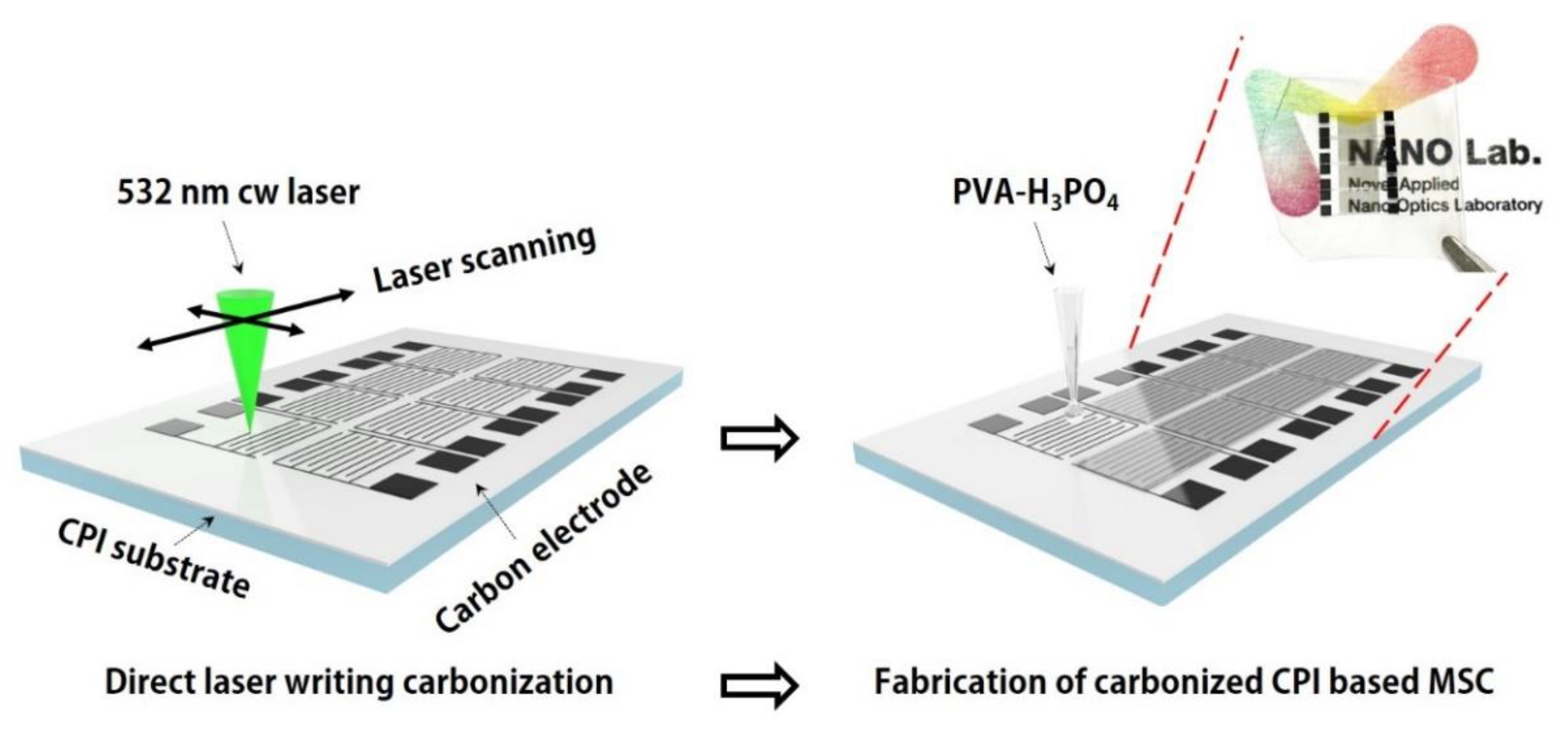
2.1. Preparation of the CPI Substrate and Fabrication of Carbonized CPI-Based MSC

Figure 1 shows a schematic representation of the DLWC process and the fabrication of carbonized CPI-based MSCs by DLWC. The CPI substrate was prepared by the thermal curing of liquid CPI varnish (DFCPI-301, Dongbaek Fine Chem.) To maintain a constant and reproducible film thickness of the CPI substrate, liquid CPI varnish was spread onto a clean glass as a sacrificial substrate by the doctor-blading process. Next, a sequence of thermal curing processes at 80 °C for 30 min, 100 °C for 5 min, 160 °C for 10 min, and 180 °C for 10 min was conducted to produce the CPI substrate, which was 50 μm in thickness. For the fabrication of the carbon electrodes in CPI substrate, a continuous wave laser (Sprout-H-8W, Lighthouse Photonics) of 532 nm in wavelength was used, as shown in Figure 1. Additionally, a two-dimensional (2D) galvano mirror system (hurrySCAN II 14, SCANLAB) combined with the F-theta telecentric lens (4401-461-000-21, LINOS) was used to make the digital pattern of the carbon electrode.
The gel electrolyte was prepared by dissolving polyvinyl alcohol (PVA) and phosphoric acid (H3PO4) in deionized water. First, 4 g PVA was put in 40 mL deionized water with stirring at 100 °C until a clear solution was obtained. Then, 3.2 g H3PO4 was added to the solution and stirred for 1 h at room temperature [15]. For the fabrication of the carbonized CPI-based MSC, the prepared gel electrolyte was coated onto the carbon electrode and solidified overnight at room temperature. As a result, since the gel electrolyte and CPI are transparent, the carbonized CPI-based MSC fabricated by DLWC is flexible and transparent, as shown in the inset image of Figure 1.

2.2. Charaterization

The morphologies of the carbon electrodes were examined using field emission scanning electron microscopy (FE-SEM, Hitach, SU8220) and the chemical properties of the carbon electrodes were characterized by X-ray photoelectron spectroscopy (XPS, ThermoFisher, Waltham, MA, USA, NEXSA) and Raman spectroscopy (Renishaw, Wotton-under-Edge, Groucestershire, UK, inVia reflex). For electrochemical measurements, such as cyclic voltammetry (CV) and galvanostatic charge–discharge (GCD), the carbonized CPI-based MSC was analyzed by an electrochemical workstation (Ivium vertex, Ivium technologies) using a two-electrode system. Electrochemical impedance spectroscopy (EIS, ZIVE SP1, WonATech, Seoul, Korea) was measured at a frequency ranging from 1 Hz to 1 MHz. Transmittance measurement was conducted by UV-VIS spectrophotometer (OPTIZEN™ Alpha, K LAB, Daejeon, Korea) to examine an optical property of the carbonized CPI-based MSC.

3. Results and Discussions

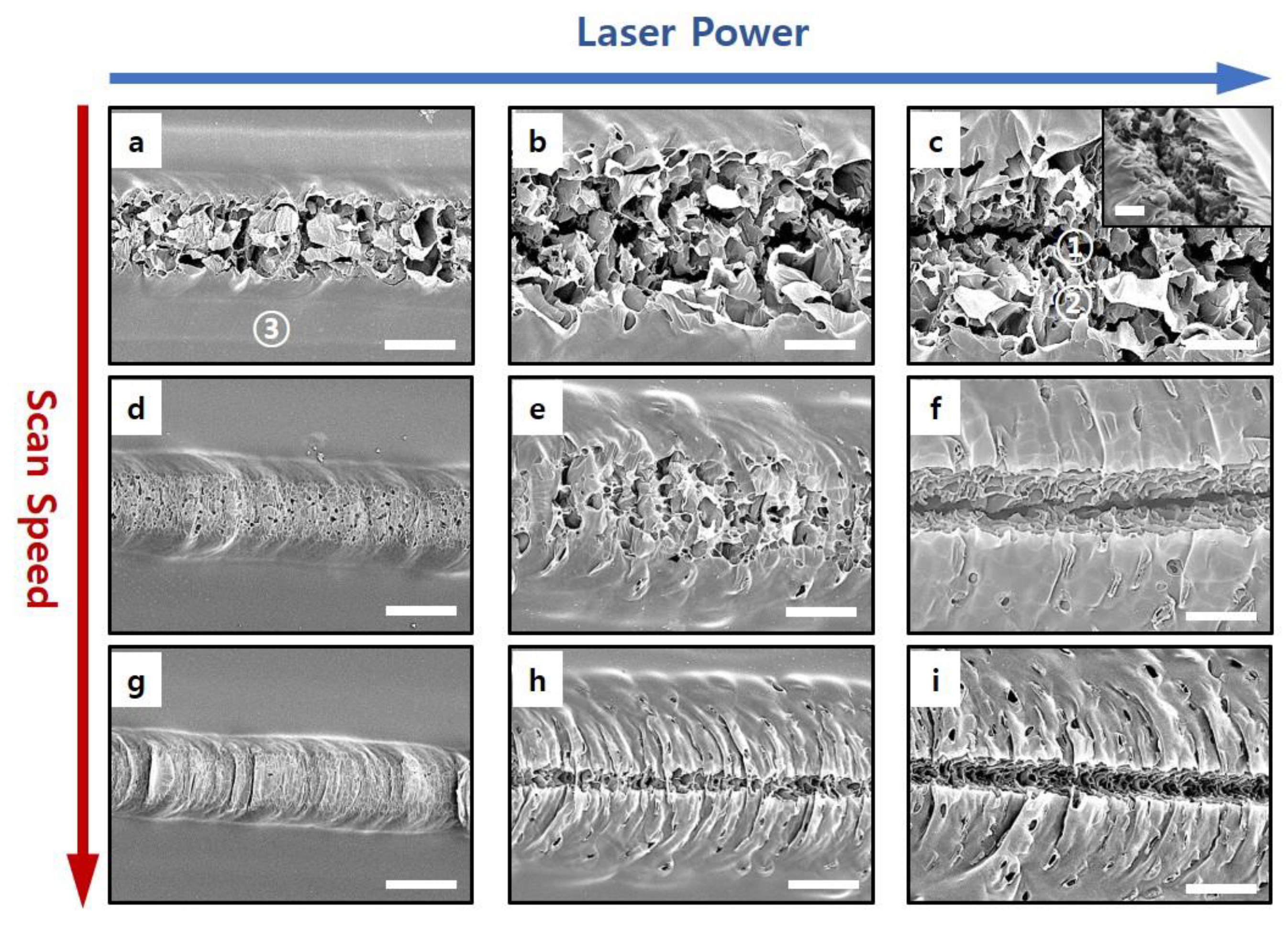
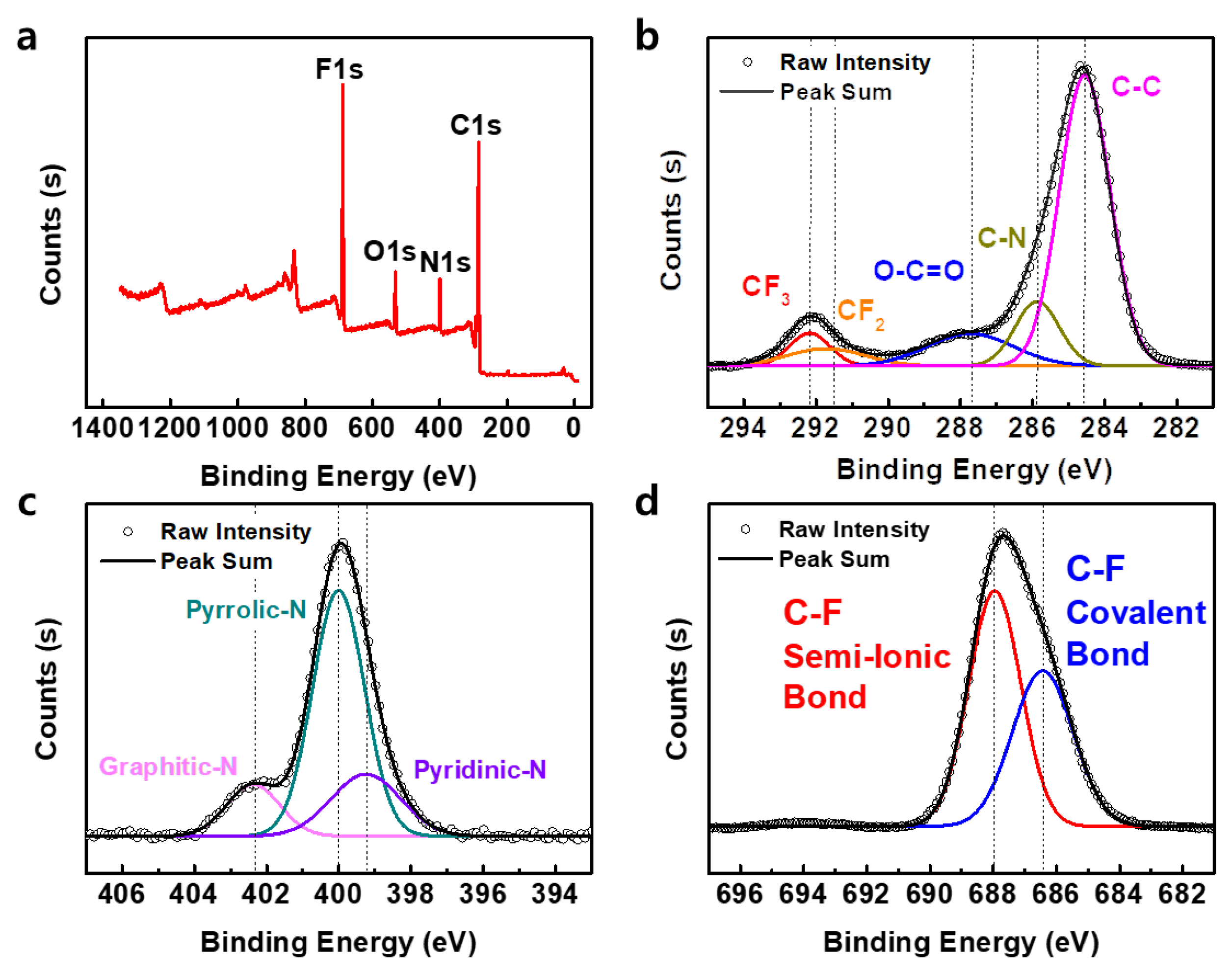
3.1. Laser-Induced Carbonization

Figure 2 shows various SEM images of the carbon electrode made by DLWC with different laser powers and scan speeds. Interestingly, the morphologies of the carbon electrodes are diversely dependent on the laser conditions. At low laser scan speeds (Figure 2a–c), the porosity of the produced carbon widens as the laser power is increased. Meanwhile, at high laser scan speeds (Figure 2g–i), an increase in a narrower and deeper carbon crevice is more dominant rather than an increase in porosity as the laser power is increased. It can be confirmed that the low scan speed and high laser power are suitable conditions for fabricating deep crevices, as well as highly porous carbon nanostructures having high specific surface areas, as shown in Figure 2c and its inset image (tilting SEM image).
Figure 3a shows the Raman spectrum according to the selected areas of the carbon electrode at a laser power and scan speed of 150 mW and 1 mm s−1, respectively (denoted in Figure 2a,c). The measured peaks at 1350, 1580, and 2690 cm−1 correspond to the D, G, and 2D peaks (Carbon D and G bands), respectively. As shown in Figure 3a, the blue-colored spectrum represents the carbon electrode produced by DLWC, which shows strong carbon peaks that are consistent with a previous study on PI substrates fabricated by DLWC [25], whereas the yellow-colored spectrum represents the edge of the produced carbon electrode, which shows mixed peaks of amorphous and graphitic carbon. This observation is also in excellent agreement with a previous study on PI substrates [25].
These results can be explained by the pyrolysis process of PI at a high temperature. During pyrolysis, the PI substrate becomes amorphous carbon, at first. After then, under a relatively high-temperature condition, carbonized polyimide is crystallized. The process is called graphitization [19]. Since the intensity distribution of the applied laser is Gaussian, the induced temperature field on the CPI substrate made by DLWC is also Gaussian. Therefore, as reported in a previous study on the DLWC of PI substrates [33], crystallized carbon nanostructures (laser-induced graphene) are produced at the middle of the carbon electrode and the amorphous-graphitic carbon structure is produced at the edge of the carbon electrode in the CPI substrate.
Figure 3b shows the Raman spectrum of the carbon electrode at different laser powers. The difference between the intensity of D and G peaks increases as the laser power increases. These results imply that the crystallinity of the carbon electrode depends on the applied laser power. With higher laser power, lower surface defects are formed on the produced carbon electrode. Figure S2 shows the Raman spectra of the crystallized and amorphous area in a carbon electrode fabricated by various laser powers. As shown in Figure S2, the crystallized area is widened as the laser power is increased. During DLWC, the laser parameters affect electrical resistance and the pattern width as well as the crystallinity of the carbon electrode. Therefore, as the laser power and scan speed are increased and decreased, respectively, the conductivity of the carbon electrode is improved, whereas the pattern width of the carbon electrode becomes wider, as shown in Figure 3c,d. The line width of the carbon electrode produced by DLWC at 150 mW and 1 mm s−1 is ~150 μm, which is the optimal condition for maximum areal capacitance in this study.
Figure 4a shows the full XPS spectrum of the carbon electrode, confirming the existence of C, F, N, and O. The measured atomic ratios of C, F, N, and O in the XPS spectrum are 65.92%, 19.42%, 7.92%, and 6.74%, respectively. For the DLWC of PI [28], only N and O exist, whereas F, N, and O were found in the carbon electrodes fabricated by the DLWC of the CPI substrate.
For a detailed analysis of the CPI substrate fabricated by DLWC, the measured peaks in the XPS spectra were further examined. The deconvoluted C1s spectra in Figure 4b show dominating C–C (284.6 eV), C–N (285.8 eV), O–C=O (287.7 eV), CF2 (291.7 eV), and CF3 (292.2 eV) bonding peaks. Interestingly, the deconvoluted C1s spectra indicate the new CF2 peak as well as the CF3 peak, which originates from the pristine CPI substrate (see Figure S3b of the Supplementary Materials). In addition, from the two peaks of covalent (686.4 eV) and semi-ionic (686.4 eV) bonds in the F1s spectra of Figure 4c, fluorine existence in the carbon electrode are confirmed. Compared to the carbon electrode fabricated by the DLWC of PI, the presence of fluorine in the carbon electrode fabricated by the DLWC of CPI enhances the electrical conductivity and resistance [29].
Meanwhile, the deconvoluted N1s spectra (Figure 4d) show various nitrogen species and carbon structures, including pyridinic-N (399.2 eV), pyrrolic-N (400 eV), and graphitic-N (402.3 eV). As shown in Figure 5, pyrrolic-N is a pentagon carbon ring in which the nitrogen atom replaces one carbon. In the case of pyridinic-N and graphitic-N, nitrogen is located at the end of the hexagon carbon ring and inside the hexagon carbon ring, respectively. Compared to the pristine CPI substrate (see Figure S3c of the Supplementary Materials), Figure 4d indicates that new pyridinic-N and graphitic-N peaks were generated in the CPI substrate after the DLWC process. Thus, these results confirm that the nitrogen in the pentagon carbon ring and fluorine atoms in CF3 groups might be broken and replaced in the pristine CPI during the DLWC process (Figure 5), which is consistent with previous studies on the conventional pyrolysis of CPI [19,34]. Additionally, since nitrogen-based gases [25,26,27,28] and fluorine-based gases [29,30,32] are released from CPI during the pyrolysis, micropores on the surface of carbon electrode are increased by the DLWC process. As a result, these nitrogen species and mesoporous carbon structures react with electrolytes, which improves the capacitance in a supercapacitor through faradaic redox reactions [29].

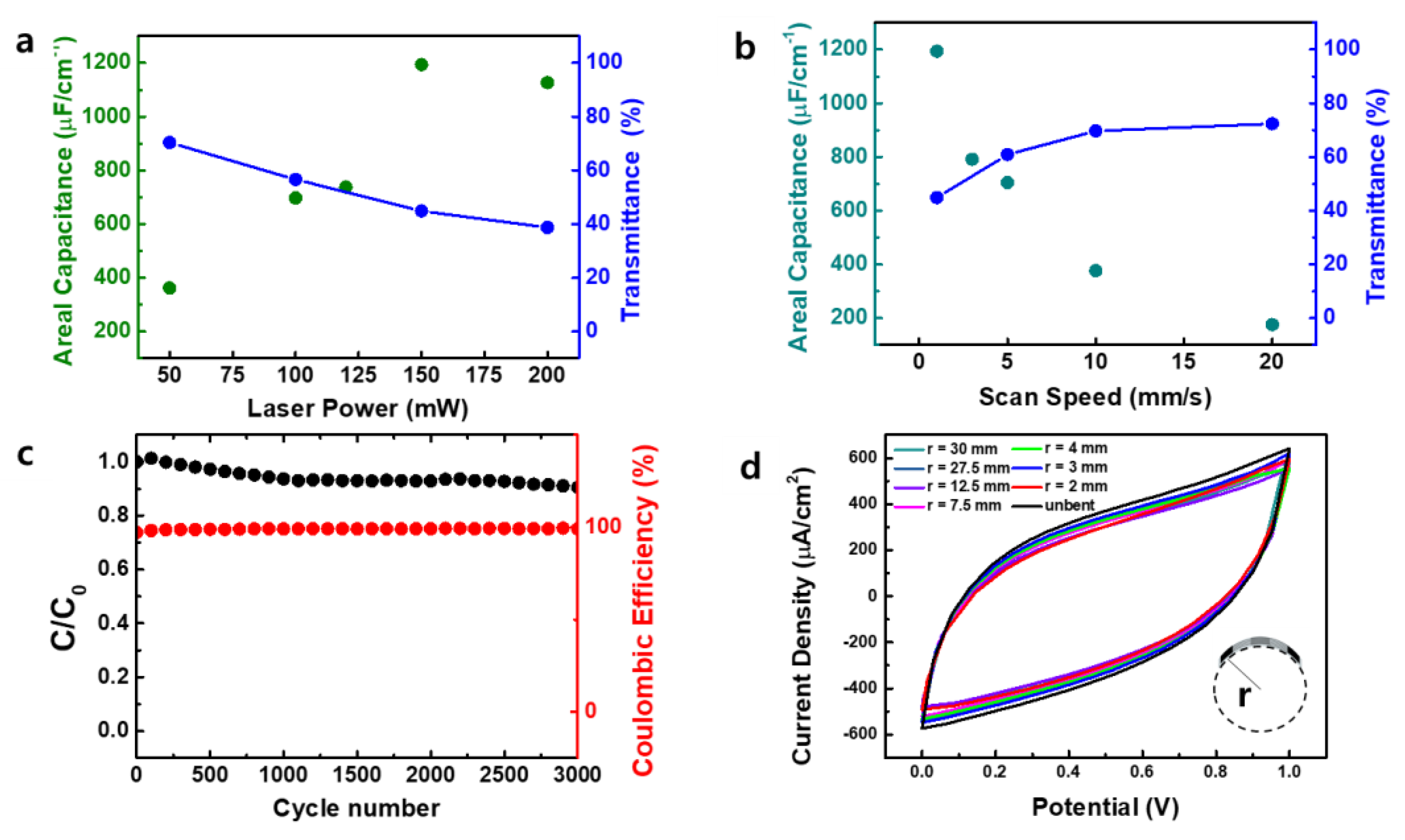
3.2. Electrochemical Characteristics of MSCs

The areal capacitance ( C A ) is calculated as follows [25]:
C A = I   d V 2 A · v · Δ V
where, I   d V , A, v , and Δ V are the area under the CV curve, device area, voltage scan rate, and potential window width, respectively. Using the computed areal capacitance, the electrochemical measurements of carbonized CPI-based MSC were plotted (Figure 6). Figure 6a shows CV curves in the potential range of 0–1 V at various scan rates from 10 mV s−1 to 1V s−1. Since the nitrogen and oxygen heteroatoms in the carbon electrode cause the faradaic redox reactions leading to a pseudocapacitive effect [19,29,30], the CV curve shows a quasi-rectangular shape in previously reported MSC based on carbonized PI by DLWC [26,35], against the ideal rectangular shape of typical EDLCs [36]. Similar to results of previously reported MSC based on carbonized PI, the EDLC characteristic is dominant but faradaic redox reactions from nitrogen and oxygen heteroatoms in the carbon electrode also contribute to the specific capacitance in MSC based on carbonized CPI.
Figure 6b shows the areal capacitance of the carbonized CPI-based MSC at different scan rates. A maximum areal capacitance of 1.20 mF cm−2 at 10 mV s−1 was recorded, which is a higher value that that reported in a previous study of carbonized PI-based MSC [26]. As aforementioned, since the fluorine in the CPI substrate generates highly electronegative fluorine functional groups in the surface of the carbon electrode, the carbonized CPI-based MSC shows enhanced capacitance and electroconductivity [29,37] Additionally, through the decomposition of CF3 during DLWC, fluorinated gases are released, leading to induced micropores on the carbon structure, which increases the specific area [34].
GCD curves are obtained at current densities from 0.1 to 1 mA cm−2 for carbonized CPI based MSC (Figure 6c). The measured GCD curves exhibit nearly linear shapes, which is generally found from typical EDLCs [38,39]. This suggests that the non-faradaic charge storage mechanism prevails in the charge–discharge process.
Figure 6d shows the nyquist plot of CPI-based MSC. In the plot, the equivalent series resistance (ESR) estimated from the intercept of the real axis is ~238 Ω. At low frequencies, the slope of the measured plot is semi-vertical. In addition, at high frequencies, the curve of the measured plot is observed as slightly horizontal, as shown in the inset image of Figure 6d. Since ion transportation is delayed at high frequencies due to the drastic change in the electric field, the electrode can only accommodate a few ions existing in the limited area, thus the capacitance and apparent pore resistance are decreased. These results are consistent with typical EDLC [40], but also with previously reported MSC based on carbonized PI [26].
Figure 7a,b shows the areal capacitance at a scan rate of 10 mV s−1 and the transmittance at different laser parameters. The measured areal capacitance of the carbonized CPI-based MSC increases as the laser power and scan speed increase and decrease, respectively. A maximum areal capacitance of 1.2 mF cm−2 at 150 mW and 1 mm s−1 was recorded. As shown in the SEM images of carbon electrodes at Figure 2, the specific area also expands as the laser power and scan speed increase and decrease, respectively. Thus, it confirmed that higher laser power contributes a higher specific area of carbon electrode and enhances capacitive performance. In Figure 7a, however, the highest laser power condition (200 mW) makes a areal capacitance lower than 150 mW. As shown in Figure S4, since the carbon electrode produced by DLWC at 200 mW and 1 mm s−1 can be exploded and destroyed during DLWC, the specific capacitance might be decreased under excess laser power conditions. Meanwhile, the higher laser power makes a wider carbon electrode (Figure 3c). Thus, the transmittance of the carbonized CPI based MSC is decreased from ~70% to ~44% as there is an increase in laser power at 550 nm wavelength, as shown in Figure 7a. This is reason why the transmittance of the carbonized CPI-based MSC decreases as the areal capacitance is increased. A detailed plot about the transmittance of the carbonized CPI-based MSC is provided in Supplementary Materials (Figure S5). Therefore, the highest areal capacitance of 1.2 mF cm−2 shows transmittance of 44.9% at 150 mW and 1 mm s−1.
The long cycle stability of the carbonized CPI-based MSC for capacitance retention and Coulombic efficiency was conducted through a 3000-cyclic charge–discharge test at a current density of 0.3 mA cm−2 (Figure 7c). Capacitance retention of ~90% of the initial value after the 3000-cyclic test was recorded, indicating good cycle stability. Additionally, the Coulombic efficiency maintains almost 99% of the initial cycle during 3000 cycles. Thus, these results confirm that the carbonized CPI-based MSC has high charge—discharge energy efficiency.
For the flexibility test of the carbonized CPI-based MSC, the CV measurements were conducted with different radii of the carbonized CPI-based MSC, which were attached around cylinders with various radii from 30 mm to 2 mm. Figure 7d shows the measured CV of the carbonized CPI-based MSC under mechanical bending at a scan rate of 100 mV s−1. Since the measured CV results show minimal variation in all bending configurations, the carbonized CPI-based MSC is confirmed to have good flexibility. Therefore, transparent and flexible carbonized CPI-based MSCs can be fabricated by DLWC.

4. Conclusions

In summary, we introduced the fabrication of flexible and transparent carbonized CPI-based MSCs by DLWC. Due to the presence of fluorine in the CPI substrate, the carbonized CPI-based MSC shows enhanced electroconductivity. By creating micropores in the carbon electrodes during laser carbonization, the specific area of the carbonized CPI-based MSC increased, resulting in better capacitance performance compared to conventional PI-based MSC. The fabricated carbonized CPI-based MSC shows stable cycle performance and good mechanical robustness. Thus, due to its mechanical flexibility and transparency, the carbonized CPI-based MSC can be applied to other flexible and transparent optoelectronic devices, including MSCs.

Supplementary Materials

The following are available online at https://www.mdpi.com/article/10.3390/en14092547/s1, Figure S1: Chemical structure of PI and CPI. Figure S2: Raman spectra of carbon electrode fabricated by laser. Figure S3: The XPS survey spectrum of pristine CPI substrate and core level deconvoluted spectra. Figure S4: The SEM image of carbon electrode produced by DLWC at 200 mW and 1 mm s−1. Figure S5: Digital images and the transmittances of carbonized CPI based MSC with different laser powers.

Author Contributions

Conceptualization, H.K. and J.Y.; methodology, H.K. and S.H.; validation, H.K. and T.H.; formal analysis, H.K., J.B.I. and J.Y.; investigation, H.K. and S.H.; writing—original draft preparation, H.K., S.H., J.B.I. and J.Y.; writing—review and editing, H.K., S.H., T.H., J.B.I. and J.Y.; supervision, J.Y.; funding acquisition, J.Y. All authors have read and agreed to the published version of the manuscript.

Funding

Not applicable.

Institutional Review Board Statement

Not applicable.

Informed Consent Statement

Not applicable.

Data Availability Statement

Not applicable.

Acknowledgments

This work was supported through a National Research Foundation of Korea (NRF) grant funded by the Korean government (NRF-2019R1A2C1090510, NRF-2018R1A6A1A06024970).

Conflicts of Interest

The authors declare no conflict of interest.

References

  1. Ko, Y.; Kwon, M.; Bae, W.K.; Lee, B.; Lee, S.W.; Cho, J. Flexible supercapacitor electrodes based on real metal-like cellulose papers. Nat. Commun. 2017, 8, 1–11. [Google Scholar] [CrossRef] [PubMed] [Green Version]
  2. Shao, Y.; Li, J.; Li, Y.; Wang, H.; Zhang, Q.; Kaner, R.B. Flexible quasi-solid-state planar micro-supercapacitor based on cellular graphene films. Mater. Horizons 2017, 4, 1145–1150. [Google Scholar] [CrossRef]
  3. Cheng, T.; Zhang, Y.-Z.; Yi, J.-P.; Yang, L.; Zhang, J.-D.; Lai, W.-Y.; Huang, W. Inkjet-printed flexible, transparent and aesthetic energy storage devices based on PEDOT:PSS/Ag grid electrodes. J. Mater. Chem. A 2016, 4, 13754–13763. [Google Scholar] [CrossRef]
  4. Lee, H.; Hong, S.; Lee, J.; Suh, Y.D.; Kwon, J.; Moon, H.; Kim, H.; Yeo, J.; Ko, S.H. Highly Stretchable and Transparent Supercapacitor by Ag–Au Core–Shell Nanowire Network with High Electrochemical Stability. ACS Appl. Mater. Interfaces 2016, 8, 15449–15458. [Google Scholar] [CrossRef] [PubMed]
  5. Moon, H.; Lee, H.; Kwon, J.; Suh, Y.D.; Kim, D.K.; Ha, I.; Yeo, J.; Hong, S.; Ko, S.H. Ag/Au/Polypyrrole Core-shell Nanowire Network for Transparent, Stretchable and Flexible Supercapacitor in Wearable Energy Devices. Sci. Rep. 2017, 7, 41981. [Google Scholar] [CrossRef] [Green Version]
  6. Jung, J.; Kim, H. W18O49 nanowires assembled on carbon felt for application to supercapacitors. Appl. Surf. Sci. 2018, 433, 750–755. [Google Scholar] [CrossRef]
  7. Shinde, P.A.; Lokhande, A.C.; Patil, A.M.; Lokhande, C.D. Facile synthesis of self-assembled WO3 nanorods for high-performance electrochemical capacitor. J. Alloys Compd. 2019, 770, 1130–1137. [Google Scholar] [CrossRef]
  8. Hwang, S.; Hwang, T.; Kong, H.; Lee, S.; Yeo, J. Novel fabrication method of hierarchical planar micro-supercapacitor via laser-induced localized growth of manganese dioxide nanowire arrays. Appl. Surf. Sci. 2021, 552, 149382. [Google Scholar] [CrossRef]
  9. Acharya, S.; Santino, L.M.; Lu, Y.; Anandarajah, H.; Wayne, A.; D’Arcy, J.M. Ultrahigh stability of high-power nanofibrillar PEDOT supercapacitors. Sustain. Energy Fuels 2017, 1, 482–491. [Google Scholar] [CrossRef]
  10. Bryan, A.M.; Santino, L.M.; Lu, Y.; Acharya, S.; D’Arcy, J.M. Conducting Polymers for Pseudocapacitive Energy Storage. Chem. Mater. 2016, 28, 5989–5998. [Google Scholar] [CrossRef]
  11. Kondrat, S.; Pérez, C.R.; Presser, V.; Gogotsi, Y.; Kornyshev, A.A. Effect of pore size and its dispersity on the energy storage in nanoporous supercapacitors. Energy Environ. Sci. 2012, 5, 6474–6479. [Google Scholar] [CrossRef]
  12. Zhang, L.L.; Zhou, R.; Zhao, X.S. Graphene-based materials as supercapacitor electrodes. J. Mater. Chem. 2010, 20, 5983–5992. [Google Scholar] [CrossRef]
  13. Gamby, J.; Taberna, P.; Simon, P.; Fauvarque, J.; Chesneau, M. Studies and characterisations of various activated carbons used for carbon/carbon supercapacitors. J. Power Source 2001, 101, 109–116. [Google Scholar] [CrossRef]
  14. Hsia, B.; Marschewski, J.; Wang, S.; Bin In, J.; Carraro, C.; Poulikakos, D.; Grigoropoulos, C.P.; Maboudian, R. Highly flexible, all solid-state micro-supercapacitors from vertically aligned carbon nanotubes. Nanotechnology 2014, 25, 055401. [Google Scholar] [CrossRef]
  15. Kaempgen, M.; Chan, C.K.; Ma, J.; Cui, Y.; Gruner, G. Printable Thin Film Supercapacitors Using Single-Walled Carbon Nanotubes. Nano Lett. 2009, 9, 1872–1876. [Google Scholar] [CrossRef] [PubMed]
  16. Pech, D.; Brunet, M.; Durou, H.; Huang, P.; Mochalin, V.; Gogotsi, Y.; Taberna, P.-L.; Simon, P. Ultrahigh-power micrometre-sized supercapacitors based on onion-like carbon. Nat. Nanotechnol. 2010, 5, 651–654. [Google Scholar] [CrossRef] [PubMed]
  17. Ariharan, A.; Viswanathan, B.; Nandhakumar, V. Nitrogen Doped Graphene as Potential Material for Hydrogen Storage. Graphene 2017, 6, 41–60. [Google Scholar] [CrossRef] [Green Version]
  18. Karbhal, I.; Basu, A.; Patrike, A.; Shelke, M.V. Laser patterning of boron carbon nitride electrodes for flexible micro-supercapacitor with remarkable electrochemical stability/capacity. Carbon 2021, 171, 750–757. [Google Scholar] [CrossRef]
  19. Inagaki, M.; Ohta, N.; Hishiyama, Y. Aromatic polyimides as carbon precursors. Carbon 2013, 61, 1–21. [Google Scholar] [CrossRef]
  20. Wang, H.; Xu, Z.; Kohandehghan, A.; Li, Z.; Cui, K.; Tan, X.; Stephenson, T.J.; King’Ondu, C.K.; Holt, C.M.B.; Olsen, B.C.; et al. Interconnected Carbon Nanosheets Derived from Hemp for Ultrafast Supercapacitors with High Energy. ACS Nano 2013, 7, 5131–5141. [Google Scholar] [CrossRef]
  21. Qian, W.; Sun, F.; Xu, Y.; Qiu, L.; Liu, C.; Wang, S.; Yan, F. Human hair-derived carbon flakes for electrochemical supercapacitors. Energy Environ. Sci. 2014, 7, 379–386. [Google Scholar] [CrossRef]
  22. Li, Y.; Dong, J.; Zhang, J.; Zhao, X.; Yu, P.; Jin, L.; Zhang, Q. Nitrogen-Doped Carbon Membrane Derived from Polyimide as Free-Standing Electrodes for Flexible Supercapacitors. Small 2015, 11, 3476–3484. [Google Scholar] [CrossRef]
  23. Dyer, P.; Pervolaraki, M.; Lippert, T. Experimental studies and thermal modelling of 1064- and 532-nm Nd:YVO4 micro-laser ablation of polyimide. Appl. Phys. A 2005, 80, 529–536. [Google Scholar] [CrossRef]
  24. Ruan, X.; Wang, R.; Luo, J.; Yao, Y.; Liu, T. Experimental and modeling study of CO2 laser writing induced polyimide carbonization process. Mater. Des. 2018, 160, 1168–1177. [Google Scholar] [CrossRef]
  25. Lin, J.; Peng, Z.; Liu, Y.; Ruiz-Zepeda, F.; Ye, R.; Samuel, E.L.G.; Yacaman, M.J.; Yakobson, B.I.; Tour, J.M. Laser-induced porous graphene films from commercial polymers. Nat. Commun. 2014, 5, 5714. [Google Scholar] [CrossRef]
  26. Bin In, J.; Hsia, B.; Yoo, J.-H.; Hyun, S.; Carraro, C.; Maboudian, R.; Grigoropoulos, C.P. Facile fabrication of flexible all solid-state micro-supercapacitor by direct laser writing of porous carbon in polyimide. Carbon 2015, 83, 144–151. [Google Scholar] [CrossRef]
  27. Cai, J.; Lv, C.; Watanabe, A. Cost-effective fabrication of high-performance flexible all-solid-state carbon micro-supercapacitors by blue-violet laser direct writing and further surface treatment. J. Mater. Chem. A 2016, 4, 1671–1679. [Google Scholar] [CrossRef]
  28. Wang, S.; Yu, Y.; Li, R.; Feng, G.; Wu, Z.; Compagnini, G.; Gulino, A.; Feng, Z.; Hu, A. High-performance stacked in-plane supercapacitors and supercapacitor array fabricated by femtosecond laser 3D direct writing on polyimide sheets. Electrochim. Acta 2017, 241, 153–161. [Google Scholar] [CrossRef]
  29. Zhou, J.; Lian, J.; Hou, L.; Zhang, J.; Gou, H.; Xia, M.; Zhao, Y.; Strobel, T.A.; Tao, L.; Gao, F. Ultrahigh volumetric capacitance and cyclic stability of fluorine and nitrogen co-doped carbon microspheres. Nat. Commun. 2015, 6, 8503. [Google Scholar] [CrossRef] [PubMed]
  30. Lota, G.; Grzyb, B.; Machnikowska, H.; Machnikowski, J.; Frackowiak, E. Effect of nitrogen in carbon electrode on the supercapacitor performance. Chem. Phys. Lett. 2005, 404, 53–58. [Google Scholar] [CrossRef]
  31. Huang, F.; Feng, G.; Yin, J.; Zhou, S.; Shen, L.; Wang, S.; Luo, Y. Direct Laser Writing of Transparent Polyimide Film for Supercapacitor. Nanomaterials 2020, 10, 2547. [Google Scholar] [CrossRef]
  32. Kim, M.; Gu, M.G.; Jeong, H.; Song, E.; Jeon, J.W.; Huh, K.-M.; Kang, P.; Kim, S.-K.; Kim, B.G. Laser Scribing of Fluorinated Polyimide Films to Generate Microporous Structures for High-Performance Micro-supercapacitor Electrodes. ACS Appl. Energy Mater. 2021, 4, 208–214. [Google Scholar] [CrossRef]
  33. Lippert, T.; Ortelli, E.; Panitz, J.-C.; Raimondi, F.; Wambach, J.; Wei, J.; Wokaun, A. Imaging-XPS/Raman investigation on the carbonization of polyimide after irradiation at 308 nm. Appl. Phys. A 1999, 69, S651–S654. [Google Scholar] [CrossRef]
  34. Ohta, N.; Nishi, Y.; Morishita, T.; Tojo, T.; Inagaki, M. Preparation of microporous carbon films from fluorinated aromatic polyimides. Carbon 2008, 46, 1350–1357. [Google Scholar] [CrossRef]
  35. Hulicova-Jurcakova, D.; Kodama, M.; Shiraishi, S.; Hatori, H.; Zhu, Z.H.; Lu, G.Q. Nitrogen-Enriched Nonporous Carbon Electrodes with Extraordinary Supercapacitance. Adv. Funct. Mater. 2009, 19, 1800–1809. [Google Scholar] [CrossRef]
  36. Costentin, C.; Porter, T.R.; Savéant, J.-M. How Do Pseudocapacitors Store Energy? Theoretical Analysis and Experimental Illustration. ACS Appl. Mater. Interfaces 2017, 9, 8649–8658. [Google Scholar] [CrossRef]
  37. Kim, M.-H.; Yang, J.-H.; Kang, Y.-M.; Park, S.-M.; Han, J.T.; Kim, K.-B.; Roh, K.C. Fluorinated activated carbon with superb kinetics for the supercapacitor application in nonaqueous electrolyte. Colloids Surf. A Physicochem. Eng. Asp. 2014, 443, 535–539. [Google Scholar] [CrossRef]
  38. Lei, C.; Amini, N.; Markoulidis, F.; Wilson, P.; Tennison, S.; Lekakou, C. Activated carbon from phenolic resin with controlled mesoporosity for an electric double-layer capacitor (EDLC). J. Mater. Chem. A 2013, 1, 6037–6042. [Google Scholar] [CrossRef]
  39. Delekta, S.S.; Smith, A.D.; Li, J.; Östling, M. Inkjet printed highly transparent and flexible graphene micro-supercapacitors. Nanoscale 2017, 9, 6998–7005. [Google Scholar] [CrossRef]
  40. Kötz, R.; Carlen, M. Principles and applications of electrochemical capacitors. Electrochimica Acta 2000, 45, 2483–2498. [Google Scholar] [CrossRef]
Figure 1. Schematic illustration of the DLWC process and fabrication of carbonized CPI-based MSC.
Energies 14 02547 g001
Figure 2. SEM images of carbon electrode fabricated by DLWC of CPI substrate at laser powers of (a) 50, (b) 100, and (c) 150 mW at a fixed scanning speed of 1 mm s−1. The second row was processed by laser powers of (d) 50, (e) 100, and (f) 150 mW at a fixed scanning speed of 3 mm s−1. The third row was processed by laser powers of (g) 50, (h) 100, and (i) 150 mW at a fixed scanning speed of 5 mm s−1. The inset image of Figure 2c is a tilted image of the carbon electrode. A constant scale bar of 20 μm was used throughout.
Energies 14 02547 g002
Figure 3. (a) Raman spectra of the carbon electrode produced by DLWC of the CPI substrate in a selected area at a laser power and scan speed of 150 mW and 1 mm s−1, respectively. (b) Raman spectra of carbon electrodes with different laser powers at a fixed scan speed of 1 mm s−1. Measured line width and electrical resistance of the carbon electrode with different laser (c) powers and (d) scan speeds.
Energies 14 02547 g003
Figure 4. (a) XPS survey spectrum of the carbon electrode produced by the DLWC of the CPI substrate and core level deconvoluted spectra of (b) C1s, (c) F1s, and (d) N1s.
Energies 14 02547 g004
Figure 5. The nitrogen species carbon structures of CPI substrate before/after DLWC.
Energies 14 02547 g005
Figure 6. (a) Measured CV curves of carbonized CPI-based MSC at different scan rates. (b) Specific capacitance calculated from different CV curves. (c) GCD curves at different current densities. (d) Nyquist plot of carbonized CPI-based MSC at various impedances. The inset is the expanded view in the high frequency region.
Energies 14 02547 g006
Figure 7. Specific capacitance and transmittance at 550 nm wavelength for different laser (a) powers and (b) scanning speeds. (c) Capacitance retention and Coulombic efficiency at a current density of 0.3 mA cm−2. (d) CV curves of the carbonized CPI-based MSC under mechanical bending conditions bending at a scan rate of 100 mV s−1.
Energies 14 02547 g007
Publisher’s Note: MDPI stays neutral with regard to jurisdictional claims in published maps and institutional affiliations.

