Article

Control of Transformerless Inverter-Based Two-Stage Grid-Connected Photovoltaic System Using Adaptive-PI and Adaptive Sliding Mode Controllers

1
School of Electrical Engineering and Computer Science, National University of Sciences and Technology (NUST), Islamabad 44000, Pakistan
2
Division of Electronics & Electrical Engineering, Dongguk University, Seoul 04620, Korea
3
School of Electrical Engineering, Pusan National University, Busan 46241, Korea
*
Author to whom correspondence should be addressed.
These authors contributed equally to this work.
Energies 2021, 14(9), 2546; https://doi.org/10.3390/en14092546
Submission received: 4 March 2021 / Revised: 10 April 2021 / Accepted: 25 April 2021 / Published: 29 April 2021
(This article belongs to the Special Issue Efficient Utilization of Energy toward Realization of Smart City)

Abstract

:
To enhance the move towards a sustainable society, the solar Photovoltaic (PV) industry and its applications are progressing at a rapid rate. However, the associated issues need to be addressed when connecting PV to the grid. Advanced and efficient controllers are required for the DC link to control the second harmonic ripple and current controllers to inject quality active and reactive power to the grid in the grid-connected PV system. In this paper, DC-link voltage, active power, and reactive power are successfully controlled in stationary reference using Adaptive-PI (A-PI) and Adaptive-Sliding Mode Controller (A-SMC) for a 3 kW single-phase two-stage transformerless grid-connected inverter. A Resonant Harmonic Compensator (RHC)-based Proportional Resonant (PR) controller is employed in the current-controlled loop. The magnitude, phase, and frequency information of the grid voltage are provided by Second-Order General Integral (SOGI)-based PLL that has harmonic immunity, fast-tracking accuracy, and a rapid-dynamic response. MATLAB®/Simulink®/Simscape R2017b were used for the test bench implementation. Two scenarios were considered: in the first case, the input PV power feedforward loop was avoided, while in second case, it was included. The feedforward loop of input PV power improved the overall system dynamics. The results show that the designed controller improves both the steady-state and dynamic performance as compared with a proper-regulated PI-controller. The proposed controllers are insensitive to active and reactive power variations, and are robust, stable, faster, and fault tolerant, as compared to controllers from prior studies.

1. Introduction

Depletion of conventional energy resources and a sudden increase in the need for clean power generation due to environmental concerns have increased the installation of PV systems around the globe [1]. Grid-connected PV systems are becoming even more important as a result of the popularity of power electronic converters and the declining prices of PV modules [2,3]. Although three-phase PV systems are used in the industry for large PV installations, single-phase PV systems are gaining popularity for grid and household connections [4].
In order to guarantee the reliability, integrity, and availability of the electrical installation, distribution system operators need to meet grid codes set by the authorities [5,6]. The controllability of single-phase grid-connected PV system is a challenge. The PV system should be able to meet the requirements by providing necessary support services, such as Low-Voltage Ride Through (LVRT) and reactive power support [7]. Several LVRT schemes are presented in the literature for single-phase PV systems [8,9,10,11,12,13]. The PV system should also be capable of handling grid faults. This needs smart control strategies to manage fluctuations and ensure accurate voltage regulation. Power quality-related problems are the main cause of economic losses. These aspects of a PV system are evaluated by multiple parameters, such as voltage fluctuations, unbalance, harmonics, and flickers [14].
Grid-Connected Transformerless PV (GTPV) inverters are becoming more popular than transformer-based inverters because they are cheaper, more efficient, simpler in design, lighter in weight, and smaller in volume. Generally, current control is a dual control loop: the DC-link voltage is regulated in the outer loop and the current is controlled in the inner loop, with a PI controller normally being used in both loops. The DC-link capacitors are extensively employed for power stabilization and to control decoupling of grid-connected PV system. Fast and efficient control is needed to limit fluctuation in the input DC voltage of the inverter, to minimize DC-link capacitance, and to reduce ripples to improve the overall reliability of the system [15]. The PI closed-loop system uses DC-link voltage as feedback, which results in second-order ripples in the magnitude of the reference current. These ripples result in third-order harmonics in the current waveform. In order to overcome this issue, a low-pass filter can be used, but the filter has a narrower control band. Moreover, robust and efficient current controllers with proper grid-interfaced filters are required to inject quality active and reactive power into the grid. Generally, a Proportional Integral (PI) controller is used in transformerless GTPV inverters. The PI controller is not suitable for dynamically varying operating conditions, sudden disturbances, and parametric uncertainties because it uses fixed values of proportional and integral gains. Adaptive and robust controllers are required to resolve this issue by injecting high-quality active and reactive powers with zero steady-state error. One of the major concerns in GTPV inverters is the leakage current [3]. In order to deal with this, to improve the performance of the GTPV system, researchers proposed multiple control schemes. In [3], Fuzzy PI (F-PI) and Fuzzy Sliding Mode Control (F-SMC) are utilized on the GTPV inverter for Maximum Power Point Tracking (MPPT) on the PV side, and high-quality current injection on the inverter side. DC-link voltage control for a single-phase GTPV inverter is presented in [15,16,17,18,19]. F-SMC incorporates the qualities of PI fuzzy and SMC because it uses both PI fuzzy control and SMC approaches to update the designed controller [20,21]. A variety of controllers are utilized by researchers in order to improve the transient and steady-state performance of GTPV inverters. These include, SMC [22], the proportional resonant controller [23], the deadbeat controller [24], the hysteresis controller [25], and the PI controller [3]. The Artificial Neural Network (ANN) controller, the nonlinear adaptive controller, the Artificial Intelligence (AI) fuzzy controller, and the neuro-fuzzy controller are also proposed [26,27,28,29]. The above-mentioned controllers improve the performance of grid-connected PV system. Nevertheless, they lack the analysis and comparison of adaptive PI, adaptive-SMC, and PR with RHC in coordination with and without a feedforward loop of PV power.
In this paper, DC-link voltage, active power, and reactive power are successfully controlled in stationary reference using A-PI and A-SMC for 3 kW a single-phase two-stage transformerless grid-connected inverter. The advantages of FLC and conventional PI are integrated in A-PI. The K p and K i gains are updated using fuzzy rules. FLC can deal with uncertainties and nonlinearities. This makes FLC useful for applications in which models are not properly defined, are complicated, and are nonlinear with parametric variations. The designed A-PI has fewer update parameters, a simple structure, and is easy to implement. Since FLC is implemented in coordination with the PI controller, it provides faster and better steady-state and dynamic responses, and is robust and more accurate [30]. In addition, A-SMC combines the promising features of A-PI and SMC. In A-PI fuzzy IF-THEN rules are used to update the K p and K i . The A-PI controller reduces chattering in steady-state operations. The SMC enhances the stability of the system and has a fast transient response. The SMC is insensitive to external disturbances and robust to parameter variation and uncertainties [31]. A RHC-based PR controller is employed in the current-controlled loop. The PR controller with RHC mitigates the grid distortions, i.e., third, fifth, and seventh [32]. The magnitude, phase, and frequency information of the grid voltage are provided by SOGI-based PLL, which has harmonic immunity, fast-tracking accuracy, and a rapid-dynamic response. MATLAB®/Simulink®/Simscape R2017b were used for the test bench implementation. Two scenarios were considered: in first case, the input PV power feedforward loop was avoided, while in second case, it was included. The feedforward loop of the input PV power improved the overall system dynamics. The results show that the designed controller improves both the steady-state and dynamic performance as compared to a proper-regulated PI controller. The proposed controllers are insensitive to active and reactive power variation, are robust, stable, fast, and fault tolerant, as compared to controllers from prior studies.
The main contributions of this paper are:
  • The design of a A-PI and A-SMC for DC-link voltage control, for both active and reactive power control;
  • The current controller was designed with an RHC-based PR controller to mitigate third, fifth, and seventh harmonics;
  • A SOGI-based PLL was employed that has harmonic immunity, fast-tracking accuracy, and a rapid dynamic response;
  • Testing of the proposed system under two scenarios, i.e., with and without a feedforward PV power loop, to improve dynamics and control;
  • A comparative assessment of the designed controllers with a conventionally well-tuned PI controller.
The remainder of the paper is organized as follows: In Section 2, the overall structure of the two-stage single-phase grid-connected inverter for a PV system is presented, then the equations of the control loop with and without the feedforward loop of PV power are comprehensively derived, the PR controller with RHC is discussed, and the SOGI PLL design is outlined. The designed controllers, i.e., A-PI and A-SMC, are discussed and described in Section 3. The simulation results are presented and discussed in Section 4, and the conclusion along with a brief proposition are presented in Section 5.

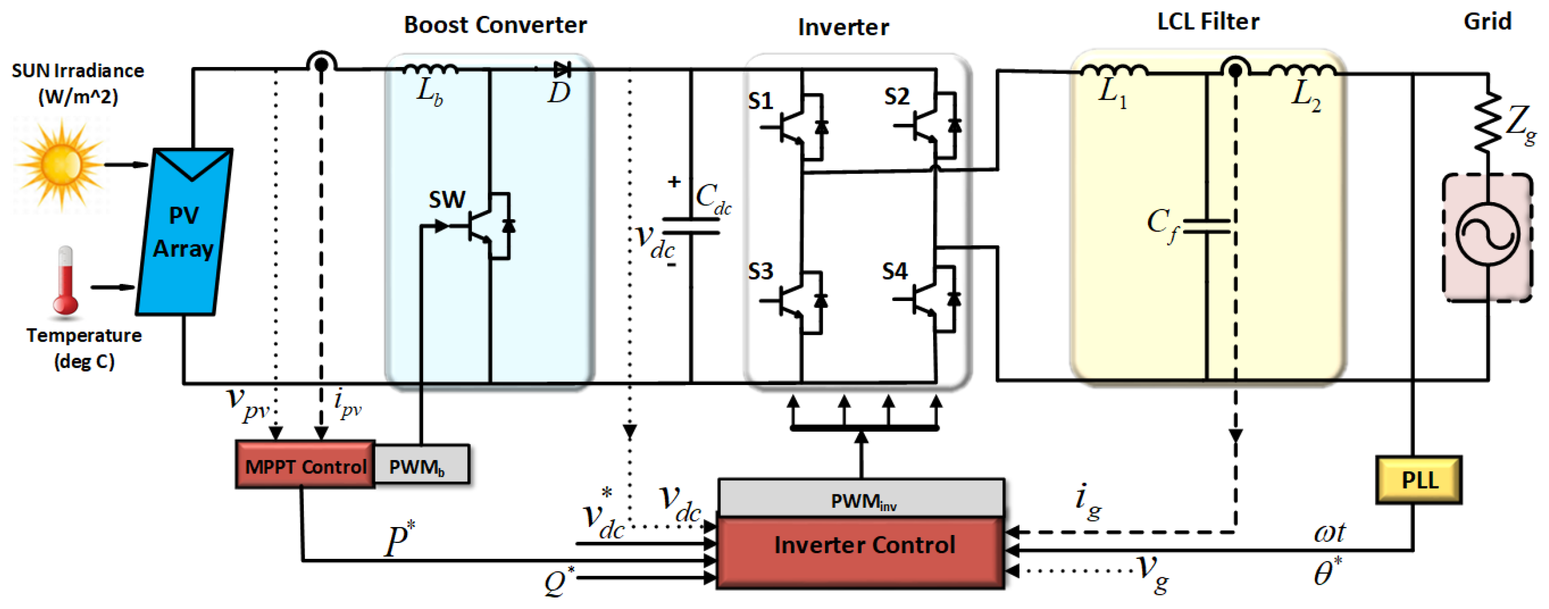
2. Proposed System and Control-Loop Design

Figure 1 shows the structure of the single-phase two-stage transformerless grid-connected PV inverter. The parametric values of the system are given in Table 1. MATLAB®/ Simulink®/Simscape R2017b were used as a control design and simulation platform. For the effective operation of the designed system, control of various parts is mandatory, i.e., the PV side: for maximum power extraction; the inverter side: injection of high-quality current (active and reactive power); and the grid: for ancillary functions. In addition, the consideration of mission profiles (solar irradiance) and ambient temperature are important during the design and planning phase of a PV system as they influence the PV energy [33,34]. Each stage, e.g., the DC-AC inverter and DC-DC converter parts, were completely designed in [3]. This work is an extension of our previously published work [3].

Control of Transformerless PV Inverter

Design of Control Loop

The grid-connected PV system’s control structure consists of dual cascaded loops. The inner loop is recognized as the current-control loop and is used for managing power quality and current protection. The outer loop is the power- or voltage-control loop and is used to generate the references for the current loop [5]. The injected powers (active and reactive) are measured using single-phase PQ theory. The orthogonal signal generator is used to generate v g α and v g β as follows:
P = 1 2 ( v g α i g α + v g β i g β ) , Q = 1 2 ( v g β i g α v g α i g β )
where P is the active power, Q is the reactive power, and i g α β , v g α β are the stationary reference frame’s grid current and voltage, respectively. The current reference is calculated using Equation (1) as follows:
i g α * = 2 ( v g α P * + v g β Q * ) v g α 2 + v g β 2 , i g β * = 2 ( v g β P * v g α Q * ) v g α 2 + v g β 2
In Equation (2), the ‘*’ shows the reference signals. Equation (2) can be written as
i g α * i g β * = 2 v g α 2 + v g β 2 v g α v g β v g β v g α P * Q *
A PI controller is used for power regulation since the P and Q are DC quantities in steady state, as follows:
i g α * i g β * = 2 v g α 2 + v g β 2 v g α v g β v g β v g α G p ( s ) ( P P * ) G q ( s ) ( Q Q * )
where “*” is the reference signal, and the active and reactive powers are regulated using the PI controllers with transfer functions G p ( s ) and G q ( s ) , as follows:
G p s = K p p + K p i 1 s G q ( s ) = K p q + K q i 1 s
Figure 2 presents the control-loop implementation. The DC-link voltage, and the active and reactive powers are regulated with a well-tuned PI controller, while the current-controlled loop employs PR with RHC. As shown in Figure 2, two scenarios are considered: in first case, (a) the input PV power feedforward loop is avoided; while (b) in second case, it is included. The feedforward loop of input PV power improves the overall system dynamics.
For the DC-link controller, the PI controller is employed as follows:
G P I s / DC - link = ( k p + k i s )
where k p and k i are proportional and integral gains, respectively. Then, using Equation (4), the inner current loop reference is calculated. To mitigate the grid distortions, the PR controller with RHC is utilized. In this, the central frequencies of the multiple resonant controllers are allocated at different harmonics, i.e., third, fifth, and seventh. The gains of this controller are set as k p r = 18 , k p i = 2200 , k p i 3 = 1200 , k p i 5 = 800 , k p i 7 = 200 , respectively [34,35].
G P I s / CC = ( k p + k r s s 2 + ω 0 2 ) P R + h = 3 , 5 , 7 k i h s s 2 + ( h ω 0 ) 2 R H C
During normal operation, the grid should inject the maximum possible active power with a power factor close to unity. When a grid fault occurs, the inverter should also inject some reactive power in order to support the grid voltage during recovery. The injection of the reactive power is dependent on the current rating of the inverter and the voltage sage depth. Using Discrete Fourier Transform (DFT), the average and reactive power references are measured as in [5]. The second-order generalized integrator was designed in our previous work [3]. The transfer function is defined as follows:
G I = ω S s 2 + ω 2
where ω is the resonance frequency of SOGI. The closed-loop transfer functions are represented by H d ( s ) and H q ( s ) as
H d ( s ) = v v ( s ) = k ω s s 2 + k ω s + ω 2 , H q ( s ) = q v v ( s ) = k ω 2 s 2 + k ω s + ω 2

3. Proposed Controller Design

3.1. Fuzzy Controller Design

Real-world problems are very complex in nature, and complex problems are basically fuzzy. Fuzzy Logic Controllers (FLC) do not rely on mathematical models and add human logical thinking to the system. FLC can deal with uncertainties as well as nonlinearities. This makes FLC helpful for applications in which models are not properly defined, are complicated, and are nonlinear with parametric variations.
FLC is implemented in four steps as shown in Figure 3. These steps are detailed as follows:
  • Fuzzification: in this step, a fuzzifier uses linguistic variables, terms, and fuzzy membership functions to map real/crisp input data, obtained from the system, to the fuzzy set;
  • Rule-base: this step contains a fuzzy set of rules, a condition, and a conclusion. These IF-THEN rules are used to define the controller action to control the output variables in terms of input variables;
  • Fuzzy inference mechanism: this mechanism controls the plant in the best possible manner by taking expert decisions to interpret and apply the rules;
  • Defuzzification: in this step, de-fuzzifier converts the fuzzy input from the inference mechanism to a real-time/crisp output, which goes to the plant as the controller effort/input.

3.2. Adaptive-PI Controller Design

Conventional PI controllers cannot perform well in the presence of sudden disturbances, parametric variations, and model uncertainties because they use constant values of proportional ( K p ) and integral gains ( K i ). Adaptive-PI (A-PI) controllers solve this problem by adjusting their parameters/gains, as shown in Table 2 and Figure 4.
They use following fuzzy rules to adjust the parameters according to error function:
  • If absolute error | e ( t ) | is small, then K i is zero and K p is large;
  • If | e ( t ) | is large, then both K i and K p are large;
  • If | e ( t ) | = 0 , then K i is smaller while K p is large.
Guassian membership functions are often used in FLC and are expressed as
μ ( x ) = exp ( 1 2 ( x i c i σ i ) 2 )
where c i is the center and σ i is variance or standard deviation.
The PI controller is expressed as
v D C * / i g * ( PI ) = K p e ( t ) + K i e ( t ) d t
where K p and K i are the proportional and integral gains, e ( t ) is the input to the controller, and v D C * / i g is the output of the controller. Equation (11) shows that the proportional and integral gains are fixed and are not able to manage parameter uncertainties, load variations, disturbances, and electrical faults. This problem is solved by the adaptive fuzzy-PI controller because it uses adaptive gains:
v D C * / i g * ( Fuzzy ) = X 1 L 1 e ( t ) + X 2 L 2 e ( t ) d t .
where X 1 and X 2 are the outputs of the fuzzy logic controller, and L 1 and L 2 are the learning rate constants for the gains K p and K i , respectively.

3.3. Adaptive Sliding Mode Controller Design

The Adaptive Sliding Mode Controller (A-SMC) is the combination of fuzzy-PI and Sliding Mode Controller (SMC). The A-SMC combines the favorable features of both controllers. Figure 5 shows the implementation of the F-SMC. Fuzzy IF-THEN rules are used to update the proportional gain ( K p ) and the integral gain ( K i ) of the fuzzy-PI controller [20,36]. The SMC enhances the stability of the system and has a fast transient response. In the first step of the SMC, the sliding surface is defined using error and derivative of error. In the second step of the SMC, a control law is designed for reference tracking [37,38]. The error and its derivative are always directed towards the sliding surface of the SMC.
The sliding surface is defined as follows:
S ( t ) = e ˙ ( t ) + λ e ( t )
where λ is constant and depends on the bandwidth. λ e ( t ) is defined as
λ e ( t ) = X 1 L 1 e ( t ) + X 2 L 2 e ( t )
λ e ( t ) is updated using the fuzzy-PI controller as explained in the previous subsection. The control law is designed as
v D C * / i g * = U s g n ( S ) .
where U is positive gain, S is the sliding surface, and the s g n function is defined as
s g n ( S ( t ) ) = U , if S > 0 U , if S < 0
The control law designed in Equation (15) causes chattering and oscillations. In order to avoid this, the continuous s a t function is used instead of the discontinuous s g n function. This replacement adds continuous approximation to the system and results in a smooth control law, as shown in Equation (17):
v D C * / i g * = U s a t ( σ ; ϵ ) = U S | S | + ϵ ; ϵ > 0

4. Results and Discussion

The performance of the proposed control system was validated by simulating the Fuzzy-Logic-based PI (A-PI) and Fuzzy-Logic-based Sliding Mode Controller (A-SMC) for DC-link voltage control, and active power and reactive power control loops. The implementation platform for the test bench of the 3 kW grid-connected PV system based on two stages with an LCL filter was MATLAB®/Simulink®/PLECS/Simscape. A PR with RHC was used as a current controller for the STGT PV inverter. The current controller was designed with and without the feedforward PV power loop to improve dynamics and control, as presented in case 1 and case 2, respectively. The SOGI-based PLL was utilized for a fast dynamic response, fast tracking accuracy, and harmonic immunity. The system’s nominal parameters, PV panel, and designed controller parameters are given in Table 1, Table A1, Table A2, and Table A3 respectively. The main objectives of the case I and case II experiments were threefold: (i) to check the efficient performance of the DC-link, active power, reactive power, and current-control loops; (ii) to assess the results and compare them with a traditional well-tuned PI controller; (iii) to verify the robustness of the designed controllers.

4.1. Case 1

In this case, the feedforward PV power was avoided and the control loop for active and reactive powers was included. A solar irradiance perturbation was added at 1 s by adjusting 1 kW/ m 2 to 0.6 kW/ m 2 and then to 0.8 kW/ m 2 at 1.2 s. The simulation results were obtained for 3.2 s. The v d c , active power, and reactive power loops were first regulated by the PI controller and then by the A-PI and A-SMC. Figure 6a presents the DC-link voltage response for the designed controllers. Moreover, 1 PU is equivalent to 400 v d c , whereas the error response of this loop is presented in Figure 6b. At the start, the overshoot of the PI controller extended to 1.13 PU, normalizing at 0.9 s, while that of designed controller was 1.05 PU, settling at 0.2 s. When the solar irradiance perturbation occurred, the PI controller demonstrated more sensitivity. In brief, the designed controllers are faster, robust, less sensitive to sudden disturbances and parameter uncertainties, produce less chattering, and have a permissible overshoot and undershoot. Furthermore, the PI error was much higher than that of the designed controllers. Figure 6c demonstrates the active power loop response for the PI controller only. The reference power is well tracked by the actual power. Initially, the behavior is oscillatory, but after 0.35 s, it stabilizes. From 0 s to 1 s, a 3 kW active power (up to nominal value) was injected, from 1 s to 1.2 s, approximately 1.5 kW was injected, as shown in zoom area, and from 1.2 s onwards, 2 kW of active power was injected. A spike can be seen at 2 s and 2.6 s when reactive power was injected and removed. The responses of A-PI and A-SMC are not presented because for every controller, a new reference was generated. However, their responses were fast, efficient, robust, as can be seen from the other results. The reactive power injection of PI and the designed controllers is illustrated in Figure 6d. In order to analyze the operation of the reactive power loop, we can see that, initially, the reference reactive power was zero until 2 s, and at 2 s, 1-kVAR reactive power was injected into the system until 2.6 s. At the start, an oscillation can be seen, which settled after 0.15 s. Similarly, an oscillation in the reactive power occurred between 1 s and 1.2 s due to the variation in the solar irradiance or the active power variation. As can be seen from the zoomed-in areas, the output of the A-PI and A-SMC is robust, fast, reliable, and less oscillatory as compared with a fine-tuned PI controller. Figure 6e provides the grid current and voltage response. The zoomed-in window at 0.54 s to 0.63 s shows that the currents and voltages are in phase. The quality of the current and voltage is a better metric with which to validate the efficient performance of SOGI PLL. At 1 s, the active power decreased due to the solar irradiance, which is why the value of the current decreased accordingly (zoomed-in window from 0.96 s to 1.09 s). As demonstrated in the third zoomed-in window, from 1.8 s to 2.09 s, the current and voltage were out of phase at 2 s because the reactive power was injected. The designed control is exceptionally efficient with high-quality current and voltage. The reference and measured current response using the PR with RHC controller is described in Figure 6f. The controller response was fast, robust, efficient, and less sensitive to solar irradiance variation and reactive power injection. The reference and measured currents were well-tuned with negligible error. Figure 6g shows the PV panel power (input power). The PV panel power was 3 kw until 1 s, from 1 s to 1.2 s, it was approximately 1.5 kW, and thereafter, it was approximately 2 kW. In comparison to the designed controllers, the PI controller was slower, oscillatory, with large spikes, and sensitive to disturbances and variations, as shown in the zoomed-in areas. The designed controller improves the PV power with a stable, reliable, efficient response, is less sensitive to disturbances and uncertainties, and is fast and accurate.

4.2. Case 2

In this case, the PV power was feedforward and the control loop for active and reactive power were included. The simulation results were taken for 3.2 s. A solar irradiance perturbation was added as previously described. The Vdc, active power, and reactive power loops were first regulated by he PI controller and then by the A-PI and A-SMC. The performance of the DC-link voltage is presented in Figure 7a for the designed controllers, while the error response of this loop is presented in Figure 7b. By comparing the results with Figure 6, in this case, both the steady-state and dynamic responses were greatly improved, i.e., the PI controller response was slower and showed sensitivity towards sudden disturbances, as illustrated in the zoomed-in area. The A-PI and A-SMC demonstrated faster responses and lower sensitivity to parameter uncertainty and sudden disturbances. The initial spike in the Vdc for the PI controller was 0.08 PU, while for the A-PI and A-SMC, it was negligible. In addition, the overshoot, undershoot, and settling time of the PI controller were much higher than for the designed control loops. This can also be noted in the error response. Furthermore, the error response for the PI controller demonstrated a higher variation. The active power loop response is presented in Figure 7c for the PI controller. The actual power tracked the reference power well. Initially, the behavior was oscillatory, but after 0.2 s, it stabilized. From 0 s to 1 s, a 3 kW active power (up to a nominal value) was injected, from 1 s to 1.2 s, approximately 1.5 kW was injected, as shown in the zoomed-in area, and from 1.2 s, 2 kW active power was injected. A spike can be seen at the 2 s injection and the removal of reactive power at 2.6 s. The responses of the A-PI and A-SMC are not presented as for every controller, a new reference was generated. However, their response was fast, efficient, robust as can be seen from other results. Figure 7d represents the reactive power injection. The reference reactive power was zero until 2 s, and at 2 s, 1 kVAR of reactive power was injected into the system until 2.6 s, in order to analyze the operation of reactive power loop. The start oscillation at the beginning settled after 0.2 s. Similarly, the oscillation in the reactive power occurred at 1 s to 1.2 s due to the variation in the solar irradiance and active power. As can be seen from the zoomed-in areas, the output of the A-PI and A-SMC was fast, robust, reliable, and less oscillatory as compared with the well-regulated PI controller.
The grid voltage and current response are presented in Figure 7e. The zoomed-in window at 0.58 s to 0.67 s shows that the currents and voltages are in phase. The quality of the current and voltage is a better metric for validating the performance of SOGI PLL. At 1 s, the active power decreased due to the solar irradiance, which is why the value of the current decreased accordingly. As demonstrated in the third zoomed-in window, from 1.9 s to 2.2 s, the current and voltage were out of phase at 2 s because of the injection of reactive power. The designed control is exceptionally efficient. Figure 7f shows the references and measured current response using the PR with RHC controllers. The controller response was fast, robust, efficient, and insensitive to solar irradiance variation and reactive power disturbance. The PV panel power is presented in Figure 7g. The PV panel power was 3 kW until 1 s, from 1 s to 1.2 s, it was approximately 1.5 kW, and thereafter, it was approximately 2 kW. In comparison to A-PI and A-SMC, the response of the PI controller was slower, it was oscillatory, with large spikes, and it was sensitive to disturbances and variations, as shown in the zoomed-in areas. The designed controller improved the PV power with a globally stable, reliable, fast response.

5. Conclusions

In this study, DC-link voltage, active power, and reactive power were successfully controlled in stationary reference using A-PI and A-SMC for a 3 kW two-stage single-phase transformerless grid-connected inverter. A PR with RHC is employed in the current-controlled loop. The phase information is provided by PLL, known as SOGI, which has harmonic immunity, fast tracking accuracy, and a fast dynamic response. Two scenarios are considered: in first case, the input PV power is not feedforward, while in second case, it is feedforward. The results demonstrate that the designed controller improves both the dynamic and steady-state performance as compared with a well-regulated PI controller. The proposed controllers are insensitive to active and reactive power variations, and are robust, stable, faster, and fault tolerant. In addition, the feedforward loop of the input PV power improves the overall system dynamics. The PV panel power is improved and its quality is enhanced. The injected current is of high quality and well controlled with negligible distortion.
In the foreseeable future, the simulation responses obtained will be validated using DSP TMS320F28335, FPGA, or DSPACE hardware boards. Next generation switching devices, i.e., Silicon Carbide (SiC) and Gallium Arsenide (GaN) will be replaced on MOSFET and IGBT to further enhance the efficiency of the system. Advanced controllers, e.g., a higher order sliding mode controller, a fuzzy-neural network, h-infinity, feedback linearization control, adaptive L1, etc., will be designed and compared with a well-tuned PI and with the controller designed in this paper to provide a better comparison. In addition, the heating effect produced by the ripple current in the DC-link capacitor causes vaporization and degradation of aluminum electrolytic capacitor, which should be addressed in forthcoming studies by designing online monitoring techniques. Furthermore, the H-bridge inverter can be replaced by another H-bridge (H-5, H-6, HERIC etc.) and neutral point clamped topologies to obtain better results.

Author Contributions

K.Z.: idea, mathematical modeling, implementation, results, analysis and writing manuscript. M.S.N.: Writing, formatting, final drafting I.A. and W.U.: revising manuscript and monitoring, and H.-J.K.: supervision and funding. All authors are involved in improving the overall contents of the manuscript and have read and agreed to this published version of the manuscript.

Funding

This Research was Supported by BK21PLUS. We also acknowledged NUST.

Conflicts of Interest

The authors declare no conflict of interest.

Appendix A

Table A1. PV panel nominal parameters.
ParametersSymbolsValues
Grid voltage (RMS) P m p p 65 W
Open circuit voltage V O C 21.7 V
Short circuit current I S C 3.99 A
MPPT voltage V m p p 17.6 V
MPPT current I m p p 3.69 A
Table A2. Control gains without PV power feedforward loop.
Control StrategiesDC-Link Loop (V)Active Power (P)Reactive Power (Q)
PI k p = 32 × 400, k i = 280 × 400 k p p = 11.2, k p i = 35.5 k q p = 1.2, k q i = 60.5
A-PI k 1 = 110, k 2 = 1080 k p p = 11.2, k p i = 135.5 k q p = 1.2, k q i = 155.5
A-SMC k 1 = 280, k 2 = 2980, ϵ = 150 k p p = 60.2, k p i = 280.5 k q p = 3.2, k q i = 315.5
Table A3. Control gains with PV power feedforward loop.
Control StrategiesDC-Link Loop (V)Active Power (P)Reactive Power (Q)
PI k p = 32 × 400, k i = 280 × 400 k p p = 11.2, k p i = 35.5 k q p = 1.2, k q i = 60.5
A-PI k 1 = 110, k 2 = 1080 k p p = 11.2, k p i = 135.5 k q p = 1.2, k q i = 155.5
A-SMC k 1 = 280, k 2 = 2980, ϵ = 150 k p p = 60.2, k p i = 280.5 k q p = 3.2, k q i = 315.5
PR + RHC k p = 18, k r = 2200
k i 3 third harmonic’s compensation = 1200
k i 5 fifth harmonic’s compensation = 800
k i 7 seventh harmonic’s compensation = 200

References

  1. Khan, M.A.; Kurukuru, V.B.; Haque, A.; Mekhilef, S. Islanding Classification Mechanism for Grid-Connected Photovoltaic Systems. IEEE J. Emerg. Sel. Top. Power Electron. 2020. [Google Scholar] [CrossRef]
  2. Zeb, K.; Uddin, W.; Khan, M.A.; Ali, Z.; Ali, M.U.; Christofides, N.; Kim, H. A comprehensive review on inverter topologies and control strategies for grid connected photovoltaic system. Renew. Sustain. Energy Rev. 2018, 94, 1120–1141. [Google Scholar] [CrossRef]
  3. Zeb, K.; Islam, S.U.; Din, W.U.; Khan, I.; Ishfaq, M.; Busarello, T.D.C.; Ahmad, I.; Kim, H.J. Design of fuzzy-PI and fuzzy-sliding mode controllers for single-phase two-stages grid-connected transformerless photovoltaic inverter. Electronics 2019, 8, 520. [Google Scholar] [CrossRef] [Green Version]
  4. Kabalcı, E. Review on novel single-phase grid-connected solar inverters: Circuits and control methods. Sol. Energy 2020, 198, 247–274. [Google Scholar] [CrossRef]
  5. Yang, Y.; Blaabjerg, F. Low-voltage ride-through capability of a single-stage single-phase photovoltaic system connected to the low-voltage grid. Int. J. Photoenergy 2013, 2013, 257487. [Google Scholar] [CrossRef] [Green Version]
  6. Yang, Y.; Wang, H.; Blaabjerg, F. Reactive power injection strategies for single-phase photovoltaic systems considering grid requirements. IEEE Trans. Ind. Appl. 2014, 50, 4065–4076. [Google Scholar] [CrossRef] [Green Version]
  7. Islam, S.U.; Zeb, K.; Din, W.U.; Khan, I.; Ishfaq, M.; Hussain, A.; Busarello, T.D.C.; Kim, H.J. Design of robust fuzzy logic controller based on the levenberg marquardt algorithm and fault ride trough strategies for a grid-connected PV system. Electronics 2019, 8, 429. [Google Scholar] [CrossRef] [Green Version]
  8. Bak, Y.; Lee, J.S.; Lee, K.B. Low-voltage ride-through control strategy for a grid-connected energy storage system. Appl. Sci. 2018, 8, 57. [Google Scholar] [CrossRef] [Green Version]
  9. Bighash, E.Z.; Sadeghzadeh, S.M.; Ebrahimzadeh, E.; Blaabjerg, F. Improving performance of LVRT capability in single-phase grid-tied PV inverters by a model-predictive controller. Int. J. Electr. Power Energy Syst. 2018, 98, 176–188. [Google Scholar] [CrossRef]
  10. Al-Shetwi, A.Q.; Sujod, M.Z.; Blaabjerg, F. Low voltage ride-through capability control for single-stage inverter-based grid-connected photovoltaic power plant. Sol. Energy 2018, 159, 665–681. [Google Scholar] [CrossRef] [Green Version]
  11. Chen, H.C.; Lee, C.T.; Cheng, P.T.; Teodorescu, R.; Blaabjerg, F. A low-voltage ride-through technique for grid-connected converters with reduced power transistors stress. IEEE Trans. Power Electron. 2016, 31, 8562–8571. [Google Scholar] [CrossRef]
  12. Arulkumar, K.; Palanisamy, K.; Vijayakumar, D. Recent advances and control techniques in grid connected PV system—A review. Int. J. Renew. Energy Res. 2016, 6, 1037–1049. [Google Scholar]
  13. Haidar, A.M.; Julai, N. An improved scheme for enhancing the ride-through capability of grid-connected photovoltaic systems towards meeting the recent grid codes requirements. Energy Sustain. Dev. 2019, 50, 38–49. [Google Scholar] [CrossRef]
  14. Patsalides, M.; Stavrou, A.; Efthymiou, V.; Georghiou, G.E. Towards the establishment of maximum PV generation limits due to power quality constraints. Int. J. Electr. Power Energy Syst. 2012, 42, 285–298. [Google Scholar] [CrossRef]
  15. Ahmad, M.W.; Kumar, P.N.; Arya, A.; Anand, S. Noninvasive technique for DC-link capacitance estimation in single-phase inverters. IEEE Trans. Power Electron. 2017, 33, 3693–3696. [Google Scholar] [CrossRef]
  16. Zakzouk, N.E.; Abdelsalam, A.K.; Helal, A.A.; Williams, B.W. PV single-phase grid-connected converter: Dc-link voltage sensorless prospective. IEEE J. Emerg. Sel. Top. Power Electron. 2016, 5, 526–546. [Google Scholar] [CrossRef] [Green Version]
  17. Hu, Y.; Du, Y.; Xiao, W.; Finney, S.; Cao, W. DC-link voltage control strategy for reducing capacitance and total harmonic distortion in single-phase grid-connected photovoltaic inverters. IET Power Electron. 2015, 8, 1386–1393. [Google Scholar] [CrossRef]
  18. He, F.; Zhao, Z.; Yuan, L.; Lu, S. A DC-link voltage control scheme for single-phase grid-connected PV inverters. In Proceedings of the 2011 IEEE Energy Conversion Congress and Exposition, Phoenix, AZ, USA, 17–22 September 2011; pp. 3941–3945. [Google Scholar]
  19. Zakzouk, N.; Abdelsalam, A.; Helal, A.; Williams, B. DC-link voltage sensorless control technique for single-phase two-stage photovoltaic grid-connected system. In Proceedings of the 2014 IEEE International Energy Conference (ENERGYCON), Cavtat, Croatia, 13–16 May 2014; pp. 58–64. [Google Scholar]
  20. Zeb, K.; Din, W.U.; Khan, M.A.; Khan, A.; Younas, U.; Busarello, T.D.C.; Kim, H.J. Dynamic Simulations of Adaptive Design Approaches to Control the Speed of an Induction Machine Considering Parameter Uncertainties and External Perturbations. Energies 2018, 11, 2339. [Google Scholar] [CrossRef] [Green Version]
  21. Zeb, K.; Islam, S.U.; Uddin, W.; Khan, I.; Ishfaq, M.; Busarello, T.D.C.; Kim, H. High-Performance and Multi-Functional Control for Transformerless S ingle-Phase Smart Inverter for Grid-connected PV System. J. Mod. Power Syst. Clean Energy 2020. [Google Scholar] [CrossRef]
  22. Zeb, K.; Busarello, T.D.C.; Ul Islam, S.; Uddin, W.; Raghavendra, K.V.G.; Khan, M.A.; Kim, H.J. Design of Super Twisting Sliding Mode Controller for a Three-Phase Grid-connected Photovoltaic System under Normal and Abnormal Conditions. Energies 2020, 13, 3773. [Google Scholar] [CrossRef]
  23. Islam, S.U.; Zeb, K.; Din, W.U.; Khan, I.; Ishfaq, M.; Busarello, T.D.C.; Kim, H.J. Design of a proportional resonant controller with resonant harmonic compensator and fault ride trough strategies for a grid-connected photovoltaic system. Electronics 2018, 7, 451. [Google Scholar] [CrossRef] [Green Version]
  24. Seyedalipour, S.S. A Novel Deadbeat Control for Three-Phase Grid-Connected VSI with an Output LCL Filter in Natural Frame. In Proceedings of the 2019 International Power System Conference (PSC), Tehran, Iran, 9–11 December 2019; pp. 447–452. [Google Scholar]
  25. Nguyen-Van, T.; Abe, R.; Tanaka, K. MPPT and SPPT control for PV-connected inverters using digital adaptive hysteresis current control. Energies 2018, 11, 2075. [Google Scholar] [CrossRef] [Green Version]
  26. Hassan, S.Z.; Li, H.; Kamal, T.; Arifoğlu, U.; Mumtaz, S.; Khan, L. Neuro-Fuzzy wavelet based adaptive MPPT algorithm for photovoltaic systems. Energies 2017, 10, 394. [Google Scholar] [CrossRef] [Green Version]
  27. Zeb, K.; Islam, S.U.; Uddin, W.; Ullah, K.; Asghar, R.; Busarello, T.; Kim, H.J. DC-link Voltage Regulation of Single-Phase Grid-Tied PV System using Fuzzy-PI Controller. In Proceedings of the 2019 15th International Conference on Emerging Technologies (ICET), Peshawar, Pakistan, 2–3 December 2019; pp. 1–6. [Google Scholar]
  28. Mukherjee, S.; Chowdhury, V.R.; Shamsi, P.; Ferdowsi, M. Model reference adaptive control based estimation of equivalent resistance and reactance in grid-connected inverters. IEEE Trans. Energy Convers. 2017, 32, 1407–1417. [Google Scholar] [CrossRef]
  29. Zhang, X.; Chen, P.; Yu, C.; Li, F.; Do, H.T.; Cao, R. Study of a current control strategy based on multisampling for high-power grid-connected inverters with an LCL filter. IEEE Trans. Power Electron. 2016, 32, 5023–5034. [Google Scholar] [CrossRef]
  30. Ishfaq, M.; Uddin, W.; Zeb, K.; Khan, I.; Ul Islam, S.; Adil Khan, M.; Kim, H.J. A new adaptive approach to control circulating and output current of modular multilevel converter. Energies 2019, 12, 1118. [Google Scholar] [CrossRef] [Green Version]
  31. Uddin, W.; Zeb, K.; Adil Khan, M.; Ishfaq, M.; Khan, I.; Islam, S.u.; Kim, H.-J.; Park, G.S.; Lee, C. Control of output and circulating current of modular multilevel converter using a sliding mode approach. Energies 2019, 12, 4084. [Google Scholar] [CrossRef] [Green Version]
  32. Khan, I.; Zeb, K.; Din, W.U.; Islam, S.U.; Ishfaq, M.; Hussain, S.; Kim, H.-J. Dynamic modeling and robust controllers design for doubly fed induction generator-based wind turbines under unbalanced grid fault conditions. Energies 2019, 12, 454. [Google Scholar] [CrossRef] [Green Version]
  33. Hassan, Z.; Amir, A.; Selvaraj, J.; Rahim, N.A. A review on current injection techniques for low-voltage ride-through and grid fault conditions in grid-connected photovoltaic system. Sol. Energy 2020, 207, 851–873. [Google Scholar] [CrossRef]
  34. Blaabjerg, F.; Ionel, D.M. Renewable Energy Devices and Systems with Simulations in Matlab® and Ansys®; CRC Press: Boca Raton, FL, USA, 2017. [Google Scholar]
  35. Yang, Y.; Blaabjerg, F.; Wang, H.; Simoes, M.G. Power control flexibilities for grid-connected multi-functional photovoltaic inverters. IET Renew. Power Gener. 2016, 10, 504–513. [Google Scholar] [CrossRef] [Green Version]
  36. Zeb, K.; Uddin, W.; Haider, A.; Belal, S.; Mehmood, C.; Khan, M.; Kim, H. Robust speed regulation of indirect vector control induction motor using fuzzy logic controllers based on optimization algorithms. Electr. Eng. 2018, 100, 787–802. [Google Scholar] [CrossRef]
  37. Zhu, Y.; Fei, J. Disturbance observer based fuzzy sliding mode control of PV grid connected inverter. IEEE Access 2018, 6, 21202–21211. [Google Scholar] [CrossRef]
  38. Fang, Y.; Zhu, Y.; Fei, J. Adaptive intelligent sliding mode control of a photovoltaic Grid-connected inverter. Appl. Sci. 2018, 8, 1756. [Google Scholar] [CrossRef] [Green Version]
Figure 1. Block diagram of proposed grid-connected PV system with dual stages.
Energies 14 02546 g001
Figure 2. Design of control loop (a) with and (b) without feedforward power of PV, individually.
Energies 14 02546 g002
Figure 3. Fuzzy controller architecture.
Energies 14 02546 g003
Figure 4. Adaptive PI controller.
Energies 14 02546 g004
Figure 5. Adaptive sliding mode controller.
Energies 14 02546 g005
Figure 6. (a) The performance of DC-link voltage tested for the designed controllers; (b). Error response for PI, A-PI, and A-SMC. (c) Active power loop response for the PI controller. (d) Reactive power injection for the designed controllers. (e) Grid voltage and current. (f) Grid currents using PR and RHC. (g) Power of the PV panel for the designed controllers.
Energies 14 02546 g006
Figure 7. (a) The performance of DC-link voltage tested for the designed controllers; (b). Error response for PI, A-PI, and A-SMC. (c) Active power-loop response for PI controller. (d) Reactive power injection for designed controllers. (e) Grid voltage and current. (f) Grid currents using PR and RHC. (g) Power of PV panels for the designed controllers.
Energies 14 02546 g007aEnergies 14 02546 g007b
Table 1. Nominal values of proposed grid-connected PV system.
SpecificationSymbolsValues
DC-link voltage reference V d c * 400 V
Boost inductance L b 20 mH
Switching frequency of boost-converter f b 20 KHz
LCL filter L 1 , C f , L 2 1.5 mH, 2.35 F, 1.8 mH
DC-link voltage capacitance C d c 2200 F
Switching frequency of inverter f i n v 10 KHz
RMS voltage of grid V g 230 V
Operating frequency of grid ω g 314 rad/s
Impedance of grid L g , R g 0.5 mH, 0.2 Ω
Table 2. Adaptive-PI and A-SMC IF-THEN rules.
S. No.Input Membership FunctionRulesOutput Membership Function
1.Linguistic Term: zero, Range: [0,0.2]IF Input: zero THEN Output: zeroLinguistic Term: zero, Range: [0,0.2]
2.Linguistic Term: small, Range: [0.3,0.7]IF Input: small THEN Output: smallLinguistic Term: small, Range: [0.3,0.7]
3.Linguistic Term: large, Range: [0.8,1.0]IF Input: large THEN Output: largeLinguistic Term: large, Range: [0.8,1.0]
Publisher’s Note: MDPI stays neutral with regard to jurisdictional claims in published maps and institutional affiliations.

