1. Introduction
The detrimental environment pollution due to the use of conventional sources of energy, the continuous increases in the price of oil and the expected eventual exhaustion of fossil fuels have fostered the rapid development of electric vehicles, both battery-based (BEV), hybrid (HEV), plug-in (PEV) and fuel cell-based (FCEV) [
1,
2]. Some European countries, such as Norway and Sweden have scheduled banning all petrol-powered cars in the next 3–4 decades. The EVs inherently linking the transport and the electricity sectors have given rise to emerging technologies such as superchargers (G2V) and grid-support (V2G) [
3,
4,
5]. These EVs are grid-connected through a power converter, hence requiring of advanced power conversion and control techniques and a deep analysis of the grid impact, the converter behavior, the stability, the harmonic emission and the electromagnetic interference (EMI) [
6]. There exists a wide variety of EV battery charger topologies [
7]. The dual active full bridge (DAFB) and the dual active half bridge (DAHB) DC-DC topologies are especially practical because they include a higher frequency (HF) transformer in between that provides a galvanic isolation for safely connecting the EV batteries with the mains through the grid-tied power converter [
8,
9]. Furthermore, bearing in mind that the physical size and in turn the weight of the required transformer reduces with the increasing of the operating frequency [
10], this topology is fairly attractive for EV applications where space and burden constraints are critical. Despite the fact that in the DAHB topology only the SPS control technique can be applied, it is widely utilized due to its low cost, volume and weight as well as its global reduction in switches, drivers and cooling system [
11].
The interaction of modern power converters with the smart grid is a main issue regarding power quality aspects [
12]. The use of multilevel power converters (ML) is increasingly preferred since they provide a high-quality output voltage with a lower harmonic content, a lower dV/dt, a lower switching frequency and consequently a higher efficiency [
13]. The cascaded H-bridge (CHB), the flying capacitor (FC) and the neutral-point-clamped (NPC) including its subtopology of active-NPC (ANPC) are the main types of conventional multilevel topologies [
14]. The NPC-based configurations have the advantage of requiring only one isolated DC source but also the inconvenient that its DC-link split capacitors undergo the voltage unbalance phenomenon and consequently they need implementing balancing compensation techniques [
15,
16,
17,
18]. It is possible to get rid of this unbalancing issue by using two independent DC voltage sources instead of capacitors but at the expense of a higher cost and a bigger system complexity [
19] or well in certain photovoltaic (PV) applications [
20].
Over the last years various topologies of single-phase ANPC five-level (FL) converters have been devised. In [
21], authors propose a single-phase hybrid Si/SiC ANPC FL inverter with an improved modulation scheme for reducing the conduction losses. Although the inherent voltage unbalancing problem is not mentioned, its undesirable effect is present but it could have been reduced by considerably increasing the capacitance of the electrolytic split capacitors. Due to the absence of redundant vectors for the states that output half of the DC bus voltage, the voltage balancing in this topology is simply not possible. In [
22], authors propose a single-phase ANPC FL inverter and its three-phase version. The modulation strategy is based on an unipolar pulse-width modulation (PWM) for the high-frequency switches and on the polarity of the modulating signal for the low-frequency switches. Owing to the consecutive alternation of the redundant switching states for the high-frequency switches, the split capacitors are equally charge and discharge at each switching period, thus accurately maintaining a zero average neutral current and consequently achieving a fairly good voltage unbalancing compensation. Nevertheless, the alternation of the redundant states at twice the switching frequency increases the power losses and the stress of the high frequency switches, thus reducing the overall efficiency.
In comparison with [
21,
22], the single-phase (SP) ANPC-FL converter proposed in this paper is based on a novel topology consisting of ten switches instead of eight. However, with the addition of these two switches, it not only becomes capable of properly balancing the voltage of the DC-link split capacitors under different step-changing conditions but it achieves a better efficiency, a lower stress of the switching devices and a more even distribution of the power losses. Thanks to this voltage balancing, the power quality of the proposed ANPC-FL converter output voltage and in turn of the grid current are considerably enhanced during the G2V and V2G operation of the cascaded DAHB converter working as a bidirectional EV charger.
This paper is organized as follows:
Section 2 describes the topology details of the proposed ANPC SPFLBC, its current flowing paths and its voltage balancing strategy.
Section 3 examines the cascaded control strategy for the proposed grid-tied SPFLBC while analyzes the DAHB converter and its SPS control technique.
Section 4 shows the transient and steady state simulation results obtained with MATLAB-SimPowerSystems whereas the experimental results obtained in laboratory are presented in
Section 5. For this, several tests and measurements under different conditions have been carried out including also the power quality and power losses distribution analyses.
Section 6 provides the discussion. Finally, the conclusion and some important remarks are given in
Section 7.
3. Control of Proposed Grid-Tied ANPC SP Five-Level Converter and Cascaded DAHBC
Figure 3 shows the block diagram of the proposed grid-tied ANPC SPFLBC and the EV charger based on the DAHB converter with HF isolation transformer. For ease of readability, the details of the cascaded control strategy block included in
Figure 3 are shown in the diagram of
Figure 4.
Figure 5 shows the scheme of the cascaded control strategy carried out for regulating the DC bus voltage
and the grid-current
using two controllers connected in series [
24]. For this, the PLL first synchronizes with the grid voltage
and provides a unit sinusoidal reference signal. Then, it multiplies with the output from the
compensator of the outer voltage for generating the grid current reference
that becomes the input of the cascaded current inner loop. Later, the output from the current compensator
is subtracted from the grid voltage for providing the reference
of the multicarrier phase-disposition PWM [
24,
25]. Finally, the resulting state is sent to the voltage balancing block that generates the ten switching signals
of the ANPC SPFLBC.
The maths behind the cascaded controller are described in the following. The outer loop voltage error
and the inner loop current error
are defined as:
where the superscript * means a reference signal. In the outer loop there is a proportional integral (PI) voltage compensator whereas in the inner loop there is a proportional-resonant (PR) current controller, respectively. By applying the Kirchhoff’s voltage law (KVL) to the power circuit of
Figure 3 consisting in the ANPC SPFLBC connected with the single-phase AC grid through an RL line, the following equation is obtained:
where the variables
and
represent the line resistance and line inductance while
,
and
mean the grid current, the grid voltage and the ANPC SPFLBC output voltage, respectively. The converter output voltage can also be expressed as a function of the duty cycle
δ as follows:
By substituting (4) in (3) and assuming an average value for the grid current and the respective duty cycle, the small signal model of the grid current is given by:
Assuming that the inner current loop is ten times faster than the outer voltage loop,
is seen as a constant value that does not vary with time and consequenlty
. Hence, the transfer function
for the inner current loop is written as:
Bearing in mind that the inner loop deals with the grid current that is an ac quantity, thus a proportional-resonant controller with a zero-steady state error and a theoretical infinite gain at the resonance frequency has been used [
26]. The transfer function
of this current controller is given by:
After applying the Kirchhoff’s current law (KCL) at the node
in the power circuit of
Figure 3, the following equations are obtained:
where
is the split capacitors current and
. By substituting (4) into (11) and the resulting (9)–(11) into (8) while assuming an average value for the grid current and the duty cycle, the small signal model that links up the dc bus voltage with the grid current is found as:
By considering in (12) the same assumption as in the inner loop, i.e.,
, the transfer function
for the outer voltage loop is derived as:
Bearing in mind that the outer loop deals with the bus voltage that is a dc quantity, thus a classical proportional-integral controller has been used. The transfer function
of this voltage controller is given by:
By programming the transfer functions of the plants (6), (13) and the compensators (7), (14) in MATLAB code and using the single-input single-output (SISO) design tool, the gains of the controller have been accurately tuned until obtaining a good response [
24].
Dual Active Half-Bridge DC-DC Converter
The EV bidirectional charger studied in this paper is based on the dual-active half-bridge DC-DC converter which has an advantageous isolation high-frequency transformer in between. As shown in
Figure 3, the EV battery bank is connected on the low-voltage side of the DAHBC whereas the proposed ANPC SPFLBC is connected on the high-voltage side. The topology of this DAHB converter consists of one arm with two switches and another arm with two split capacitors. The set of these two arms are found at either side of the HF transformer [
27]. The DAHBC can either increase or decrease the voltage from either side, thereby it is capable of working as a bidirectional Boost/Buck voltage converter. The direction and magnitude of the power flow is controlled by shifting the relative phase between the voltages on either side of the HF transformer. In comparison with the dual active full bridge converter (DAFBC), the DAHBC replaces four of its switches with four capacitors. This reduction in the number of power switches represents a limitation in terms of the available degrees of liberty for controlling the power flow. However, it becomes an important advantage regarding the inherent lower switching and conduction losses. Furthermore, in the DAHBC the unique four power switches available also experiment a lower stress since they have to endure only half of the DC bus voltage. Another advantage of this simplified topology is that in steady state, the magnetizing current of the HF transformer does not contain any dc component, thereby not increasing the core losses or giving rise to flux saturation [
28].
The DAHB converter and its control blocks are shown in
Figure 3. The switching signals
and
as well as
and
are obtained by comparing the triangular carrier signal
with zero, thus both sides of the DAHBC operate at a fixed-duty cycle of 50%. However, the phase of pulses
/
are shifted with respect to
/
within the SPS block in accordance to the desired battery current and its sign. During the V2G mode, the pulses
/
lag
/
whereas in the G2V mode, the pulses
/
lead
/
. The current flowing paths for the different switching states of the DAHBC can be found in [
29]. According to the experimental sizing of the ANPC SPFLBC, the DAHBC, the EV batteries bank and the variac connected to the grid, the main parameters of the HF transformer have been determined by simulation.
Figure 6 shows the commercial off-the-shelf (COTS) HF transformer used in the prototype of the DAHBC built in the laboratory.
4. Simulation Results
With the aim of validating and evaluating the performance of the proposed grid-tied ANPC SPFLBC and the cascaded DAHBC, the full system presented in
Figure 3 has been simulated in MATLAB-SimPowerSystems. For this, the following five tests have been carried out: (a) A step-change in the battery current under the V2G mode, (b) A step-change in the battery current under the G2V mode, (c) A grid voltage sag/swell under the V2G mode d) A DC bus voltage step-change under the G2V mode and (e) A swept of the capacitance of the DC-link split capacitors. The obtained results are presented in
Figure 7,
Figure 8,
Figure 9,
Figure 10 and
Figure 11.
In the first test, as it is shown in
Figure 7, the battery current reference
has been step-changed from +4.75 A to +9.5 A and back to +4.75 A after 75 ms. Bearing in mind that the sign of the battery current is positive, thus the power is flowing from the battery to the grid. i.e., V2G mode, and the grid current
is out-of-phase with the grid voltage
. It can be observed that from
= 0.2 s when the voltage balancing strategy is activated, the voltage of split capacitors becomes equal and thus the levels of the ANPC SPFLBC output voltage
become symmetric and undistorted. Note also that the SPS control technique applied to the DAHBC properly regulates the battery current with a fast response, equivalent to a good dynamic on the grid side. The DC bus voltage is alike fairly good maintained at 500 V in spite of the abrupt changes in the current flowing through the five-level converter.
In the second test, as it is shown in
Figure 8,
has been step-changed from −3.75 A to −7.5 A and back to −3.75 A after 75 ms. Bearing in mind that the sign of the battery current is negative, thus the power is flowing from the grid to the battery. i.e., G2V mode, and the grid current
is in-phase with the grid voltage
. Note that the −7.5 A from the battery is equivalent to a grid current with a peak value of around 20 A. This is due to the different voltage ratio between the DC bus and the AC grid. The parameters of the simulated and the experimental prototype can be consulted in
Table 3. As in the V2G mode, the voltage balancing alike improves the power quality of
and in turn of
while the DC bus voltage and the battery current are properly controlled.
In the third test, as it is shown in
Figure 9,
is kept constant at +9.5 A (V2G mode) while the peak value of the grid voltage is first decreased from 390 V to 340 V and later increased back to 390 V. These sag and swell are equivalent to 12.8% and 14.7%, respectively. It can be noted how before
= 0.2 s, the voltage unbalance increases with the grid voltage reduction. However, once the voltage balancing strategy is activated, it makes equal the voltages of the upper
and lower
capacitors in spite of the grid voltage variations. Additionally, the effect on the DC bus voltage regulation becomes negligible.
In the fourth test, as it is shown in
Figure 10,
is kept constant at −7.50 A (G2V mode) while the DC bus voltage reference
is step-changed from 500V to 550 V and back to 500 V. These variations are equivalent to 10% and 9.1%, respectively. As in the previous tests, the voltage balancing strategy also makes that the split capacitors voltages accurately match, and in turn it allows achieving a fairly good symmetry of
and a considerable reduction in the harmonic distortion of
.
In the fifth test, as it is shown in
Figure 11, the capacitance of the DC-link split capacitors
=
has been linearly varied following the profile of a triangular wave with peak values of 1 mF and 100 µF. The total harmonic distortion (THD) as well as the split capacitors voltage waveforms for the V2G and G2V modes have been obtained with a battery current refence
of +9.5 A and −7.5 A, respectively. It can be observed that the highest THD and maximum capacitors unbalance occur when the capacitance is minimum, i.e., at 100 µF. However, it is important to remark how even under the worst conditions in both operation modes, the proposed voltage balancing strategy significantly narrows the capacitors voltage difference from around 200 V to less than 6 V. In the same way, the maximum THD of
in the V2G and G2V operations modes quite decreases from 9.4% and 10.0% to around 1.5% in both cases. Likewise, the highest THD of
in the V2G and G2V operation modes fairly reduces from 19.9% and 27.4% to only 4.3% and 4.5%, respectively.
5. Experimental Results
In order to validate and evaluate the performance of the voltage balancing and cascaded control strategies for the proposed grid-tied SPFLBC as well as of the SPS technique for the battery current control through the DAHBC, they have been built and tested on the same basis of the simulations described in
Section 4. The parameters of these converters are summarized in
Table 3.
Figure 12 shows a photograph of the full experimental setup built in laboratory whereas
Figure 13,
Figure 14,
Figure 15,
Figure 16,
Figure 17,
Figure 18 and
Figure 19 show the obtained results.
Figure 13 shows the performance of the ANPC SPFLBC and the DAHBC during a step-change in the battery current under the V2G mode. At
= 1.5 s, the battery current reference
is changed from +0.175 A to +0.350 A and back to +0.175 A after 2 s. This sequence repeats at half the full-time scale, i.e., at
= 5 s when the voltage balancing is activated. It can be observed how the voltage unbalance of split capacitors increases with the battery current. However, the voltage balancing strategy is very effective by making practically equals the voltages of the upper capacitor
and the lower capacitor
.
During this time, the DC bus voltage is accurately maintained at 24V in spite of the disturbances caused by the sudden variations in the current flow from the battery to the grid. It can also be noted that initially the output voltage waveform from the ANPC SPFLBC is asymmetric due to the unbalance in states 2 and 4 while the grid current is severely distorted. Thanks to the proposed voltage balancing, the ANPC SPFLBC provides a voltage signal with high symmetry that in turn allows flowing a high-quality grid current with very low harmonic content. Furthermore, accurately remains out-of-phase with the grid voltage since the grid is receiving the power from the battery. It is important to clarify that the voltage and current spikes observed in the waveforms do not belong to the real measurements but to the EMI induced in the probes of the TPS2024B Tektronix scope. Given that this instrument does not incorporate any kind of filtering, the displayed signals are purely raw.
Figure 14 shows the performance of the ANPC SPFLBC and the DAHBC during a step-change in the battery current under the G2V mode. At
= 1.5s, the battery current reference
is changed from −0.175 A to −0.350 A and back to −0.175 A after 2 s. It is noteworthy how after the activation of the voltage balancing strategy at
= 5 s, the voltage of split capacitors properly overlaps, the ANPC SPFLBC output voltage becomes symmetric and the grid current distortion fairly reduces. Also,
accurately remains in-phase with the grid voltage
since now the grid is sending the power to the battery.
Figure 15 shows the performance of the ANPC SPFLBC and the DAHBC during a grid voltage sag/swell under the V2G mode. The grid voltage variations have peak values of 15 V and 11 V. Therefore, the tested sag and swell are of approximately 27% and 36%, respectively. During the test the voltage balancing strategy is always on while the DC bus voltage reference
and the battery current reference
remain at 24 V and +0.35 A, respectively. It is noteworthy how both of the split capacitors stay all the time at the same voltage in spite of the sag/swell disturbances, hence the SPFLBC continuously provides an output voltage with high symmetry and low distortion. It is also remarkable that the voltage sag as well as the voltage swell have an unnoticeable effect on the DC bus voltage regulation and the battery current control.
Figure 16 shows the performance of the ANPC SPFLBC and the DAHBC during a DC bus voltage step-change under the G2V mode. During the test the voltage balancing strategy is always on while the peak value of the grid voltage
and the battery current reference
remain at 25 V and −0.35 A, respectively. First, the DC bus voltage is increased from 24 V to 29 V and later decreased from 29 V to 24 V. These variations are equivalent to 21% and 17%, respectively. It is noteworthy how the DC bus voltage step-changes have a negligible influence on the battery current regulation and practically no effect on the voltage balancing of split capacitors. Thus, the SPFLBC output voltage always remains symmetric while the amplitude of its levels simply changes accordingly.
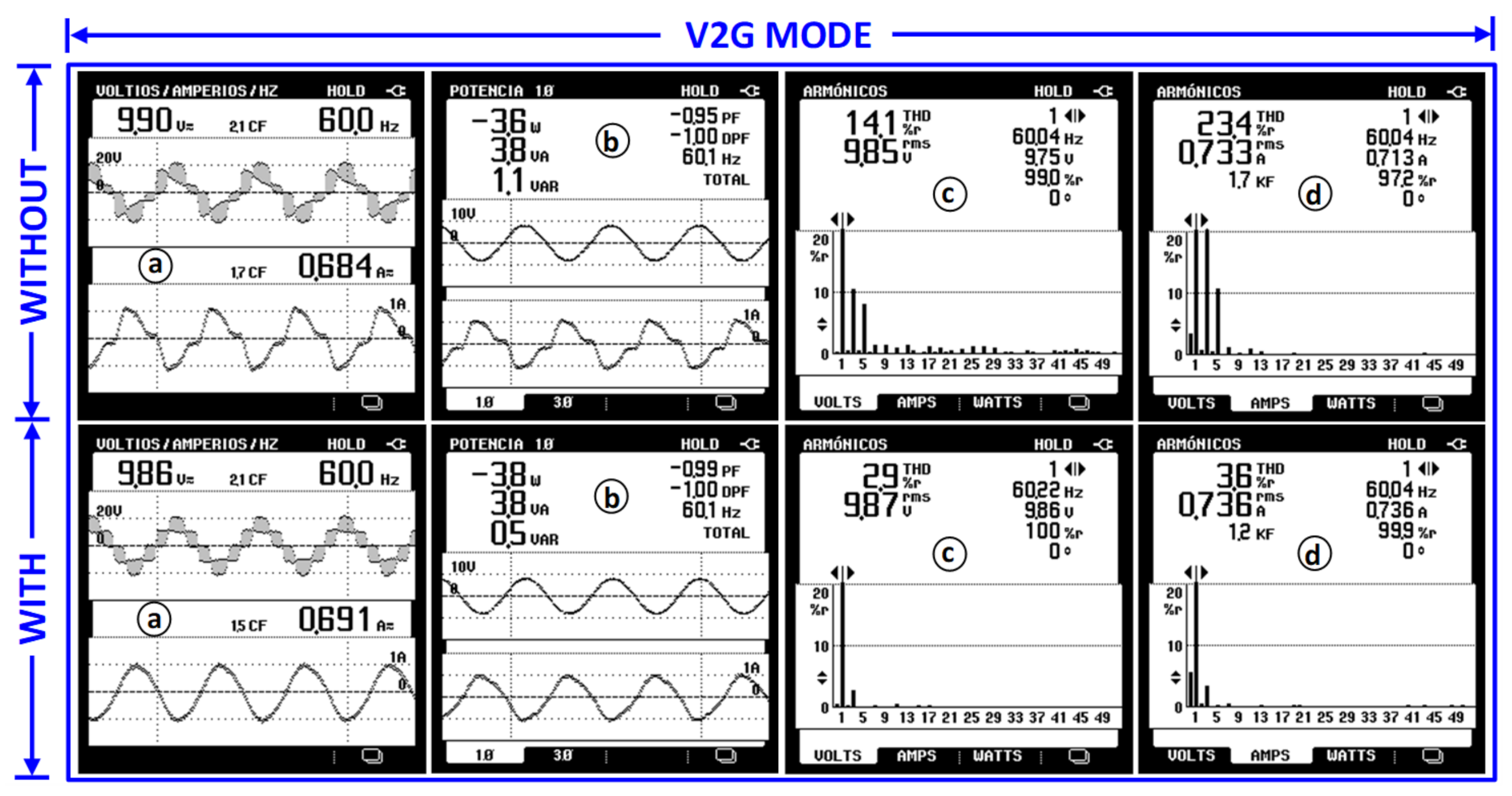
Figure 17 and
Figure 18 show the experimental results obtained from the power quality analysis of the ANPC SPFLBC output voltage
as well as of the grid current
for the V2G and G2V operation modes. In each of these figures, the time signals and their resulting spectra are compared without and with the activation of the proposed voltage balancing strategy. It can be observed how in both V2G and G2V modes, when the voltage balancing strategy is off, the signals
and
are severely distorted, the levels of
are fairly unequal and the power factor is very poor. Once the voltage balancing is on, the following improvement are obtained: (a) In the V2G mode, the THD of
and
reduces from 14.1% and 23.4% to only 2.9% and 3.6%, respectively, whereas in the G2V mode, it reduces from 14.5% and 26.1% to only 1.8% and 3.1%, respectively. (b) In the V2G mode, the reactive power reduces from 1.1 Vars to 0.5 Vars whereas in the G2 V mode, it reduces from 3.5 Vars to only 1.5 Vars. (c) In the V2G mode, the power factor increases from −0.95 to −0.99 whereas in the G2V mode, it increases from 0.93 to 0.99. In general, it is noteworthy that when the voltage balancing is on, the levels of
become symmetric, the harmonic content of
and
fairly reduces, the reactive power on the grid side decreases and the power factor notably improves.
The power losses distribution and the efficiency for the three different single-phase ANPC five-level topologies under study are shown in
Figure 19 and
Table 4, respectively. For ease of comparison, the set of graphs in both V2G and G2V modes has been normalized while the notation of the switches match with the letters A-J used in topologies of
Figure 1. It can be observed that the ANPC-FLC of [
21] with only eight switches is the more efficient with 96.4% in the V2G mode and 95.8% in the G2V mode. In spite of presenting the lower power losses, this topology is inherently uncapable of balancing the voltage of split capacitors because it does not count with redundant vectors for the states that generate an output of half the DC bus voltage.
Unlike [
21], the ANPC-FLC of [
22] having also eight switches is capable of properly balancing the capacitors voltage. Nevertheless, although in this converter the four switches A–D that withstand the full DC bus voltage commutate at low frequency, such topology presents the lower efficiency due to the higher stress in the remaining switches, i.e., G-H in the V2G mode and E-F in the G2V mode. According to
Table 4, its efficiency in the V2G and G2V modes is 93.5% and 94.1%, respectively.
In comparison with [
21,
22], the proposed ANPC-FLBC has two more switches, i.e., a total of ten. However, unlike [
21] it is capable of balancing the capacitors voltage whereas in contrast with [
22], it not only achieves a better efficiency but a lower stress of the switching devices and a more even distribution of the power losses. The efficiency of the proposed topology is 95.0% in the V2G mode and 94.5% in the G2V mode.
6. Discussion
In comparison with the conventional two-level converters, the multilevel converters are characterized for providing a lower distortion voltage signal and achieve it with lower switching frequencies. These are two big advantages in terms of a lower cost and volume of the required output passive filter as well as a switching losses reduction. Thus, with the aim of increasing the efficiency of multilevel converters, the switching frequency must be kept low but not too much because it can deteriorate the fundamental output signal used for control purposes and compromise the performance of the converter application. In the present work, the switching frequency
of the FLBC has been set to 5 kHz in both simulation and experiments. The results shown in
Section 4 and
Section 5 validate the selection of this frequency by obtaining a good control performance and an efficiency even higher than with the topology proposed in [
22]. A summary of the parameters for the proposed grid-tied ANPC SPFLBC is shown in
Table 3. The selection of
is also based on [
24]. This research works deals with a single-phase five-level converter that implements the same multicarrier phase disposition method used in the present paper.
The parameter discrepancies and drifts due to temperature and aging of the inductive and capacitive components in the power system shown in
Figure 3 do not have an influence on the accuracy and performance of the proposed voltage balancing strategy. Nevertheless, the gain and offset of the Hall-effect voltage sensors used for measuring the voltage of the upper and lower capacitors have a significant effect on the voltage balancing. In the same way, the parameter variations due to temperature in the resistors connected to the operational amplifiers in turn contained within the signal conditioning stage that interfaces the Hall-effect voltage sensors with the analog-to-digital converters of the DSP alike affect the voltage balancing.
With the aim of providing accurate voltage measurements of the split capacitors to the voltage balancing control loop, a digital calibration curve that compensates the nonlinearity and gain mismatch from the voltage sensors as well as an automatic routine that digitally removes their initial voltage offsets have been programmed within the DSP. It important to remark that before taking the initial voltage measurements, the split capacitors are first discharged through a resistor. In spite that the experimental results presented in
Section 5 were obtained at various times in different days as well as under different conditions and scenarios, they exhibited repeatability since the initialization routine has been always performed before starting up the ANPC SPFLBC. Thanks to the nonlinearity, gain mismatch and offset compensations carried out on the voltage sensors, the remaining parameters variations undergone by the full power system during the days of tests have been minor and practically unnoticeable.


