Article

Study on the Selection of the Number of Magnetic Poles and the Slot-Pole Combinations in Fractional Slot PMSM Motor with a High Power Density

1
Department of Electrical Engineering, Faculty of Electrical Engineering and Computer Science, VSB-Technical University of Ostrava, Poruba, 708 00 Ostrava, Czech Republic
2
Łukasiewicz Research Network-Institute of Electric Drives and Machines KOMEL, 40-203 Katowice, Poland
*
Authors to whom correspondence should be addressed.
Energies 2022, 15(1), 215; https://doi.org/10.3390/en15010215
Submission received: 23 November 2021 / Revised: 20 December 2021 / Accepted: 22 December 2021 / Published: 29 December 2021

Abstract

:
Fractional slot, PMSM motors with a properly designed electromagnetic circuit allow for obtaining high power density factors (more than 4 kW per 1 kg of total motor weight). The selection of the number of magnetic poles to the specific dimensions and operating conditions of the motor, as well as the number of slots for the selected number of magnetic poles is the subject of the analysis in this article. This issue is extremely important because it affects the mass of the motor, the value of shaft torque, shaft power and the value of rotor losses. The aim of the work is to select solutions with the highest values of power density factor and, at the same time, the lowest values of rotor losses. The object of the study is a fractional slot PMSM motor with an external solid rotor core with surface permanent magnets (SPM). Motor weight is approximately 10 kg, outer diameter is 200 mm and a maximum power is 50 kW at 4800 r/min. The article analyzes the selection of magnetic poles in the range from 2p = 12 to 2p = 24 and various slot-pole combinations for individual magnetic poles. The target function of the objective was achieved and the calculations results were verified on the physical model. The best solutions were 20-pole, 30-slots (highest efficiency and lowest rotor loss) and 24-pole, 27 slots (highest power density).

1. Introduction

High power density electric motors present a significant challenge in the field of electric drives. Their basic feature is a relatively low weight in relation to the shaft power. By using the term “high power density” in this work, we mean motors with a power density factor of 4 kW and more (maximum power) per 1 kg of total motor weight. Additionally, it should be noted that the power density in this analysis is not achieved by a high rotational speed. The maximum rotational speed of the analyzed motors is 4800 r/min. Their application is needed mainly for the aviation, automotive and marine industries, where internal combustion engines are being displaced [1,2,3,4,5,6].
Fractional slot PMSM (Permanent Magnet Synchronous Motor) motors with concentrated windings are an interesting solution that allows to limit the overall dimensions and thus the mass of motor and at the same time are characterized by high power density factor. In addition, these types of motors have such advantages as: shorter length of end winding connections, small cogging torque and small torque ripple [7,8]. A significant problem for this type of machine, is the increased rotor losses due to subharmonics and higher harmonics in the MMF distribution, which can be limited by the appropriate selection of the slot-pole combination. Moreover, the choice of slot-pole combination also significantly influences the obtained value of shaft power and shaft torque. The question then arises how to choose the appropriate slot-pole combination. The aim of this paper is to carry out an analysis that enables the selection of solutions with the highest values of the power density factor and, at the same time, the lowest values of losses in the rotor elements. Much attention has been paid to the influence of the slot-pole combinations on rotor losses, as it is one of the main factors determining the value of these losses. Another key issue analyzed in this paper is the appropriate selection of the number of magnetic poles 2p to the specific dimensions and operating conditions of the motor. Increasing the number of magnetic poles at a constant rotational speed causes an increase in frequency and thus an increase in power losses in the motor. On the other hand, an increase in the number of poles makes it possible to reduce the cross sections of the elements of the electromagnetic circuit, and thus reduce the mass of the motor. The analyzed issues are important for high power density motor, because they affect the mass of the motor, the value of the shaft torque, as well as the value of rotor losses (rotor yoke and permanent magnets) [9,10,11,12,13,14,15,16,17,18,19,20,21].
The object of the study is a fractional slot PMSM motor with an external solid rotor core with surface permanent magnets (SPM). The basic design assumptions for this motor are the weight of approximately 10 kg, the outer diameter not greater than 200 mm, the maximum power of approximately 50 kW and the maximum rotational speed 4800 r/min. It should be noted that motors with high power density operate under high frequency supply conditions, with high magnetic saturation of the magnetic circuit elements and high current loads. For this reason, the basic, but not the only condition for obtaining the appropriate motor power density is the appropriate design of the motor’s electromagnetic circuit.
The article presents a certain method of proceeding that leads to the achievement of the assumed goal function. The analysis was carried out in two stages: analytical and based on FEM calculations. In the analytical analysis, the harmonic distribution of the magnetomotive force MMF was used for the initial pre-selection of solutions. From among the analyzed 25 cases in the range of 2p = 12 to 2p = 24, 12 solutions were selected for further FEM analysis. In the second stage, for each slot-pole combination, a FEM model was developed and calculations were carried out in order to select the best solutions. The results of the calculations were confirmed by the results of laboratory tests for the selected 20-pole, 24-slotcombination for the model of motor.
The selection of the slot-pole combinations in PMSM fractional-slot motors affects many operational parameters and therefore is an issue widely described in the literature. In [22], the authors analyze the effect of the slot-pole combinations on the cogging torque in the motor with concentrated winding. In the publication [23], the purpose of the presented analysis is to determine the correct slot-pole combinations due to fault tolerance in a multi-phase generator with a power of approximately 250 kW. The papers [24,25,26] present an analysis of the influence of the slot-pole combinations on magnetic forces and vibrations in permanent magnet motors. The article [27] describes the influence of slot and pole selection on the shaft voltage in the motor, and the paper [28] concerns the analysis of the slot-pole combinations effect on AC Losses in the winding. None of the above works covers the issues analyzed in this article.
The phenomenon of negative impact on rotor losses due to incorrect selection of the slot-pole combinations is also known from the literature [15,29]. However, these papers focus on the theoretical consideration of the issue without taking into account the target operating conditions and requirements for high power density motors, which significantly determine the specific values of these losses. The conclusions presented in these works do not take into account, for example, the dimensions of magnets (surface, volume) depending on the selected number of motor poles, which is very important for the value of eddy current losses (even while maintaining the theoretically correct slot-pole combinations due to the distribution of the magnetomotive force MMF). The presented conclusions are therefore only general guidelines, but do not provide a complete answer to the objectives set in this paper. Moreover, none of the papers analyze the selection of the number of magnetic poles to specific motor operating conditions.
In [18,20,30], the influence of slot-pole selection was analyzed, but for the IPM (Interior Permanent Magnet) motor with concentrated windings, not SPM motors. In [16], 3-phase, 5-phase and 7-phase machines with a rotor with embedded magnets are analyzed. The publication [17] presents the slot-pole combinations analysis for the reluctance motor. The works [19,31] present an analysis for hybrid excited machines.
The work [32] analyzes the selection of slot-pole combinations for motors with surface permanent magnets (SPM), but not for high power density motors. The number of magnetic poles of the motor analyzed in the study is limited to 2p = 4, 2p = 8, 2p = 10, which in principle does not allow for obtaining high power density factors in the rotational speed range up to n = 5000 r/min. In this article, the analysis concerns high-pole motors, e.g., 2p = 20, which works with high values of the supply frequency (800 Hz). In [32], the motor operating conditions for which the analysis was carried out are not specified, and they significantly affect the rotor yoke losses and permanent magnet losses. Besides, the motor analyzed in the work [32] has a power about 750 W, and in this work about 50 kW (maximum power), so the scale of the problems also in terms of losses in the rotor is completely different.

2. Calculation Model and Operational Conditions of High Power Density Motor

The subject of the analysis is a high-pole, fractional slot, surface permanent magnet synchronous motor with high power density and external solid rotor core. The basic design assumptions for this motor are the weight of approximately 10 kg, the outer diameter not greater than 200 mm, the maximum power of approximately 50 kW and the range of rotational speed 0–4800 r/min.
The illustrative (not to scale with actual dimensions) structure of a 20-pole and 24-slot motor is taken as an example to show the structure of the machine researched in this paper, which is shown in Figure 1. The mathematical model of the motor in d-q axis can be described by the Equations (1)–(5) [33]:
V s d = R s · i s d + d Ψ s d dt ω · Ψ s q
V s q = R s · i s q + d Ψ s q d t + ω · Ψ s d
Ψ s d = ( L 1 + L m ) · i s d + Ψ P M
Ψ s q = ( L 1 + L m ) · i s q
T Ψ = p · Ψ P M · i s q
where:
  • Vsd, Vsqphase voltage d-axis and q-axis,
  • isd, isqphase current d-axis and q-axis,
  • Ψsd, Ψsqflux d-axis and q-axis,
  • ΨPMpermanent magnet flux,
  • Rsphase resistance of stator winding,
  • L1leakage inductance,
  • Lmmagnetizing inductance,
  • ω—electrical angular speed,
  • TΨelectromagnetic torque,
  • p—number of pole pairs.
The purpose of the analysis presented in the article is the appropriate selection of both the number of magnetic poles to the specific operating conditions of the motor and overall dimensions, as well as the selection of the appropriate slot-pole combinations. The main function of the target is to obtain a high power density factor as well as to reduce rotor losses and thus rotor temperature. It should be noted that the assumptions made impose limited design options for the electromagnetic circuit. Assuming that the maximum supply frequency f is 1000 Hz, the maximum number of magnetic poles is then 2p = 24 (960 Hz for 4800 r/min). Moreover, for the analysis to be reliable, the simulations assumed the same operating conditions and certain features common to all analyzed models (Table 1).
NO27 sheets (0.27 mm) was used in the stator core. The solid rotor core is made of S355j2 steel with permanent magnets of the N45SH type attached to it. The permissible operating temperature for this type of magnet is 150 °C.
The motor is powered by a DC source (e.g., battery) through a frequency converter. The nominal value of the DC supply voltage is 350 V. The analysis carried out as part of this study assumes the maximum rotor speed of n = 4800 r/min. In order to ensure comparable operating conditions for each model, it was assumed that for the maximum rotational speed nmax, rated current In and the selected number of phase turns N, the value of the line to line voltage of motor VLL should be 220–240V. The possibility of working with flux weakening is not assumed for the analyzed variants.
The factor determining the rated parameters of the motor is mainly the permissible operating temperature of individual components. For all analyzed models, it was assumed that the cooling system would be identical (liquid cooling), and the permissible rated current density in the winding would be J = 15 A/mm2.
Moreover, it was assumed that the same magnetic materials will be used in the magnetic circuits, and the maximum value of the flux density in individual elements will also be the same.

3. Slot-Pole Combinations—Analytical Analysis

The analysis in this paper was carried out in two stages. In the first stage, an analytical analysis was performed based on the conclusions from the available literature [7,9,10,11,12,15] and developed graphs of MMF harmonic distribution determined for individual slot-pole combinations. The purpose of this analysis is to pre-select the slot-pole combinations, which allows to obtain the assumed target function, including, in particular, high electromagnetic torque and low rotor losses. The analytical analysis was based on the basic coefficients determined from the following Formulas (6)–(14) [34]:
q = Q s 2 p · m
t m = G C D { Q s , p }
t g = G C D { Q s , 2 p }  
α ph = 2 · π · G C D { Q s , p } Q s
α slot = α ph · p G C D { Q s , p }
k g = s i n ( Q s m · t m · α ph 4 ) Q s m · t m · s i n ( α ph 4 )   for   Q s m · t m   is   odd   number
k g = s i n ( Q s 2 · m · t m · α ph 2 ) Q s 2 · m · t m · s i n ( α ph 2 )   for   Q s m · t m   is   even   number
k s = π · p · Y s Q s
k w = k g · k s
where:
  • q—number of slots per pole and phase,
  • Qs—number of stator slots,
  • 2p—number of magnetic poles,
  • p—number of magnetic pole pairs,
  • m—number of winding phases,
  • tm—number of magnetic symmetries,
  • tg—number of geometric symmetries,
  • Ys—winding pitch,
  • αph—angle between adjacent phasors in a star of slots,
  • αslot—angle between adjacent slots in the star of slots,
  • GCD—greatest common divisor,
  • kg—winding group factor for the fundamental harmonic,
  • ks—winding factor for the fundamental harmonic,
  • kw—main winding factor for the fundamental harmonic.
The star of slots has also an important role in the analysis of fractional slot motors. The method of determining the star of slots has been presented in publications [7,34]. Figure 2 shows an example of a slot star for 20-pole, 24-slot motor.
The stator slot numbers have been assigned to the appropriate phasors. The number of the fundamental MMF harmonic hm is calculated from the quotient of the angle between adjacent slots αslot and the angle between adjacent phasors αph. Another way to determine the number of fundamental harmonic hm is to calculate the number of phasors between slots 1 and 2 (subharmonics) and then increase it by the value 1. In the case shown in Figure 2, the number of subharmonics is 4 (slots 6, 11, 4, 9) so by increasing by the value 1, the number of the fundamental MMF harmonic hm is equal 5.
The practical aspect of the analysis is of fundamental importance, therefore the variants of solutions have been narrowed down to those that meet specific motor operating conditions and allowed to obtain the expected parameters. It was found that in order to meet the condition of a high power density factor, the number of magnetic poles should not be lower than 2p = 12. Reducing the number of motor poles increases the cross-sections of the magnetic circuit elements, and thus increases the mass, therefore the variants 2p < 12 are not considered. On the other hand, increasing the number of magnetic poles increases the supply frequency. In this case, the supply frequency f = 1000 Hz was adopted as the limitation. For such assumptions, the frequency of the supply voltage, depending on the number of magnetic poles, is:
  • 2p = 12, f = 480 Hz
  • 2p = 14, f = 560 Hz
  • 2p = 16, f = 640 Hz
  • 2p = 18, f = 720 Hz
  • 2p = 20, f = 800 Hz
  • 2p = 22, f = 880 Hz
  • 2p = 20, f = 960 Hz
The first factor determining the consideration of a given slot-pole combinations in this analysis was the main winding factor kw, which has a significant impact on the value of the obtained electromagnetic torque. For the case where q = 0.5, it is kw = 0.866 and it was assumed that the slot-pole combinations for which the winding factor kw has a lower value will not be considered. In this way, Table 2 presents possible variants of the slot-pole combinations, showing also the amplitude values of individual harmonics Ah1Ah11, and the number of the fundamental harmonic hm.
It is well known that fractional slot motors have an increased content of harmonics and subharmonics of MMF, which significantly affects the rotor eddy current losses. The correct selection of slot-pole combination allows to limit the content of these harmonics, and thus the value of losses. Figure 3 shows the determined distribution of MMF harmonics for the analyzed slot-pole combination, assuming a symmetrical three-phase supply (I = 1, f = 50 Hz) described by Equations (15)–(17). The number and value of amplitude of the fundamental harmonic hm, determined as described on page 6, is marked in Figure 3 with a separate color.
i a ( t ) = I · sin ( ω · t )
i b ( t ) = I · sin ( ω · t + 2 π 3 )
i c ( t ) = I · sin ( ω · t 2 π 3 )
where: I = 1, t = 0.02s, ω = 314.16.
From the presented data in Table 2 and Figure 3 it can be seen that the slot-pole combinations for which the number of stator slots Qs is smaller than the number of magnetic poles 2p are characterized by a large value of subharmonic amplitude, higher than the value of the fundamental harmonic amplitude hm. These solutions were rejected in further analysis due to the expected high values of eddy-current losses in the rotor elements (except for one 2p = 20, Qs = 18, which was to confirm the validity of the above thesis). These are the slot-pole combinations:
  • 2p = 14, Qs = 12
  • 2p = 16, Qs = 15
  • 2p = 20, Qs = 15
  • 2p = 20, Qs = 18
  • 2p = 22, Qs = 18
  • 2p = 22, Qs = 21
  • 2p = 24, Qs = 18
The second group of slot-pole combinations from Table 2 are variants with factor q = 0.5, for which the number of stator slots Qs is greater than the number of magnetic poles 2p. For this slot-pole group, theoretically, the value of rotor losses should be the lowest [9,10], however, the winding factor kw = 0.866 is also lower compared to other slot-pole combinations. This may result in a lower power density factor. This group includes variants of the solution:
  • 2p = 12, Qs = 18
  • 2p = 14, Qs = 21
  • 2p = 16, Qs = 24
  • 2p = 18, Qs = 27
  • 2p = 20, Qs = 30
  • 2p = 22, Qs = 33
  • 2p = 24, Qs = 36
Thus, the last remaining group of slot-pole combinations are the following solution variants:
  • 2p = 14, Qs = 15
  • 2p = 14, Qs = 18
  • 2p = 16, Qs = 18
  • 2p = 16, Qs = 21
  • 2p = 20, Qs = 21
  • 2p = 20, Qs = 24
  • 2p = 20, Qs = 27
  • 2p = 22, Qs = 24
  • 2p = 22, Qs = 27
  • 2p = 22, Qs = 30
  • 2p = 24, Qs = 27
The solutions 2p = 20, Qs = 27, as well as 2p = 22, Qs = 30 were rejected in further analysis due to the lowest value of the winding factor kw, and at the same time a series of subharmonics, although with a small amplitude value.
The solution 2p = 14, Qs = 15 is characterized by a high value of the winding factor kw = 0.951, but due to the relatively high content of subharmonics, high value of the 8th harmonic amplitude and a relatively small number of poles, this solution was also rejected for further analysis as not promising the possibility of obtaining the assumed objective function.

4. Slot-Pole Combinations—FEM Analysis

From the variants presented in the previous analytical analysis, the following variants were adopted for the FEM analysis:
  • 2p = 12, Qs = 18, q = 0.5
  • 2p = 14, Qs = 18, q = 0.429
  • 2p = 16, Qs = 18, q = 0.375
  • 2p = 16, Qs = 21, q = 0.438
  • 2p = 18, Qs = 27, q = 0.5
  • 2p = 20, Qs = 18, q = 0.3
  • 2p = 20, Qs = 21, q = 0.35
  • 2p = 20, Qs = 24, q = 0.4
  • 2p = 20, Qs = 30, q = 0.5
  • 2p = 22, Qs = 24, q = 0.364
  • 2p = 22, Qs = 27, q = 0.409
  • 2p = 24, Qs = 27, q = 0.375
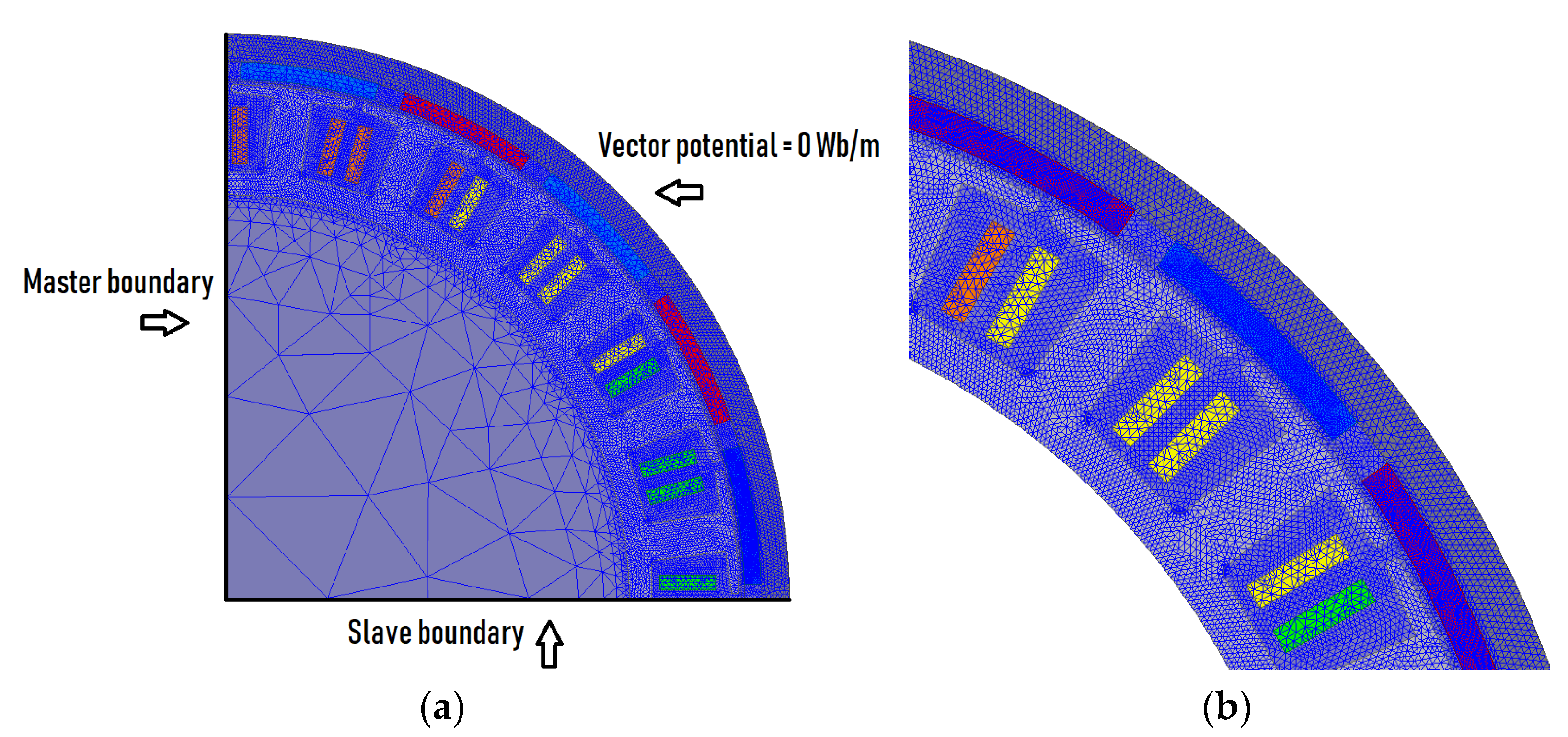
For each of them, FEM models were developed in this stage. From the group of slot-pole combinations with q = 0.5, 3 variants were selected (2p = 12, Qs = 18; 2p = 18, Qs = 27; 2p = 20, Qs = 30) considering that it is sufficient for a comparative statement.
The analysis was performed on the 2-dimensional FEM model of motor using ANSYS Maxwell software. Therefore, the end effect and the axial segmentation of the magnets are not included. The calculations were performed for the one full magnetic symmetry of the given model. The calculation model of the motor for an exemplary combination of slot-pole 2p = 20, Qs = 24, with a finite element mesh is shown in Figure 4. For each developed model, the maximum length of the mesh edge of the elements is:
  • Magnets—0.4 mm,
  • Rotor yoke—1.2 mm,
  • Stator core—0.9 mm,
  • Outer region—0.8 mm,
The analysis was carried out using the time-step solver (transient). In order to eliminate errors in the current waveforms that can be introduced by the simulation, the analysis was performed with a time step equal 2T/200 (depending on the rotational speed of the rotor), where T is the full run period. The time-dependent magnetic equation of motor model is expressed as [36]:
  ×   μ 1   ×   A = J σ A t σ V +   ×   H c
where:
  • A—the magnetic vector potential,
  • J—the source current density,
  • V—the electric vector potential,
  • Hc—coercivity of the permanent magnet,
  • µ—permeability,
  • σ—conductivity.
The divergence-free condition for the magnetic flux density B is ensured by expressing B in terms of the magnetic vector potential A as [36]:
B =   ×   A
Magnetic vector potential distribution A is given by the solution of Laplace’s equation [36]:
2 A = 0
The boundary conditions in the calculation model are defined by the value of the magnetic potential vector A equal to 0, on the outer edge of the rotor core. The master/slave boundary is defined at the symmetry edges of the model. Matching this boundaries allow to take advantage of periodicity in a structure. The field on the master boundary is mapped to the slave boundary.
The aim of the analytical analysis carried out in the first stage was to pre-select the slot-pole combinations, which makes it possible to obtain high operating parameters of the motor and, at the same time, relatively low eddy-current losses in the rotor. The purpose of the FEM analysis is to determine in detail the values of both the basic operating parameters of the motor, as well as power losses.
The parameter obtained in the FEM calculations is the electromagnetic torque TΨ. It should be noted that the value of electromagnetic torque TΨ is ultimately different than the value of the useful shaft torque Tshaft, because the electromagnetic power PΨ calculated in FEM is additionally reduced by rotor losses, mechanical losses and losses in the stator core ΔPFes. A fairly frequent phenomenon found in the literature is the comparison of motor design solutions based on the obtained value of the electromagnetic torque [31,32]. This is not entirely the correct approach, because this torque does not take into account the losses associated with the rotor and stator core. Therefore, in some cases, especially when rotor losses ΔPTr are significant, misleading conclusions may be drawn. In this work, the comparative criterion for the slot-pole combinations is both the shaft torque Tshaft, and the shaft power Pshaft, calculated using the Formulas (21)–(22):
P shaft = P Ψ Δ P Fes Δ P Tr Δ P mech
T shaft = 30 π · n · P shaft
where:
P   Ψ = 2 · π · n 60 · T Ψ
Δ P F e s = P h + P c + P e
P h = K h · B 2 · f
P c = K c · ( B · f ) 2
P e = K e · ( B · f ) 1.5
Δ P Tr =   Δ P PM + Δ P Yr
It is well known that the dominant losses in the rotor elements (rotor yoke and permanent magnets) are eddy-current losses, especially when a solid rotor core is used. In paper [10,11,12,13,14,15] the theory of the eddy-current phenomenon are presented. For the PMSM motor, using FEM model, the total value of rotor losses ΔPTr was calculated as the sum of losses in permanent magnets ΔPPM and losses in the rotor yoke ΔPYr (Equation (28)). Magnet losses ΔPPM were calculated as the sum of the losses in individual magnets within one full magnetic symmetry, multiplied by the number of magnetic symmetries. The stator core losses ΔPFes were calculated using the Formula (24). Mechanical losses ΔPmech were estimated on the basis dimensions of bearing and rotational speed. Additional losses ΔPadd were assumed as 1.5% of the electromagnetic power PΨ. Finally, the efficiency of the motor was determined from the Formula (29):
η = P shaft P in
P in = P Ψ + Δ P Cu + Δ P add
Δ P Cu = 3 · I 2 · R s
Δ P add = 0.015 · P Ψ
Δ P Fes —power losses in laminated stator core,
P h —component of hysteresis losses,
P c —component of eddy-current losses,
P e —component of excess losses,
Kh—hysteresis loss coefficient,
Kc—eddy-current loss coefficient,
Ke—excess loss coefficient.
Δ P Tr —total rotor losses,
Δ P PM —total losses in permanent magnets,
Δ P Yr —total losses in rotor yoke,
Δ P mech —mechanical losses,
Δ P add —additional losses,
Δ P Cu —stator winding Joule losses,
P in —input power,
I —phase RMS current.
Based on the presented model, FEM calculations were carried out for the slot-pole combinations. The results are presented in Table 3 and Table 4. The analysis was carried out for the rotational speed n = 4800 r/min and the current density in the winding, respectively J = 15 A/mm2 (Table 3), as the rated value and J = 30 A/mm2 (Table 4), as the maximum value. The rated value of the current density determines the conditions for the continuous operation of the motor, while the values above 15 A/mm2 relate to transient, temporary states. The power density factor ξ calculated in Table 3 and Table 4 relates to the actual model motor weight of 10.5 kg.

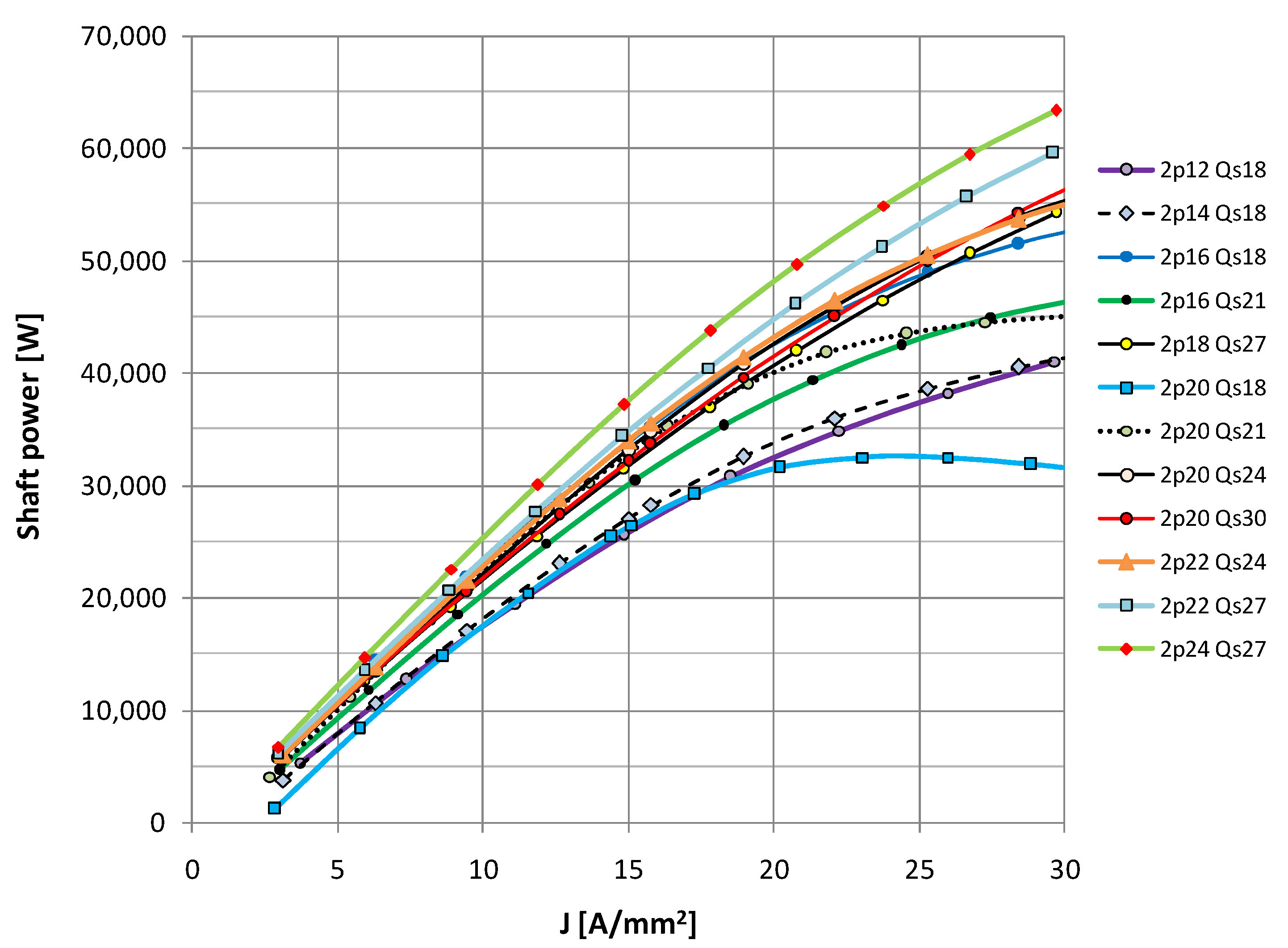
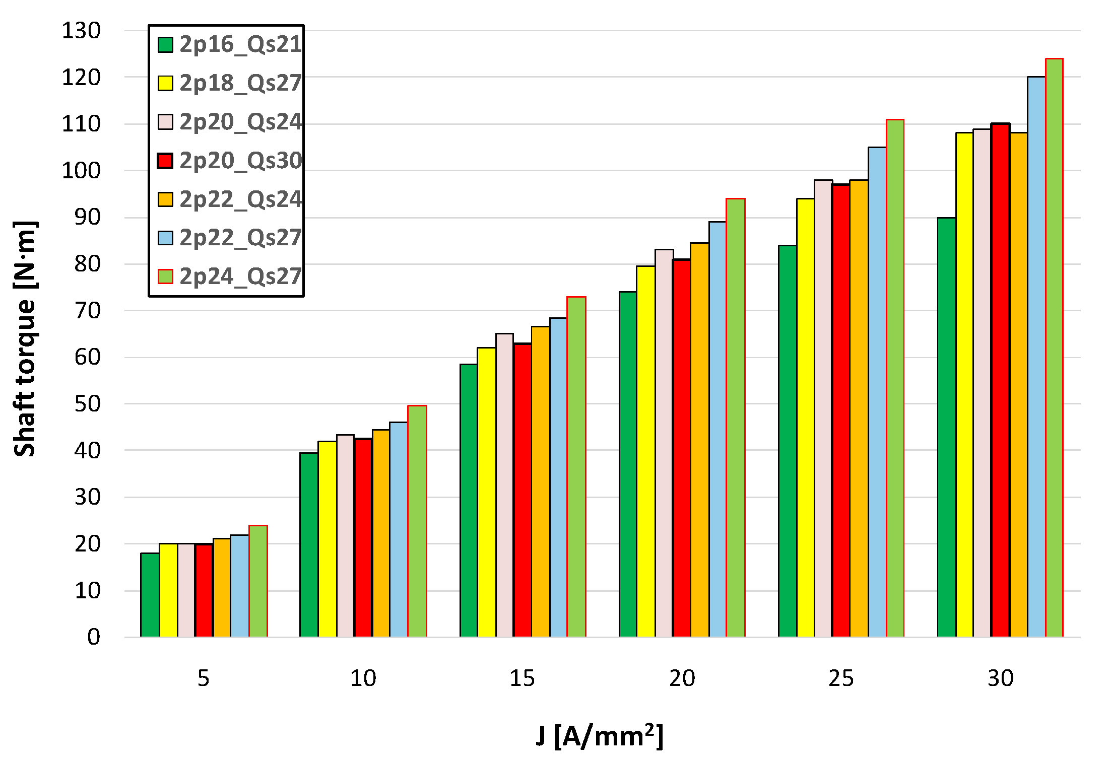
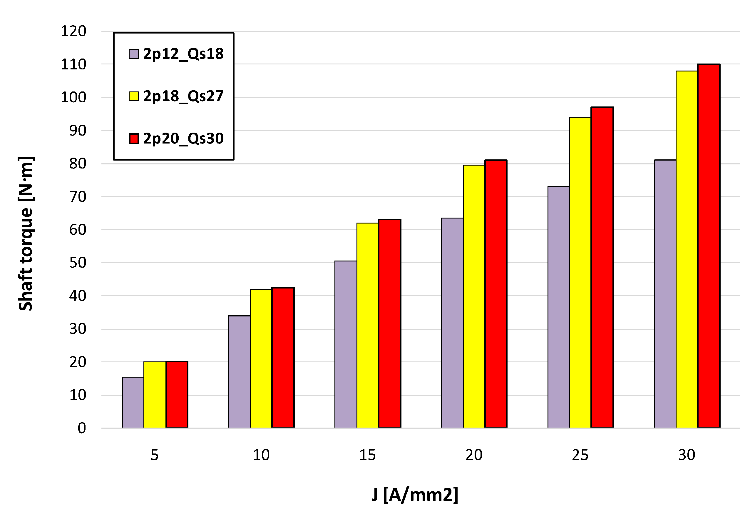
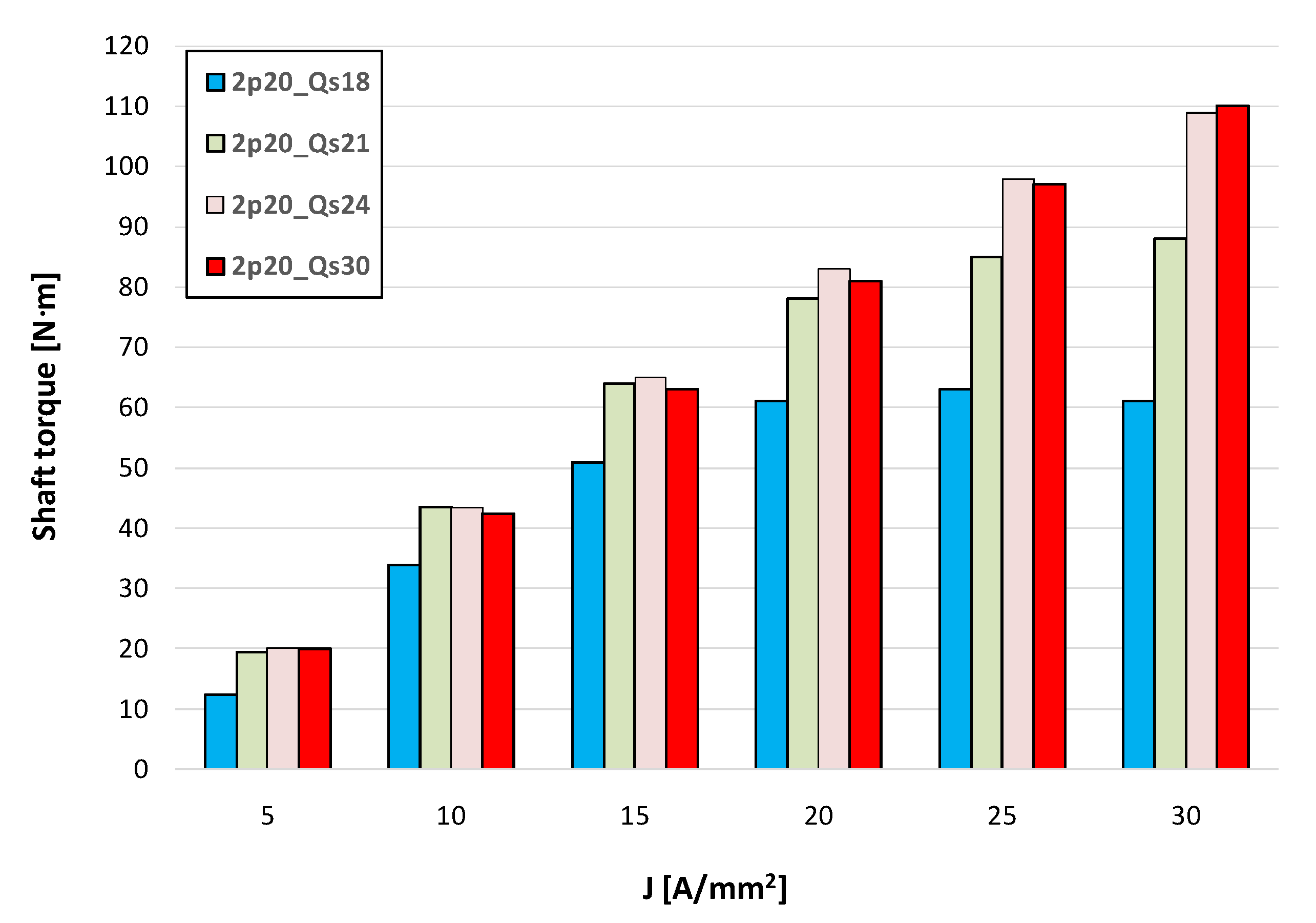
4.1. Shaft Torque and Shaft Power
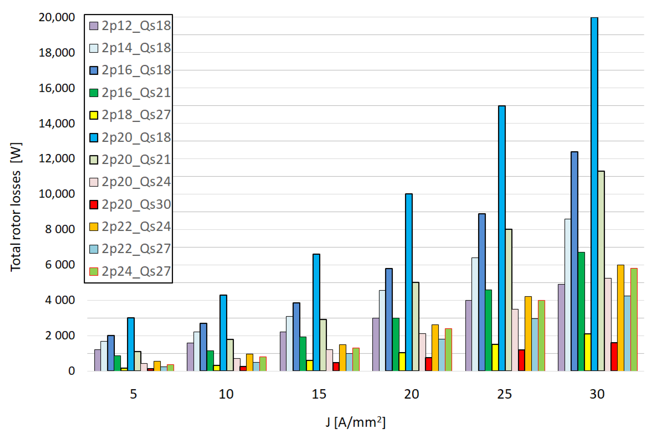
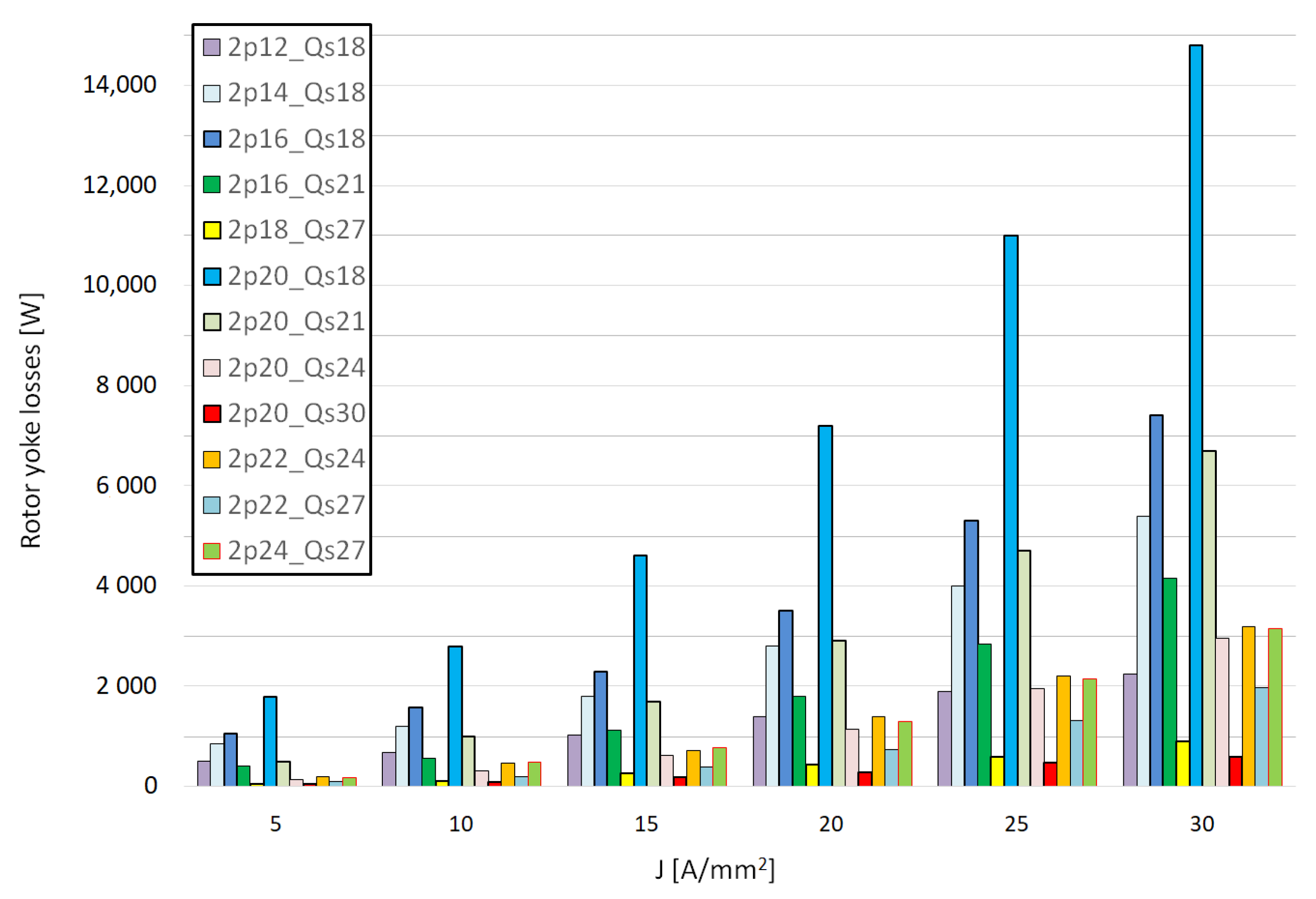
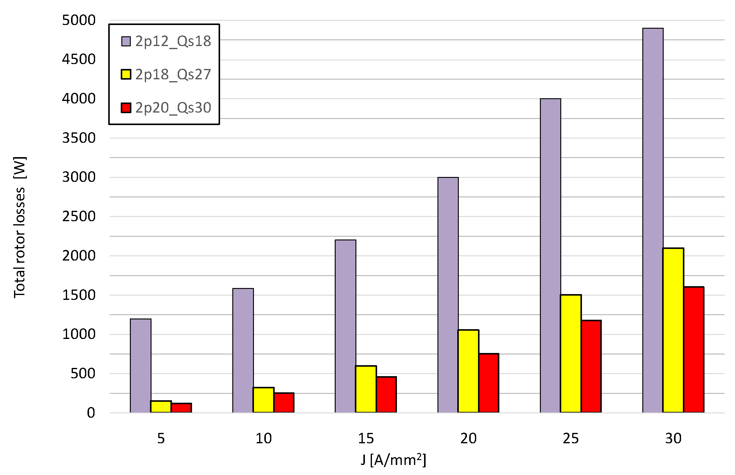
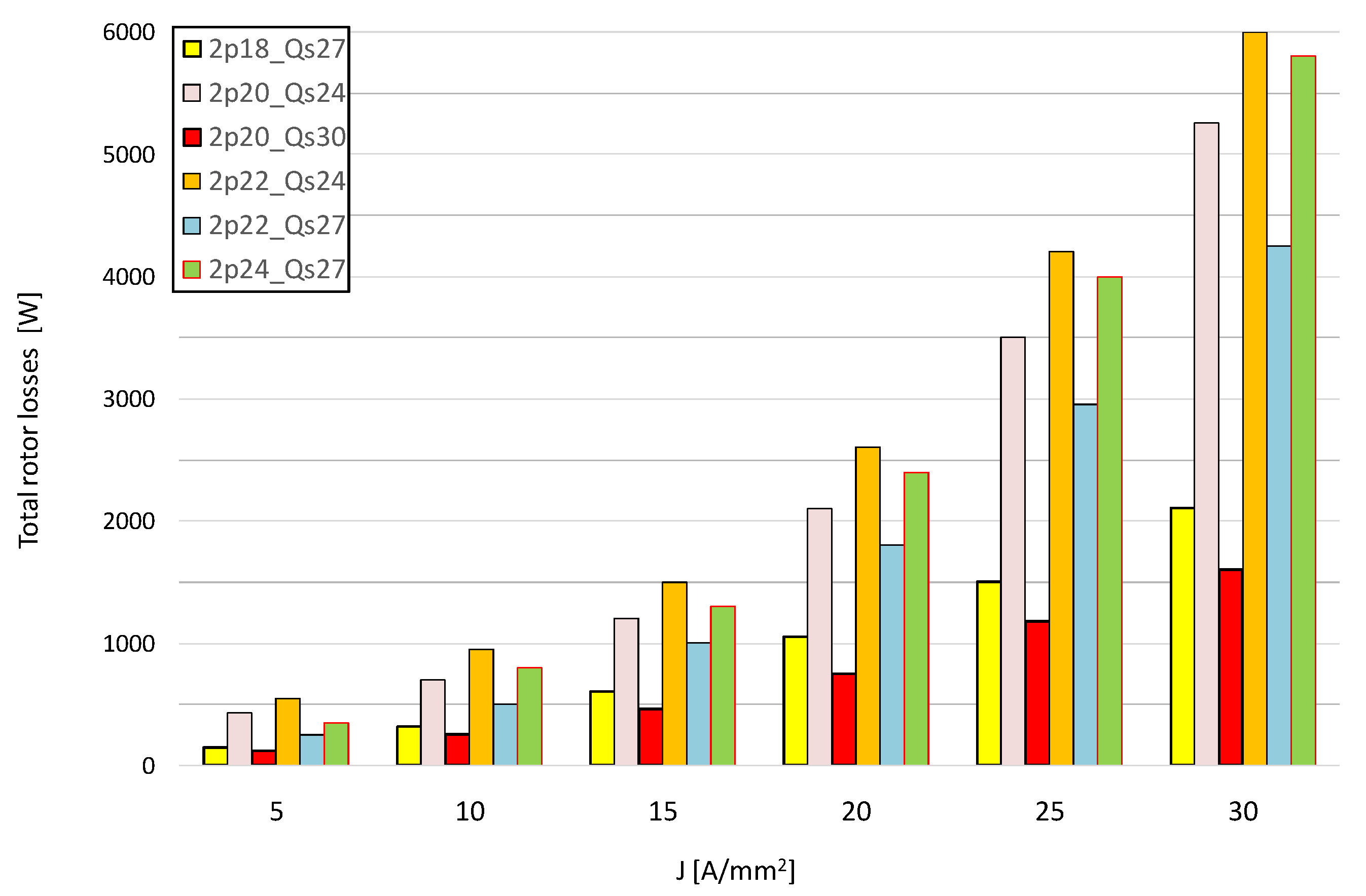
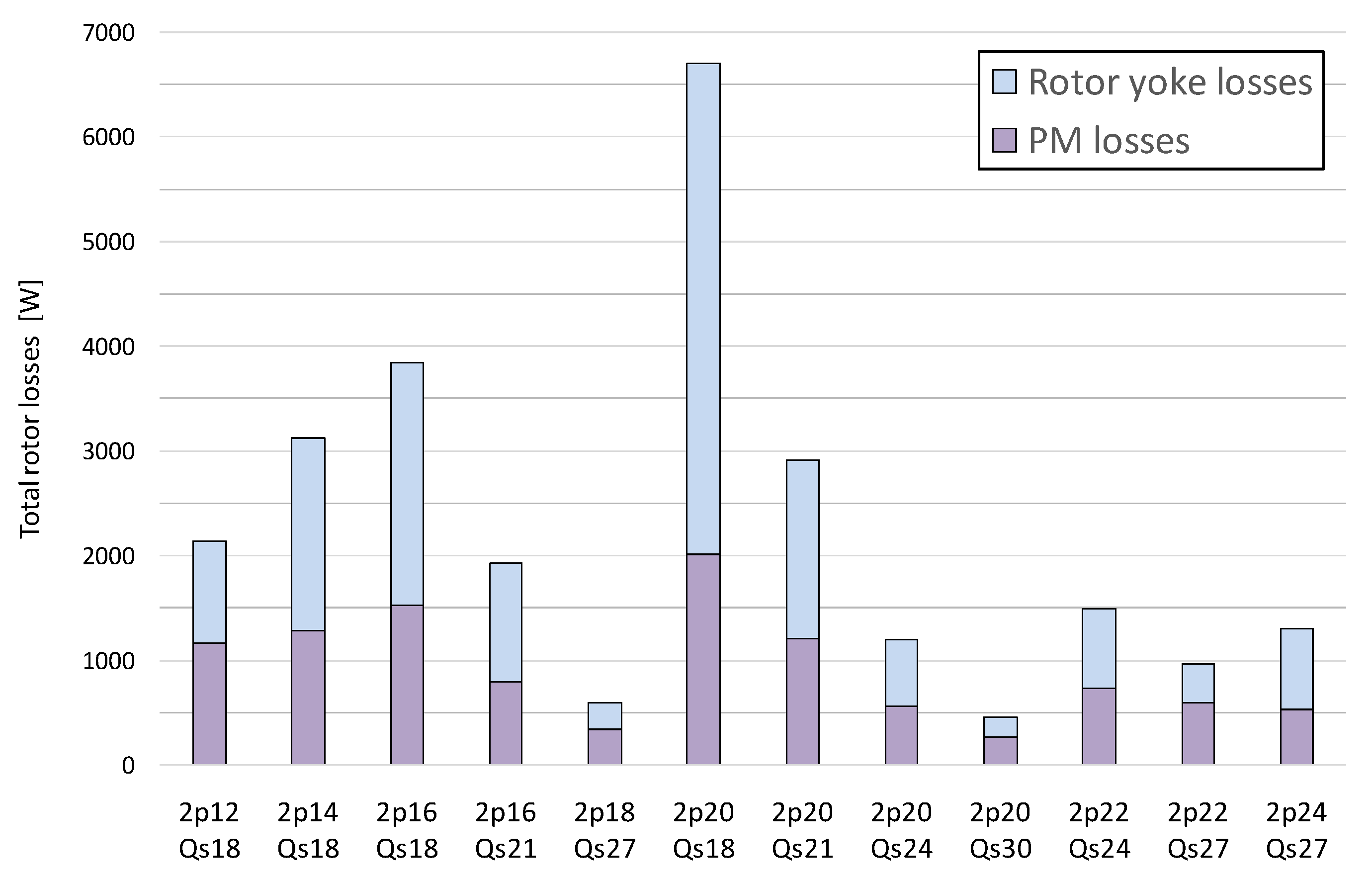
For the slot-pole combinations, the shaft power and shaft torque vs. current density were compared for the assumed maximum rotational speed of n = 4800 r/min. This is very important, because for the maximum rotational speed, both the rotor losses ΔPTr and the stator core losses ΔPFes reach the highest values, which at the same time reduce the torque and power on the shaft in relation to the electromagnetic torque TΨ (Equations (21) and (22)). Comparison of the shaft torque for a lower rotational speed, where the share of these losses is relatively small, could lead to incorrect conclusions. The collective results of the shaft power are shown in Figure 5.
The 24-pole, 27-slot combination is characterized by the highest values of shaft torque and shaft power. The combination of 20-pole, 18-slot has by far the worst parameters. The shaft torque/power value for this combination, especially with high current loads, is almost 50% lower than most other solutions. The reason is the high rotor losses value, especially high losses in the solid rotor core. It is possible to reduce losses in the rotor yoke by using a laminated yoke, however, a solid rotor core has been assumed in this analysis. It simplifies the construction and technology of the rotor.
The main purpose of the analysis was to select solutions with high power density, but also with a low value of rotor losses. Figure 6 shows a comparison of the shaft torque for the slot-pole combinations, which are characterized by the lowest values of rotor losses. The combination 24-pole, 27-slot with a similar winding factor kw and comparable rotor losses as 20-pole, 24-slot and 22-pole, 24-slot, is characterized by a higher value (approximately 10%) of shaft torque.
Figure 7 shows a comparison of the shaft torque for the slot-pole combinations for which q = 0.5. This example shows clearly how important it is to select the number of magnetic poles for specific dimensions and the assumed operating conditions of the motor. The difference in the value of the shaft torque between combinations with the same winding factors kw and MMF harmonic distributions is approximately 30%.
Figure 8 shows a comparison of the shaft torque for the slot-pole combinations with the number of magnetic poles 2p = 20. This example shows the importance of correctly selecting the number of slots to the assumed number of magnetic poles. Despite the lower value of the winding factor kw, the solution 20-pole, 30-slot has a maximum torque value higher by approximately 20–45% compared to the solutions 20-pole, 18-slot and 20-pole, 21-slot.

4.2. Rotor Losses

The aim of the analysis carried out in this paper is to select a slot-pole combination that allows to obtain the maximum motor power density and, at the same time, to have low losses in the rotor. These losses, especially at high power frequencies and high current loads, cause the permanent magnets to heat up, which may lead to their damage.
The collective results of the total rotor losses are shown in Figure 9. Moreover, Figure 10 and Figure 11 show the division of these losses into losses in the rotor yoke and losses in permanent magnets. This separation is important because losses can be limited depending on the source of occurrence e.g., lamination of rotor yoke, magnet segmentation [37]. The calculation model in this paper does not take into account the axial segmentation of the magnets and assumes a solid rotor core.
The lowest value of total rotor losses is characteristic for the combinations of 20-pole, 30-slot and 18-pole, 27-slot. These are solutions for which the coefficient q = 0.5. They are characterized by the lowest content of higher harmonics and the absence of subharmonics in the distribution of the magnetomotive force MMF. However, it should also be noted that q factor is not the only determinant. The combination 12-pole, 18-slot also has the same value of factor q and identical MMF distribution, yet the rotor loss value for this solution is much higher. The comparison is shown in Table 3 and Table 4 by the η k w ratio and is also shown in Figure 12. The reason for this is the much larger (approximately 66%) volume of a single magnet, which results in a higher value of eddy currents. This example shows how important it is to choose not only the slot-pole combinations, but also the number of magnetic poles for the given geometric dimensions and motor operating conditions. By far the worst solution in terms of the value of rotor losses is the combination 20-pole, 18-slot, which was already envisaged at the analytical analysis stage, due to the large subharmonic amplitude, greater than the fundamental harmonic. This is the case whenever the number of slots Qs is smaller than the number of poles 2p. FEM calculations confirmed the correctness of this thesis.
The combinations of 20-pole, 24-slot, 22-pole, 24-slot and 24-pole, 27-slot are also characterized by a relatively low value of rotor losses. These losses are almost twice as high and more than for the case of 20-pole, 30-slot and 18-pole, 27-slot, but still small compared to other solutions. A comparison of total rotor losses for the most advantageous solutions is shown in Figure 13.
Figure 14 shows the division of the rotor’s total losses into losses in the rotor’s yoke and losses in permanent magnets. The diagram applies to the assumed nominal current density in the winding J = 15 A/mm2. It should be noted that the losses in the solid rotor core almost always exceed 50% of the total rotor losses, and in some cases even more than 60%. This is a very significant share of these losses in the total rotor losses. These rotor yoke losses can be limited by the use of a laminated rotor core, however, it complicates the technology of its production.

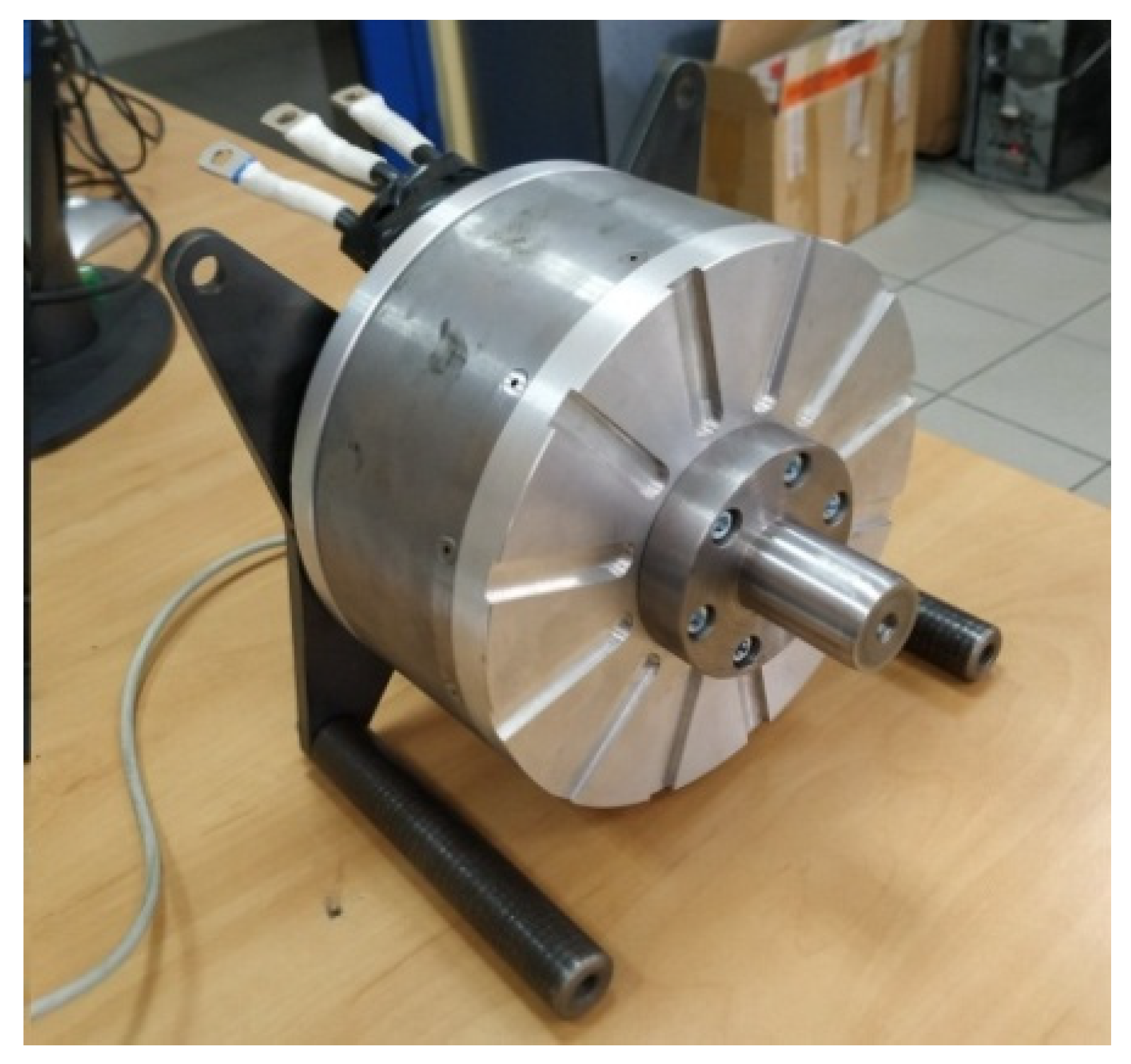
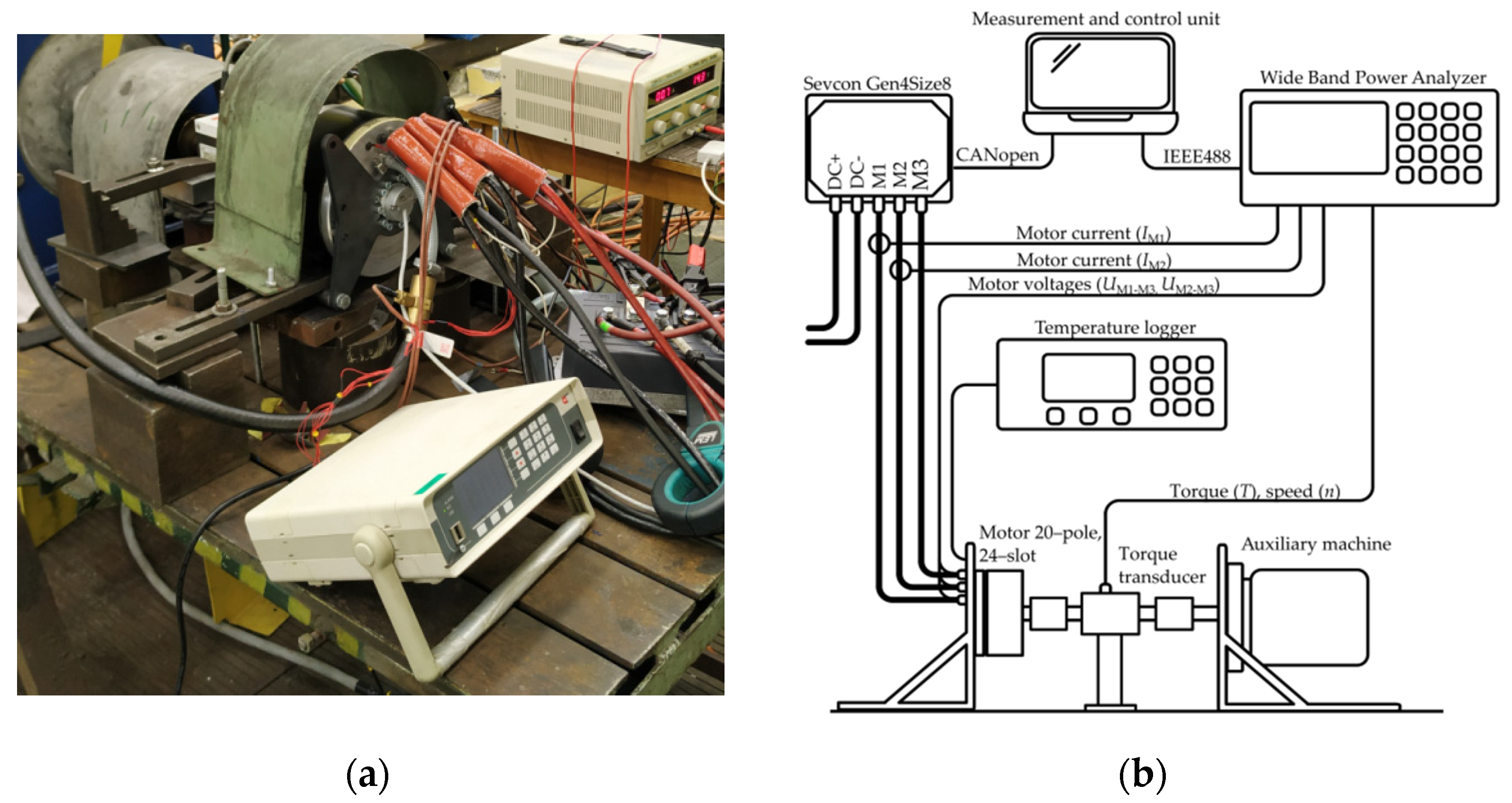
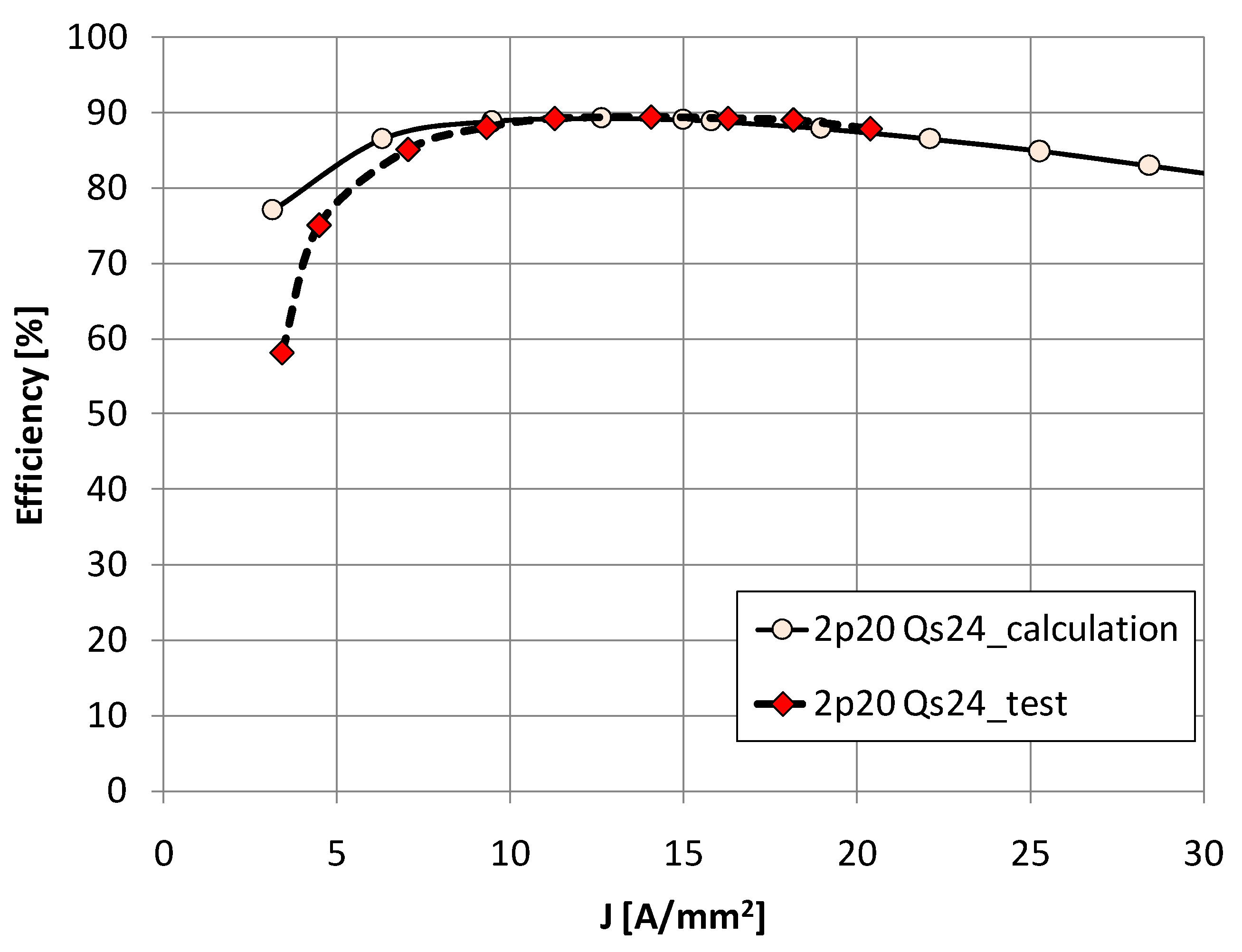
5. Experimental Verification

On the basis of the analysis, the physical model of the motor with 20-pole, 24-slot was made to verify the calculations. This solution was chosen only to verify the calculation results and not because it is the best solution. For a 20-pole, 30-slot combination, rotor losses are smaller at a similar power density factor, but we wanted to verify a solution other than q = 0.5. The solutions with the number of poles 2p = 22 and 2p = 24 despite the favorable parameters were not selected due to the limitations of the available measuring apparatus (measurement possible up to 800 Hz of the fundamental harmonic).
The physical model of the motor is shown in Figure 15. The rotor core is made as solid, while the axial segmentation of the magnets (4 segments) and their skew are provided in order to minimize the cogging torque. This affects both the value of rotor losses and, in the case of a skew, a slight deterioration of the operating parameters. The use of a solid rotor simplifies the production technology and reduces the rotor’s weight due to the lack of additional supporting elements necessary for the laminated core. The total weight of the motor is 10.5 kg.
Figure 16 shows the motor installed on the test stand and the scheme of the measurement system. The motor was powered by a SEVCON inverter. Wide Band Power Analyzer LEM D6000 was used to measure electrical quantities. The shaft torque and rotational speed was measured with a torque meter HBM T20WN 200Nm. The temperature of the windings was read from the Pt100 sensors installed in the winding and recorded using the MPI-CL data acquisition system, while the rotor temperature was read using the Flir E300 thermal imaging camera.
Table 5 shows the measured values of the shaft torque and the power consumed by the motor. Shaft power, efficiency and loss sum ΣΔP were directly determined from these measured quantities. The heating test was carried out for the nominal current density of J = 15 A/mm2 and the maximum rotational speed of n = 4800 r/min. The rotor temperature at the end of the test was Trotor = 130 °C, and the stator winding temperature was also Tstator = 130 °C. The permissible temperatures were therefore not exceeded.
The comparison of the calculated and measured value of the shaft torque as a function of the current density in the winding is shown in Figure 17. Figure 18 shows the comparison of the efficiency characteristics of the computational model and the physical model.
Generally, the obtained results are convergent. The smaller value of the obtained shaft torque in relation to the calculations may result from:
  • the introduced skew of the magnets,
  • a higher actual temperature of the magnets (120 °C) than assumed in the calculations (80 °C),
  • possible control inaccuracies due to incorrectly read encoder signals.

6. Conclusions

The article presents studies on the selection of the number of magnetic poles and the slot-pole combinations for a fractional slot PMSM motor with high power density. This issue is very significant as it affects the obtained shaft power and shaft torque, as well as the rotor losses, which are a significant problem for this type of machine. The aim of this study was to determine the slot-pole combination that allows to obtain the maximum values of the power density factor and the minimum values of rotor losses. Based on the conducted analysis, the assumed goal was achieved.
The article presents a certain method of proceeding that leads to the achievement of the assumed goal function. The analysis was carried out in two stages: analytical an based on FEM calculations. In the analytical analysis, the harmonic distribution of the magnetomotive force MMF was used for the initial pre-selection of solutions. In the second stage, for each slot-pole combination, a FEM model was developed and calculations were carried out in order to select the best solutions. The results of the calculations were confirmed by the results of laboratory tests for the selected 20-pole, 24-slot combination for the model of motor.
  • The following conclusions can be drawn from the analysis carried out in this paper:
  • For fractional-slot motors with high power density, the key issue at the design stage is the correct selection of both the number of magnetic poles to the specific dimensions and operating conditions of the motor, as well as the slot-pole combinations. This choice significantly determines the parameters of the motor and its operating capabilities.
  • For the analyzed motor case (approximately 10 kg, max. 4800 r/min, outer diameter 200 mm, solid rotor core) in terms of the power density factor the best solution is the combination 24-pole, 27-slots, although the power frequency for this case is the highest and amounts to f = 960 Hz. For this slot-pole combination, the obtained power density factor is ξ = 6.0 kW/kg and is much better than the other. Based on the test results for the motor 20-pole, 24-slots and due to the similar values of the calculated total rotor losses for the combination 24-pole, 27-slot, it can be assumed that the rotor temperatures for this configuration will also not exceed the permissible values. However, difficulties in controlling and powering the motor at a frequency of 960 Hz should be emphasized. This can be difficult, especially for high current loads.
  • The best slot-pole combination in terms of efficiency and the lowest rotor losses are 20-pole, 30-slot (q = 0.5). The rotor losses for this solution are 2.6 times smaller in relation to the 20-pole, 24-slot and 2.8 times lower in relation to the 24-pole, 27-slot.
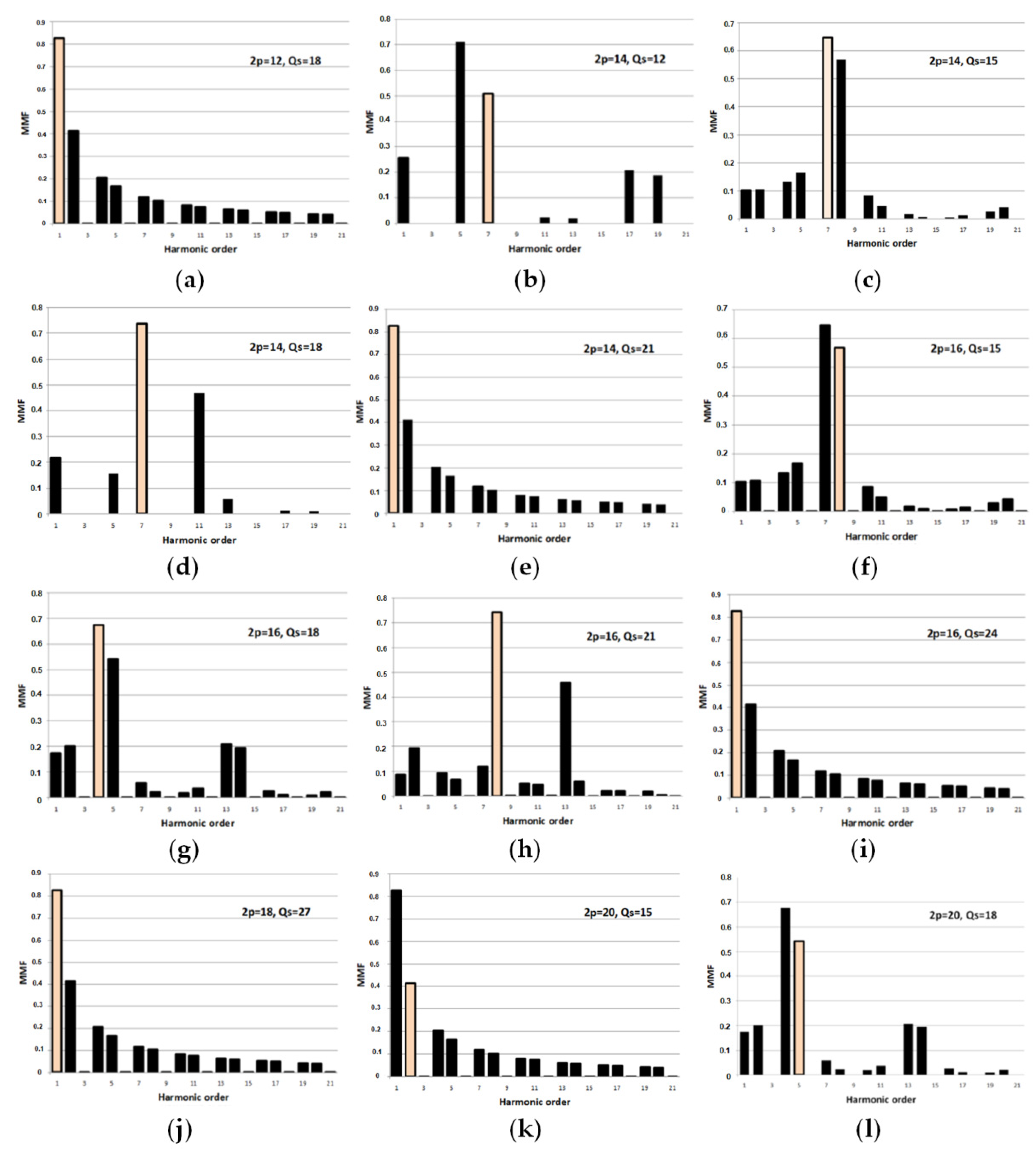
  • In fractional-slot motors, special attention should be paid to the distribution of the magnetomotive force MMF and the winding factor kw for a given slot-pole combinations. These factors largely determine the output parameters of the motor as well as rotor losses. Especially the slot-pole combinations should be avoided, for which there are subharmonics with a large amplitude value in the MMF harmonic distribution. This is the case when the number of stator slots Qs is smaller than the number of magnetic poles 2p.
  • The slot-pole combinations for which the coefficient q = 0.5 (no subharmonics in the MMF distribution) are characterized by the lowest value of rotor losses, provided that the number of magnetic poles of the motor is appropriately selected for its overall dimensions and operating conditions. The magnet losses depend not only on the distribution of the MMF, but also on e.g., the actual dimensions and volumes of the permanent magnets, which may be different for a different number of magnetic poles 2p of the motor.
  • The selection of the number of magnetic poles to the geometrical dimensions and operational conditions affects the value of the output motor parameters and the rotor losses. It should be noted that the target solution cannot be predicted solely on the basis of the theoretically favorable q value and the winding factor kw. This has been shown in Figure 7 and Figure 12, where we observe different values of shaft torque and significantly different values of rotor losses, despite the fact that the solutions have this same q = 0.5 and winding factor kw = 0.866.
  • Comparisons of solutions for slot-pole combinations should be made only on the basis of shaft torque and shaft power, not electromagnetic torque and power. The electromagnetic power in the PMSM motor is reduced by the losses in the stator core and losses in rotor components. In the case of a significant share of these losses in the total losses, it is of key importance, as otherwise the conclusions drawn may be wrong.
  • The study assumes a solid rotor core and no circumferential segmentation of the magnets. The main reason was technological and mechanical considerations. However, these assumptions have a significant impact on the results. Core losses can be limited by using a laminated core, while magnet losses can be limited by circumferential segmentation of the magnets [37]. In the case of a solid rotor core, the share of the rotor yoke losses in the total rotor losses is significant and amounts to approximately 50% or more for most slot-pole combinations.

Author Contributions

T.W.—development of computational models, simulation, designing of electromagnetic circuits, analysis of simulation results, preparation of the article. V.S.—participation in the creation of proposals, editorial article. T.M.—participation in the creation of proposals, editorial article. All authors have read and agreed to the published version of the manuscript.

Funding

This paper was supported by the Student Grant Agency VSB-TUO SGS 2101/SV4201121 financed by the Ministry of Education, Youth and Sports of the Czech Republic.

Institutional Review Board Statement

Not applicable.

Informed Consent Statement

Not applicable.

Data Availability Statement

Not applicable.

Conflicts of Interest

The authors declare no conflict of interest.

References

  1. Ramesh, P.; Lenin, C.N. High Power Density Electrical Machines for Electric VehiclesComprehensive Review Based on Material Technology. IEEE Trans. Magn. 2019, 55, 1–21. [Google Scholar] [CrossRef]
  2. Fulai, G.; Chengning, Z. Oil-cooling method of the permanent magnet synchronous motor for electric vehicle. Energies 2019, 12, 2984. [Google Scholar]
  3. EL-Refaie, A.M.; Alexander, J.P.; Galioto, S.; Reddy, P.B.; Huh, K.K.; de Bock, P.; Shen, X. Advanced High-Power-Density Interior Permanent Magnet Motor for Traction Applications. IEEE Trans. Ind. Appl. 2014, 50, 3235–3248. [Google Scholar] [CrossRef]
  4. Park, H.-J.; Lim, M.-S. Design of High Power Density and High Efficiency Wound-Field Synchronous Motor for Electric Vehicle Traction. IEEE Access 2019, 7, 46677–46685. [Google Scholar] [CrossRef]
  5. Sudha, B.; Anusha, V.; Sachin, S. A review: High power density motors for electric vehicles. Phys. Conf. Ser. 2020, 1706, 1–8. [Google Scholar] [CrossRef]
  6. Wolnik, T.; Dukalski, P.; Będkowski, B.; Jarek, T. Selected aspects of designing motor for direct vehicle wheel drive. Prz. Elektrotechniczny (Electr. Rev.) 2020, 96, 150–153. [Google Scholar] [CrossRef]
  7. Bianchi, N.; Bolognani, S.; Pre, M.D. Magnetic loading of fractional slot three phase PM motors with non overlapped coils. In Proceedings of the IEEE Conference Record of the 2006 IEEE Industry Applications Conference Forty-First IAS Annual Meeting, Tampa, FL, USA, 8–12 October 2006; pp. 35–43. [Google Scholar] [CrossRef]
  8. EL-Refaie, A.M. Fractional-Slot Concentrated-Windings Synchronous Permanent Magnet Machines: Opportunities and Challenges. IEEE Trans. Ind. Electron. 2010, 57, 107–121. [Google Scholar] [CrossRef]
  9. Bianchi, N.; Bolognani, S.; Fomasiero, E. A General Approach to Determine the Rotor Losses in Three-Phase Fractional-Slot PM Machines. In Proceedings of the IEEE International Electric Machines & Drives Conference, Antalya, Turkey, 3–5 May 2007; pp. 634–641. [Google Scholar]
  10. Ishak, D.; Zhu, Z.Q.; Howe, D. Eddy-current loss in the rotor magnets of permanent-magnet brushless machines having a fractional number of slots per pole. IEEE Trans. Magn. 2005, 41, 2462–2469. [Google Scholar] [CrossRef] [Green Version]
  11. Yu, X.; Guoli, L.; Zhe, Q.; Qiubo, Y.; Zhenggen, Z. Research on rotor magnet loss in fractional-slot concentrated-windings permanent magnet motor. In Proceedings of the 2016 IEEE 11th Conference on Industrial Electronics and Applications (ICIEA), Hefei, China, 5–7 June 2016; pp. 1616–1620. [Google Scholar]
  12. Atallah, K.; Howe, D.; Mellor, P.H.; Stone, D.A. Rotor loss in permanent-magnet brushless AC machines. IEEE Trans. Ind. Appl. 2000, 36, 1612–1618. [Google Scholar]
  13. Sang-Yub, L.; Hyun-Kyo, J. Eddy current loss analysis in the rotor of permanent magnet traction motor with high power density. In Proceedings of the 2012 IEEE Vehicle Power and Propulsion Conference (VPPC), Seoul, Korea, 9–12 October 2012; pp. 210–214. [Google Scholar]
  14. Toda, H.; Xia, Z.; Wang, J.; Atallah, K.; Howe, D. Rotor Eddy-Current Loss in Permanent Magnet Brushless Machines. IEEE Trans. Magn. 2004, 40, 2104–2106. [Google Scholar] [CrossRef] [Green Version]
  15. Nakano, M.; Kometani, H.; Kawamura, M. A study on eddy-current losses in rotors of surface permanent-magnet synchronous machines. IEEE Trans. Ind. Appl. 2006, 42, 429–435. [Google Scholar] [CrossRef]
  16. Aslan, B.; Semail, E.; Korecki, J.; Legranger, J. Slot/pole combinations choice for concentrated multiphase machines dedicated to mild-hybrid applications. In Proceedings of the IECON 2011—37th Annual Conference of the IEEE Industrial Electronics Society, Melbourne, Australia, 7–10 November 2011; pp. 3698–3703. [Google Scholar]
  17. Salah, A.; Elnour, M.; Elnail, K. Investigation on influence the slot/pole combinations on the torque performance for synchronous reluctance machine with distributed and concentrated windings. Phys. Conf. Ser. 2020, 1601, 1–7. [Google Scholar] [CrossRef]
  18. Goss, J.; Staton, D.; Wrobel, R.; Mellor, P. Brushless AC interior-permanent magnet motor design: Comparison of slot/pole combinations and distributed vs. concentrated windings. In Proceedings of the 2013 IEEE Energy Conversion Congress and Exposition, Denver, CO, USA, 15–19 September 2013; pp. 1213–1219. [Google Scholar]
  19. Sulaiman, E.; Ahmad, M.Z.; Haron, Z.A.; Kosaka, T. Design Studies and Performance of HEFSM with Various SlotPole Combinations for HEV Applications. In Proceedings of the 2012 IEEE International Conference on Power and Energy (PE Con), Kota Kinabalu, Malaysia, 2–5 December 2012; pp. 424–429. [Google Scholar]
  20. Fatemi, A.; Nehl, T.; Yang, X.; Hao, L.; Gopalakrishnan, S.; Omekanda, A.; Namuduri, C. Design Optimization of an Electric Machine for a 48V Hybrid Vehicle with Comparison of Rotor Technologies and Pole-Slot Combinations. IEEE Trans. Ind. Appl. 2020, 56, 4609–4622. [Google Scholar] [CrossRef]
  21. Dukalski, P.; Krok, R. Selected Aspects of Decreasing Weight of Motor Dedicated to Wheel Hub Assembly by Increasing Number of Magnetic Poles. Energies 2021, 14, 917. [Google Scholar] [CrossRef]
  22. Hwang, C.C.; Wu, M.H.; Cheng, S.P. Influence of pole and slot combinations on cogging torque in fractional slot PM motors. J. Magn. Magn. Mater. 2006, 304, e430–e432. [Google Scholar] [CrossRef]
  23. Mitcham, A.J.; Antonopoulos, G.; Cullen, J.J.A. Favourable slot and pole number combinations for fault-tolerant PM machines. IEE Proc-Electr. Power Appl. 2004, 151, 520–525. [Google Scholar] [CrossRef]
  24. Valavi, M.; Nysveen, A.; Nilssen, R.; Lorenz, R.D.; Rolvag, T. Influence of Pole and Slot Combinations on Magnetic Forces and Vibration in Low-Speed PM Wind Generators. IEEE Trans. Magn. 2014, 50, 1–11. [Google Scholar] [CrossRef]
  25. Lin, F.; Zuo, S.G.; Wu, X.D. Electromagnetic vibration and noise analysis of permanent magnet synchronous motor with different slot-pole combinations. IET Electr. Power Appl. 2016, 10, 900–908. [Google Scholar] [CrossRef]
  26. Zhu, Z.Q.; Mohd Jamil, M.L.; Wu, L.J. Influence of Slot and Pole Number Combinations on Unbalanced Magnetic Force in PM Machines With Diametrically Asymmetric Windings. IEEE Trans. Ind. Appl. 2012, 49, 19–30. [Google Scholar] [CrossRef]
  27. Peng, B.; Wang, X.; Zhao, W.; Ren, J. Study on Shaft Voltage in Fractional Slot Permanent Magnet Machine With Different Pole and Slot Number Combinations. IEEE Trans. Magn. 2019, 55, 1–5. [Google Scholar] [CrossRef]
  28. Park, S.-H.; Lee, E.-C.; Lee, G.-J.; Kwon, S.-O.; Lim, M.-S. Effect of Pole and Slot Combination on the AC Joule Loss of Outer-Rotor Permanent Magnet Synchronous Motor Using a High Fill Factor Machined Coil. Energies 2021, 14, 3037. [Google Scholar] [CrossRef]
  29. Wang, J.; Patel, V.; Wang, W. Fractional-Slot Permanent Magnet Brushless Machines with Low Space Harmonic Contents. IEEE Trans. Magn. 2014, 50, 1–9. [Google Scholar] [CrossRef]
  30. Zhang, H.; Wallmark, O. Limitations and Constraints of Eddy-Current Loss Models for Interior Permanent-Magnet Motors with Fractional-Slot Concentrated Windings. Energies 2017, 10, 379. [Google Scholar] [CrossRef] [Green Version]
  31. Zheng, M.; Zhu, Z.Q.; Cai, S.; Li, H.Y.; Liu, Y. Influence of Stator and Rotor Pole Number Combinations on the Electromagnetic Performance of Stator Slot-Opening PM Hybrid-Excited Machine. IEEE Trans. Magn. 2019, 55, 1–10. [Google Scholar] [CrossRef]
  32. Guo, L.; Wang, H. Research on Stator Slot and Rotor Pole Combination and Pole Arc Coefficient in a Surface-Mounted Permanent Magnet Machine by the Finite Element Method. Energies 2021, 12, 26. [Google Scholar] [CrossRef]
  33. Wilamowski, B.M.; Irwin, J.D. Power Electronics and Motor Drives, 2nd ed.; CRC Press Taylor & Francis Group: Boca Raton, FL, USA, 2011. [Google Scholar]
  34. Bianchi, N.; Pre, M.D. Use of the star of slots in designing fractional-slot single-layer synchronous motors. IEE Proc. Electr. Power Appl. 2006, 153, 459–466. [Google Scholar] [CrossRef]
  35. Wolnik, T.; Styskala, V.; Hrbac, R.; Lyaschenko, A.M. The Problem of Rotor Eddy-Current Losses in A Permanent Magnet Motor with High Power Density. In Proceedings of the International Conference on Intelligent Information Technologies for Industry IITI2021, Sochi, Russia, 30 September–4 October 2021; pp. 501–512. [Google Scholar]
  36. Marriott, L.W.; Griner, G.C. Induction Motor Modeling Using Coupled Magnetic Field and Electrical Circuit Equations. In Proceedings of the International Compressor Engineering Conference, Tippecanoe, IN, USA; 1992. Available online: https://books.google.com.hk/books/about/Proceedings_of_the_International_Compres.html?id=Z71ZAAAAYAAJ&redir_esc=y (accessed on 21 December 2021).
  37. Aslan, B.; Semail, E.; Legranger, J. General Analytical Model of Magnet Average Eddy-Current Volume Losses for Comparison of Multiphase PM Machines With Concentrated Winding. IEEE Trans. Energy Convers. 2014, 29, 72–83. [Google Scholar] [CrossRef] [Green Version]
Figure 1. Illustrative structure of a 20-pole, 24-slot motor under analysis.
Energies 15 00215 g001
Figure 2. An example of a designated star of slots for structure of a 20-pole, 24-slot motor [35].
Energies 15 00215 g002
Figure 3. Harmonic distribution of the MMF for the analyzed slot-pole combinations (color marks the fundamental harmonic) (a) 2p = 12, Qs = 18; (b) 2p = 14, Qs = 12; (c) 2p = 14, Qs = 15; (d) 2p = 14, Qs = 18; (e) 2p = 14, Qs = 21; (f) 2p = 16, Qs = 15; (g) 2p = 16, Qs = 18; (h) 2p = 16, Qs = 21; (i) 2p = 16, Qs = 24; (j) 2p = 18, Qs = 27; (k) 2p = 20, Qs = 15; (l) 2p = 20, Qs = 18; (m) 2p = 20, Qs = 21; (n) 2p = 20, Qs = 24; (o) 2p = 20, Qs = 27; (p) 2p = 20, Qs = 30; (q) 2p = 22, Qs = 18; (r) 2p = 22, Qs = 21; (s) 2p = 22, Qs = 24; (t) 2p = 22, Qs = 27; (u) 2p = 22, Qs = 30; (v) 2p = 22, Qs = 33; (w) 2p = 24, Qs = 18; (x) 2p = 24, Qs = 27; (y) 2p = 24, Qs = 36.
Energies 15 00215 g003aEnergies 15 00215 g003b
Figure 4. FEM model of the motor for 20-pole, 24-slots (a) one full magnetic symmetry; (b) fragment of the model with an enlarged finite element mesh.
Energies 15 00215 g004
Figure 5. Shaft power as a function of current density J for the rotational speed n = 4800 r/min for individual slot-pole combinations.
Energies 15 00215 g005
Figure 6. Comparison of the shaft torque vs. current densities J for various slot-pole combinations with the lowest value of rotor losses (n = 4800 r/min).
Energies 15 00215 g006
Figure 7. Comparison of the shaft torque vs. current densities J for various slot-pole combinations with q = 0.5 (n = 4800 r/min).
Energies 15 00215 g007
Figure 8. Comparison of the shaft torque vs. current densities J for various slot-pole combinations with 2p = 20 (f = 800 Hz, n = 4800 r/min).
Energies 15 00215 g008
Figure 9. Total rotor losses as a function of current density J for the rotational speed n = 4800 r/min for individual slot-pole combinations.
Energies 15 00215 g009
Figure 10. Rotor yoke losses as a function of current density J for the rotational speed n = 4800 r/min for individual slot-pole combinations.
Energies 15 00215 g010
Figure 11. Permanent magnet losses as a function of current density J for the rotational speed n = 4800 r/min for individual slot-pole combinations.
Energies 15 00215 g011
Figure 12. Comparison of the total rotor losses vs. current densities J for various slot-pole combinations with q = 0.5 (n = 4800 r/min).
Energies 15 00215 g012
Figure 13. Comparison of total rotor losses vs. current densities J for various slot-pole combinations with relatively smallest rotor losses and at the same time the highest shaft torque values.
Energies 15 00215 g013
Figure 14. Share of losses in the rotor’s yoke and permanent magnets in the total rotor losses for n = 4800 r/min, J = 15 A/mm2.
Energies 15 00215 g014
Figure 15. Physical model of the motor 20-pole, 24-slot.
Energies 15 00215 g015
Figure 16. (a) Physical model of the motor on the test stand; (b) scheme of the measuring system.
Energies 15 00215 g016
Figure 17. Comparison of calculations and lab test of shaft torque for 20-pole, 24-slot motor (n = 4800 r/min).
Energies 15 00215 g017
Figure 18. Comparison of calculations and lab test of efficiency for 20-pole, 24-slot motor (n = 4800 r/min).
Energies 15 00215 g018
Table 1. Common data for the analyzed motor models.
Parameter
DC supply voltage (V)350
Rotational speed (r/min)4800
Line to line voltage of motor (for 4800 r/min, I = nom.) (V)220–240 V
Rated current density (A/mm2)15
Phase advance angle0
Flux weakingnone
Outer diameter of rotor core (mm)200
Length of core (mm)50
Phase number3
Air gap length (mm)1
Thickness of PM (mm)3
Pole arc coefficient0.833
The slot opening width (mm)1.8
The slot opening height (mm)1.3
Winding temperature (°C)120
PM temperature (°C)80
Flux density in the stator teeth (T)2.0
Flux density in the stator yoke (T)1.7
Flux density in the rotor yoke (T)1.85–1.9
Rotor yoke material typeS355j2
Stator core material typeNO27, 0.27 mm
Type of magnetsN45SH
Table 2. Data and coefficients for the initially considered slot-pole combinations (color marks the fundamental harmonic).
2pQsqkwtmtghmAh1Ah2Ah3Ah4Ah5Ah6Ah7Ah8Ah9Ah10Ah11
12180.50.8666610.830.4100.210.1700.120.100.080.08
14120.2860.9331270.260000.7100.510000.02
14150.3570.9511170.10.1100.130.1600.650.5700.080.05
14180.4290.9021270.220000.1600.740000.47
14210.50.8667710.830.4100.210.1700.120.100.080.08
16150.3130.9511180.10.1100.130.1600.650.5700.080.05
16180.3750.9452240.170.200.680.5400.060.0200.020.04
16210.4380.891180.090.1900.090.0700.120.7400.050.04
16240.50.8668810.830.4100.210.1700.120.100.080.08
18270.50.8669910.830.4100.210.1700.120.100.080.08
20150.250.8665520.830.4100.210.1700.120.100.080.08
20180.300.9452250.170.2000.680.5400.060.0200.020.04
20210.350.95311100.070.0700.080.0900.120.1500.640.58
20240.400.9332450.260000.7100.510000.02
20270.450.87711100.060.0900.190.0800.050.0600.750.1
20300.500.866101010.830.4100.210.1700.120.100.080.08
22180.2730.90212110.220000.1600.740000.47
22210.3180.95311110.070.0700.080.0900.120.1500.640.58
22240.3640.94912110.130000.1500.180000.66
22270.4090.91511110.190.0700.140.0500.060.0700.050.72
22300.4550.87412110.110000.1900.090000.76
22330.50.866111110.830.4100.210.1700.120.100.080.08
24180.250.8666620.830.4100.210.1700.120.100.080.08
24270.3750.9453340.170.200.680.5400.060.0200.020.04
24360.50.866121210.830.4100.210.1700.120.100.080.08
Table 3. FEM calculation results for slot-pole combinations for the rotational speed n = 4800 r/min and the current density in the winding J = 15 A/mm2.
Slot-PoleΔPCuΔPFeΔPYrΔPPMΔPTrΔPaddΔPmechPshaftTshaftηξkw η k w  
WWWWWWWkWN·m%kW/kg
2p = 12, Qs = 1812833879781164214242526025.550.885.0%2.40.8660.98
2p = 14, Qs = 18130858918351287312246426027.052.882.2%2.60.9020.91
2p = 16, Qs = 181308131623101533384358726033.767.182.2%3.20.9450.87
2p = 16, Qs = 21133311421125801192650626030.460.585.5%2.90.8900.96
2p = 18, Qs = 271110111726034260250126031.462.589.8%3.00.8661.04
2p = 20, Qs = 181330200546932015670853226026.552.671.0%2.50.9450.75
2p = 20, Qs = 211289148017061214292056326032.965.483.5%3.10.9530.88
2p = 20, Qs = 241170923635567120253326033.266.089.0%3.20.9330.95
2p = 20, Qs = 301091126319127346451226032.163.990.0%3.10.8661.04
2p = 22, Qs = 2411701052762740150255126033.967.588.2%3.20.9490.93
2p = 22, Qs = 271109114438759798455126034.368.389.5%3.30.9150.98
2p = 24, Qs = 2711161660774533130760626037.274.088.3%3.50.9450.93
Table 4. FEM calculation results for slot-pole combinations for the rotational speed n = 4800 r/min and the current density in the winding J = 30 A/mm2.
Slot-PoleΔPCuΔPFeΔPYrΔPPMΔPTrΔPaddΔPmechPshaftTshaftηξkw η k w  
WWWWWWWkWN·m%kW/kg
2p = 12, Qs = 18513067022752616489170226041.081.677.9%3.90.8660.90
2p = 14, Qs = 185231112853243227855176826041.382.172.1%3.90.9020.80
2p = 16, Qs = 18523122867374504412,418101226052.5104.471.2%5.00.9450.75
2p = 16, Qs = 215332190141612564672583126046.692.675.6%4.40.8900.85
2p = 18, Qs = 27444015048521191204387126054.2107.985.6%5.20.8660.99
2p = 20, Qs = 185318360314,875523920,11483126031.462.551.0%3.00.9450.54
2p = 20, Qs = 21512427526639467011,30989126045.189.668.9%4.30.9530.72
2p = 20, Qs = 244679109529332280521392926055.4110.182.0%5.30.9330.88
2p = 20, Qs = 3043641618620979159989726056.3112.186.6%5.40.8661.00
2p = 22, Qs = 244679129033382884622294226055.0109.480.4%5.20.9490.85
2p = 22, Qs = 274437161119092266417598526059.6118.683.9%5.70.9150.92
2p = 24, Qs = 2744642 626308626045690107926063.4126.181.8%6.00.9450.87
Table 5. The results of tests bench of motor 20-pole, 24-slot for n = 4800 r/min.
JPinPshaftTshaftΣΔPη
A/mm2kWkWN·mkW%
3.44.62.75.42.058.1
4.58.36.212.32.175.0
7.115.212.925.62.385.1
9.420.918.436.62.588.1
11.425.522.845.42.789.3
14.332.328.957.43.489.5
16.637.133.165.94.089.3
18.540.936.472.54.589.0
20.846.240.680.85.687.9
Publisher’s Note: MDPI stays neutral with regard to jurisdictional claims in published maps and institutional affiliations.

