Article

Cooling Cyclic Air of Marine Engine with Water-Fuel Emulsion Combustion by Exhaust Heat Recovery Chiller †

1
Machinebuilding Institute, Admiral Makarov National University of Shipbuilding, Heroes of Ukraine Avenue 9, 54025 Mykolayiv, Ukraine
2
Department of Building Physics and Renewable Energy, Kielce University of Technology, Aleja Tysiąclecia Państwa Polskiego, 7, 25-314 Kielce, Poland
*
Authors to whom correspondence should be addressed.
This paper is an extended version of our paper published in 2021 MPSU-2021, E3S Web of Conferences 323, 00031.
Energies 2022, 15(1), 248; https://doi.org/10.3390/en15010248
Submission received: 1 December 2021 / Revised: 22 December 2021 / Accepted: 27 December 2021 / Published: 30 December 2021
(This article belongs to the Special Issue Computational Thermal, Energy, and Environmental Engineering)

Abstract

:
The fuel efficiency of marine diesel engine as any combustion engine falls with raising the temperature of air at the suction of its turbocharger. Therefore, cooling the engine turbocharger intake air by recovering exhaust gas heat to refrigeration capacity is a very perspective trend in enhancing the fuel efficiency of marine diesel engines. The application of water-fuel emulsion (WFE) combustion enables the reduction of a low-temperature corrosion, and, as a result, provides deeper exhaust gas heat utilization in the exhaust gas boiler (EGB) to the much lower temperature of 90–110 °C during WFE instead of 150–170 °C when combusting conventional fuel oil. This leads to the increment of the heat extracted from exhaust gas that is converted to refrigeration capacity by exhaust heat recovery chiller for cooling engine turbocharger sucked air accordingly. We experimentally investigated the corrosion processes on the condensation surfaces of EGB during WFE combustion to approve their intensity suppression and the possibility of deeper exhaust gas heat utilization. The fuel efficiency of cooling intake air at the suction of engine turbocharger with WFE combustion by exhaust heat recovery chiller was estimated along the voyage line Mariupol–Amsterdam–Mariupol. The values of available refrigeration capacity of exhaust heat recovery chiller, engine turbocharger sacked air temperature drop, and corresponding reduction in specific fuel consumption of the main low-speed diesel engine at varying actual climatic conditions on the voyage line were evaluated.

1. Introduction

Low-speed internal combustion engines (diesel engines) are the most widespread as main engines in marine applications [1]. The ambient air temperature variation along the voyage lines influences the fuel efficiency of the engines. Thus, an increase in engine turbocharger sucked air temperature by 1 °C causes specific fuel consumption increase by 0.11 to 0.12 g/(kWh) [2]. While sailing in warm climatic conditions when the main engine load is higher than 50%, the exhaust gas heat utilized by the exhaust gas boiler (EGB) exceeds the ship steam demand. Thereby, it is reasonable to use the excessive exhaust heat by ejector chiller (ECh) as the simplest in design [3,4] for engine turbocharger sucked air cooling to enhance fuel efficiency [5,6].
The efficiency of water-fuel emulsion (WFE) combustion is higher as compared with convention fuel oil combustion due to microexplosions of WFE droplets, which intensifies mixing of fuel with air and combustion processes in the whole. With this, the raised fragmentation of WFE droplets leads to reduction of the particle emission.
Despite the increased humidifying the surface with raising the water content to about 10%, due to enhanced fragmentation of WFE droplets and entrainment of small particles by the exhaust gas flow, the intensity of their deposition decreases. Thus, the deposits can be easily removed (e.g., by washing).
Many studies have aimed to enhance the fuel efficiency of combustion engines [7,8] by cooling cyclic air [9,10] in waste heat recovery chillers [11,12]. The absorption lithium-bromide chillers (ACh) are the most widespread. They enable cooling air to about 15 °C with a high coefficient of performance (COP) of 0.7 to 0.8 [13,14]. However, because of large sizes, mounting the ACh units in the ship engine room is problematical. The ECh generally consist of heat exchangers [15,16] suitable for mounting in free spaces. They are able to provide deep cooling the air but with a low COP of 0.2 to 0.3 [17,18] and are quite suitable for transport, such as in railway [19,20] and marine [21,22] applications.
The heat losses with exhaust gas represent a general part of the total waste heat in combustion engines [23,24]. The technique of exhaust gas heat utilization in gas cogeneration unit based on absorption heat exchange was proposed [25]. The low-temperature economizers [26] or low-pressure economizers [27] use a low potential heat while condensing the vapors of sulfuric acid and water from exhaust gas. The condensed acid vapor glues the ash in exhaust gas and adheres on the heating surface [28], which increases the hydraulic and thermal resistance [29], affecting the reliable and economical operation. The experience of using WFE in boilers and diesel engines indicates the undeniable advantages of this type of fuel: the effective specific fuel consumption decreases by about 8% [30], the concentration of nitrogen oxides in the exhaust gas is reduced in 1.4 to 3.1 times [31], the concentration of CO—in 1.3 to 1.5 times [32], and smoke—in 1.3 to 2.4 times [33]. The influence of WFE combustion process parameters in low-capacity boiler on the level of formation of nitrogen oxides, carbon monoxide, and soot was studied [34]. The analysis of literary sources shows that there is no quantitative data of low-temperature corrosion (LTC) intensity [35,36] of condensation surfaces of EGB alongside WFE combustion.
A double effect is achieved with WFE combustion: enhanced fragmentation of WFE droplets due to their microexplosions intensifies the combustion processes and reduces the particle emission as a result, as well as intensifying entrainment of small particles by the exhaust gas flow and decreasing their deposition on condensation/heating economizer surfaces and their thermal resistance as a result [37,38].
The methods of thermodynamic and statistic analysis of impact of different gas turbine inlet air cooling techniques and thermal loading are proposed [39,40]. Methods such as ANSIS [41,42] might be used for manufacture of exhaust heat recovery equipment and simulation of the thermophysical processes of deep exhaust heat utilization.
The aim of the research was to investigate experimentally the rate (intensity) of LTC of condensation surfaces of EGB when WFE combusting and to develop a marine engine turbocharger sucked air cooling system with deep recovering the exhaust gas heat enlarged due to using the low-temperature condensation of WFE combustion as a novel trend in enhancing marine engine fuel efficiency by waste heat recovery. The following tasks are to be solved:
-
Carrying out the experimental research of condensation economizer to receive the data on LTC during WFE combustion;
-
Developing a marine engine intake air cooling system with deep utilization of the exhaust gas heat during WFE combustion;
-
Estimating the fuel efficiency of cooling the intake air of marine low-speed diesel engine during WFE combustion by ECh compared with fuel oil combustion on the ship route line.

2. Materials and Methods

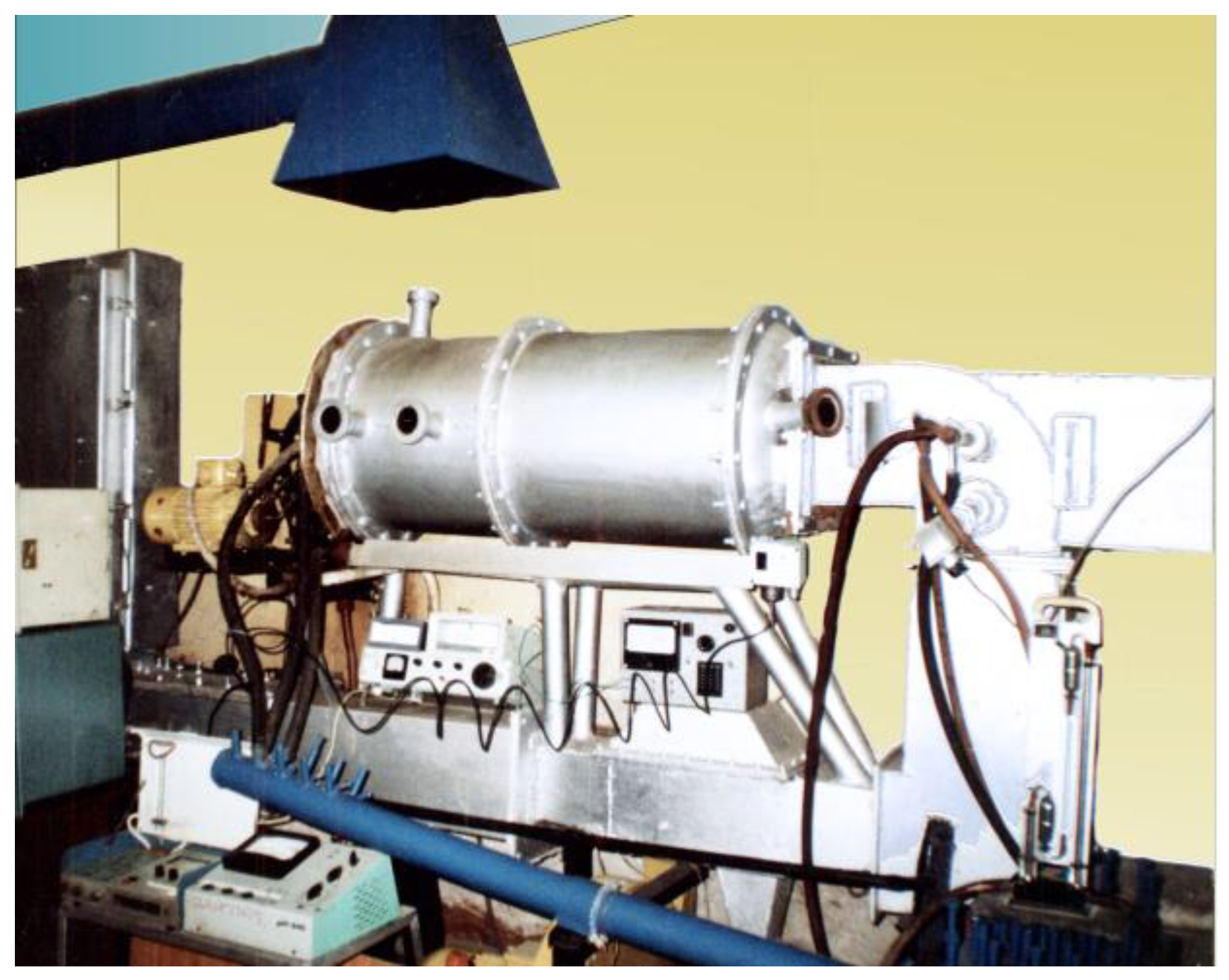
2.1. Experimental Research

For obtaining the reliability quantitative results of studies of corrosion processes during of WFE combustion, which are not presented in scientific publications, it is necessary to simultaneously determine the considered parameters characterizing corrosion during standard sulfur fuels combustion in the same experimental setup using the same methods. Comparison of the data obtained of standard fuel combustion with published scientific data will make it possible to assess the level of reliability of the results obtained at the same experimental setup with WFE combustion.
The studies were carried out on a special experimental setup. Research on such an installation, unlike research on an industrial unit, makes it possible to ensure the constancy of parameters (temperature, composition of exhaust gases, metal temperature). This will make it possible, with the smallest error, to establish the influence of individual operating and design factors on the ongoing corrosion processes when the combustion of both standard fuel and WFE are based on it. The general view of the experimental setup is shown in Figure 1.
The experimental setup consisted of the following elements: fuel preparation system, furnace, burner, gas duct. The shape of the furnace ensured good filling with a torch. Furnace dimensions were length—0.8 m, diameter—0.3 m. The furnace was lined with refractory bricks inside. Exhaust gases from the furnace entered a metal gas duct with a free cross-sectional area of 0.08 × 0.103 m. The gas duct was lined with refractory bricks. The furnace was cooled by heat transfer to the environment through the uncooled walls of the furnace.
Preparation of a WFE for combustion in the furnace of the experimental setup was carried out using a disperser according to a circulation scheme to obtain an emulsion with a water droplet diameter of 15–30 μm. The fuel system is used to supply 1–3 kg/h of fuel oil to the burner [43,44]. A rotary nozzle is used as a burner in the unit. As shown by preliminary commissioning tests of the experimental setup, with such diameters of water droplets, the best quality of combustion of WFE is achieved, due to the turbulence of the flame due to microexplosions of emulsion droplets.
A stable value of excess air factor α was ensured only by ensuring constant fuel consumption, since the air consumption remains practically unchanged. When a rotary nozzle was used, the constant fuel consumption was ensured by feeding it by gravity from a tank with a constant level (by installing an overflow pipe) and was monitored throughout each experiment for subsequent adjustment. With a constant air flow, even a slight change in fuel consumption leads to a change of the gas temperature at the outlet from the furnace, which served as a signal to adjust the fuel consumption. Analysis of exhaust gas composition at the furnace outlet was carried out by a chemical gas analyzer (determination of RO2 and O2), a chromatograph (determination of CO, H2, and CH4), and gas analyzers (determination of SOx and NOx). Determination of the speed and flow rate of exhaust gases in the gas duct was carried out using a high-speed pipe and an inclined differential manometer. The speed of exhaust gases in the area of installation of pipe samples in the main gas duct was about 8 m/s. Working section of pipe samples (Figure 2) to study corrosion processes in the low-temperature zone was installed in the zone of exhaust gas temperatures of about 250 °C. The temperature of exhaust gases and pipe samples were measured by thermocouples, which were on pipe samples and in spaces between the pipes.
The pipe samples were cooled with air from the receiver. Water or oil supplied from four thermostats was used for cooling the pipe samples in the gas temperature zone of 250 °C. Requirements for the accuracy of the conducted research determine the duration of the experiments and the transient modes that separate them, since with a long experiment duration, the drift of the processes in the research object and the measurement system increases. As a result of this, the error introduced by them becomes commensurate with the investigated value, especially with short experiments.
When short-term experimental studies are conducted, it is easier to ensure the stability of the parameters. The duration of research should be within 12 h, since during this time, a passivating layer of salts and oxides is formed on the metal surface. A total of 13 series of experimental studies were carried out, with duration from 2 to 12, 88, and 100 h, with a change of the water content of the combusted fuel from 2 to 30%, the sulfur content in the original fuel from 0.98 to 2%, and the excess air factor from 1.01 to 2.9. For assessing the reliability of the regression equations obtained from the results of short-term studies, to ensure the reliability of the forecast of the process development under consideration, we compared the calculated values with the experimental data during WFE and standard fuel oil combustion, as well as scientific data based on the results of long-term studies at industrial facilities when standard fuels were burnt. According to scientific data, the duration of corrosion studies on boilers ranges from 2 to 120 h.
The intensity of LTC process depends on the surface temperature tw, the content of water Wr, and sulfur Sr in the fuel, as well as on the excess air factor α during combustion. Investigations of corrosion processes were carried out in the wall temperature tw range of 60–180 °C; the adsorption of H2SO4 is observed in this temperature range. For obtaining the main dependences of the dynamic process development, the data obtained at wall temperatures in the region of the “acid peak” (tw = 105–110 °C) were used, at which the highest corrosion intensity was observed.
The sample for the study of the corrosion rate was a pipe with an outer diameter of 0.025 m and a wall thickness of 0.002–0.0025 m; the length of the sample was 0.08 m. Pipe samples of 20 steel were selected for corrosion studies (Figure 2a). The length of each sample was measured with a caliper with a graduation of 0.00005 m. The sample diameter was measured with a micrometer with a scale division of 0.00001 m at a distance of 0.01 m from each end of the pipe in two mutually perpendicular directions. The arithmetic mean of four measurements was taken as the calculated diameter. The obtained values were used to calculate the size of the outer surface of the sample F. The samples were then weighed and labeled. Weighing was carried out on an analytical balance with an optical scale division of 0.1 mg with a variation of the readings of 0.2 mg. The weight of sample is designated as w1.
The preparation of samples for testing was completed by assembling a package of pipe samples, installing thermocouples, and connecting them to a switch and secondary devices. At the end of the experiment, the working sections with the packages of pipe samples were removed from the gas ducts. The external views of the samples extracted from the gas duct under different modes are shown in Figure 2b.
Samples with corrosion products, acid, and deposits carefully removed from the working areas were weighed on an analytical balance (weight w2). Removal of deposits and corrosion products from the metal surface was carried out by processing the samples in a 5% solution of hydrochloric acid, inhibited by urotropine (1 g per 1 L of solution). Then, the samples were washed in water and B-70 gasoline, dried, and weighed again (weight m3) (Figure 3).

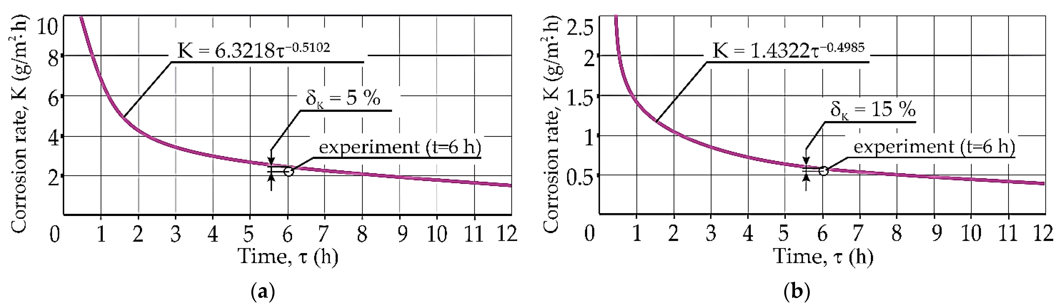
2.2. Processing of Experiment Results

The weight loss of metal ΔG was determined
Δ G = w 1 w 3 F ,
where ΔG—weight loss of metal, g/m2; w1—weight of sample before experiment, g; w3—weight of sample after cleaning of soot deposits and corrosion products, g; F—average area of the outer surface of the sample to the experiment, m2.
The corrosion speed of metal surface K at a certain temperature of the pipe wall was determined as
K = Δ G τ ,
where K—corrosion rate of metal surface, g/(m2⋅h); τ—duration of experiment, h.
The weight loss of metal on the condensation surface ΔG was determined by a formula.
The relative error in obtaining the corrosion rate was
Δ K K = ± ( Δ ( Δ w ) Δ w + Δ F F )
The relative error in measuring the area of the pipe sample was
Δ F F = Δ d d + Δ L L
The relative error in obtaining Δw was ∆(∆w)/∆w = 0.5%. The relative error in obtaining the area of the corrosion surface of the pipe sample was ∆F/F = 1.18%. The total relative error in determining the corrosion rate will be ∆K/K = 1.68%.
The systematic error in determining the corrosion rate was
Δ K = ( Δ w τ × F ) 2 + ( Δ w τ 2 × F × Δ τ ) 2 + ( Δ w τ × F 2 × Δ F ) 2
When corrosion tests are conducted, the limiting relative systematic error in determining the corrosion rate was assumed to be ∆K = 10%.
The systematic error in obtaining the area of the pipe sample was
Δ F = ( F d ex × Δ d ) 2 + ( F F av × Δ d ) 2 + ( F l × Δ L ) 2
With the accepted geometric dimensions of the sample, the value of systematic error was ΔF = 1.84 × 10⁻⁴ m2. The surface of the pipe sample was F = 0.082 m2.
The experimental data were processed on a PC using the specialized statistical package Sratgraphics Centurion XV in the Regression Model Selection module to find the most optimal regression equation using various functions: linear, exponential, logarithmic, polynomial, etc. The processing results showed that, with the smallest deviation, the dynamic of corrosion processes, taking into account all data, is described by a power function of the form ΔG = c × τn. In all the options considered, the coefficient of determination was higher than 0.8 (R2 = 0.91–0.99), which, from the viewpoint of the theory of statistics indicates a low dispersion of the obtained data and a fairly high reliability of the obtained regression equations. When processing the research results, we assumed that the process obeys the obtained regression equations from the very beginning of the impact of the exhaust gas flow.

2.3. Processing the Effect Gained Due to Deep Exhaust Gas Heat Recovering for Cooling the Air Sucked by Engine Turbocharger

A scheme of the system for cooling air at the suction of engine turbocharger by recovering the heat of exhaust gas in ECh was developed (Figure 4) [45,46]. The ECh consists of power and refrigeration generation circuits. A generator of power circuit uses the exhaust gas heat to produce a high-pressure refrigerant vapor as a motive fluid for ejector to suck the low-pressure refrigerant vapor from evaporator–turbocharger intake air cooler to compress it up to the pressure in the condenser. In its turn, the generator of power circuit includes evaporative and economizer sections. A high potential exhaust gas heat is consumed by evaporative section to generate a high-pressure refrigerant vapor as a motive fluid for ejector and economizer section for preheating liquid refrigerant coming from a condenser to the boiling temperature. With this, the economizer section consumes a low potential heat of exhaust gas gained due to deep exhaust gas heat recovering on low-temperature condensation surface of the economizer of EGB. The low potential heat of exhaust gas is revealed due to the reduction of corrosion of low-temperature condensation surface of the EGB economizer during WFE combustion.
The low-speed diesel engine 5S60ME-C10.5-TIII (nominal power Nn = 12,450 kW and continuous service power Ns = 10,580 kW) is considered as the main engine of transport ship [2]. On transport ships, about 25% of EGB steam productivity is spent for thermal processing of fuel and lubricating oil during warm time. It means that about 75% of the heat produced by EGB is available to be converted in refrigeration capacity by ECh for cooling the air sucked by the engine turbocharger. From this, the available refrigeration capacity of ECh and decrease in the temperature Δta of turbocharger sucked air due to its cooling by ECh, as well as the effect gained as engine fuel consumption reduction were calculated accordingly.
The air temperature depression in the air cooler at the suction of the engine turbocharger Δta = ta1–ta2 depends on the temperature ta1 of the air sucked from the engine room. When sailing in warm climatic conditions, the temperature of air in the engine room tER exceeds ambient air temperature by 10 °C [2].
The temperature ta2, which limits the air temperature depression Δta in the air cooler, depends on the boiling temperature of refrigerant, which is assumed of about t0 = 7 °C to provide a high COP of ECh.
Proceeding from the minimum value of temperature difference between cooled air and boiling refrigerant of 8 °C the minimum temperature of cooled air at the air cooler outlet ta2 = t0 + 8 = 15 °C. A refrigeration capacity Q0 of ECh is determined issuing from the available exhaust gas heat Qexh as Q0 = ζ Qexh, where ζ is the coefficient of performance for ECh of 0.30 to 0.35.

3. Results and Discussion

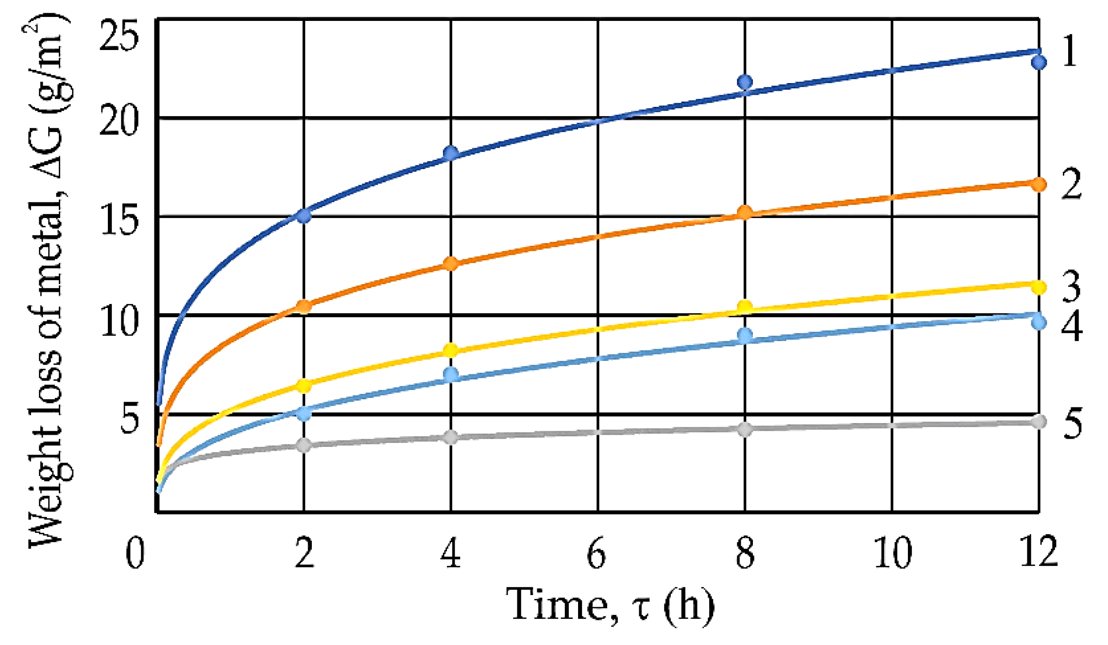
3.1. Corrosion Process Intensity

The dependences obtained under the most characteristic modes and displayed in Figure 5 shows that that with an increase in the water content of WFE Wr, the values of the weight loss of metal ΔG on the condensation surfaces at a wall temperature tw = 105–110 °C decreased.
As the results of experimental research have shown, the time for stabilization of corrosion process is 8 h, especially when WFE are burnt. This allows for the assessment of the level of corrosion process and to predict the process for a long period of time from the results of kinetic studies for 2–12 h.
The dependences of the weight loss of metal ΔG = f (τ) (Figure 6) were obtained as a result of processing the series of experiments. Dependences have shown that for standard fuel oil with a water content of 2%, the corrosion rate is about five times higher than during WFE combustion with a water content of about 30%. This is explained by a protective passivating film formed on the tube metal surface.
In Figure 7, we see the dependences of the change of corrosion rate for two modes of combustion of fuels with Wr = 2% and Wr = 30%, indicating the magnitude of the deviation between the predicted and control experimental values K = f (τ). The deviations between the experimental data and the predicted values did not exceed 15% (Figure 7), which is considered acceptable in the study of the processes and confirms the reliability of research results and approximation equations of corrosion processes under different modes obtained during 2–12 h.
This allows, under the same working conditions, for the determination (prediction) of the value of ΔG by calculation during any period of operation, but while ensuring stable operating modes.
In order to assess the reliability of the research results obtained in 2–12 h and the approximating dependencies for predicting the corrosion intensity, we carried out control (main) studies (two modes) with a long duration: when WFE combustion (Wr = 30%) based on M40 (Sr = 1.5%) and α = 2.9 at τ = 88 h; when fuel oil M40 combustion (Wr = 2%, Sr = 1.5%) with α = 2.9 at τ = 100 h.
The results of the comparison of the obtained values of the average corrosion rate according to the kinetic equations (predicted) (Figure 7) with the experimental data for 88 and 100 h, presented in Figure 8, shows that their discrepancy with the values in the region of the acid peak at tw = 110 °C was insignificant and less than 5%.
Dependences (Figure 8) make it possible to determine the minimum wall temperature of the low-temperature surface according to the corrosion rate accepted under the conditions of reliability and service life. Considering the permissible corrosion rate (Kp) of the metal of the economizer at the level of 0.25–0.35 mm/year, one can argue that the most dangerous level of LTC is the wall temperature range tw = 85–130 °C, because this part of the surface is subjected to intense exposure to sulfuric acid condensate. In this range of wall temperatures, the “acid peak” of corrosion is observed, and the corrosion rate is well above the allowable level.
At wall temperature range tw = 130–150 °C, the economizer surface was in the zone of electrochemical corrosion. With a decreasing of tw to 100–115 °C, the corrosion rate during fuel oil combustion increased sharply. In this tw range, the first “acid peak” of corrosion was observed, and K was significantly higher than Kp. With a further decreasing of wall temperature tw, corrosion rate K decreased, and the second “corrosion minimum” was reached. In the temperature range 80–90 °C, a decreasing corrosion rate K to Kp was observed, mainly at low excess air factor α. At increased α, the corrosion rate was higher than K. However, since this range of tw was very narrow and it was located after the “acid peak”, it was difficult to use this phenomenon in the design of the condensation surface. At tw below 75–80 °C, the corrosion rate increased sharply again (the second “acid peak”).
When WFE was burnt with water content 30%, there was no “acid peak”. Within the wall temperature varying from 140 to 70 °C, the corrosion rate was at the level of 0.15–0.25 mm/year. As a result, the corrosion intensity of the WFE combustion was reduced by six times compared to fuel combustion with Wr = 2%. The service life of the economizer surfaces increased proportionally. This means that, when WFE were burnt, the lifetime of the condensation surface was the same as that of the dry one.
The range of wall temperatures within 130 °C down to 70 °C of condensation economizer were determined as having safe operation, which revealed the potential for deep exhaust gas heat utilization as compared with 150 °C down to 90 °C for conventional fuel oil combustion.

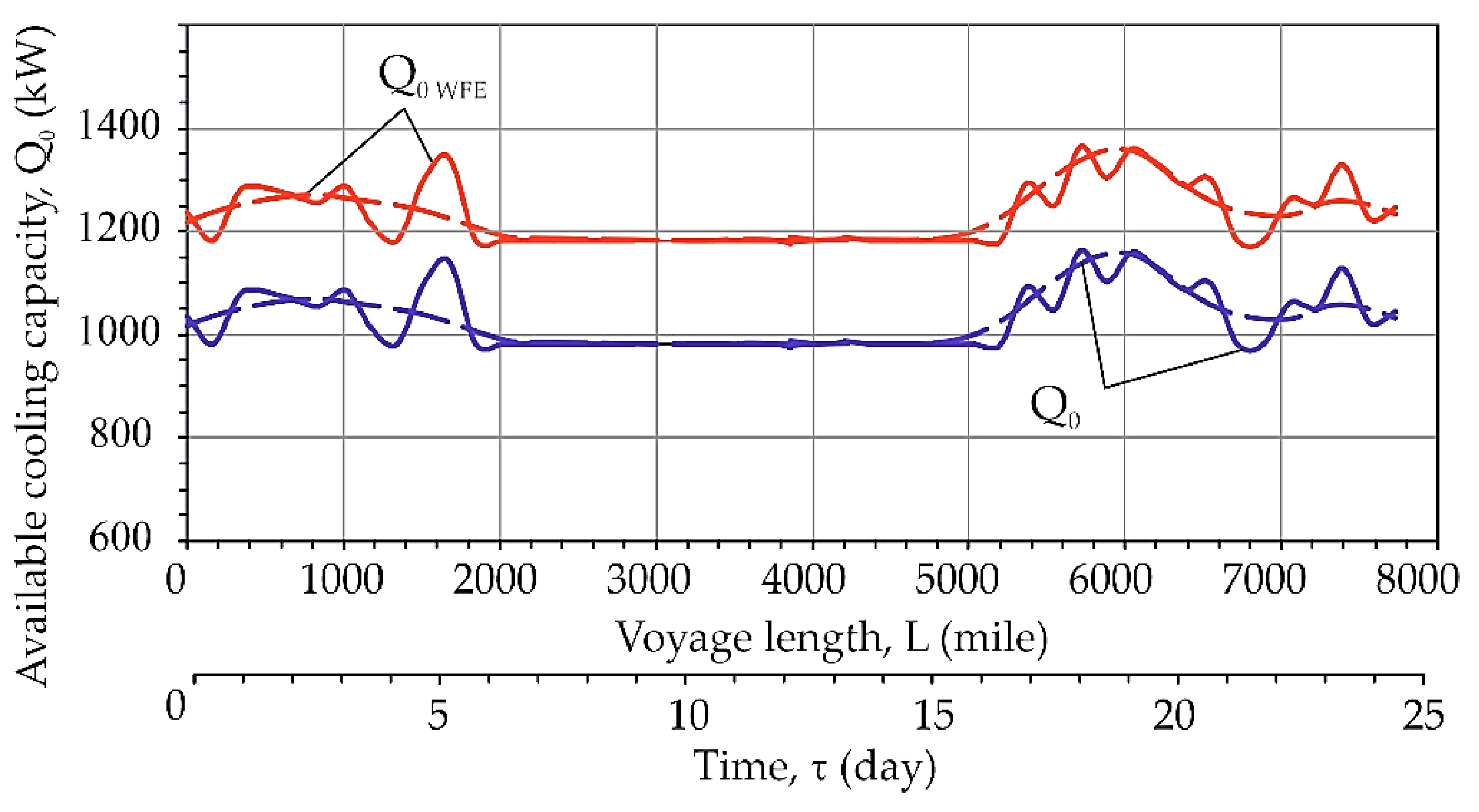
3.2. Processing the Results of Evaluation of the Effect Gained Due to Cooling Marine Diesel Engine Turbocharger Suction Air by ECh on the Voyage Line Mariupol–Amsterdam–Mariupol

A voyage line Mariupol–Amsterdam–Mariupol was considered to evaluate the enhancement of marine engine fuel efficiency due to turbocharger sucked air cooling by ECh converting exhaust gas heat enlarged with WFE combusting compared with conventional fuel oil. The values of temperature tamb and relative humidity φamb of ambient air during voyage line were fixed each 3 h (Figure 9).
As Figure 9 shows that during a summer voyage, the temperatures of ambient air tamb varied from 15 to 20 °C in middle widths compared with 25 to 30 °C in southern widths (accordingly air temperature in engine room is 10 °C higher), and relative humidity of air φamb were from 50 to 60% in the Mediterranean Sea compared with 80 to 90% in Northwest Europe.
For each 3 h interval, we calculated the corresponding ambient air temperature tamb and relative humidity φamb, as well as the processes of cooling the engine turbocharger sucked air in the air cooler from the air temperature in engine room (at the air cooler inlet) ta1 = tamb + 10 °C to its temperature ta2 at the outlet of air cooler (at the turbocharger suction).
The values of the available cooling capacity Q0.WFE of ECh using the enlarged exhaust gas heat during WFE combustion was higher compared with Q0 for fuel oil combustion due to deeper exhaust gas heat utilization to lowered temperatures texh2 = 90–110 °C compared with texh2 = 150–170 °C (Figure 10).
Accordingly, the values of air temperature depression in the air cooler at the engine turbocharger suction Δta during WFE combustion Δta.WFE were higher compared with Δta for oil fuel (Figure 11).
As Figure 11 shows, temperature depression in the sucked air cooler of ECh recovered the exhaust gas heat (scheme in Figure 4) Δta = 10–20 °C during oil fuel combustion, whereas Δta = 15–25 °C for WFE.
We found a reduction in specific fuel consumption Δbe, as well as saving of fuel consumption in absolute values Be, t, and relative values B’e, %, related to the total fuel consumption for low-speed diesel engine 5S60ME-C10.5-TIII on the voyage line Mariupol–Amsterdam–Mariupol due to cooling turbocharger suction air by ECh, using the exhaust gas heat, calculated by program “mandieselturbo” [2], which is shown in Figure 12.
As Figure 12 shows, we found a reduction of specific fuel consumption due to cooling turbocharger suction air by ECh, utilizing exhaust gas heat, Δbe = 1.2–2.5 g/(kW∙h), absolute values Be ≈ 10 t, and relative values B’e = 1.2–1.3% of fuel saving are gained for convention oil fuel combustion, whereas Δbe = 1.2–2.5 g/(kW∙h), BeWFE ≈ 10 t, and B’eWFE = 1.2–1.3% for WFE combustion in low-speed diesel engine 5S60ME-C10.5-TIII on the voyage line Mariupol–Amsterdam–Mariupol (22 July 2019–3 August 2019).
The further enhancement in fuel saving by about 1.5 times was possible due to complex cooling the engine turbocharger sucked air and scavenge air through using additional scavenge air heat in ECh or in combined absorption-ejector chiller with ACh as a high-temperature stage to precool the engine turbocharger sucked air to about 15 °C and ECh as a low-temperature stage to subcool it to 15 °C and lower (Figure 13).

4. Conclusions

Additional refrigeration capacity can be used to increase a depth of cooling intake air at the suction of internal combustion engines by waste heat recovery chillers due to deep utilization of exhaust gas heat, making it possible to reduce engine fuel consumption and, accordingly, the amount of harmful emissions.
In its turn, deep utilization of exhaust gas heat of diesel engines is limited by the low-temperature corrosion processes of EGB surfaces.
The application of WFE combustion enables the reduction of a LTC, and as result provides deeper exhaust gas heat utilization in the EGB to the much lower temperature 90–110 °C with WFE instead of 150–170 °C when combusting conventional fuel oil.
Analysis of literary sources showed that there were no quantitative data of the low-temperature corrosion intensity of EGB condensation surfaces during WFE combustion.
Experimental research of corrosion intensity at wall temperature values below dew point temperature of sulfuric acid vapors were carried out at the experimental setup with combustion of fuel oils and WFE based on them.
Proceeding from the research results, we revealed that the stabilization of the corrosion process occurred within 8 h. Regression equations were obtained that reliably estimated the development of corrosion processes. The study of the kinetics of corrosion processes was reliably approximated by power functions with an error of 5 to 15%.
The range of wall temperatures of condensation economizer safe operation within 130 °C down to 70 °C when WFE combustion was determined on the basis of the experimental data that allow for a decrease in the exhaust gas temperature from 150 °C down to 90 °C and an increase in the potential for deep exhaust gas heat utilization as compared with conventional fuel oil combustion.
The results of experimental research of low-temperature condensation economizer approved the appropriate corrosion rate during WFE combustion and provide a good perspective for their application in marine diesel engine waste heat recovery.
A diesel engine sucked air cooling system with deep utilization of the exhaust gas heat potential was enlarged due to using the low potential heat in economizer section of ECh generator when WFE combustion was developed as a novel trend in enhancing the fuel efficiency of marine diesel engines by waste heat recovery.
The application of developed diesel engine sucked air cooling system provided 1.3 to 1.7% fuel saving on the voyage line Mariupol–Amsterdam–Mariupol and revealed good perspectives for increasing the fuel saving by 1.5 times due to complex engine intake air cooling through using additional heat of scavenged air in ECh or in combined absorption–ejector chiller.

Author Contributions

Conceptualization, V.K., R.R. and M.R.; methodology, V.K., R.R. and M.R.; software, V.K. and R.R.; validation, V.K., R.R., M.R., A.R. and D.K.; formal analysis, V.K., M.R., A.R., R.R., A.P. and D.K.; investigation, V.K., R.R., M.R., A.R., A.P. and D.K.; resources, V.K.; data curation, V.K., R.R. and A.R.; writing—original draft preparation, V.K.; writing—review and editing, V.K., R.R. and M.R.; visualization, V.K. and A.R.; supervision, M.R.; project administration, M.R.; funding acquisition, A.P. All authors have read and agreed to the published version of the manuscript.

Funding

This research received no external funding.

Institutional Review Board Statement

Not applicable.

Informed Consent Statement

Not applicable.

Data Availability Statement

Not applicable.

Conflicts of Interest

The authors declare no conflict of interest.

Nomenclature

AChabsorption lithium-bromide chillers
COPcoefficient of performance
EChejector chiller
EGBexhaust gas boiler
LTClow-temperature corrosion
WFEwater-fuel emulsion
Symbols and units
Betotal mass fuel consumption decreaseg, kg, t
Kcorrosion rate of metal surface
Q0total cooling capacity, heat flow ratekW
Qexhexhaust gas heat kW
tambambient air temperature°C
ta1inlet air temperature °C
ta2outlet air temperature °C
t0refrigerant boiling temperature°C
tERair temperature in the engine room °C
twwall temperature of condensation economizer°C
w1weight of sample before experimentg
w2weight of sample after experimentg
w3weight of sample after cleaning of soot deposits and corrosion productsg
Δbespecific fuel consumption decrease g/kW h
ΔGweight loss of metalg/m2
Δtaair temperature decrease, depression, reduction K, °C
φambambient air relative humidity %
τtime intervalh
ζcoefficient of performance
Subscripts
aair
ambambient
exhexhaust
WFEwater-fuel emulsion

References

  1. Kornienko, V.; Radchenko, M.; Radchenko, R.; Konovalov, D.; Andreev, A.; Pyrysunko, M. Improving the efficiency of heat recovery circuits of cogeneration plants with combustion of water-fuel emulsions. Therm. Sci. 2021, 25, 791–800. [Google Scholar] [CrossRef] [Green Version]
  2. MAN Diesel Turbo, CEAS Engine Calculations. Available online: https://marine.man-es.com/two-stroke/ceas (accessed on 22 June 2019).
  3. Butrymowicz, D.; Gagan, J.; Smierciew, K.; Łukaszuk, M.; Dudar, A.; Pawluczuk, A.; Łapinski, A.; Kuryłowicz, A. Investigations of prototype ejection refrigeration system driven by low grade heat. E3S Web. Conf. 2018, 70, 03002. [Google Scholar] [CrossRef]
  4. Konovalov, D.; Kobalava, H.; Radchenko, M.; Scurtu, I.C.; Radchenko, R. Determination of hydraulic resistance of the aerothermopressor for gas turbine cyclic air cooling. In E3S Web Conference, Proceedings of the 9th International Conference on Thermal Equipments, Renewable Energy and Rural Development (TE-RE-RD 2020), Constanta, Romania, 26–27 June 2020; EDP Sciences: Les Ulis, France, 2020; Volume 180, p. 01012. [Google Scholar] [CrossRef]
  5. Konovalov, D.; Kobalava, H.; Radchenko, M.; Sviridov, V.; Scurtu, I.C. Optimal sizing of the evaporation chamber in the low-flow aerothermopressor for a combustion engine. In Lecture Notes in Mechanical Engineering, Advanced Manufacturing Processes II, Proceedings of the 2nd Grabchenko’s International Conference on Advanced Manufacturing Processes (InterPartner-2020), Odessa, Ukraine, 8–11 September 2020; Tonkonogyi, V., Ivanov, V., Trojanowska, J., Oborskyi, G., Grabchenko, A., Pavlenko, I., Edl, M., Kuric, I., Dasic, P., Eds.; Springer: Cham, Switzerland, 2021; pp. 654–663. [Google Scholar] [CrossRef]
  6. Radchenko, A.; Trushliakov, E.; Tkachenko, V.; Portnoi, B.; Prjadko, O. Improvement of the refrigeration capacity utilizing for the ambient air conditioning system. In Lecture Notes in Mechanical Engineering, Advanced Manufacturing Processes II, Proceedings of the 2nd Grabchenko’s International Conference on Advanced Manufacturing Processes (InterPartner-2020), Odessa, Ukraine, 8–11 September 2020; Tonkonogyi, V., Ivanov, V., Trojanowska, J., Oborskyi, G., Grabchenko, A., Pavlenko, I., Edl, M., Kuric, I., Dasic, P., Eds.; Springer: Cham, Switzerland, 2021; pp. 714–723. [Google Scholar] [CrossRef]
  7. Radchenko, R.; Pyrysunko, M.; Radchenko, A.; Andreev, A.; Kornienko, V. Ship engine intake air cooling by ejector chiller using recirculation gas. In Lecture Notes in Mechanical Engineering, Advanced Manufacturing Processes II, Proceedings of the 2nd Grabchenko’s International Conference on Advanced Manufacturing Processes (InterPartner-2020), Odessa, Ukraine, 8–11 September 2020; Tonkonogyi, V., Ivanov, V., Trojanowska, J., Oborskyi, G., Grabchenko, A., Pavlenko, I., Edl, M., Kuric, I., Dasic, P., Eds.; Springer: Cham, Switzerland, 2021; pp. 734–743. [Google Scholar] [CrossRef]
  8. Kumar Ojha, M.; Kumar Shukla, A.; Verma, P.; Kannojiya, R. Recent progress and outlook of solar adsorption refrigeration systems. Mater. Today Proc. 2021, 46, 5639–5646. [Google Scholar] [CrossRef]
  9. Radchenko, A.; Stachel, A.; Forduy, S.; Portnoi, B.; Rizun, O. Analysis of the efficiency of engine inlet air chilling unit with cooling towers. In Lecture Notes in Mechanical Engineering, Advances in Design, Simulation and Manufacturing III, Proceedings of the 3rd International Conference on Design, Simulation, Manufacturing: The Innovation Exchange, DSMIE-2020, Kharkiv, Ukraine, 9–12 June 2020; Ivanov, V., Pavlenko, I., Liaposhchenko, O., Machado, J., Edl, M., Eds.; Springer: Cham, Switzerland, 2020; pp. 322–331. [Google Scholar] [CrossRef]
  10. Radchenko, M.; Radchenko, A.; Radchenko, R.; Kantor, S.; Konovalov, D.; Kornienko, V. Rational loads of turbine inlet air absorption-ejector cooling systems. Proc. Inst. Mech. Eng. Part A J. Power Energy 2021. [Google Scholar] [CrossRef]
  11. Sadighi Dizaji, H.; Jing Hu, E.; Chen, L.; Pourhedayat, S. Using novel integrated Maisotsenko cooler and absorption chiller for cooling of gas turbine inlet air. Energy Convers. Manag. 2019, 195, 1067–1078. [Google Scholar] [CrossRef]
  12. Radchenko, A.; Trushliakov, E.; Kosowski, K.; Mikielewicz, D.; Radchenko, M. Innovative turbine intake air cooling systems and their rational designing. Energies 2020, 13, 6201. [Google Scholar] [CrossRef]
  13. Elberry, M.F.; Elsayed, A.A.; Teamah, M.A.; Abdel-Rahman, A.A.; Elsafty, A.F. Performance improvement of power plants using absorption cooling system. Alex. Eng. J. 2018, 57, 2679–2686. [Google Scholar] [CrossRef]
  14. Bohdal, T.; Kuczynski, W. Boiling of R404A refrigeration medium under the conditions of periodically generated disturbances. Heat Transf. Eng. 2011, 32, 359–368. [Google Scholar] [CrossRef]
  15. Mikielewicz, D.; Wajs, J.; Andrzejczyk, R.; Klugmann, M. Pressure drop of HFE7000 and HFE7100 during flow condensation in minichannels. Int. J. Refrig. 2016, 68, 226–241. [Google Scholar] [CrossRef]
  16. Mikielewicz, D.; Kosowski, K.; Tucki, K.; Piwowarski, M.; Stepie ´n, R.; Orynycz, O.; Włodarski, W. Gas turbine cycle with external combustion chamber for prosumer and distributed energy systems. Energies 2019, 12, 3501. [Google Scholar] [CrossRef] [Green Version]
  17. Radchenko, M.; Radchenko, R.; Tkachenko, V.; Kantor, S.; Smolyanoy, E. Increasing the operation efficiency of railway air conditioning system on the base of its simulation along the route line. In Advances in Intelligent Systems and Computing, International Scientific and Technical Conference on Integrated Computer Technologies in Mechanical Engineering-Synergetic Engineering, Proceedings of the ICTM 2019, Kharkiv, Ukraine, 28–30 November 2019; Nechyporuk, M., Pavlikov, V., Kritskiy, D., Eds.; Springer: Cham, Switzerland, 2020; Volume 1113, pp. 461–467. [Google Scholar] [CrossRef]
  18. Radchenko, M.; Mikielewicz, D.; Tkachenko, V.; Klugmann, M.; Andreev, A. Enhancement of the operation efficiency of the transport air conditioning system. In Lecture Notes in Mechanical Engineering, Advances in Design, Simulation and Manufacturing III, Proceedings of the 3rd International Conference on Design, Simulation, Manufacturing: The Innovation Exchange, DSMIE-2020, Kharkiv, Ukraine, 9–12 June 2020; Ivanov, V., Pavlenko, I., Liaposhchenko, O., Machado, J., Edl, M., Eds.; Springer: Cham, Switzerland, 2020; pp. 332–342. [Google Scholar] [CrossRef]
  19. Kumar Shukla, A.; Singh, O. Thermodynamic investigation of parameters affecting the execution of steam injected cooled gas turbine based combined cycle power plant with vapor absorption inlet air cooling. Appl. Therm. Eng. 2017, 122, 380–388. [Google Scholar] [CrossRef]
  20. Kumar Shukla, A.; Sharma, A.; Sharma, M.; Mishra, S. Performance improvement of simple gas turbine cycle with vapor compression inlet air cooling. Mater. Today Proc. 2018, 5, 19172–19180. [Google Scholar] [CrossRef]
  21. Trushliakov, E.; Radchenko, A.; Forduy, S.; Zubarev, A.; Hrych, A. Increasing the operation efficiency of air conditioning system for integrated power plant on the base of its monitoring. In Advances in Intelligent Systems and Computing, International Scientific and Technical Conference on Integrated Computer Technologies in Mechanical Engineering-Synergetic Engineering, Proceedings of the ICTM 2019, Kharkiv, Ukraine, 28–30 November 2019; Nechyporuk, M., Pavlikov, V., Kritskiy, D., Eds.; Springer: Cham, Switzerland, 2020; Volume 1113, pp. 351–360. [Google Scholar] [CrossRef]
  22. Trushliakov, E.; Radchenko, A.; Radchenko, M.; Kantor, S.; Zielikov, O. The efficiency of refrigeration capacity regulation in the ambient air conditioning systems. In Lecture Notes in Mechanical Engineering, Advances in Design, Simulation and Manufacturing III, Proceedings of the 3rd International Conference on Design, Simulation, Manufacturing: The Innovation Exchange, DSMIE-2020, Kharkiv, Ukraine, 9–12 June 2020; Ivanov, V., Pavlenko, I., Liaposhchenko, O., Machado, J., Edl, M., Eds.; Springer: Cham, Switzerland, 2020; pp. 343–353. [Google Scholar] [CrossRef]
  23. Shamsi, S.S.M.; Negash, A.A.; Cho, G.B.; Kim, Y.M. Waste heat and water recovery system optimization for flue gas in thermal power plants. Sustainability 2019, 11, 1881. [Google Scholar] [CrossRef] [Green Version]
  24. Luo, C.; Luo, K.; Wang, Y.; Ma, Z.; Gong, Y. The effect analysis of thermal efficiency and optimal design for boiler system. Energy Procedia 2017, 105, 3045–3050. [Google Scholar]
  25. Baldi, S.; Quang, T.L.; Holub, O.; Endel, P. Real-time monitoring energy efficiency and performance degradation of condensing boilers. Energy Convers. Manag. 2017, 136, 329–339. [Google Scholar] [CrossRef]
  26. Li, F.; Duanm, L.; Fu, L.; Zhao, X. Research and application of flue gas waste heat recovery in cogeneration based on absorption heat–exchange. Procedia Eng. 2016, 146, 594–603. [Google Scholar] [CrossRef] [Green Version]
  27. Sugeng, D.A.; Ithnin, A.M.; Amri, N.S.M.S.; Ahmad, M.A.; Yahya, W.J. Water content determination of steam generated water-in-diesel emulsion. J. Adv. Res. Fluid Mech. Therm. Sci. 2018, 49, 62–68. [Google Scholar]
  28. Fan, C.; Pei, D.; Wei, H. A novel cascade energy utilization to improve efficiency of double reheat cycle. Energy Convers. Manag. 2018, 171, 1388–1396. [Google Scholar] [CrossRef]
  29. Wojs, M.K.; Orliński, P.; Kamela, W.; Kruczyński, P. Research on the influence of ozone dissolved in the fuel-water emulsion on the parameters of the CI engine. In IOP Conference Series: Materials Science and Engineering, Proceedings of the Scientific Conference on Automotive Vehicles and Combustion Engines (KONMOT 2016), Krakow, Poland, 22–23 September 2016; IOP Publishing Ltd.: Bristol, UK, 2016; Volume 148, p. 012089. [Google Scholar]
  30. Miao, Y.C.; Yu, C.L.; Wang, B.H.; Chen, K. The applied research of emulsified heavy fuel oil used for the marine diesel engine. Adv. Mater. Res. 2013, 779, 469–476. [Google Scholar] [CrossRef]
  31. Baskar, P.; Senthil Kumar, A. Experimental investigation on performance characteristics of a diesel engine using diesel-water emulsion with oxygen enriched air. Alex. Eng. J. 2017, 56, 137–146. [Google Scholar] [CrossRef] [Green Version]
  32. Gupta, R.K.; Sankeerth, K.A.; Sharma, T.K.; Rao, G.; Murthy, K.M. Effects of water-diesel emulsion on the emission characteristics of single cylinder direct injection diesel engine-A review. Appl. Mech. Mater. 2014, 592, 1526–1533. [Google Scholar] [CrossRef]
  33. Patel, K.R.; Dhiman, V. Research study of water- diesel emulsion as alternative fuel in diesel engine–An overview. Int. J. Latest Eng. Res. Appl. 2017, 2, 37–41. [Google Scholar]
  34. Saha, D.; Sinha, A.; Sinha, A.; Roy, B.; Mishra, L. Effects of water-diesel emulsification on performance and emission characteristics of CI engine: A review. In Lecture Notes in Mechanical Engineering, Proceedings of the International Conference on Innovations in Thermo-Fluid Engineering and Sciences, ICITFES 2020, Rourkela, India, 10–12 February 2020; Palanisamy, M., Natarajan, S.K., Jayaraj, S., Sivalingam, M., Eds.; Springer: Cham, Switzerland, 2022; Part F1; pp. 95–107. [Google Scholar]
  35. Kornienko, V.; Radchenko, R.; Bohdal, Ł.; Kukiełka, L.; Legutko, S. Investigation of condensing heating surfaces with reduced corrosion of boilers with water-fuel emulsion combustion. In Lecture Notes in Networks and Systems: In Advances in Intelligent Systems and Computing, Proceedings of the International Scientific and Technical Conference on Integrated Computer Technologies in Mechanical Engineering-Synergetic Engineering, ICTM 2020, Kharkiv, Ukraine, 29–30 October 2020; Nechyporuk, M., Pavlikov, V., Kritskiy, D., Eds.; Springer: Cham, Switzerland, 2021; Volume 188, pp. 300–309. [Google Scholar] [CrossRef]
  36. Ossai, C.I. Pipeline corrosion prediction and reliability analysis: A systematic approach with Monte Carlo simulation and degradation models. Int. J. Sci. Technol. Res. 2013, 2, 58–69. [Google Scholar]
  37. Akimov, O.V. Dynamics of reduction of ash and soot emissions during combustion of water-oil emulsions in boilers. Scientific works: Scientific and methodical journal. Technog. Saf. 2008, 95, 39–46. [Google Scholar]
  38. Akimov, O. Heat-transfer rate and influence of layer thickness of contaminations of low-temperature heat surfaces while burning water-fuel emulsions in boilers. Bull. Ternopol Natl. Tech. Univ. 2014, 1, 93–101. [Google Scholar]
  39. Bohdal, L.; Kukielka, L.; Radchenko, A.M.; Patyk, R.; Kułakowski, M.; Chodór, J. Modelling of guillotining process of grain oriented silicon steel using FEM. AIP Conf. Proc. 2019, 2078, 020080. [Google Scholar]
  40. Bohdal, L.; Kukiełka, L.; Legutko, S.; Patyk, R.; Radchenko, A.M. Modeling and Experimental Analysis of Shear-Slitting of AA6111-T4 Aluminum Alloy Sheet. Materials 2020, 13, 3175. [Google Scholar] [CrossRef] [PubMed]
  41. Kumar Shukla, A.; Singh, O. Performance evaluation of steam injected gas turbine based power plant with inlet evaporative cooling. Appl. Therm. Eng. 2016, 102, 454–464. [Google Scholar] [CrossRef]
  42. Bohdal, Ł.; Kukielka, L.; Świłło, S.; Radchenko, A.M.; Kułakowska, A. Modelling and experimental analysis of shear-slitting process of light metal alloys using FEM, SPH and vision-based methods. AIP Conf. Proc. 2019, 2078, 020060. [Google Scholar]
  43. Kornienko, V.; Radchenko, R.; Konovalov, D.; Andreev, A.; Pyrysunko, M. Characteristics of the rotary cup atomizer used as afterburning installation in exhaust gas boiler flue. In Lecture Notes in Mechanical Engineering, Advances in Design, Simulation and Manufacturing III, Proceedings of the 3rd International Conference on Design, Simulation, Manufacturing: The Innovation Exchange, DSMIE-2020, Kharkiv, Ukraine, 9–12 June 2020; Ivanov, V., Pavlenko, I., Liaposhchenko, O., Machado, J., Edl, M., Eds.; Springer: Cham, Switzerland, 2020; pp. 302–311. [Google Scholar] [CrossRef]
  44. Kornienko, V.; Radchenko, R.; Mikielewicz, D.; Pyrysunko, M.; Andreev, A. Improvement of characteristics of water-fuel rotary cup atomizer in a boiler. In Lecture Notes in Mechanical Engineering, Advanced Manufacturing Processes II, Proceedings of the 2nd Grabchenko’s International Conference on Advanced Manufacturing Processes (InterPartner-2020), Odessa, Ukraine, 8–11 September 2020; Tonkonogyi, V., Ivanov, V., Trojanowska, J., Oborskyi, G., Grabchenko, A., Pavlenko, I., Edl, M., Kuric, I., Dasic, P., Eds.; Springer: Cham, Switzerland, 2021; pp. 664–674. [Google Scholar] [CrossRef]
  45. Radchenko, R.; Kornienko, V.; Radchenko, M.; Mikielewicz, D.; Andreev, A.; Kalinichenko, I. Cooling intake air of marine engine with water-fuel emulsion combustion by ejector chiller. In E3S Web Conference, Proceedings of the V International Scientific and Technical Conference Modern Power Systems and Units (MPSU 2021), Krakow, Poland, 19–21 May 2021; EDP Sciences: Les Ulis, France, 2021; Volume 323, p. 00031. [Google Scholar] [CrossRef]
  46. Radchenko, R.; Pyrysunko, M.; Kornienko, V.; Scurtu, I.-C.; Patyk, R. Improving the ecological and energy efficiency of internal combustion engines by ejector chiller using recirculation gas heat. In Lecture Notes in Networks and Systems: In Advances in Intelligent Systems and Computing, Proceedings of the International Scientific and Technical Conference on Integrated Computer Technologies in Mechanical Engineering—Synergetic Engineering, ICTM 2020, Kharkiv, Ukraine, 29–30 October 2020; Nechyporuk, M., Pavlikov, V., Kritskiy, D., Eds.; Springer: Cham, Switzerland, 2021; Volume 188, pp. 531–541. [Google Scholar] [CrossRef]
Figure 1. Experimental setup.
Energies 15 00248 g001
Figure 2. Installing of samples for research of LTC: (a) before tests; (b) after the tests.
Energies 15 00248 g002
Figure 3. Drawing of corrosion processes investigated.
Energies 15 00248 g003
Figure 4. Scheme of the system for cooling the air at the suction of engine turbocharger by recovering the heat of exhaust gas: DE—diesel engine; T—turbine and C—compressor of turbocharger; SAC—scavenge air cooler; EGB—exhaust gas boiler; Gev—evaporative section of generator consuming steam condensed; Gec—economizer section of generator consuming hot water; E-AC—evaporator-air cooler; Ej—ejector; EV—expansion valve; P—pump; DC—droplet catcher; Con-t—condensate; Ac—accumulator of feed water; SS—steam separator; HC—heat consumer; CE—low-temperature condensation economizer of EGB.
Energies 15 00248 g004
Figure 5. Dependences of corrosion processes for the most characteristic modes: 1—Sr = 1.5%, α = 2.9, Wr = 2%; 2—Sr = 1.5%, α = 1.25, Wr = 2%; 3—Sr = 0.98%, α = 1.35, Wr = 15%; 4—Sr = 2%, α = 1.01, Wr = 2%; 5—Sr = 1.5%, α = 1.15, Wr = 30%.
Energies 15 00248 g005
Figure 6. Dependences of the weight loss of metal ΔG on time of experiments τ under fuel oil (Sr = 1.5%, α = 2.9, Wr = 2%) (a) and WFE (Sr = 1.5%, α = 2.9, Wr = 30%) (b) combustion.
Energies 15 00248 g006
Figure 7. Dependences of the corrosion rate K on time of experiments τ under fuel oil (Sr = 1.5%, α = 2.9, Wr = 2%) (a) and WFE (Sr = 1.5%, α = 2.9, Wr = 30%) (b) combustion.
Energies 15 00248 g007
Figure 8. Dependences of corrosion rate K on wall temperature tw.
Energies 15 00248 g008
Figure 9. Ambient air temperature tamb and relative humidity φamb variations on the voyage line Mariupol–Amsterdam–Mariupol (22 July 2019–3 August 2019).
Energies 15 00248 g009
Figure 10. The available cooling capacities of ECh: Q0—fuel oil; Q0.WFE—WFE.
Energies 15 00248 g010
Figure 11. The values of air temperature depression at the engine turbocharger suction: Δta—fuel oil; Δta WFE—WFE.
Energies 15 00248 g011
Figure 12. Reduction of specific fuel consumption Δbe, g/(kW h), of low-speed diesel engine, as well as fuel saving in absolute Be, t, and relative B’e, %, values as related to the total fuel consumption on the route line Mariupol–Amsterdam–Mariupol (22 July 2019–3 August 2019): Δbe, Be, and B’e—convention oil fuel; Δbe WFE, Be WFE, and B’e WFE—WFE.
Energies 15 00248 g012
Figure 13. The values of air temperature depression Δta and temperature ta2 of cooled air at the engine turbocharger suction when using exhaust gas heat and additional scavenge air heat: ta2 and Δta—fuel oil; ta2 WFE and Δta WFE—WFE.
Energies 15 00248 g013
Publisher’s Note: MDPI stays neutral with regard to jurisdictional claims in published maps and institutional affiliations.

