Article

Gas Hold-Up and Mass Transfer in a Vessel with an Unsteady Rotating Concave Blade Impeller

by
Sebastian Frankiewicz
and
Szymon Woziwodzki
*
Division of Chemical Engineering and Equipment, Poznan University of Technology, 60-965 Poznan, Poland
*
Author to whom correspondence should be addressed.
Energies 2022, 15(1), 346; https://doi.org/10.3390/en15010346
Submission received: 8 November 2021 / Revised: 13 December 2021 / Accepted: 1 January 2022 / Published: 4 January 2022
(This article belongs to the Special Issue Multiphase Flows)

Abstract

:
The steady mixing of gas-liquid systems is used where a large development of the interfacial area is required. However, the presence of gas in the liquid reduces the efficiency of mass transfer by reducing the mixing power, due to the creation of gas formations behind the impeller blades and the reduction in density. The efficiency of mass transfer can be increased by using a concave blade impeller or unsteady mixing. Mass transfer efficiency studies for these impellers and unsteady mixing are limited. This paper presents an analysis of the influence of the impeller construction on the gas hold-up and volumetric mass transfer coefficient kLa. Impellers with a different number of concave blades, and with alternatively arranged concave blades, were analyzed. The obtained results were compared with the standard flat blade turbine. The obtained results indicate that the arrangement of the concave blades has the greatest effect on reducing the gas hold-up and kLa. Higher values were obtained for the four-bladed and six-bladed impellers. A comparison of the gas hold-up rate for the unsteady and steady mixing has shown that for steady mixing greater gas hold-up is achieved. The volumetric mass transfer coefficient for unsteady mixing is also greater compared to steady mixing, indicating greater efficiency in mass transfer.

1. Introduction

Mechanical mixing is the most frequently used unit operation in many industries including in chemical, food, or pharmaceutical. Mixing is carried out in single-phase and multiphase systems to intensify the mass transfer and is especially used for gases that are poorly soluble in liquids.
The intensification of mass transfer is realized by increasing the interfacial area in the liquid-liquid and gas-liquid systems. It can be implemented in several ways, including by using unsteady mixing or eccentrically mounted impellers.
Mixing through oscillation is used in the mass exchange processes, among others, in OBR and OBC extraction columns [1]. Ni and Gao [2] show that in the OBC column an approximately five-fold increase in the mass transfer coefficient is observed for water-air systems. The use of oscillation in fermentation also contributes to an approximately twofold increase in the mass transfer coefficient [3].
The oscillating motion can also be used during mechanical mixing. In unsteady mixing, the impeller mounted in the unbaffled vessel performs a rotary motion that changes with time. The advantage of such mixing (compared to eccentricity) is that there are no required changes in the construction of the vessel and drive system, because the impeller is mounted at the vessel axis, and changes in impeller rotation could be realized by the inverter. Today, inverters are equipped with waveform generators, and it is quite easy to set the impeller speed course.
The nature of the impeller movement may be sinusoidal [4,5,6,7], triangular [8], rectangular [9], or asymmetrical [10]. As a result of unsteady motion, an increase in mixing power requirements is observed. It is observed for single impeller systems i.e., Rushton turbine, Smith turbine, or PBT for Newtonian fluids (water [8] and electrolyte solutions [11,12]), as well as multi-impeller systems [13]. Unsteady mixing possesses a faster mixing of ingredients and longer mixing time in double-impeller systems [13] and single impeller systems [14], greater intensity of laminar mixing of Newtonian (shorter mixing time) for radial and axial impellers [9] and turbine-impeller systems [15]. A shortening of mixing time is also observed for non-Newtonian fluids with yield stress [16].
The above results indicate that transient mixing can be used during gas-liquid mixing. For such systems, it is advisable to supply as much power as possible, because the presence of gas in the liquid, as well as gas caverns, lead to a decrease in mixing power and, thus, to a reduction of the mass transfer efficiency [17].
For this reason, radial impellers with curved blades are preferred e.g., CD-6, BT-6, or Scaba 6SRGT, which achieve higher relative power requirements in comparison to a Rushton turbine. This causes greater gas dispersion capacity of the impellers and gas flooding at higher gas flow rates.
Most of the published works on the unsteady mixing of gas-liquid systems focus on sinusoidal mixing in vessel equipped with few impellers. The summary of research is presented in Table 1.
Yoshida et.al [18] carried out studies on the gas hold-up and mass transfer in a stirred vessel with four delta impellers (AJITER) and air-water systems. It has been shown that gas hold-up depends on the oscillation frequency, as well as the type of gas sparger. It increases with increasing oscillation frequency and the effect is also dependent on the gas superficial velocity. They find that for gas superficial velocity at vg < 0.02 m/s, the effect is greater. Similar relationships were observed in the case of the volumetric mass transfer coefficient.
Yoshida et al. [4,19] analyzed the power requirements for the AJITER stirred vessel. They decomposed the torque time course into the inertia force and the drag force and determined drag CD and inertia CI coefficient. The authors found that CD and CI coefficients depend on the Reynolds number and are constant within turbulent mixing range. For gas-liquid systems, the relative drag (CDg/CD0) and inertia (CIg/CI0) coefficients were determined. Studies have shown that the relative coefficients decrease with increasing gas superficial velocity. Yoshida et al. [20] showed two characteristic ranges. For Re > 300, the CDg coefficient is constant and depends only on the number of impellers and the gas superficial velocity, and for Re < 300, it additionally depends on the Reynolds number. Moreover, both coefficients (CDg⋅CIg) depend on the viscosity of the liquid.
Yoshida et al. [19,20] also indicated the need to determine the value of the maximum power Pmax as the value necessary in the design of unbaffled stirred vessels. Moreover, Yoshida et al. [21] proposed correlations making the degree of gas hold-up dependent on total power input per unit mass, gas superficial velocity, liquid viscosity, and volumetric mass transfer coefficient from total power input per unit mass, superficial gas velocity, liquid viscosity, and liquid diffusivity. They also compared the volumetric mass transfer coefficients for standard mixers and the AJITER with unsteady mixing. They showed that a stirred vessel with several impellers, such as multiple turbine-type, helical ribbon-type, and anchor-type, achieves greater mass transfer coefficients compared to standard stirred vessels and steady mixing.
Yoshida et al. [6] also observed the behavior of the gas-liquid system in the vicinity of the blade of an unsteadily rotating Rushton turbine and four delta blade impeller. Under conditions of unsteady mixing, gas caverns become unstable, which contributes to an increase in the relative power requirements in the gas-liquid system by up to 40%.
The comparison [7] of the kLa coefficients in a vessel equipped with 2–4 Rushton turbines and delta type impellers during unsteady mixing indicates that higher mass transfer is obtained for delta impellers. Furthermore, in the case of these impellers, a greater influence of the number of impellers on the kLa value is observed. Moreover, comparison of mixing time in multiple-impeller systems, for unsteady and steady mixing, shows that unsteady mixing time is shorter at an energy dissipation rate lower than 1 W/kg [7].
Yoshida et al. [4] also analyzed gas hold-up and mass transfer for 10% ethanol solution, glycerol (20%, 60%, and 99%), and millet-jelly solutions (50% and 80%) in the AJITER stirred vessel. They found that gas hold-up decreases with surface tension for liquid viscosity from 0.000894 Pas to 0.002 Pas and increases with surface tension in viscosity range from 0.002 Pas to 1.18 Pas. The same relation was observed for volumetric mass transfer coefficient kLa.
Woziwodzki and Broniarz-Press [22] conducted a study of the power requirements of an unsteady rotation Rushton turbine in unbaffled vessel. They found that the relative power demand for a Rushton turbine is higher for unsteady mixing. They also examined two various time-courses of impeller rotation: triangle with (FR) and without (F1) change in direction of the rotation. The relative power demand was smaller for F1 triangle mode. The authors also observed that above oscillation frequency f = 0.46 Hz relative power demand decreases.
Power requirements for unsteady rotating BT-6, BT-4, BT-4E, and Scaba 6SRGT were conducted by Frankiewicz and Woziwodzki [23,24]. At triangle time-course of impeller speed they observed lower relative power requirements in comparison to steady mixing. The results show that blade shape has a significant effect on unsteady relative power requirements.
Most of the works on gas-liquid unsteady mixing focus on multi-impeller systems, (AJITER mixers) and sine time-course of impeller speed. A few of them concern stirred vessels equipped with a single impeller (Rushton turbine and delta impeller) and the effect of impeller type on mass transfer in unsteady mixing.
No mass transfer comparisons were made for steady and unsteady mixing. There are also no studies on the influence of the impeller type or the blade shape on the volumetric mass transfer coefficient.
The purpose of this work is to analyze the gas-liquid mass transfer in a stirred vessel with a single turbine impeller and unsteady mixing. The gas hold-up and volumetric mass transfer coefficient studies were carried out for vessels equipped with impellers with various blade shapes and blades number. A comparison with steady mixing was also performed.

2. Experimental Set-Up

Measurements were conducted in the experimental set-up presented in Figure 1. It consists of an unbaffled vessel (1) with diameter Dv = 0.29 m and liquid height HL = T, compressor (2), rotameter Krohne VA40V/R (3), motor (4) Indukta SF 100L-4A (2.2 kW, N = 1500 rpm) and PC (6).
The motor was controlled by inverter (5) Schneider Electric p-Drive MX-Eco and generates reverence curves for unsteady mixing. The vessel was equipped with a radial impeller with a diameter of D = 0.1 m. Four types of impellers were used: Rushton turbine, BT-6, BT-4, and BT-33 (Figure 2). A Rushton turbine was used as a reference impeller and BT-6, BT-4, and BT-33 to investigate the effect of blade shape and blade orientation on gas hold-up and volumetric mass transfer coefficient kLa. Impeller bottom clearance C was equal to impeller diameter C = D. The time course of impeller speed was based on a triangular waveform described elsewhere [8].
Maximum impeller speed Nmax was equal to absolute value of Nmin, Nmax = |Nmin|. An impeller speed above zero, N > 0, means that the impeller rotates clockwise, while N < 0 the impeller rotates in a counterclockwise direction. Oscillation frequency f of unsteady mixing was changed from 0.23 Hz to 0.92 Hz.
Measurements were performed in the air-water system. The air, from a compressor, was introduced into the vessel through ring sparger with a diameter of Ds = 0.085 m and the distance between it and the impeller was 0.1 m (ΔC = 0.1 m). The gas flow rate was changed from 0.5 m3/h to 1.2 m3/h, which gives a superficial gas flow velocity in the range of 0.0021 m/s to 0.005 m/s.
The measurement of the torque and rotational frequency of the stirrer was performed using the MT2 torque meter and the Sensor AT MW-2006-2 m adapted to work with MT type strain gauges by SENSOR-AT and PCIN inductive sensors by SELS and others with similar parameters to measure the rotational speed.
The digital strain gauge measuring the torque (±2 Nm) on the vessel shaft had a sampling frequency of up to 1600 Hz and a resolution of 11 bit. The accuracy of the measurement was higher than 0.25%. The MW-2006-2 m worked with the sampling frequency from 1 Hz to 1600 Hz for the torque measurement and from 1 Hz to 100 Hz for the impeller speed measurements.
The Elmetron CO-505 oxygen meter and COG-1 galvanic oxygen sensors were used to measure the dissolved oxygen in the solution. The CO-505 oxygen meter allowed for the measurement of the dissolved oxygen concentration in the range of 0–60 mg/L with an accuracy of 0.1 mg/L, and for the application of temperature effect compensation in the range of 0–40 °C, and pressure effect in the range of 80,000–110,000 Pa.

2.1. Methods

In the paper, power requirement, gas hold-up, and volumetric mass transfer coefficients, were examined.
A modified Morison equation was applied [8,25]
T s = 1 16 ρ C 1 D 5 C D ω ω + C 1 π D 5 ρ 16 C I d ω dt
The time-course of the impeller speed was similar to a triangle wave and described by the following equation [8,25]:
N = 8 π 2 N max sin 2 π ft 1 9 sin 6 π ft + 1 25 sin 10 π ft
The volumetric mass transfer coefficient was determined by the dynamic method by measuring the dissolved oxygen level in the liquid with an oxygen sensor. The sensor was placed about 1 cm from the vessel wall and about 12 cm below the liquid free surface. The volumetric mass transfer coefficient was determined using the below equation:
−kLa(t − t0) = ln((c* − ct)/(c* − c0))
where ct is instantaneous oxygen concentration, c*-equilibrium concentration of oxygen, c0-initial concentration of oxygen, a-interfacial area per volume unit.
Plotting on the right side of the above equation, a straight line is obtained, the slope of which is equal to the value of the volumetric mass transfer coefficient −kLa.
The volumetric mass transfer coefficient is dependent on temperature. To reduce changes in temperature the following correction was applied [26]:
(kLa)20 = 1.02420−T(kLa)T
where T-is measurement temperature, (kLa)T-mass transfer coefficient in measurement temperature, (kLa)20-kLa in 20 °C.
The volumetric mass transfer coefficient kLa was corrected because of the effect of the sensor time constant τ. The time constant was defined as the measurement time of 63% of the total oxygen concentration in the solution [27,28]:
1/kLa′ = 1/kLa + τ
where kLa′ is obtained from the experiment.
Before starting the measurements of dissolved oxygen, the calibration process of the measuring electrode and the deoxygenation process with nitrogen passed through a sparger were performed. The electrode was calibrated before each measurement. A one-point calibration was used, which consisted of measuring the oxygen in the air and setting this value as 100% oxygen content.
After deoxygenation, gas was introduced into the impeller zone and the dissolved oxygen concentration in the liquid was measured according to the procedure described above.
Gas hold-up measurements were based on volumetric method and observation of level change in comparison to initial ungassed conditions.

2.2. States of Gas Dispersion

Gas dispersion states depend on gas loading and impeller speed and impeller diameter. For radial impellers three states are distinguished: flooding, loading, and complete dispersion. During unsteady mixing the impeller speed was changed from Nmin up to Nmax (negative value of N means opposite direction of impeller rotation).
In the experiment the state of gas dispersion was not constant, and it changed with time. For this reason, all dispersion states were observed. It was assumed that Nmax should be large enough to avoid flooding in the entire range of the impeller speed. Taking this criterion into account, the loading and full dispersion states were achieved.

3. Results

The experiments were comprised of two stages. In the first, the power requirements for the BT-33 impeller were examined; in the second, step gas hold-up and mass transfer were studied for all impellers.

3.1. Power Requirements

3.1.1. Liquid Mixing

Research on the mixing power demand for the BT-6, BT-4, and RT impellers has been previously published [22,23,24] for homogeneous systems. Figure 3 shows a comparison of the steady mixing power (Figure 3a) and unsteady mixing power (Figure 3b) for all impellers and the BT-33 impeller.
The power number (Po = P/(N3D5ρ)) for the BT-33 impeller is Po = 2.83 and is comparable with the power number for the BT-4 (convex) (Po = 2.66) and BT-6 (concave) Po = 2.6. The steady power number for the BT-6 (convex, Po = 3.78) was about 31% higher than for the BT-33 and 48% higher than BT-4 (concave, Po = 1.91). The highest value of the power number was obtained for Rushton’s turbine (Po = 4.9) [8]. Figure 3b presents the power of the unsteady mixing. For unsteady mixing, an increase in the power demand is observed. For the BT-33 impeller, the unsteady mixing power is about 36% higher and amounts to Po = 3.86. Similar relationships were obtained for the remaining impellers [23,24]. No effect of the oscillation frequency on the mixing power of homogeneous systems in the range f = 0.23–0.92 Hz was observed. This indicates that the drag forces dominate the inertia forces.
The obtained results also show that changing the blade shape from straight to curved results in a decrease of the unsteady mixing power by 39% (BT-6) and about 23% for steady mixing. The greater drop in unsteady mixing power is related to the shape of the blade and the direction of impeller rotation. The impeller with concave blades moves in a clockwise direction and the convex blades move in a counter-clockwise rotation direction.

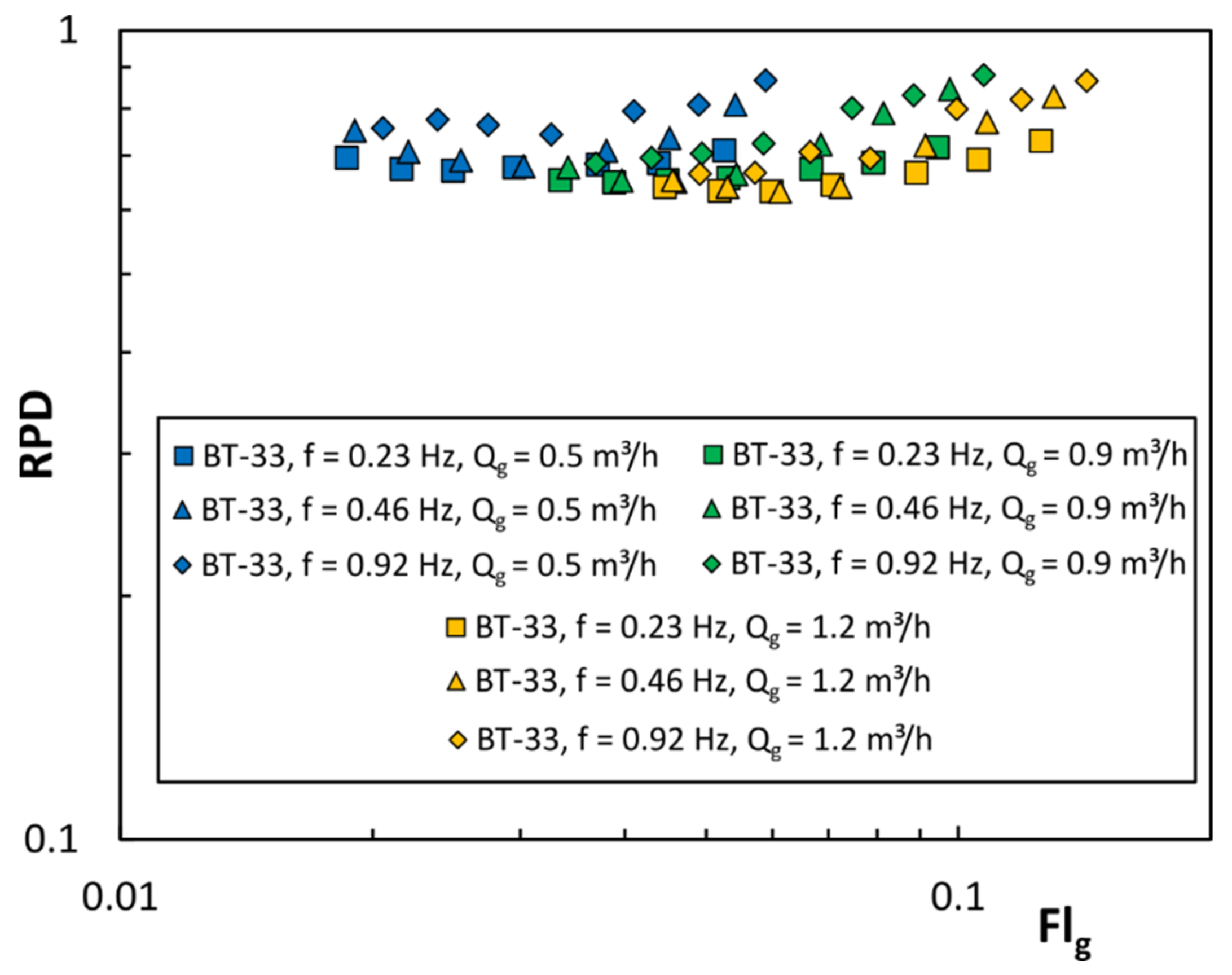
3.1.2. Gas-Liquid Mixing

Figure 4 shows the dependence of the relative power demand, RPD, on the gas flow number for the BT-33 impeller and unsteady mixing. Relative power is defined as the ratio of the mixing power in the gassed system, Pg, to the mixing power in the system without gas Pu (RPD = Pg/Pu), and the gas flow number, Fl g , is defined by the formula:
Fl g = Q g ND 3
The tests were carried out at a constant gas flow rate (Qg = const).
During the mixing of gas-liquid systems, a decrease in mixing power is observed. This is due to the decrease in density, as well as the accumulation of gas behind the impeller blades, the so-called gas caverns. Relative power demand depends not only on the amount of gas supplied but also on the oscillation frequency. Previous studies [23,24] for RT, BT-4, BT-6, and BT-33 impellers indicate that the RPD increases with increasing oscillation frequency. The influence of the number of blades and their shape are observed. Increasing the number of blades from four (BT-4) to six (BT-6) reduced the oscillation frequency impact. The same applies to the shape of the blade. The use of an ellipsoidal closed blade also reduces the influence of the oscillation frequency [23].
Relative power is an important parameter to determine the amount of energy dissipated in the stirred vessel and the efficiency of mass transfer. From the point of the latter, it is advisable to use impellers that are characterized by high relative power in the range of the gas flow number Flg of interest. Therefore, considering the RPD, it is advisable to use impellers with curved blades, for which the minimum relative power is about 0.65. In the case of the straight blade (RT) impellers, the power drop is approximately 50%.

3.2. Gas Hold-Up

The gas content in the mixture, also called the gas hold-up, is one of the most important parameters describing the mixing of gas-liquid systems. The amount of gas hold-up εg allows for assessing the dispersion capacity of the impeller. During unsteady mixing, the gas hold-up changes with time due to changes in the direction and impeller speed.
The concave/convex shape of the blade results in the fact that the amount of the energy dissipated depends on the direction of rotation. As a result, two characteristic values of the gas hold-up rate can be distinguished: the maximum value, εgmax, for the stage of changes in the impeller rotation frequency, during which it can operate as the concave blade; and minimum value, εgmin, where it operates as the convex blade impeller in the same oscillation period. The gas hold-up depends on the unsteady mixing power, i.e., the oscillation frequency of the impeller. Figure 5 shows the dependence of the gas hold-up εgmax on the gassed mixing power input per unit volume Pg/V.
The gas hold-up for unsteady mixing increases with the mixing power, as well as the gas flow rate Qg. The lowest hold-up values were observed for the BT-33 impeller, while for the BT-4 and BT-6 impellers they were comparable. A slight influence of the oscillation frequency was also observed, with its increase, a slight increase in the gas hold-up is observed. Moreover, as the amount of gas increased, the differences in the gas hold-up between the impellers decreased, with the lowest values observed for the BT-33 impeller. Figure 5 also compares the results obtained for the unsteady mixing with the results of the gas hold-up for the steady mixing and the A315, PBT, RT, and BT-6 impellers [28,29,30,31]. The obtained results show that for the unsteady mixing the rate of gas hold-up is greater than for the steady mixing. Moreover, as the energy input per unit volume increases, the differences in the gas hold-up decrease, and above 1000 W/m3, for the analyzed impellers, the gas hold-up for unsteady mixing is lower than for the steady mixing in a vessel equipped with the Rushton turbine and the BT-6 impeller [28,29,30,31]. In the case of the A315 and PBT impellers, the advantage of unsteady mixing disappears above Pg/V = 700 W/m3.
For the obtained dependences of the gas hold-up rate, the correlation equations of the general form were proposed:
ε g = C 1 P g V C 2 v g C 3   KC C 4
where C1, C2, C3, C4 are constants (Table 2) and KC is Keaulegan-Carpenter number.
KC = N max f
The Keulegan-Carpenter number is useful to consider the effect of the oscillation frequency, as well as to determine the ranges of the inertia force and drag effect [32]. For KC > 15, the drag force is dominant, while for KC < 4, the inertia force is the dominant one.
Equation (7) is valid in the following ranges: Pg/V ε (10; 1000) W/m3, vg ε < 0.0021; 0.005 > m/s and KC ε (4; 130).
In the case of the BT-33 impeller, a greater influence of the amount of gas is observed than in the case of the BT-4 and BT-6 impellers. This may indicate that when the blades are arranged in a concave-convex blade configuration, the gas caverns forming in the space between the blades have a greater influence. In the case of the BT-4 and BT-6 impellers, the effect is comparable and the constant C3 varies in the range from 0.412 to 0.439. Similarly, in the case of oscillation frequencies, a greater influence is observed for the BT-33 than for the BT-4 and BT-6.
In the case of the influence of the mixing power, the constant C2 varies in the range from 0.111 to 0.167 and is smaller compared to the steady mixing, for which C2 varies in the range from 0.2 to 0.63, and C3 in the range from 0.265 to 1.95 [17,28,29,30,33,34,35].
Unsteady mixing shows less dependence on Pg/V for concave impellers. The reason for this is the variability of the gas hold-up and dispersion states over time.

3.3. Volumetric Mass Transfer Coefficient KLa

The volumetric mass transfer coefficient, according to Higbi’s [36] theory, depends on the contact time between phases t, the diffusion coefficient in the liquid phase DL, and the interfacial area a:
k L a = 4 D L π t a
Calderbank [37] proposed a relationship that allows for determining the interfacial area based on the gassed power input per unit volume Pg/V, physicochemical parameters of fluids, and gas flow velocities vg:
a = 1.44 P g V 0.4 ρ c 0.2 σ 0.6 v g v t 0.5
where ρc, σ, vt are the density of the continuous phase, the interfacial tension, and the terminal velocity of raising up gas bubble, respectively.
It follows that the volumetric mass transfer coefficient can also be presented in the form of a dependence on the Pg/V and the superficial gas flow velocity.
Substituting Equation (10) into Equation (9) we obtain:
k L a = 1.44 4 D L π t P g V 0.4 ρ c 0.2 σ 0.6 v g v gr 0.5
Figure 6 shows the dependence of kLa on the superficial gas flow velocity vg for the analyzed impellers and different oscillation frequencies, as well as maximum impeller speed Nmax. For Nmax = 5 1/s, the values of the volumetric mass transfer coefficient kLa were comparable for all impellers, regardless of the gas flow velocity vg. Larger differences are observed for Nmax = 14 1/s. The highest efficiency of mass transfer is observed for the RT impeller and the lowest for the BT-33 impeller. With an increase in the oscillation frequency, it was observed that the advantage of Rushton’s turbine decreased with increasing gas velocity vg. This suggests that for gas flow velocities greater than vg = 0.0058 m/s or greater oscillation frequency, the impellers with ellipsoidal blades (BT-4 or BT-6) will show higher mass transfer efficiency. The differences between the impellers also result from the fact that at vg = const each impeller has a different gassed mixing power and RPD.
Figure 7 shows the dependence of kLa on Pg/V for various gas flow rates (0.5–1.2 m3/h).
The kLa coefficient grows exponentially with the increase of the gassed power input per unit volume Pg/V, as does the gas hold-up rate. The increase in kLa coefficient is related to the decrease in the Sauter diameter of the gas bubble d32, and, thus, the increase in the interfacial area a. With the increase in the amount of gas fed to the stirred vessel, kLa increases, which is related to the increase in the number of air bubbles and interfacial area. The obtained dependences of the volumetric mass transfer coefficient on the Pg/V and superficial gas velocity were subjected to statistical analysis in order to obtain the correlation equation. The nonlinear estimation method with the Levenberg-Marquardt algorithm was used. Additionally, the significance of differences was analyzed to determine the number of correlations. The results of the statistical analysis show that for all impellers and types of unsteady mixing, one correlation can be proposed:
k L a = C 5 P g V C 6 v g C 7
Table 3 summarizes the constant in Equation (12). The verification of the equation is shown in Figure 8.
Equation (12) is valid in the following ranges: Pg/V ε (10; 1100) W/m3, vg ε < 0.0021; 0.005 > m/s and KC ε (4; 130)
According to the Kolmogorov theory [38], for steady mixing, the constant C6 is 0.4, and the constant C7 is about 0.5. The obtained value of the constant C6 indicates compliance with the theory, and it is correct when the average size of the gas bubbles are only affected by their break-up [39]. The constant C7 of Equation (12) is smaller than the theoretical value. However, the literature analysis shows that both constants are variable. The constant C7 can vary in the range from 0.12 to 0.79 [27,28,33,39].
Figure 7 also shows a comparison of the obtained kLa values for unsteady mixing with the values for steady mixing and the RT and BT-6 impellers [28,31]. The comparison shows that the mass transfer efficiency for the unsteady mixing in the RT, BT-6, BT-4, and BT-33 impellers is greater than for the steady mixing. This indicates a lower impact of gas caverns on the decrease in mixing power, which is caused by their instability due to the unsteady rotation of the impeller [7].

4. Conclusions

The purpose of mixing of two-phase systems is to increase the interfacial area and to improve the mass transfer. This is done using impellers with concave blades, which limit the size of the gas caverns. In unsteady mixing, the impeller performs a rotating, oscillating motion, as a result of which, the impeller can operate as a convex blade impeller and concave blade impeller at the same oscillation period.
This paper presents the results of research into the gas hold-up and the volumetric mass transfer coefficient for turbine impellers with ellipsoidal asymmetric blades (BT-6 and BT-4), and six alternately arranged (BT-33). The tests confirmed that for mixing, the gas hold-up increases with the increase in the gassed power input per unit volume. The lowest values of the gas hold-up are obtained when the ellipsoidal blades are arranged alternately (BT-33). On the other hand, for an impeller with four or six blades, the gas hold-up is similar. Such results are surprising, because in steady mixing an impeller with more blades could disperse more gas. This opens new research opportunities. A slight influence of the oscillation frequency of the impeller is also observed: as the oscillation frequency increases, the rate of gas hold-up increases.
Mass transfer coefficient is strongly dependent on power input per unit volume and superficial gas flow velocity. Impellers with flat blades, such as the Rushton turbine, have the largest power demand and in unsteady mixing give the highest values of kLa. The results showed that for concave impellers the effect of superficial gas flow velocity is relevant and above vg = 0.005 m/s kLa could be greater in comparison to the Rushton turbine. This requires further investigation.
Overall, these results suggest that unsteady mixing in an unbaffled vessel could be an alternative to steady mixing in baffled vessels. The use of concave impellers improves mass transfer in comparison to a steady rotating Rushton turbine or BT-6 impeller. Future research is needed to investigate the effect of the number of blades and the blade height.

Author Contributions

Conceptualization, S.W.; investigation, S.F. and S.W.; writing—original draft preparation, S.W. and S.F.; writing—review and editing, S.W. and S.F.; supervision, S.W. All authors have read and agreed to the published version of the manuscript.

Funding

This research was funded by the Ministry of Education and Science of Poland.

Conflicts of Interest

The authors declare no conflict of interest.

Nomenclature

ainterfacial area per volume unit, (m2/m3)
Cimpeller bottom clearance, (m)
coxygen concentration, (mg/L)
CDdrag coefficient
CIinertia coefficient
Dimpeller diameter, (m)
DLdiffusion coefficient in the liquid phase
Dsring sparger diameter, (m)
DVvessel diameter, (m)
Flggas flow number, Flg = Qg/(ND3ρ)
foscillation frequency, (Hz)
HLliquid height, (m)
KCKeaulegan-Carpenter number
kLavolumetric mass transfer coefficient, (s−1)
Nimpeller speed, (s−1)
Pmixing power, (W)
Popower number, Po = P/(N3D5ρ)
Qflow rate, (m3s−1)
ReReynolds number, Re = ND2ρ/η
RPDrelative power demand, RPD = Pg/Pu
Ttemperature, (°C)
TStorque, (Nm)
ttime, (s)
Vvolume, (m3)
vvelocity, (m/s)
Greek letters
εggas hold-up
ρdensity, (kg m−3)
σinterfacial tension, (Nm−1)
ωangular frequency, (rad s−1)
Subscripts
maxmaximum
minminimum
tinstantaneous
*equilibrium
0initial
ggassed conditions
uungassed conditions
ccontinuous phase

References

  1. Ni, X.; Mackley, M.R.; Harvey, A.P.; Stonestreet, P.; Baird, M.H.I.; Rama Rao, N.V. Mixing through oscillations and pulsations—a guide to achieving process enhancements in the chemical and process industries. Chem. Eng. Res. Des. 2003, 81, 373–383. [Google Scholar] [CrossRef]
  2. Ni, X.; Gao, S. Scale-up correlation for mass transfer coefficients in pulsed baffled reactors. Chem. Eng. J. Biochem. Eng. J. 1996, 63, 157–166. [Google Scholar] [CrossRef]
  3. Ni, X.; Gao, S.; Cumming, R.H.; Pritchard, D.W. A comparative study of mass transfer in yeast for a batch pulsed baffled bioreactor and a stirred tank fermenter. Chem. Eng. Sci. 1995, 50, 2127–2136. [Google Scholar] [CrossRef]
  4. Yoshida, M.; Taguchi, Y.; Yamagiwa, K.; Ohkawa, A.; Abe, M.; Tezura, S.; Shimazaki, M. Design and operation of unbaffled aerated agitated vessels with unsteadily forward-reverse rotating impellers handling viscous Newtonian liquids. J. Chem. Technol. Biotechnol. 2003, 78, 474–483. [Google Scholar] [CrossRef]
  5. Yoshida, M.; Kimura, A.; Yoneyama, A.; Tezura, S. Design and operation of unbaffled vessels agitated with an unsteadily forward–reverse rotating impeller handling solid–liquid dispersions. Asia-Pac. J. Chem. Eng. 2012, 7, 572–580. [Google Scholar] [CrossRef]
  6. Yoshida, M.; Watanabe, M.; Yamagiwa, K.; Ohkawa, A.; Abe, M.; Tezura, S.; Shimazaki, M. Behaviour of gas-liquid mixtures in an unbaffled reactor with unsteadily forward-reverse rotating impellers. J. Chem. Technol. Biotechnol. 2002, 77, 678–684. [Google Scholar] [CrossRef]
  7. Yoshida, M.; Akiho, M.; Nonaka, H.; Yamagiwa, K.; Ohkawa, A.; Tezura, S. Mixing and mass transfer characteristics of an unbaffled aerated agitation vessel with unsteadily forward-reverse rotating multiple impellers. Lat. Am. Appl. Res. 2005, 35, 37–42. [Google Scholar]
  8. Woziwodzki, S. Unsteady mixing characteristics in a vessel with forward-reverse rotating impeller. Chem. Eng. Technol. 2011, 34, 767–774. [Google Scholar] [CrossRef]
  9. Takahashi, K.; Takahata, Y.; Kurisaka, K.; Sekine, H. Mixing performance experiments in an agitated vessel equipped with a pitched paddle subjected to unsteady agitation. J. Chem. Eng. Jpn. 2011, 44, 852–858. [Google Scholar] [CrossRef]
  10. Kato, Y.; Tada, Y.; Ban, M.; Nagatsu, Y.; Iwata, S.; Yanagimoto, K. Improvement of mixing efficiencies of conventional impeller with unsteady speed in an impeller revolution. J. Chem. Eng. Jpn. 2005, 38, 688–691. [Google Scholar] [CrossRef] [Green Version]
  11. Yoshida, M.; Shigeyama, M.; Hiura, T.; Yamagiwa, K.; Ohkawa, A.; Tezura, S. Liquid-Phase Mixing in an Unbaffled Agitated Vessel with an Unsteady Forward-Reverse Rotating Impeller. Asia-Pac. J. Chem. Eng. 2007, 2, 659–664. [Google Scholar] [CrossRef]
  12. Yoshida, M.; Wakura, Y.; Yamagiwa, K.; Ohkawa, A.; Tezura, S. Liquid Flow Circulating within an Unbaffled Vessel Agitated with an Unsteady Forward-Reverse Rotating Impeller. J. Chem. Technol. Biotechnol. 2010, 85, 1017–1022. [Google Scholar] [CrossRef]
  13. Yoshida, M.; Taguchi, Y.; Yamagiwa, K.; Ohkawa, A.; Abe, M.; Tezura, S.; Shimazaki, M. Mixing Characteristics of Liquid Phase in an Unbaffled Vessel Agitated by Unsteadily Forward-Reverse Rotating Multiple Impellers. Lat. Am. Appl. Res. 2004, 34, 35–40. [Google Scholar]
  14. Yoshida, M.; Nagai, Y.; Yamagiwa, K.; Ohkawa, A.; Tezura, S. Turbulent and Laminar Mixings in an Unbaffled Agitated Vessel with an Unsteadily Angularly Oscillating Impeller. Ind. Eng. Chem. Res. 2009, 48, 1665–1672. [Google Scholar] [CrossRef]
  15. Woziwodzki, S. Mixing of Viscous Newtonian Fluids in a Vessel Equipped with Steady and Unsteady Rotating Dual-Turbine Impellers. Chem. Eng. Res. Des. 2014, 92, 435–446. [Google Scholar] [CrossRef]
  16. Woziwodzki, S.; Broniarz-Press, L. Mixing of Shear-Thinning Fluid with Yield Stress in a Vessel with Unsteadily Rotating Impeller. In Proceedings of the 14th European Conference on Mixing, Warsaw, Poland, 10 September 2012; pp. 515–521. [Google Scholar]
  17. Middleton, J.C.; Smith, J.M. Gas-liquid mixing in turbulent systems. In Handbook of Industrial Mixing. Science and Practice; Paul, E.L., Atiemo-Obeng, V., Kresta, S.M., Eds.; John Wiley & Sons: Hoboken, NJ, USA, 2004; pp. 585–635. [Google Scholar]
  18. Yoshida, M.; Kitamura, A.; Yamagiwa, K.; Ohkawa, A. Gas hold-up and volumetric oxygen transfer coefficient in an aerated agitated vessel without baffles having forward-reverse rotating impellers. Can. J. Chem. Eng. 1996, 74, 31–39. [Google Scholar] [CrossRef]
  19. Yoshida, M.; Yamagiwa, K.; Ohkawa, A.; Takahashi, K.; Shimazaki, M.; Abe, M. Torque of drive shaft with unsteadily rotating impellers in an unbaffled aerated agitation vessel. Mater. Technol. 1999, 17, 19–31. [Google Scholar]
  20. Yoshida, M.; Ito, A.; Yamagiwa, K.; Ohkawa, A.; Abe, M.; Tezura, S.; Shimazaki, M. Power characteristics of unsteadily forward-reverse rotating impellers in an unbaffled aerated agitated vessel. J. Chem. Technol. Biotechnol. 2001, 76, 383–392. [Google Scholar] [CrossRef]
  21. Yoshida, M.; Yamagiwa, K.; Ito, A.; Ohkawa, A.; Abe, M.; Tezura, S.; Shimazaki, M. Flow and mass transfer in aerated viscous Newtonian liquids in an unbaffled agitated vessel having alternating forward-reverse rotating impellers. J. Chem. Technol. Biotechnol. 2001, 76, 1185–1193. [Google Scholar] [CrossRef]
  22. Woziwodzki, S.; Broniarz-Press, L. Power characteristics of unsteadily rotating rushton turbine in aerated vessel. Tech. Trans. 2014, 2-Ch, 155–164. [Google Scholar]
  23. Frankiewicz, S.; Woziwodzki, S. Effect of Blade Shape on Unsteady Mixing of Gas-Liquid Systems. In Practical Aspects of Chemical Engineering; Lecture Notes on Multidisciplinary Industrial Engineering; Springer: Cham, Switzerland, 2018; pp. 127–136. ISBN 978-3-319-73977-9. [Google Scholar]
  24. Frankiewicz, S.S.; Woziwodzki, S. Gas-Liquid Mixing in an Unbaffled Vessel with a Forward-Reverse Rotating Scaba Impeller. In Practical Aspects of Chemical Engineering; Ochowiak, M., Woziwodzki, S., Mitkowski, P.T., Doligalski, M., Eds.; Springer International Publishing: Cham, Switzerland, 2020; pp. 79–88. ISBN 978-3-030-39867-5. [Google Scholar]
  25. Woziwodzki, S. Application of Morison Equation in Unsteady Mixing Characteristics. In Practical Aspects of Chemical Engineering; Ochowiak, M., Woziwodzki, S., Mitkowski, P.T., Doligalski, M., Eds.; Springer International Publishing: Cham, Switzerland, 2020; pp. 491–499. ISBN 978-3-030-39867-5. [Google Scholar]
  26. Bouaifi, M.; Roustan, M. Bubble size and mass transfer coefficients in dual-impeller agitated reactors. Can. J. Chem. Eng. 1998, 76, 390–397. [Google Scholar] [CrossRef]
  27. Kiełbus-Rąpała, A.; Karcz, J. Mass transfer in multiphase mechanically agitated systems. In Mass Transfer in Multiphase Systems and Its Applications; El-Amin, M., Ed.; InTech: London, UK, 2011; ISBN 978-953-307-215-9. [Google Scholar]
  28. Van’t Riet, K. Review of measuring methods and results in nonviscous gas-liquid mass transfer in stirred vessels. Ind. Eng. Chem. Process. Des. Dev. 1979, 18, 357–364. [Google Scholar] [CrossRef]
  29. Bakker, A. Hydrodynamics of Stirred Gas-Liquid Dispersions; Technische Univesiteit Delft: Delft, The Netherlands, 1992. [Google Scholar]
  30. Chapman, C.M.; Nienow, A.W.; Cooke, M.; Middleton, J.C. Particle-gas-liquid mixing in stirred vessels. Part II: Gas-liquid mixing. Chem. Eng. Res. Des. 1983, 61, 82–95. [Google Scholar]
  31. Zheng, Z.; Sun, D.; Li, J.; Zhan, X.; Gao, M. Improving oxygen transfer efficiency by developing a novel energy-saving impeller. Chem. Eng. Res. Des. 2018, 130, 199–207. [Google Scholar] [CrossRef]
  32. Sarpkaya, T. Wave Forces on Offshore Structures; Cambridge University Press: Cambridge, NY, USA, 2010. [Google Scholar]
  33. Jesus, S.S.; Santana, A.; Filho, R.M. Hydrodynamic and mass transfer study in a mechanically stirred hybrid airlift bioreactor based on impeller type. Int. J. Chem. Eng. Appl. 2014, 5, 41–45. [Google Scholar] [CrossRef] [Green Version]
  34. Vasconcelos, J.M.T.; Orvalho, S.C.P.; Rodriguez, A.M.A.F.; Alvez, S.S. Effect of blade shape on the performance of six-bladed disk turbine impellers. Ind. Eng. Chem. Res. 2000, 39, 203–213. [Google Scholar] [CrossRef]
  35. Woziwodzki, S.; Broniarz-Press, L.; Radecki, R. Mieszanie układów ciecz-gaz w mieszalniku z mieszadłem A310 wykonującym ruch nieustalony. Inż. Apar. Chem. 2015, 54, 364–365. [Google Scholar]
  36. Higbie, R. The Rate of Absorption of a Pure Gas into a Still Liquid during Short Periods of Exposure. Trans. AIChE 1935, 31, 365–389. [Google Scholar]
  37. Calderbank, P.H. Physical rate processes in industrial fermentation. Part I: The interfacial area in gas-liquid contacting with mechanical agitation. Chem. Eng. Res. Des. 1958, 36, 443–463. [Google Scholar]
  38. Kolmogorov, A.N. On the Disintegration of Drops in a Turbulent Flow. Dokl. Akad. Nauk SSSR 1949, 66, 825–828. [Google Scholar]
  39. Martín, M.; Montes, F.J.; Galán, M.A. Physical explanation of the empirical coefficients of gas-liquid mass transfer equations. Chem. Eng. Sci. 2009, 64, 410–425. [Google Scholar] [CrossRef]
Figure 1. Experimental set-up.
Energies 15 00346 g001
Figure 2. Impellers (a) Rushton turbine (RT) (b) BT-6 (c) BT-33 (d) BT-4.
Energies 15 00346 g002
Figure 3. Power requirements for RT, BT-6, BT-33, and BT-4 impellers, (a) steady mixing (b) unsteady mixing.
Energies 15 00346 g003
Figure 4. Relation between the relative power demand, RPD, and gas flow number, Flg, for unsteady mixing.
Energies 15 00346 g004
Figure 5. Relation between gas hold-up and Pg/V for BT-33, BT-4, and BT-6 impellers: (a) vg = 0.0021 m/s, Qg = 0.5 m3/h; (b) vg = 0.0038 m/s, Qg = 0.9 m3/h; (c) vg = 0.005 m/s, Qg = 1.2 m3/h.
Energies 15 00346 g005
Figure 6. Relation between volumetric mass transfer coefficient kLa and superficial gas velocity vg for BT-33, BT-4, BT-6, and RT impellers: (a) f = 0.23 Hz, (b) f = 0.46 Hz, (c) f = 0.92 Hz.
Energies 15 00346 g006
Figure 7. Relation between volumetric mass transfer coefficient kLa and Pg/V for BT-33, BT-4, BT-6, and RT impellers.
Energies 15 00346 g007
Figure 8. Verification of Equation (12): (a) experimental data and model, (b) predicted and observed values of kLa.
Energies 15 00346 g008
Table 1. Summary of research into the unsteady gas-liquid mixing.
AuthorSystemImpellerCourseScope
Yoshida et al. [18]air-waterdelta AJITERsinusoidalgas hold-up mass transfer
Yoshida et al. [19]air-waterdelta AJITERsinusoidalpower requirements gas hold-up mass transfer mixing time
Yoshida et al. [20,21]air-millet jellydelta AJITERsinusoidalpower requirements gas hold-up mass transfer
Yoshida et al. [6,7]air-waterRushton turbine deltasinusoidalpower requirements mixing time
Yoshida et al. [4]air-ethanol
air-glycerol
air-millet jelly
delta AJITERsinusoidalpower requirements gas hold-up mass transfer
Woziwodzki and Broniarz-Press [22]air-waterRuhton turbine PBTtriangle with/without change of direction of rotationpower requirements
Frankiewicz and Woziwodzki [23,24]air-waterBT-6, BT-4, BT-4E Scaba 6SRGTtrianglepower requirements
Table 2. Constants in Equation (7).
ImpellerC1C2C3C4R2
BT-330.4320.1670.621−0.1080.729
BT-4 0.1560.1360.412−0.0290.931
BT-60.2040.1110.439−0.0350.918
Table 3. Constants in Equation (12).
ImpellerC5C6C7R2
BT-33, BT-4, BT-6, RT0.020.4080.4310.941
Publisher’s Note: MDPI stays neutral with regard to jurisdictional claims in published maps and institutional affiliations.

