Article

The Effect of Dynamic Cold Storage Packed Bed on Liquid Air Energy Storage in an Experiment Scale

1
School of Energy & Environment, Southeast University, Nanjing 210096, China
2
Shenzhen Energy Nanjing Holding Co., Ltd., Nanjing 210000, China
3
Xinglu Air Separation Ltd., Suzhou 215131, China
*
Author to whom correspondence should be addressed.
These authors contributed equally to this work and should be regarded as co-first authors.
Energies 2022, 15(1), 36; https://doi.org/10.3390/en15010036
Submission received: 15 November 2021 / Revised: 8 December 2021 / Accepted: 15 December 2021 / Published: 21 December 2021
(This article belongs to the Section D: Energy Storage and Application)

Abstract

:
Liquid air energy storage (LAES) is one of the most promising large-scale energy storage technologies for the decarburization of networks. When electricity is needed, the liquid air is utilized to generate electricity through expansion, while the cold energy from liquid air evaporation is stored and recovered in the air liquefaction process. The packed bed filled with rocks/pebbles for cold storage is more suitable for real-world application in the near future compared to the fluids for cold storage. A standalone LAES system with packed bed energy storage is proposed in our previous work. However, the utilization of pressurized air for heat transfer fluid in the cold storage packed bed (CSPB) is confusing, and the effect of the CSPB on the system level should be further discussed. To address these issues, the dynamic performance of the CSPB is analyzed with the physical properties of the selected cold storage materials characterized. The system simulation is conducted in an experiment scale with and without considering the exergy loss of the CSPB for comparison. The simulation results show that the proposed LAES system has an ideal round trip efficiency (RTE) of 39.38–52.91%. With the consideration of exergy destruction of the CSPB, the RTE decreases by 19.91%. Furthermore, increasing the cold storage pressure reasonably is beneficial to the exergy efficiency of the CSPB, whether it is non-supercritical (0.1 MPa–3 MPa) or supercritical (4 MPa–9 MPa) air. These findings will give guidance and prediction to the experiments of the LAES and finally promote the development of the industrial application.

1. Introduction

To combat climate change, the demand for renewable energy sources still increased in 2020 under the effect of COVID-19, while the consumption of fossil energy sources declined. Between 2021 and 2022, renewable energy expansion accounted for 90 percent of global electricity expansion [1,2]. However, renewable energy is intermittent, and their power generation, when connected to electric networks, will threaten the stability and security of the grid [3,4]. Energy storage technologies can solve this problem. Thermal energy storage is greatly used in people’s lives, and phase change materials are popular in recent years, employed in many commercial applications where stable temperatures are required [5,6]. The potential market of phase change materials includes building heating/cooling [7], heatsink [8], clothing [9], etc. Among large-scale electricity storage, pumped hydro energy storage is the most developed technology with a high efficiency of 65–80%. However, pumped hydro energy storage, along with compressed air energy storage, has geographical constraints and is unfriendly to the environment. Liquid air energy storage (LAES) is another large-scale mechanical energy storage technology, which also belongs to thermal energy storage. It has attracted extensive attention over the years due to several significant advantages such as no geographical constraints, friendly energy storage materials, high energy storage density, etc. [10].
The LAES system consists of three processes: a charging process, a discharging process, and a storage process (shown in Figure 1). In the charging process, the purified air is compressed and liquefied by renewable energy or off-peak electricity, whereas the compression heat is stored; in the discharging process, liquid air is pumped and expanded to produce peak electricity, whereas the cold energy from liquid air evaporation is used to enhance air liquefaction. Cold recovery and storage are crucial to the LAES system. A great number of researchers, therefore, focus on efficient cold recovery methods to improve the thermodynamic performance of LAES.

1.1. Development of Cold Recovery for LAES System

At the beginning of Smith’s patent [12], the ‘cold regenerator’ made of stainless steel was first invented and employed as the role of the cold recovery component. This regenerator was also used to recover the cold energy of liquid air in the work of Chino and Araki [13], which is composed of steel pipes filled with small pebbles. Subsequently, the rocks/pebbles were naturally utilized as the cold storage materials for the cold recovery process of the LAES system, mainly due to their low capital costs and good chemical stability. Based on the first pilot plant (350 kW/2.5 MWh) located at the University of Birmingham, Morgan et al. [14] predicted a high RTE of ~60% with high-grade heat contribution from CHP plants. Sciacovelli et al. [15] established a dynamic model of the cold storage packed bed (CSPB) filled with rocks for the LAES system, achieving a round trip efficiency (RTE) of ~50% with the compression heat recovery by thermal oil. This led to a trend of the CSPB employed in LAES systems. Using the same LAES models, Legrand et al. [16] introduced the LAES system to the Spanish power grid with renewables connected, of which the leveled cost of energy and storage were significantly reduced. Vecchi et al. [17] assessed a realistic LAES model considering off-design conditions for participating in electricity markets, and the RTE can be different by up to 30%. Due to the inevitable dynamic performance of LAES caused by the thermoclines in their CSPB, Wang et al. [18] proposed two operation modes for the air liquefaction process to smooth the dynamic effects, resulting in a low RTE of ~43%. The pressurized air was employed as the heat transfer fluid for cold recovery; however, the reason was not elaborated.
Another cold recovery method is fluid-based cold storage, which is not only employed as cold storage material but also as heat transfer fluid. The fluids for cold storage mainly include methanol/propane [19,20,21,22,23,24] and propane [25,26]. Li et al. [19] used a combination of methanol and propane as cold storage materials for the first time and obtained good temperature gradient matching in heat exchange. The RTE can be achieved at a high value of 71% when integrated with the nuclear power plant. She et al. [20] proposed a LAES system with an Organic Rankine Cycle for effective compression heat recovery and utilization. The RTE was increased to ~55%. This system configuration with liquid methanol/propane for cold storageencourages many LAES scholarstoinvestigate the efficient use of compression heat, mainly including additional power generation [21,22] and cooling/heating [23,24].Compared to the rocks/pebbles for cold storage, liquids for cold storage usually result in a higher RTE. However, the LAES systems with fluid-based cold storage are generally steady-state and simplified without considering the energy loss during charging, storage, and discharging processes. Moreover, these cold storage fluids are flammable, which is dangerous when the LAES is applied in large-scale power plants and networks.

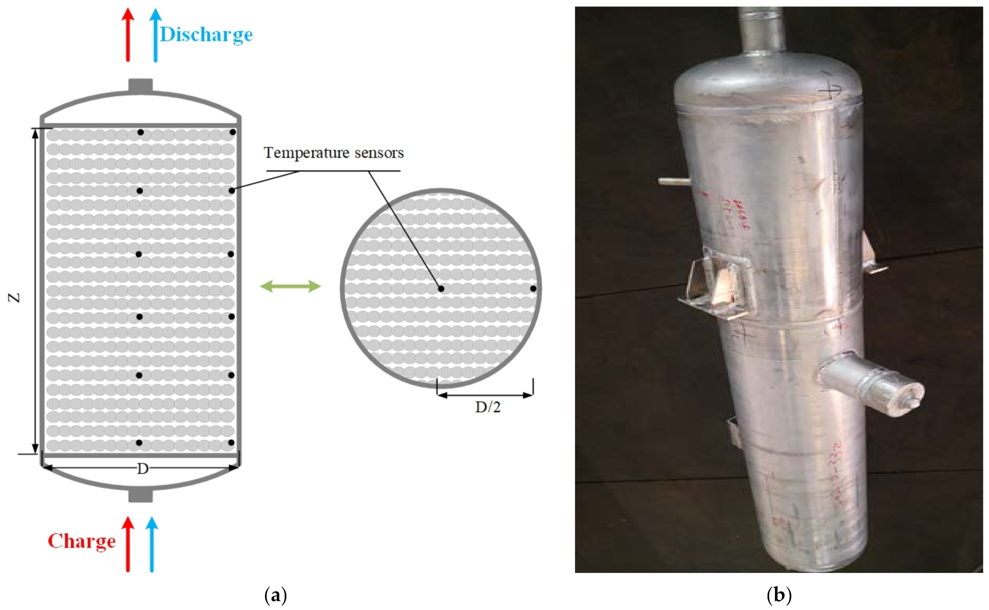
1.2. Development of Experimental Packed Bed

The LAES has a history of ~50 years since 1977 when Smith [12] proposed using liquid air for peak shaving. The amount of LAES research increases year by year, especially after 2010 with the first LAES pilot plant built. However, minimal literature was related to experiments, which is not conducive to the LAES for industrial applications. There is no available experimental data on cold storage in the literature.
Packed bed energy storage is a mature thermal energy storage technology used as both heat and cold storage of the LAES system. The experiments were generally conducted in the high-temperature range of over 300 K. Wen et al. [27] studied experimentally the transient and steady-state heat transfer behaviors of fluid flowing through the packed bed in the temperature difference range of 100 °C, which found that the temperature drop at the wall of the packed bed depended on the distance from the inlet. Liu et al. [28] conducted experiments of the rock bed in the temperature range of over 150 K, which showed a higher pressure led to smaller radial temperature distribution, and less the inlet effect on the heat transfer coefficient. Besides, Chai et al. [29] tested the packed bed in a cryogenic energy storage system under the temperature from −200 °C to 40 °C, which found that the axial length of the thermocline zone increased as the working pressure decreased.

1.3. Objective and Motivation of This Study

In the LAES system, there are still some knowledge gaps about cold storage being indicated in the above literature review: (1) Our previous work, along with other studies, reports that the packed bed filled with rocks for cold storage is popular recently and promising for industrial applications; however, the utilization of pressurized air for heat transfer fluid in the CSPB is confusing; the reason needs to be further elaborated. (2) The effect of CSPB on the LAES system is not clear. (3) The above-mentioned LAES studies are mainly based on simulation analysis; LAES experiments are scarce and are not conducive for future development; in order to guide and predict the experiments of the CSPB in the LAES system, the thermodynamic analysis of an experiment-scale CSPB should be conducted in advance.
To address the above issues, this study establishes a LAES model based on a standalone LAES configuration, which is reported in our previous work [18]. The physical properties of the selected white cobbles for cold storage were first characterized. The sensitive analysis of the cold storage pressure on the LAES system is studied in idealistic conditions. The dynamic performance of the experiment-scale CSPB in the LAES system is analyzed from the first cycle to the stable cycle. Finally, the liquid yield and RTE are evaluated for the experimental-scale LAES system. The main objective of this study is to investigate the effect of the dynamic CSPB on the LAES system. Section 1 shows the background, literature review, and motivation; Section 2 describes the methods and approaches, expounding on the mathematical model and validation; Section 3 presents the results and discussion; Section 4 gives the main conclusions.

2. Methods and Approaches

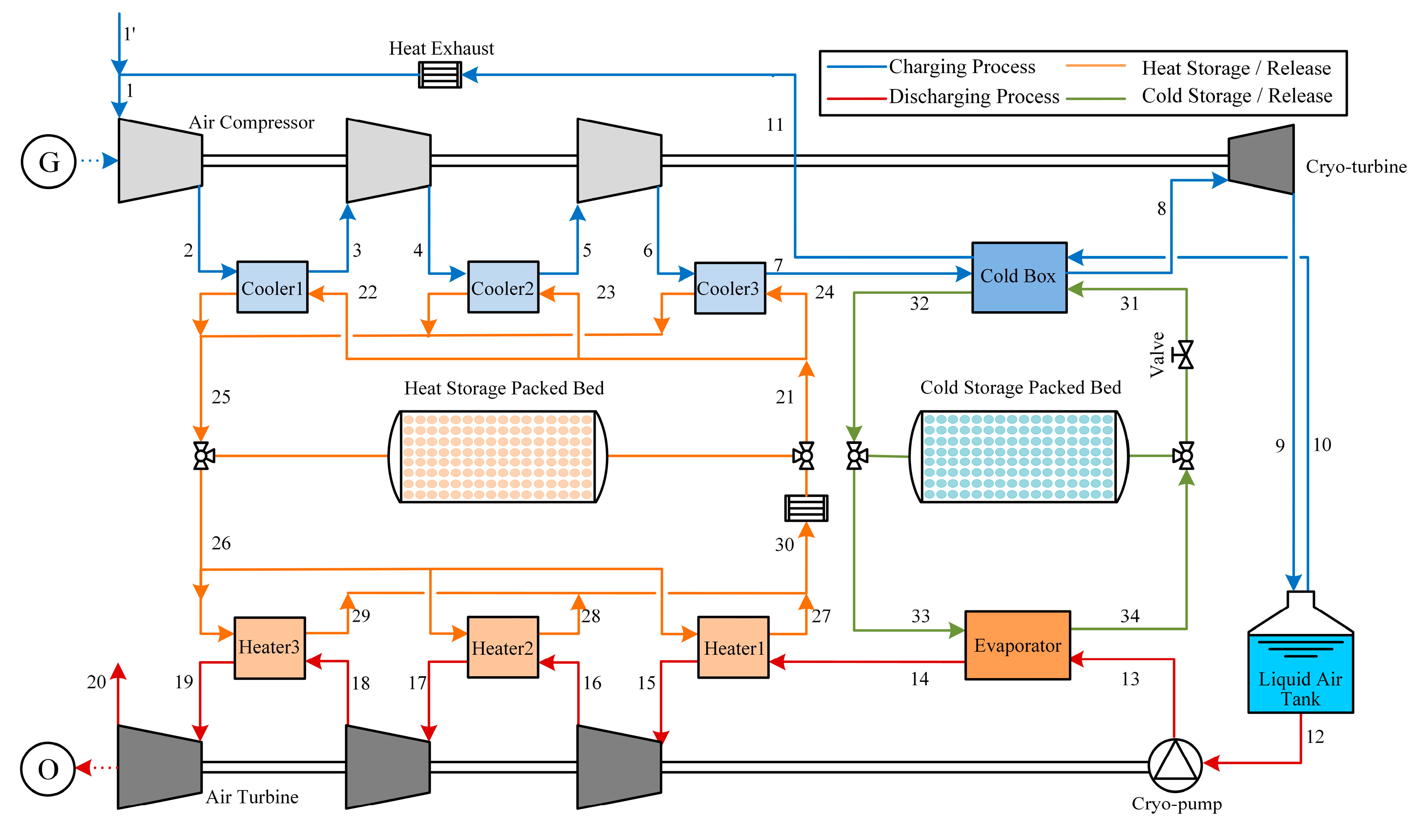
2.1. System Description

Figure 2 shows the specific flow figure of the proposed LAES system with packed bed energy storage. The system is mainly composed of an air liquefaction (i.e., charging) process based on a Linde cycle and a power generation (i.e., discharging) process based on an open-Rankine cycle. The detailed operation of the system is as follows.

2.1.1. Charging and Discharging Process of LAES System

When the electricity is excess (i.e., off-peak hours), the charging process operates to produce liquid air: the ambient air mixed with reflux air (point 1) is compressed and cooled by a three-stage air compressor with inter-coolers, the compression heat is harvested and stored in the heat storage packed bed (HSPB) by thermal oil (i.e., heat recovery fluid); the air after compression (point 7) is then deeply cooled down in the cold box by the reflux air and the pressurized air (i.e., cold recovery fluid) from the CSPB; the liquid air is finally generated through expansion, then stored in the tank.
When the electricity is needed (i.e., peak hours), the discharging process operates to generate power: the liquid air (point 12) is pumped by a cryo-pump and preheated in the evaporator, the cold energy of liquid air is harvested and stored in the CSPB by pressurized air; the high-pressure working air (point 14) is then furtherly heated and expanded by a three-stage air turbine with inter-heaters to produce electricity.

2.1.2. Charge and Discharge Process of the Packed Beds
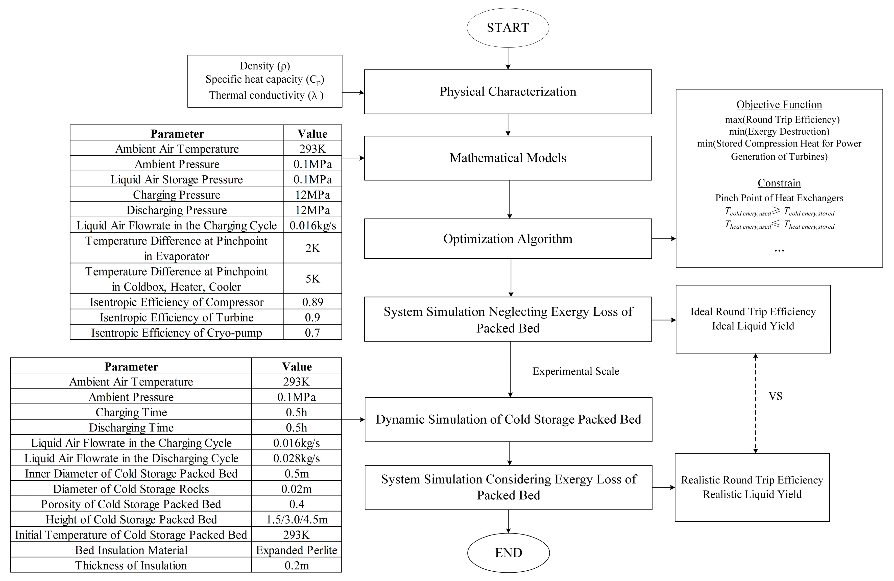
The packed bed is a cylindrical container filled with spherical particles. The container is made of a Q345R pressure vessel steel plate which is insulated by expanded perlite. The temperature sensors are arranged inside the particles to measure the temperature changes of bed layer by layer. The packed bed energy storage includes two processes: the charge (heat/cold storage) process and the discharge (heat/cold release) process, which is shown in Figure 3a.
In the charg process, the hot/cold stream flows from the bottom of the bed to the top, transferring heat/cold energy to the rocks; in the discharge process, the stream with ambient temperature flows from the top of the bed to the bottom, extracting the heat/cold energy from the rocks. The packed bed is filled with a kind of white cobble, which comes from Xinmao Mineral Products Processing Plant in China with a low price of 231.75 $/ton.
For the HSPB, the heat energy from air compression is sufficient for enhancing the power generation of air turbines, whereas the rest of the compression heat is exhausted for other occasions. The charge process of HSPB works in the charging process of the LAES system, and the discharge process of HSPB works in the discharging process of the LAES system.
For the CSPB, the cold energy from liquid air gasification is insufficient for enhancing the air liquefaction to the idealistic condition, which is further discussed in this study. The charge process of CSPB works in the discharging process of the LAES system, and the discharge process of CSPB works in the charging process of the LAES system. The picture of CSPB in an experimental scale can be found in Figure 3b.

2.2. Methodology

Figure 4 shows the methodology of this study, with the default working parameters. The mathematical models of the proposed LAES system are established in Matlab R2020a. In order to obtain high thermodynamic performance, the methodology performs a genetic algorithm to optimize parameters. The initial population is generated by default and the size of pulation is determined by the optimization variables. The judging codes are used to decide the end condition or not. After generations, the programme outputs the optimization results. The objective function based on the optimization algorithm is also shown in Figure 4.

2.3. Mathematical Model

2.3.1. Power Components and Heat Exchangers

For the compressors, turbines and pump, the outlet specific enthalpy can be expressed by:
h e i + 1 , c o m = h e i , c o m + h e i + 1 , c o m , s h e i , c o m η i s o , c o m h e i + 1 , t u r = h e i , t u r + η i s o , t u r h e i + 1 , t u r , s h e i , t u r h e i + 1 , p u m p = h e i , p u m p + h e i + 1 , p u m p , s h e i , p u m p η i s o , p u m p .  
where ηiso is the isentropic efficiency; subscript ‘i’ represents the stream number; subscript ‘s’ represents isentropic process; subscript ‘com’, ‘tur’ and ‘pump’ refer to compressor, turbine and cryo-pump, respectively. The power consumption of air compressor is hence given by:
W P C , A C = m 1 · h e 2 h e 1 + h e 4 h e 3 + h e 6 h e 5
where m is the mass flow rate. The power output of cryo-turbine (WPO,CT) and air turbine (WPO,AT) is respectively calculated by:
W P O , C T = m 8 · h e 8 h e 9
W P O , A T = m 15 · h e 15 h e 16 + h e 17 h e 18 + h e 19 h e 20
where the subscript ‘charging’ and ‘discharging’ respectively refer to the charging and discharging process of the LAES system.
The power consumption of cryo-pump is given by:
W P C , P u m p = m 12 · h e 13 h e 12
Finally, the net power input of the charging process and the net power output of the discharging process are determined by:
W P C , c h a r g i n g = W P C , A C W P O , C T
W P O , d i s c h a r g i n g = W P O , A T W P C , P u m p

2.3.2. Charge and Discharge Processes of Packed Bed

The HSPB and the CSPB use the same numerical model for simulation. As shown in Figure 3a, the numerical model of the packed bed is a cylindrical container filled with spherical particles. Some basic assumptions are as follows:
(1)
One-dimensional Newton heat transfer, ignoring the radial temperature gradient [30].
(2)
It is unidirectional for the fluid to flow in the bed, ignoring the viscous stress and kinetic energy terms.
(3)
The specific heat, density, and thermal conductivity of rocks change as the temperature changes; the viscosity, specific heat, density, and thermal conductivity of the fluid change with temperature.
(4)
Radiation heat transfer is ignored.
The continuous solid phase model [31,32] expressed the temperature equations of heat transfer fluid and solid particles in the packed bed. For the heat transfer fluids:
ε ρ f c p , f T f t + ε ρ f c p , f u f T f x = ε λ f 2 T f x 2 + 6 1 ε h d p T s T f + h w T w T f
For the solid particles [18]:
1 ε ρ s c p , s T s t = 1 ε λ s 2 T s x 2 + 6 1 ε h d p T f T s
where ε is the porosity of the packed bed, cp is the specific heat of the heat transfer fluids, u is the velocity of the packed bed, T is the temperature of the packed bed, t is the charge or discharge time, z is the axis of height, λ is the thermal conductivity of the heat transfer fluids or the solid particles, and dp is the particle diameter; subscripts ‘f’, ‘s’ and ‘w’ refer to the heat transfer fluid, solid particles, and wall, respectively.
The surface heat transfer coefficient h between heat transfer fluid and filled solid particles is computed by Wakao’ s formula [33]:
N u = h d p λ f = 2 + 1.1 P r 1 3 R e p 0.6
where Nu, Re, and Pr are the Nusselt number, Reynolds number, and Prandtl number, respectively; μ is the viscosity of the heat transfer fluids.
R e p = ρ f u f ε d p μ f ,   P r = c p , f μ f λ f
The volumetric heat transfer coefficient hw of the wall was computed by Incropera [34,35]:
h w = h π D π D 2 / 4 = 4 h D
1 h = 1 h i n d r D + D 2 l = 1 N 1 λ l ln d l + 1 d l + 1 h o u t d r d N + 1
The correlation of natural convection on the free wall was given by VDI Wärmeatlas [36] as follows:
h o u t = N u o u t λ w H = 0.825 + 0.387 R a · f P r 1 6 2 λ w H
f P r = 1 + 0.492 / P r 9 16 16 9
R a = G r · P r
G r = g β Δ T H 3 ( μ f ρ f ) 2 = g T s u r f a c e T w H 3 T s u r f a c e + T w ( μ f ρ f ) 2
The convective heat transfer coefficient hin in the bed was given by Ismail and Stuginsky [31]:
h i n = λ f d p 2.58 R e p 1 3 + 0.094 R e p 0.8 P r 0.4
According to the above assumptions, the iterative calculation is carried out by Matlab code, and the equation is solved by the finite difference method for discretization. The central difference method is used for spatial domain division, and the full implicit format is used for time-domain division. Some key parameters (cp, ρ, λ and etc.) of fluid and solid particles are not constants and vary with temperature.

2.4. Thermodynamic Performance Index

2.4.1. Exergy Efficiency of the Cold Storage Packed Bed

In order to show the energy storage capacity of the CSPB, the exergy efficiency of the CSPB is defined as the ratio of outlet exergy in the discharge process to the inlet exergy in the charging process:
η E E , C S P B = 0 t c h a r g i n g m 31   e 31 d t 0 t d i s c h a r g i n g m 34   e 34 d t
where tcharging is the charging time of LAES system; tdischarging is the discharging time of LAES system; e is the specific exergy and is calculated by:
e = h e h e 0 T 0 s s 0

2.4.2. Exergy Efficiency of Cold Box and Evaporator

The cold box and evaporator are the key heat exchangers for cold recovery. The exergy efficiency of the cold box and evaporator can be computed by:
η E E , c o l d b o x = m 8 e 8 e 7 m 31 e 31 e 32 + m 10 e 10 e 11
η E E , e v a p o r a t o r = m 33 e 33 e 34 m 14 e 14 e 13

2.4.3. Liquid Yield and Round Trip Efficiency

Liquid yield shows the air liquefaction capacity during the charging process, which is widely used in many LAES literature [23,24,37]. The transient liquid yield is defined as the mass flow rate ratio of liquid air to intake air:
Y t r a = m L A , c h m a i r , c h
The average liquid yield is defined as the mass ratio of the total produced liquid air to the total intake air for a cycle, which is calculated by:
Y a v e = 0 t c h a r g i n g m L A , c h d t 0 t c h a r g i n g m a i r , c h d t
The RTE is crucial to the evaluation of the LAES system performance. The RTE of the LAES system is defined as the ratio of power generation in the discharging process to the power consumption in the charging process:
η R T E = 0 t d i s c h a r g i n g W P O , d i s d t 0 t c h a r g i n g W P C , c h d t

2.5. Model Validation

2.5.1. Model Validation of Cold Storage Packed Bed

Figure 5 shows the model validation of the CSPB. The operation conditions of the CSPB and air in the model validation are shown in Table 1. Figure 5 compares our simulation results with the data from [15], in terms of the rock temperature distributions in the charge process. The maximum deviation is 8.88% and the average deviation is 2.96%. Thus, the mathematical model of the CSPB is valid to be calculated.

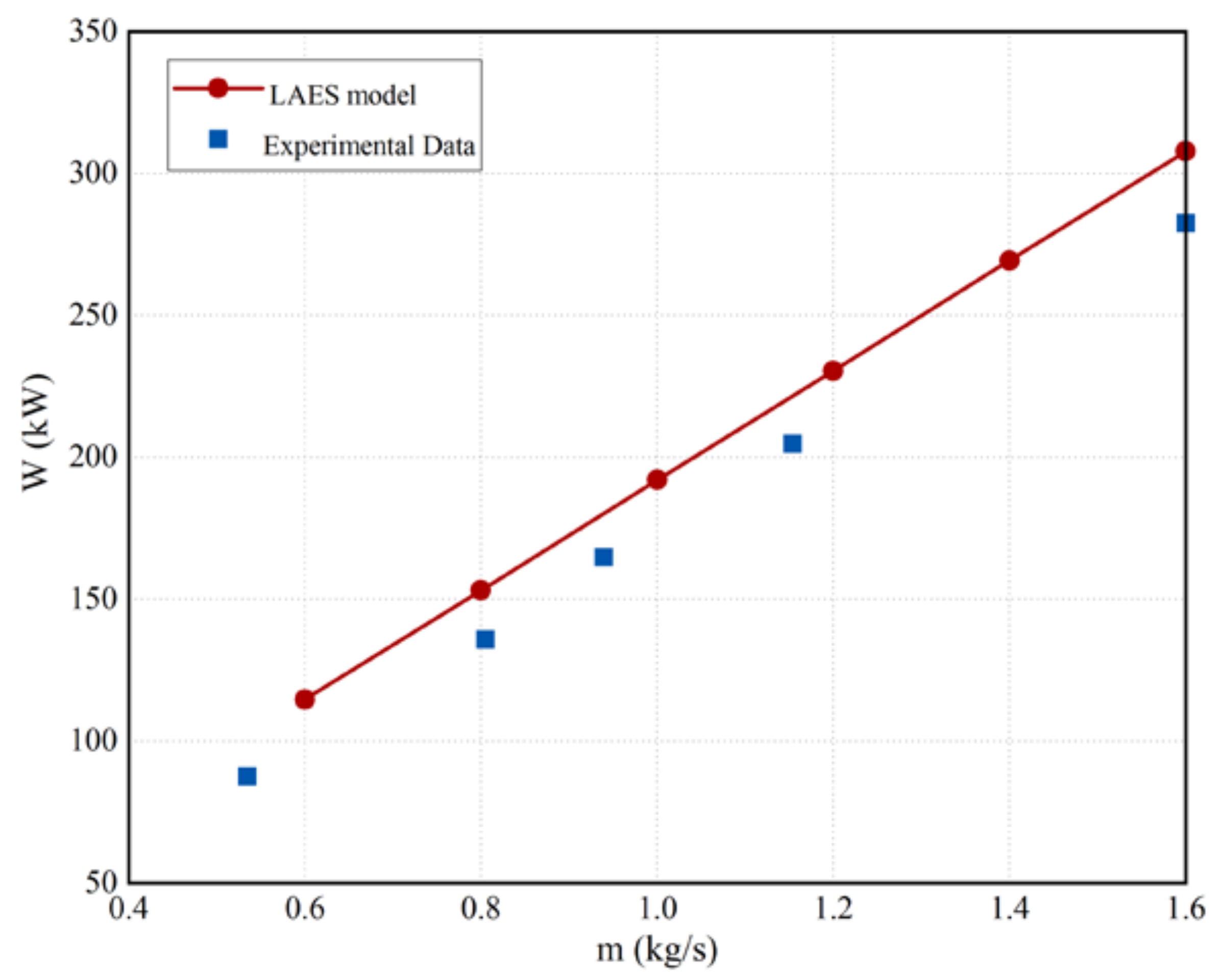
2.5.2. Model Validation of the Proposed LAES System

Figure 6 shows the model validation of the proposed LAES system. The model of discharging cycle in the proposed LAES system is verified by the experiments of LAES pilot plant from [38]. Figure 6 compares the power generation of the LAES system, the simulation results match well with the testing results. The maximum deviation of 7.4%. Thus, the mathematical model of the proposed LAES system is valid to be calculated.

3. Results and Discussion

3.1. Physical Characterization of Cold Storage Materials

The parameters of the heat transfer fluids can be obtained from REFPROP, which change with temperature and pressure. REFPROP is a software to investigate the physical properties of refrigerants, which is developed by the American Institute of Standards Technology (NIST) [39]. However, the parameters of selected cold storage materials (i.e., white cobbles) are unknown. The physical properties of the white cobbles should be characterized first. Density, specific heat capacity, and thermal conductivity were measured for subsequent modeling and calculation.

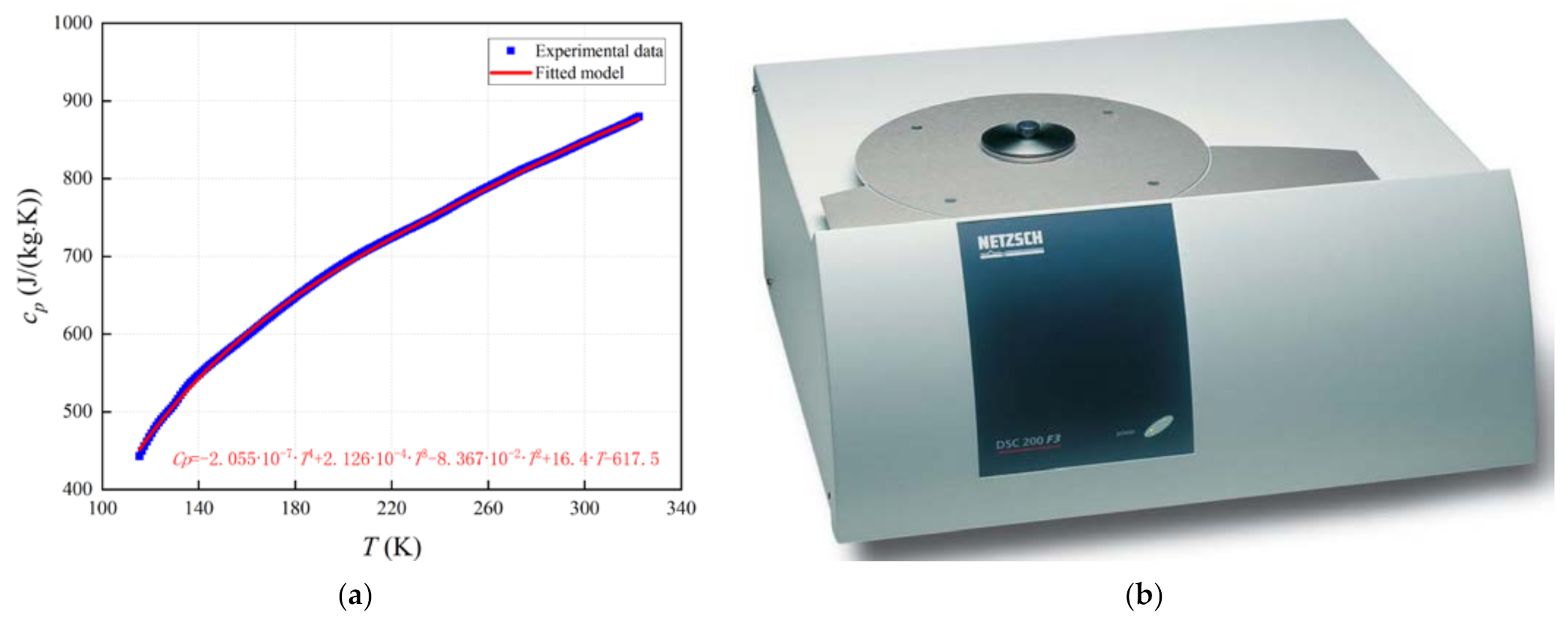
3.1.1. Density of White Cobbles

The density of the white cobbles was determined by dividing the mass in kilograms and the volume in cubic meters. The mass is measured by an AUW320 dual-range semi-micro balance (±0.0001 g, see Figure 7b). The volume is measured by the drainage method, using a graduated cylinder (250 ± 2 mL, see Figure 7b). The apparatuses for testing the density of rocks are shown in Figure 7. The average density of particles is achieved at a value of 2815 kg/m3 through multiple measurements.

3.1.2. Specific Heat Capacity of White Cobbles

Differential scanning calorimetry (DSC) is used to calculate the specific heat of the white cobbles. It is possible to calculate the unknown heat capacity of material by analyzing the difference in heat flow between a sample (sapphire) with a well-known heat capacity and the material, which is called the sapphire method. NETZSCH DSC 200F3 is used to obtain the specific heat capacity of white cobbles from ~115 K to ~330 K (see Figure 8b). Figure 8a shows its changes with temperature, which also presents the fitted equation. The maximum deviation between test and fitted results is 0.064%.

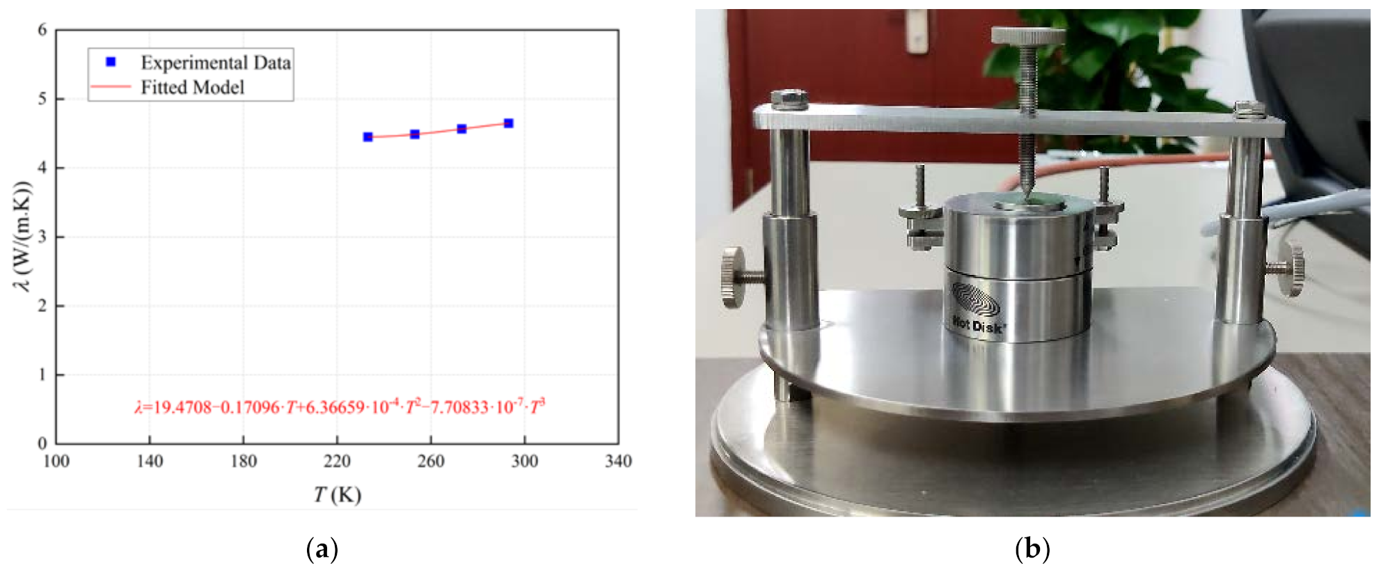
3.1.3. Thermal Conductivity of Particles

Hot Disk TPS 2500S is an apparatus that measures the thermal conductivity of materials based on Fourier’s thermal conductivity law. The thermal diffusivity (mm2/s) and specific heat (MJ/m3∙K) obtained by TPS 2500S are used to calculate the thermal conductivity of white cobbles (see Figure 9b). When preparing the materials for testing, the white cobbles should be cut into slices, otherwise the measurement is not accurate enough. Two slices of the same size are needed to hold the probe tightly. The thermal conductivity of white cobbles from 233 K to 293 K is shown in Figure 9a, which also changes with temperature. The maximum deviation between test and fitted results is 0.005%.

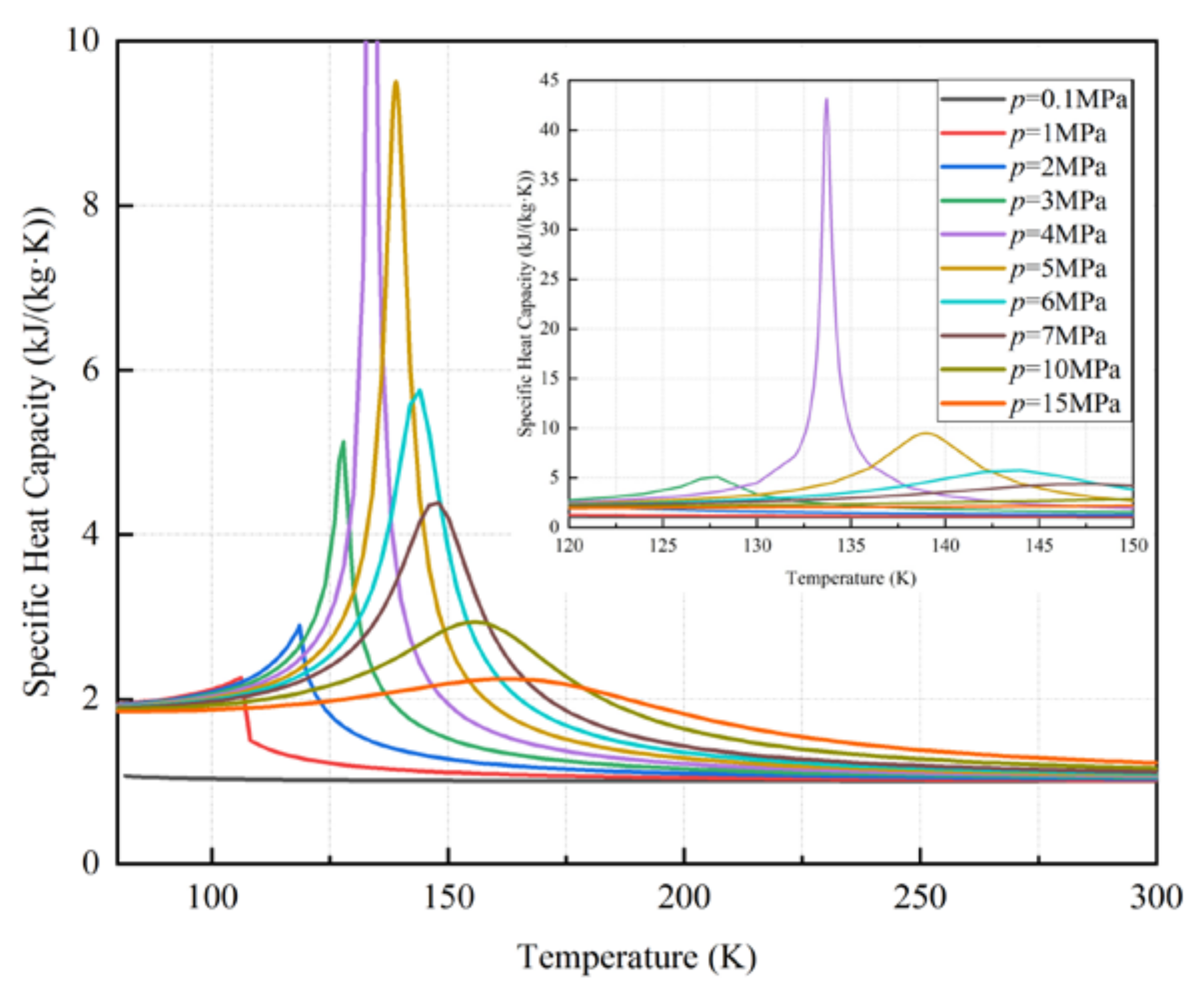
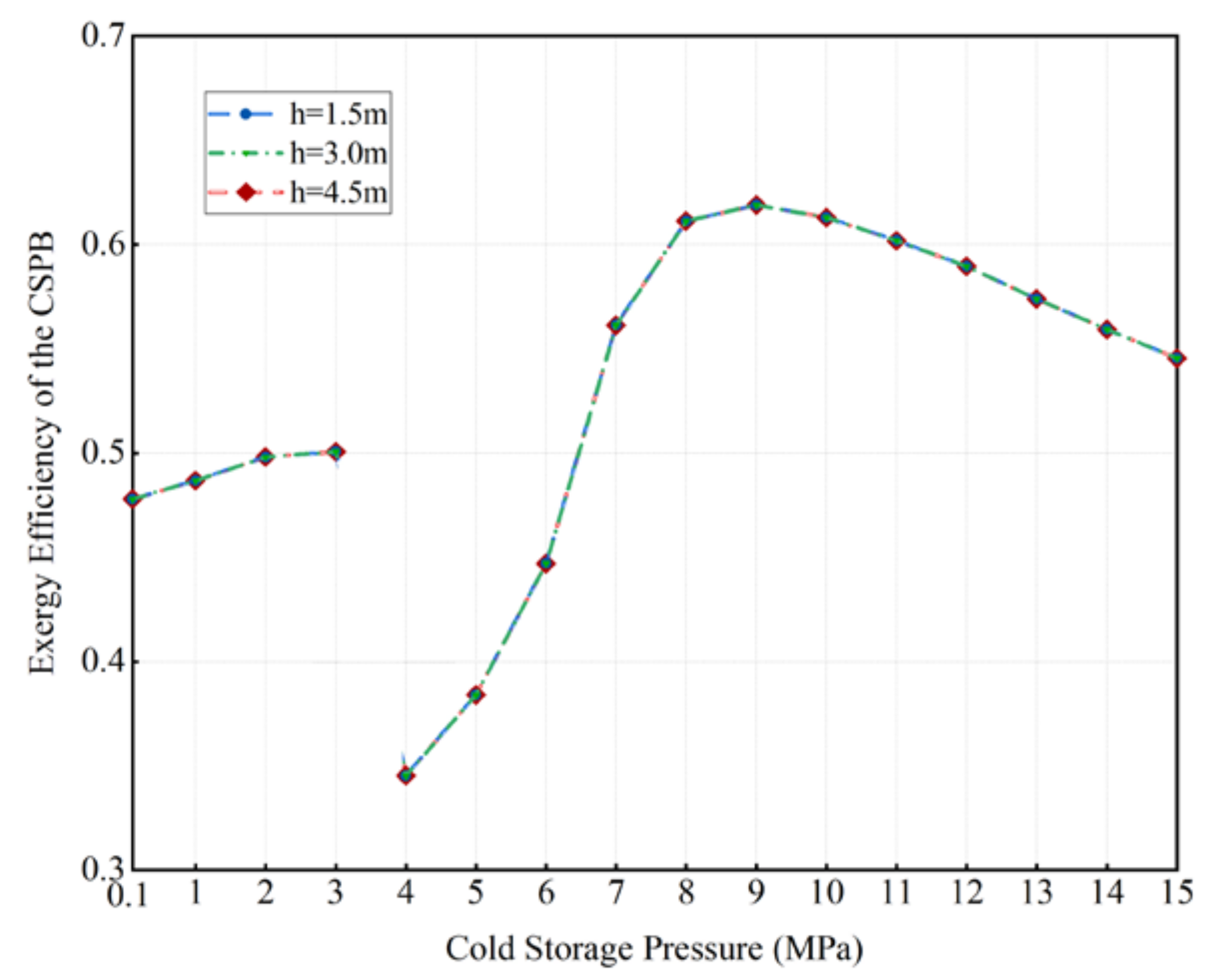
3.2. The Effects of Cold Storage Pressure on the LAES System

The air works as a carrier in a liquid form for storing electricity is an interesting material. As shown in Figure 10, the specific heat (cp) of air at different pressures varies with temperature and pressure, which comes from REFPROP. It can be seen that at low pressure (~0.1 MPa), the specific heat of air changes slightly from low temperature to high temperature. However, the specific heat capacity of air changes significantly when the pressure increases from 3 MPa to 15 MPa. When the pressure is near 4 MPa, the specific heat capacity of air reaches a peak at the temperature of 133.7 K. This is mainly because that the temperature changes slightly near 133.7 K with the same heat flow per mass.
As discussed in many studies [24,40,41], the cold box accounts for the enormous exergy destruction among the heat exchangers. A better temperature gradient match of the heat transfer fluids inside the cold box results in a higher exergy efficiency of the cold box and hence a better RTE. However, it is a challenge as the working air experienced a large temperature range from ~80 K (liquid air temperature) to ~293 K (ambient temperature). The pressure of working air during the charging and discharging process is usually over 5 MPa, which leads to obvious specific heat changes. Pressurized air is naturally considered as the cold recovery fluid due to the similar specific heat changes in the cold box.
Figure 11 shows the effects of the cold storage pressure on the LAES system, neglecting the exergy destruction of the CSPBs, in terms of the exergy efficiencies of cold box and evaporator, as well as idea liquid yield and RTE. As the cold storage pressure increases (0.1–15 MPa), the ideal RTE increases from 0.394 at 0.1 MPa to a peak value of 0.458 at 2 MPa, then decreases to a valley value of 0.425 at 4 MPa, subsequently increases until a plateau is achieved with the highest value of 0.529. The ideal liquid yield follows this regularity, which varies from 0.510 to 0.708. This regularity is mainly caused by the combination of the exergy efficiencies of the cold box and evaporator. Therefore, it can be concluded that the more similar changes in specific heat capacities of working air and pressurized air in the cold box and evaporator results in the higher RTE without considering the exergy destruction of the CSPB.
To achieve the highest RTE, an optimal cold storage pressure is observed from Figure 11, which is 8 MPa or more. However, the gas pressure is difficult to be achieved at 8 MPa for real-world application. High cold storage pressure (upper than 8 MPa) means strict requirements for the devices with small enhancement in the round trip efficiency, which is not cost-effective. Figure 11 is discussed in terms of idealized analysis. All in all, the pressurized air at 5 MPa for cold recovery is considered in the subsequent experimental-scale system simulation. The stream parameters are shown in Table 2.

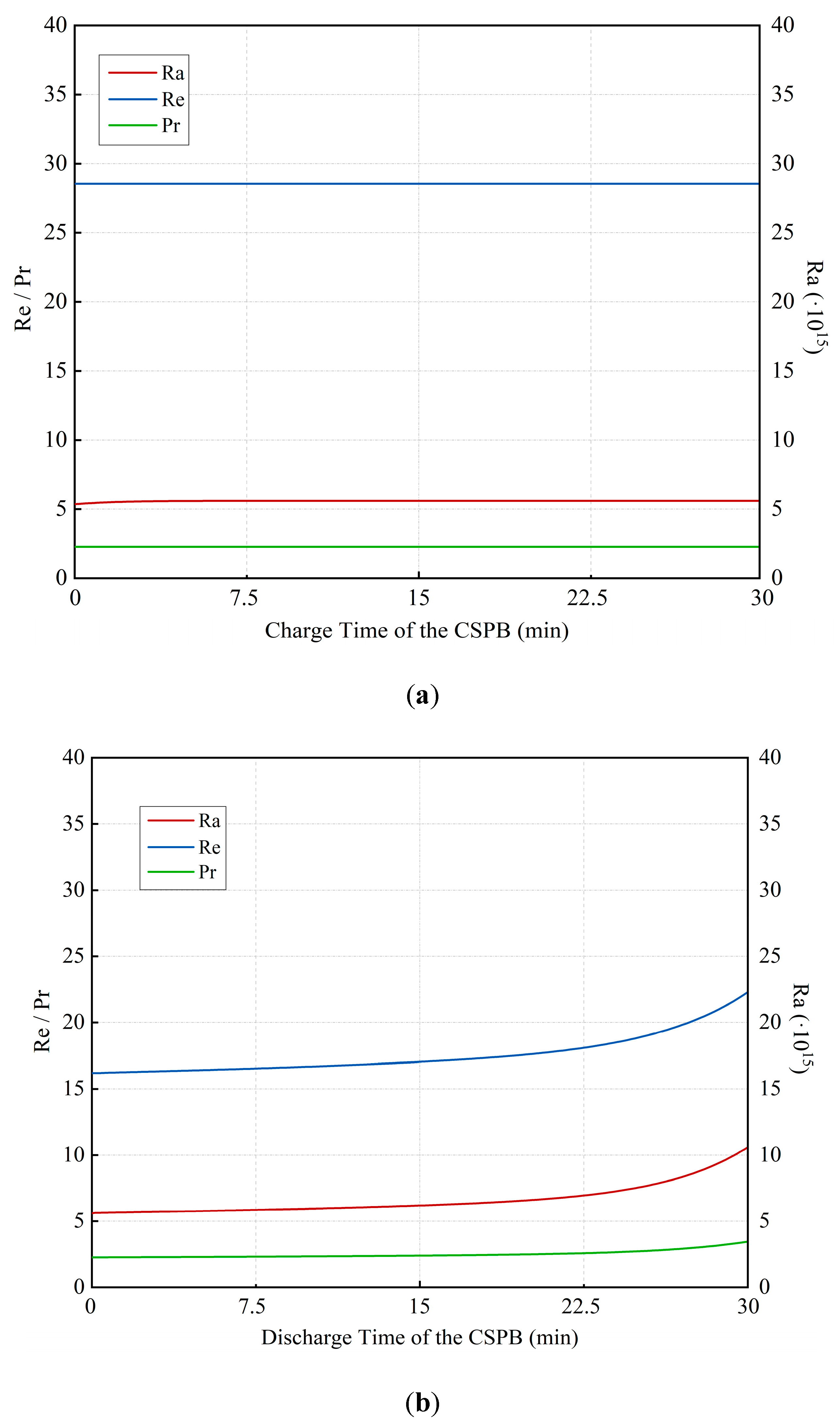
3.3. Dynamic Performance of the Cold Storage Packed Bed

The cold energy cannot be extracted from the CSPB totally, and the exergy destruction of the CSPB should not be neglected. Three cases with different sizes of the CSPBs are considered and compared (see Table 3); the charge and discharge flowrates of air are both 0.02 kg/s in an experimental scale with a charge/discharge time of 0.5 h.
The effects of the cold storage pressure on the thermodynamic performance of the CSPBs are investigated. Figure 12 shows the exergy efficiencies of the CSPBs with different sizes for the single cycle (including a charge process and a discharge process). As the cold storage pressure increases from 0.1 MPa to 3 MPa (i.e., the cold recovery fluid is non-supercritical air), the exergy efficiency of the CSPB increases from 0.478 to 0.501. As the cold storage pressure increases from 4 MPa to 15 MPa (i.e., the cold recovery fluid is supercritical air), the exergy efficiency of the CSPB increases from 0.345, reaches a peak value of 0.619 at 9 MPa, and declines since then. We can conclude that whether it is non-supercritical (0.1–3 MPa) and supercritical (4–9 MPa) air, increasing the cold storage pressure reasonably is beneficial to the exergy efficiency of the CSPB. It can be also observed that the bed size has little effect on the exergy efficiency for the single cycle. This is mainly because the cold energy has not cooled the bed adequately for the first cyclic operation. Moreover, considering the combinatorial effects of cold storage pressure on the heat exchangers for cold recovery (cold box and evaporator) and the CSPB, increasing the pressure in the allowable range results in decreased exergy destruction of the LAES system. The cold storage pressure should not be over 9 MPa, as well as those high pressures are hardly implemented for the up-to-date cold storage technologies.
The CSPB is reported to undergo dynamic processes, of which the rock temperature varies with space and time. The cold energy is gradually accumulated in the bed until it achieves a stable state. Figure 13 shows the rock temperature distributions in the CSPB from the first cycle to the stable state. In the first cycle (see Figure 13a), the particles are in thermal balance with ambiance at first. With the cold pressurized air (5 MPa) flowing from the bottom (z = 0 m) to the top (z = 1.5 m) in the charge time (0–30 min), the cold energy from the charge air is transferred to the rocks inside the bed. The particles at the lower height are easier to be cooled to a low temperature. With the pressurized air (5 MPa) flowing from the top to the bottom in the discharge time (30–60 min), the cold energy stored in the rocks is extracted, whereas the rock temperature increases. Figure 13b,c show the rock temperature distributions in the second and fourth cycle respectively, the thermoclines gradually widen and move toward the cold end. Through cyclic operations, the thermoclines appear from low temperature (~130 K) to high temperature (293 K). When the packed bed reaches a stable state in the ninth cycle (see Figure 13d), the rock temperature distributions at the beginning are nearly the same as the end. Furthermore, note that non-dimensional numbers are widely used in the area of fluid mechanics because they can characterize complex phenomena by simple number comparison. These dimensionless forms provide help in simulating mathematical models. Figure 14 shows the time evolution of Reynolds, Prandtl and Rayleigh numbers at the cold end (bottom) of the CSPB (z = 0 m). According to the Reynolds number, the inlet air is generally laminar.

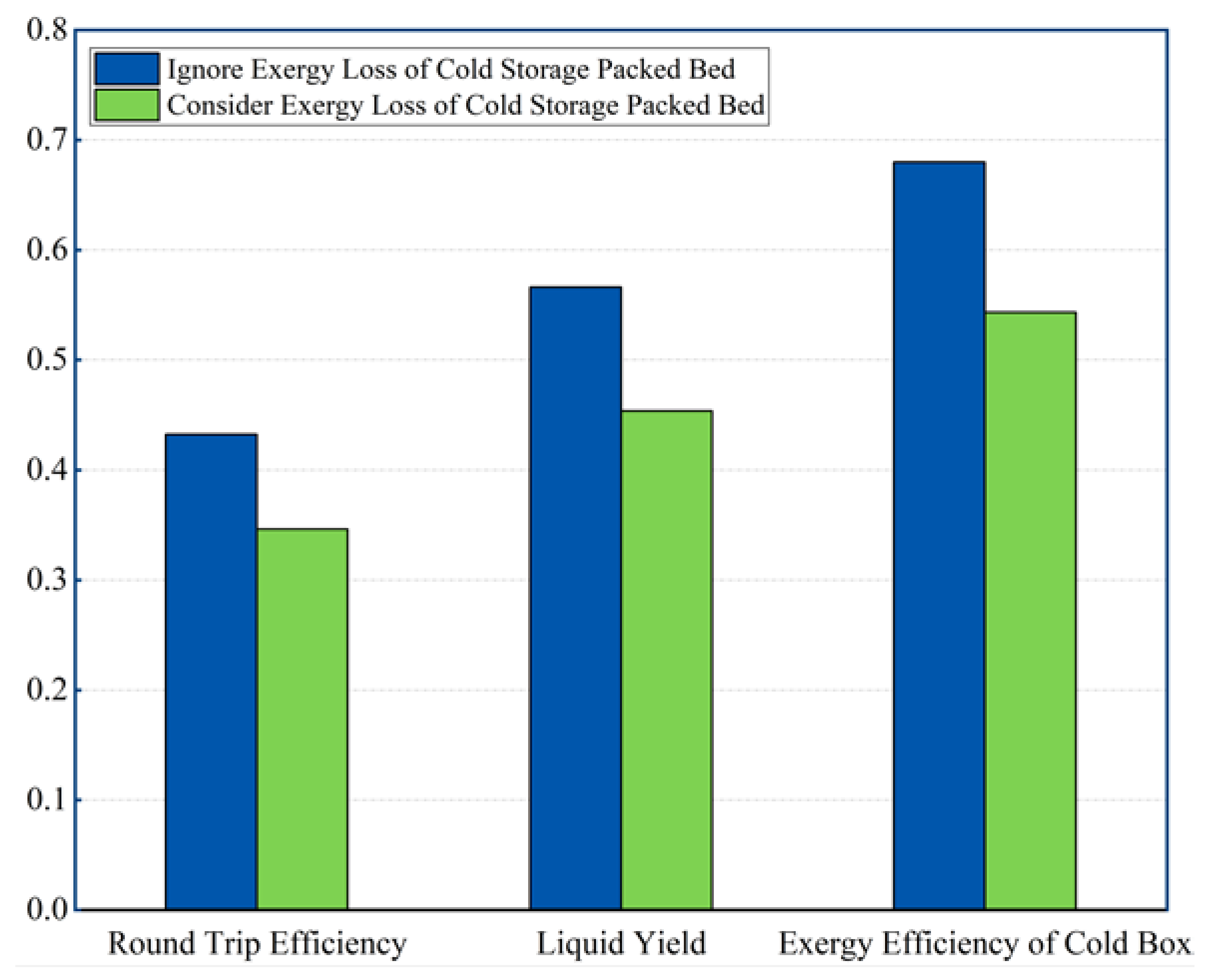
3.4. System Performance Considering the Exergy Loss in the Cold Storage Packed Bed

Figure 15 compares the thermodynamic performance of the LAES system with and without exergy loss in the CSPB. Under the cold storage pressure of 5 MPa, the experimental-scale LAES system has an ideal liquid yield of 56.62% and an ideal RTE of 43.24%, without considering the exergy loss of CSPB. However, the cold energy for enhancing air liquefaction is contracted due to the exergy destruction in the CSPB, which results in less liquid air production and hence a lower realistic liquid yield of 45.37% and a lower realistic RTE of 34.63%. The RTE revealed in this study is unfavorable when compared to the accepted value of ~50% for LAES. The CSPB has a significant effect on the thermodynamic performance of the system level of LAES, especially for the experiment scale.

4. Conclusions

The LAES is becoming popular for decarbonizing networks, which includes charging (air liquefaction), storage, and discharging (power generation) processes. The packed bed filled with rocks/pebbles for cold storage is more promising for real-world application compared to the liquids for cold storage. The heat transfer fluid in the cold storage packed bed (CSPB) is generally ambient-pressure air or pressurized air. However, there is little research concerning thermodynamic performance under different cold storage pressure and the effect of the CSPB on the LAES system. This paper presents a standalone LAES system based on our previous work. The idealistic system simulation is first conducted with the sensitive analysis of cold storage pressure, ignoring the exergy loss of packed bed cold storage. With the physical properties of the selected cold storage materials characterized, the dynamic model of the CSPB is established and simulated. Finally, the real-world RTE of an experimental-scale LAES system is evaluated considering the exergy loss of the CSPB. The key conclusions are summarized as follows:
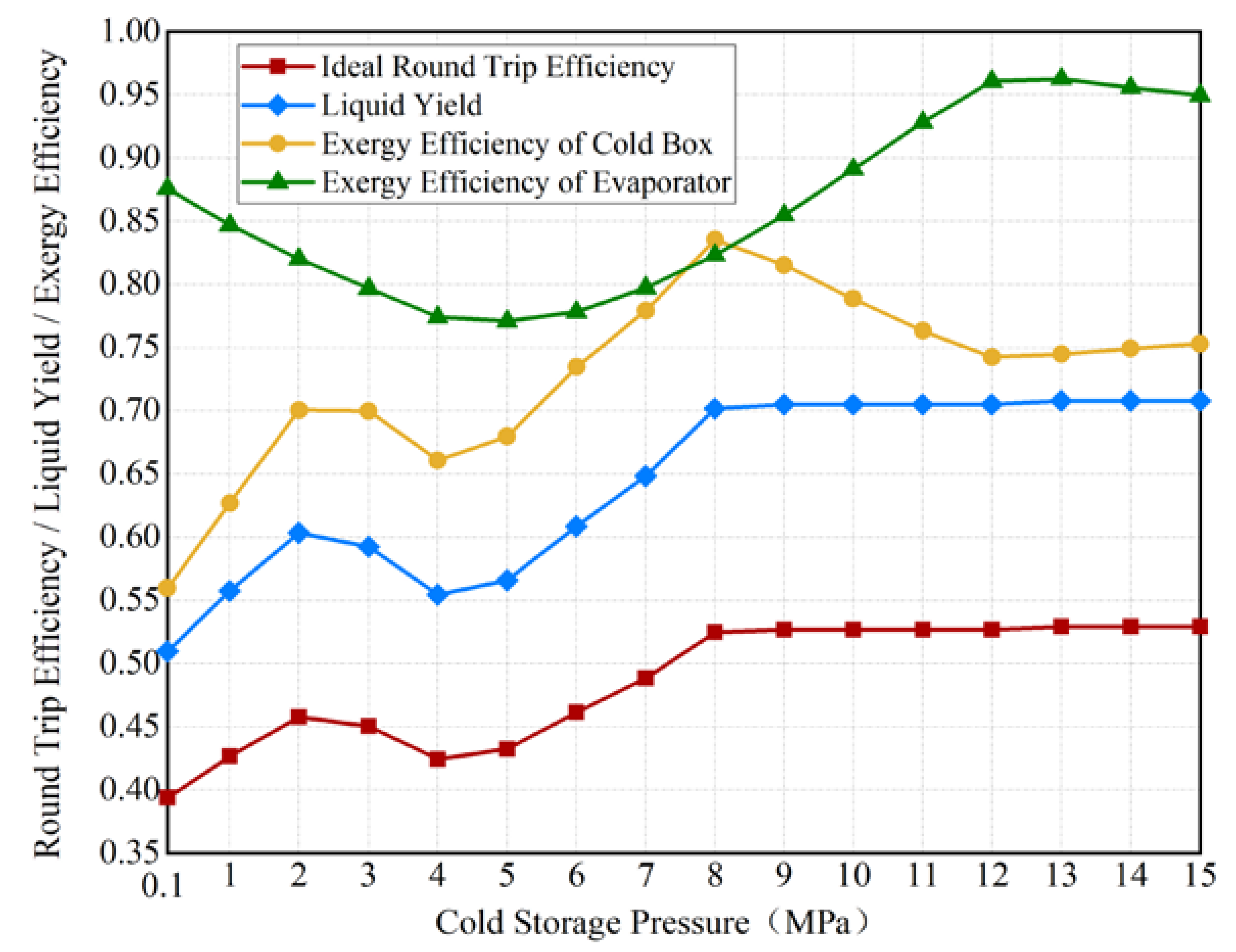
  • The cold storage pressure has a significant influence on the thermodynamic performance of the LAES system. The proposed LAES system has an ideal RTE of 39.38–52.91%, without the exergy loss of the CSPB.
  • Employed packed bed for cold storage leads to contracted cold contribution to the air liquefaction from liquid air evaporation. The RTE declines by 19.91% considering the exergy loss of the CSPB, compared to the ideal RTE.
  • Increasing the cold storage pressure reasonably is beneficial to the exergy efficiency of the CSPB, whether it is non-supercritical air under the pressure of 0.1 MPa–3 MPa or supercritical air under the pressure of 4 MPa–9 MPa.
  • The characterizations of the cold storage material are conducted, which indicates that as temperature increases, its specific heat capacity and thermal conductivity both increase.

Author Contributions

Conceptualization, C.W.; methodology, C.W.; software, Y.B. and C.W.; validation, Y.B.; formal analysis, Y.B. and C.W.; investigation, Y.B. and C.W.; resources, X.Z. and S.S.; data curation, Y.B.; writing—original draft preparation, Y.B.; writing—review and editing, Y.B. and C.W.; visualization, L.X.; supervision, X.Z. and W.Q.; project administration, X.Z. and R.Q.; funding acquisition, Y.W. All authors have read and agreed to the published version of the manuscript..

Funding

This research was funded by [Basic Research on Droplet Generation Mechanism and Propagation Characteristics in Air Treatment] grant number [No. 6503007533] and the APC was funded by [Basic Research on Droplet Generation Mechanism and Propagation Characteristics in Air Treatment] grant number [No. 6503007533].

Institutional Review Board Statement

Not applicable.

Informed Consent Statement

Not applicable.

Data Availability Statement

Not applicable.

Acknowledgments

The research described in this paper is supported by Basic Research on Droplet Generation Mechanism and Propagation Characteristics in Air Treatment (No. 6503007533) and the Key Industrial Innovation Program of Suzhou (No. SGC2020031).

Conflicts of Interest

The authors declare no conflict of interest.

Nomenclature

Δmmass difference (K)
Δttime step (s)
Δzspace step (m)
cpSpecific heat (J/(kg·K))
Ddiameter of packed bed, i.e., internal diameter of the tank (m)
dpdiameter of particles (m)
especific exergy (J/kg)
GrGrashof number
hheat transfer coefficient (W/(m2·K))
heenthalpy (J/kg)
mmass flowrate (kg/s)
NuNusselt number
Ppressure (MPa)
PrPrandtl number
Qheat flux (W)
RaRayleigh number
ReReynolds number
sspecific entropy (J/(kg·K))
Ttemperature (K)
ttime (s)
uvelocity (m/s)
Wpower (kW)
Yliquid yield
zheight of packed bed (m)
Greek symbols
εporosity
ηefficiency
λthermal conductivity (W/(m·K))
μviscosity (Pa·s)
ρdensity (kg/m3)
Subscripts
0ambience
aveaverage
chargingcharging cycle of the LAES system
dischargingdischarging cycle of the LAES system
ffluid
iindex for cell number
ininlet
isoisentropic
outoutlet
Pumpcryo-pump
ssolid
surfacethe surface of the bed
tratransient
wwall
Acronyms
ACair compressor
ATair turbine
CSPBcold storage packed bed
CTcryo-turbine
EEexergy efficiency
HSPBheat storage packed bed
LAliquid air
LAESliquid air energy storage
PApressurized air
PCpower consumption
POpower output
RTEround trip efficiency

References

  1. IEA Renewable Energy Market Update. 2021. Available online: https://www.iea.org/reports/renewable-energy-market-update-2021 (accessed on 31 July 2021).
  2. RENEWABLES 2020 GLOBAL STATUS REPORT. Available online: https://www.ren21.net/wp-content/uploads/2019/05/gsr_2020_full_report_en.pdf (accessed on 4 July 2021).
  3. Denholm, P.; Hand, M. Grid flexibility and storage required to achieve very high penetration of variable renewable electricity. Energy Policy 2011, 39, 1817–1830. [Google Scholar] [CrossRef]
  4. Rodrigues, E.M.G.; Godina, R.; Santos, S.F.; Bizuayehu, A.W.; Contreras, J.; Catalão, J.P.S. Energy storage systems supporting increased penetration of renewables in islanded systems. Energy 2014, 75, 265–280. [Google Scholar] [CrossRef]
  5. Zhang, M.; Wang, C.; Luo, A.; Liu, Z.; Zhang, X. Molecular dynamics simulation on thermophysics of paraffin/EVA/graphene nanocomposites as phase change materials. Appl. Therm. Eng. 2020, 166, 114639. [Google Scholar] [CrossRef]
  6. Sun, X.; Mahdi, J.M.; Mohammed, H.I.; Majdi, H.S.; Zixiong, W.; Talebizadehsardari, P. Solidification Enhancement in a Triple-Tube Latent Heat Energy Storage System Using Twisted Fins. Energies 2021, 14, 7179. [Google Scholar] [CrossRef]
  7. Gao, Y.; Hu, G.; Zhang, Y.; Zhang, X. An experimental study of a hybrid photovoltaic thermal system based on ethanol phase change self-circulation technology: Energy and exergy analysis. Energy 2022, 238, 121663. [Google Scholar] [CrossRef]
  8. Ghalambaz, M.; Zhang, J. Conjugate solid-liquid phase change heat transfer in heatsink filled with phase change material-metal foam. Int. J. Heat Mass Transf. 2020, 146, 118832. [Google Scholar] [CrossRef]
  9. Hu, Y.; Huang, D.; Qi, Z.; He, S.; Yang, H.; Zhang, H. Modeling thermal insulation of firefighting protective clothing embedded with phase change material. Heat Mass Transf. 2012, 49, 567–573. [Google Scholar] [CrossRef]
  10. Li, Y.; Chen, H.; Zhang, X.; Tan, C.; Ding, Y. Renewable energy carriers: Hydrogen or liquid air/nitrogen? Appl. Therm. Eng. 2010, 30, 1985–1990. [Google Scholar] [CrossRef] [Green Version]
  11. Emiliano, B.; Alessio, T.; Alessandro, R.; Gabriele, C. A review on liquid air energy storage: History, state of the art and recent developments. Renew. Sustain. Energy Rev. 2021, 137, 110572. [Google Scholar]
  12. Smith, E.M. Storage of electrical energy using supercritical liquid air. Proc. Inst. Mech. Eng. 1977, 191, 289–298. [Google Scholar] [CrossRef]
  13. Kooichi Chino, H.A. Evaluation of energy storage method using liquid air. Heat Transf. 2000, 29, 347–357. [Google Scholar]
  14. Morgan, R.; Nelmes, S.; Gibson, E.; Brett, G. Liquid air energy storage—Analysis and first results from a pilot scale demonstration plant. Appl. Energy 2015, 137, 845–853. [Google Scholar] [CrossRef]
  15. Sciacovelli, A.; Vecchi, A.; Ding, Y. Liquid air energy storage (LAES) with packed bed cold thermal storage—From component to system level performance through dynamic modelling. Appl. Energy 2017, 190, 84–98. [Google Scholar] [CrossRef] [Green Version]
  16. Legrand, M.; Rodríguez-Antón, L.M.; Martinez-Arevalo, C.; Gutiérrez-Martín, F. Integration of liquid air energy storage into the spanish power grid. Energy 2019, 187, 115965. [Google Scholar] [CrossRef]
  17. Vecchi, A.; Li, Y.; Mancarella, P.; Sciacovelli, A. Integrated techno-economic assessment of Liquid Air Energy Storage (LAES) under off-design conditions: Links between provision of market services and thermodynamic performance. Appl. Energy 2020, 262, 114589. [Google Scholar] [CrossRef]
  18. Wang, C.; Bian, Y.; You, Z.; Luo, Y.; Zhang, X.; Peng, H.; Ding, Y.; She, X. Dynamic analysis of a novel standalone liquid air energy storage system for industrial applications. Energy Convers. Manag. 2021, 245, 114537. [Google Scholar] [CrossRef]
  19. Li, Y.; Cao, H.; Wang, S.; Jin, Y.; Li, D.; Wang, X.; Ding, Y. Load shifting of nuclear power plants using cryogenic energy storage technology. Appl. Energy 2014, 113, 1710–1716. [Google Scholar] [CrossRef]
  20. She, X.; Peng, X.; Nie, B.; Leng, G.; Zhang, X.; Weng, L.; Tong, L.; Zheng, L.; Wang, L.; Ding, Y. Enhancement of round trip efficiency of liquid air energy storage through effective utilization of heat of compression. Appl. Energy 2017, 206, 1632–1642. [Google Scholar] [CrossRef]
  21. Peng, X.; She, X.; Cong, L.; Zhang, T.; Li, C.; Li, Y.; Wang, L.; Tong, L.; Ding, Y. Thermodynamic study on the effect of cold and heat recovery on performance of liquid air energy storage. Appl. Energy 2018, 221, 86–99. [Google Scholar] [CrossRef]
  22. Zhang, T.; Zhang, X.; Xue, X.; Wang, G.; Mei, S. Thermodynamic Analysis of a Hybrid Power System Combining Kalina Cycle with Liquid Air Energy Storage. Entropy 2019, 21, 220. [Google Scholar] [CrossRef] [PubMed] [Green Version]
  23. She, X.; Zhang, T.; Peng, X.; Wang, L.; Tong, L.; Luo, Y.; Zhang, X.; Ding, Y. Liquid Air Energy Storage for Decentralized Micro Energy Networks with Combined Cooling, Heating, Hot Water and Power Supply. J. Therm. Sci. 2020, 30, 1–17. [Google Scholar] [CrossRef]
  24. Qi, M.; Park, J.; Kim, J.; Lee, I.; Moon, I. Advanced integration of LNG regasification power plant with liquid air energy storage: Enhancements in flexibility, safety, and power generation. Appl. Energy 2020, 269, 115049.1–115049.18. [Google Scholar] [CrossRef]
  25. Zhang, T.; Chen, L.; Zhang, X.; Mei, S.; Xue, X.; Zhou, Y. Thermodynamic analysis of a novel hybrid liquid air energy storage system based on the utilization of LNG cold energy. Energy 2018, 155, 641–650. [Google Scholar] [CrossRef]
  26. Al-Zareer, M.; Dincer, I.; Rosen, M.A. Analysis and assessment of novel liquid air energy storage system with district heating and cooling capabilities. Energy 2017, 141, 792–802. [Google Scholar] [CrossRef]
  27. Wang, C.; Zhang, X.; You, Z.; Zhang, M.; Huang, S.; She, X. The effect of air purification on liquid air energy storage—An analysis from molecular to systematic modelling. Appl. Energy 2021, 300, 117349. [Google Scholar] [CrossRef]
  28. Wen, D.; Ding, Y. Heat transfer of gas flow through a packed bed. Chem. Eng. Sci. 2006, 61, 3532–3542. [Google Scholar] [CrossRef]
  29. Liu, J.; Wang, L.; Yang, L.; Yue, L.; Chai, L.; Sheng, Y.; Chen, H.; Tan, C. Experimental study on heat storage and transfer characteristics of supercritical air in a rock bed. Int. J. Heat Mass Transf. 2014, 77, 883–890. [Google Scholar] [CrossRef]
  30. Chai, L.; Liu, J.; Wang, L.; Yue, L.; Yang, L.; Sheng, Y.; Chen, H.; Tan, C. Cryogenic energy storage characteristics of a packed bed at different pressures. Appl. Therm. Eng. Des. Process. Equip. Econ. 2014, 63, 439–446. [Google Scholar] [CrossRef]
  31. Ismail, K.A.R.; Stuginsky, R., Jr. A parametric study on possible fixed bed models for pcm and sensible heat storage. Appl. Therm. Eng. 1999, 19, 757–788. [Google Scholar] [CrossRef]
  32. Esence, T.; Bruch, A.; Fourmigué, J.-F.; Stutz, B. A versatile one-dimensional numerical model for packed-bed heat storage systems. Renew. Energy 2019, 133, 190–204. [Google Scholar] [CrossRef]
  33. Wakao, N.; Tanisho, S. Chromatographic measurements of particle—Gas mass transfer coefficients at low Reynolds numbers in packed beds. Pergamon 1974, 29, 1991–1994. [Google Scholar] [CrossRef]
  34. Incropera, F.P.; Dewitt, D.P.; Bergman, T.L.; Lavine, A.S. Introduction to Conduction. In Fundamentals of Heat and Mass Transfer; Wiley: Hoboken, NJ, USA, 2007; pp. 57–82. [Google Scholar]
  35. Incropera, F.P.; Dewitt, D.P.; Bergman, T.L.; Lavine, A.S. Introduction to Convection. In Fundamentals of Heat and Mass Transfer; Wiley: Hoboken, NJ, USA, 2007; pp. 347–387. [Google Scholar]
  36. Fachlicher Träger VDI-Gesellschaft Verfahrenstechnik und Chemieingenieurwesen. In VDI-Wärmeatlas; Springer: Berlin/Heidelberg, Germany, 2006.
  37. Lukasz, S.; Piotr, K.; Marcin, W. Exergy Analysis of Adiabatic Liquid Air Energy Storage (A-LAES) System Based on Linde–Hampson Cycle. Energies 2021, 14, 945. [Google Scholar]
  38. Peng, X.; She, X.; Li, C.; Luo, Y.; Zhang, T.; Li, Y.; Ding, Y. Liquid air energy storage flexibly coupled with LNG regasification for improving air liquefaction. Appl. Energy 2019, 250, 1190–1201. [Google Scholar] [CrossRef]
  39. Lemmon, E.W.; Huber, M.L.; McLinden, M.O. Reference fluid thermodynamic and transport properties (REFPROP). In NIST Standard Reference Database 23 Version 9.1; National Institute of Standards and Technology (NIST): Gaithersburg, MD, USA, 2013. [Google Scholar]
  40. Ebrahimi, A.; Ghorbani, B.; Skandarzadeh, F.; Ziabasharhagh, M. Introducing a novel liquid air cryogenic energy storage system using phase change material, solar parabolic trough collectors, and Kalina power cycle (process integration, pinch, and exergy analyses). Energy Convers. Manag. 2021, 228, 113653. [Google Scholar] [CrossRef]
  41. Nabat, M.H.; Zeynalian, M.; Razmi, A.R.; Arabkoohsar, A.; Soltani, M. Energy, exergy, and economic analyses of an innovative energy storage system; liquid air energy storage (LAES) combined with high-temperature thermal energy storage (HTES). Energy Convers. Manag. 2020, 226, 113486. [Google Scholar] [CrossRef]
Figure 1. The simplified block diagram of the LAES system. Adapted from Ref. [11].
Energies 15 00036 g001
Figure 2. The specific flow figure of the proposed LAES system.
Energies 15 00036 g002
Figure 3. Chart of the charge and discharge process of packed bed energy storage (a) and the picture of cold storage packed bed (b).
Energies 15 00036 g003
Figure 4. Schematic of solution methodology of this work.
Energies 15 00036 g004
Figure 5. Model validation of the cold storage packed bed.
Energies 15 00036 g005
Figure 6. Model validation of the proposed LAES system.
Energies 15 00036 g006
Figure 7. The apparatuses for testing density of rocks: (a) AUW320 dual-range semi-micro balance; (b) graduated cylinder.
Energies 15 00036 g007
Figure 8. Specific heat capacity of the white cobbles by experiments (a) and the testing apparatus—NE-TZSCH DSC 200F3 (b).
Energies 15 00036 g008
Figure 9. Thermal conductivity of the particles by experiments (a) and the testing apparatusHot Disk TPS 2500S (b).
Energies 15 00036 g009
Figure 10. Temperature dependence of the specific heat capacity of air under different pressures.
Energies 15 00036 g010
Figure 11. The effects of the cold storage pressure on the efficiencies of the LAES system.
Energies 15 00036 g011
Figure 12. The effects of the cold storage pressure on the exergy efficiencies of the CSPB for different cases at the first cycle.
Energies 15 00036 g012
Figure 13. Temperature distributions of rock particles in the CSPB with cycles: (a) cycle 1, (b) cycle 2, (c) cycle 4, (d) cycle 9.
Energies 15 00036 g013
Figure 14. Operation time dependence of non-dimensional numbers at the bottom of cold storage packed bed (z = 0 m) at the ninth cycle: (a) charge time, (b) discharge time.
Energies 15 00036 g014
Figure 15. Thermodynamic performance with/without exergy loss of the CSPB.
Energies 15 00036 g015
Table 1. Operation conditions of the CSPB in model validation.
Inner Diameter of Cold Storage Packed Bed12 m
Height of the Cold Storage Packed Bed13.65 m
Inlet Air Mass Flow Rate406.6 kg/s
Pressure of Inlet Air0.15 MPa
Temperature of Inlet Air278.2 K
Table 2. Simulation parameters of the LAES system with pressurized air (5 MPa).
Statem (kg/s)T (K)P (kPa)Medium
10.028293.000100.000Working air
20.028481.637493.240Working air
30.028299.000493.240Working air
40.028491.9252432.880Working air
50.028299.0002432.880Working air
60.028494.29212,000.000Working air
70.028299.00012,000.000Working air
80.028137.38412,000.000Working air
90.02879.583100.000Working air
100.01281.644100.000Working air
110.012246.317100.000Working air
120.01678.816100.000Working air
130.01684.64412,000.000Working air
140.016273.00012,000.000Working air
150.016441.10012,000.000Working air
160.016293.0812432.880Working air
170.016441.1002432.880Working air
180.016295.522493.240Working air
190.016441.100493.240Working air
200.016296.182100.000Working air
210.067293.000100.000Thermal oil
220.022436.810100.000Thermal oil
230.022446.100100.000Thermal oil
240.022457.605100.000Thermal oil
250.067446.900100.000Thermal oil
260.039446.100100.000Thermal oil
270.013310.295100.000Thermal oil
280.013340.634100.000Thermal oil
290.013344.813100.000Thermal oil
300.039332.200100.000Thermal oil
310.020132.5115000.000Pressurized air
320.020293.0005000.000Pressurized air
330.020293.0005000.000Pressurized air
340.020131.0005000.000Pressurized air
Table 3. Three cases for the dynamic simulation of the CSPBs.
TypeCase 1Case 2Case 3
SizeDiameter = 0.5 m
Height = 1.5 m
Diameter = 3.0 m
Height = 1.5 m
Diameter = 4.5 m
Height = 1.5 m
Charge gasPressurized air (0.1–10 MPa)
Discharge gasPressurized air (0.1–10 MPa)
Charge time0.5 h
Discharge time0.5 h
Charge flowrate0.028 kg/s
Discharge flowrate0.016 kg/s
Publisher’s Note: MDPI stays neutral with regard to jurisdictional claims in published maps and institutional affiliations.

