Article

Evaluation of the Performance Degradation of a Metal Hydride Tank in a Real Fuel Cell Electric Vehicle

by
Santiago Hernán Suárez
1,2,*,
Djafar Chabane
1,2,
Abdoul N’Diaye
1,2,
Youcef Ait-Amirat
2,
Omar Elkedim
1,2 and
Abdesslem Djerdir
1,2
1
FEMTO-ST Institute, Université Bourgogne Franche-Comté, UTBM, CNRS, 90000 Belfort, France
2
FEMTO-ST Institute, FCLAB, Université Bourgogne Franche-Comté, CNRS, 90000 Belfort, France
*
Author to whom correspondence should be addressed.
Energies 2022, 15(10), 3484; https://doi.org/10.3390/en15103484
Submission received: 11 April 2022 / Revised: 4 May 2022 / Accepted: 5 May 2022 / Published: 10 May 2022

Abstract

:
In a fuel cell electric vehicle (FCEV) powered by a metal hydride tank, the performance of the tank is an indicator of the overall health status, which is used to predict its behaviour and make appropriate energy management decisions. The aim of this paper is to investigate how to evaluate the effects of charge/discharge cycles on the performance of a commercial automotive metal hydride hydrogen storage system applied to a real FCEV. For this purpose, a mathematical model is proposed based on uncertain physical parameters that are identified using the stochastic particle swarm optimisation (PSO) algorithm combined with experimental measurements. The variation of these parameters allows an assessment of the degradation level of the tank’s performance on both the quantitative and qualitative aspects. Simulated results derived from the proposed model and experimental measurements were in good agreement, with a maximum relative error of less than 2 % . The validated model was used to establish the correlations between the observed degradations in a hydride tank recovered from a real FCEV. The results obtained show that it is possible to predict tank degradations by developing laws of variation of these parameters as a function of the real conditions of the use of the FCEV (number of charging/discharging cycles, pressures, mass flow rates, temperatures).

1. Introduction

Considering the uncertainty of fossil fuel supply, as well as its depletion and the existing environmental conditions, it is essential to replace traditional and conventional energy sources with clean, alternative, and renewable energy sources [1,2]. A number of qualities of hydrogen make it an excellent energy vector to deal with the pollution problems and energy problems that lie ahead [3].
For the hydrogen energy society to be a success, it is imperative to examine and analyse one of the most controversial issues, the storage of hydrogen for fuel cell electrical vehicles (FCEVs), which must be safe, efficient, and low-cost [4,5]. Hydrogen used in FCEVs is currently stored at high pressure, reaching up to 700 bar in the case of passenger cars such as the Toyota Mirai. This storage technology raises safety concerns, as well as the cost of developing hydrogen refuelling infrastructures. To overcome these problems, specialists present hydrogen storage in metal hydrides as a promising solution. Indeed, due to its low pressures and temperatures, this technology provides a higher level of safety than high-pressure storage [6,7]. LaNi5 is one of the most promising alloys for such storage systems due to its promising properties, such as reversibility, modest temperatures, moderate hysteresis, and decent adsorption and desorption kinetics [8].
The storage of hydrogen in the alloy takes place during a chemical reaction to form the metal hydride, a process known as absorption. When the hydride is decomposed and returns to its metal alloy form, releasing the hydrogen in gaseous form, it is called a desorption process [9]. After a large number of repetitions, undesirable alterations in the general performance of the materials may occur and may even prevent their use [10]. The reasons why hydrogen storage materials can potentially lose their capacity over cycles are classified into extrinsic and intrinsic [11]. Extrinsic reasons can be mitigated by the appropriate adjustment of external conditions, while intrinsic reasons are difficult to eliminate and remain a major research challenge [12]. The scientific literature includes as intrinsic reasons for the loss of capacity the disproportionation [13], the amorphisation [14], the generation of stable phases [10,15], and so on. However, there are little information and data to support these possible mechanisms [16]. For this reason, many research efforts are being made with the intention of improving the performance of hydride metals under the effect of the passage of the cycles [5,9,17,18].
Zhu et al. presented in [19] a dynamic model of hydride tanks for a fleet of FCEVs called Mobypost vehicles [20,21]. The physical parameters of this tank were identified from data measured during actual vehicle operation. The disadvantage of this is that the measured data include both the tanks and their associated heat exchanger, which obstructs the accurate assessment of the intrinsic performance of the tanks, namely the hydrogen concentration and the kinetics of charging and discharging. The solution provided by the work presented here is to carry out the identification of the physical parameters using laboratory experiments in which the only controlled value is the flow rate of hydrogen absorbed or desorbed by the tank.
This paper is organised into five sections. After the introductory section, which gives the general context and the objective of the present work, Section 2 is dedicated to the modelling process through the exposition of its three main aspects, which are: the dynamic modelling of the tank, the experimental characterisation of the tank, and the identification of the physical parameters of the model. Section 3 shows the application of the developed model on a tank in a healthy and degraded state. Section 4 is a study on the correlation between the degradation of the tank and the physical parameters of the developed model. Finally, Section 5 presents the main conclusions of this work.

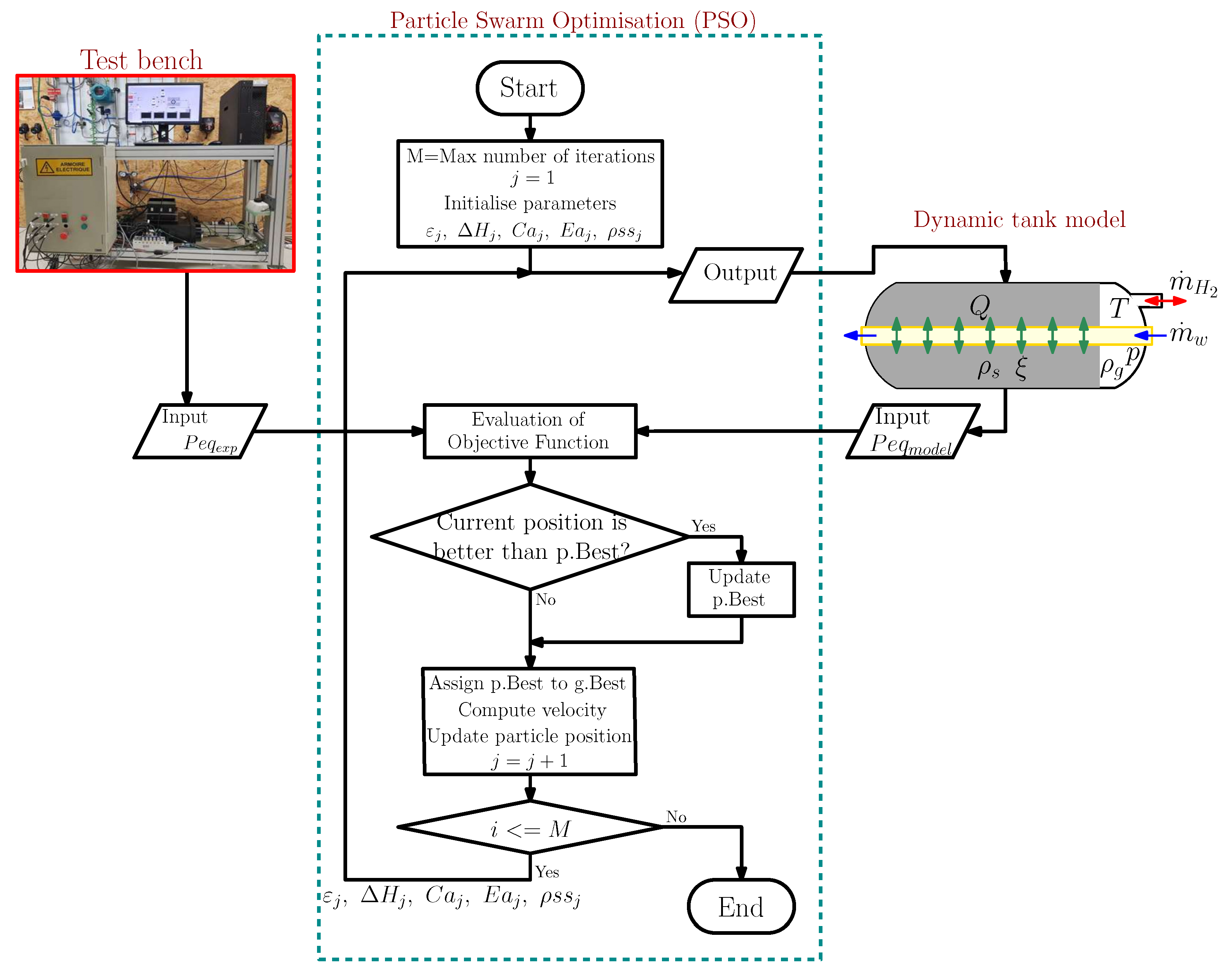
2. Modelling Process

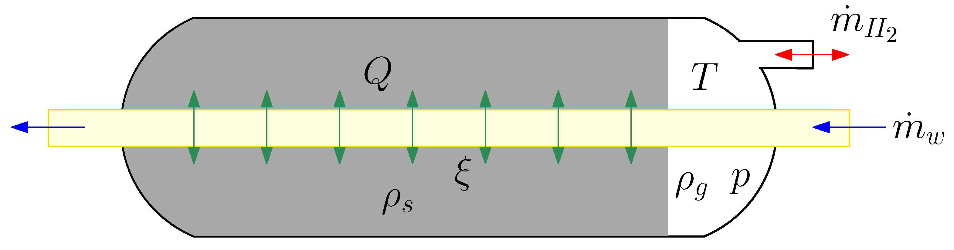
2.1. Dynamic Modelling of the Hydride Tank

To determine the internal parameters of the alloy, it is necessary to use a mathematical model to describe and simulate the behaviour of the hydrogen mass during the adsorption and desorption process, the reaction kinetics, equilibrium conditions, and the heat transfer. Different models are available in the scientific literature [22,23,24]. In this paper, the proposed model is based on the one developed by Chabane et al. [25]. A simplified section view of the hydride tank is illustrated in Figure 1. Its total length is 60 cm, its external diameter 13 cm, while the internal diameter is 11 cm. It contains inside 11.5 kg of alloy. It has a heat exchanger tube, with an external diameter of 1.2 cm.
The expression describing the reaction that takes place between the metal alloy and the hydrogen gas is described as follows [26]:
M + x 2 H 2 M H x + Δ H
where M denotes the metal alloy, M H x is the corresponding hydride, and x is the relation between the hydrogen and the metal. Lastly, Δ H is the heat of the reaction.
To simplify the model formulations, due to the complexity of the process, the following assumptions were made:
  • The gas phase behaves as a thermodynamically ideal gas.
  • The solid phase is isotropic and has a uniform porosity.
  • There is a thermal equilibrium between the gas and the solid particles.
  • The thermophysical properties are constant.
  • The equilibrium gas pressure is calculated by the Van’t Hoff equation.
A set of equations describing the phenomenon of mass and heat transfer when the medium is porous is presented in Table 1. They are based on the laws of conservation of mass, conservation of momentum, and conservation of energy.
Figure 2 presents the used mathematical derivation to extract the model of the absorption and desorption phenomena in a metal hydride tank starting from the equations given in Table 1.

2.2. Experimental Dynamic Tank Characterisation

Figure 3 shows the picture and the piping instrumentation diagram (PID) of the test bench used to characterise the metal hydride tanks. The test bench can quantify the thermal exchanges, allowing performing the thermal balance in relation to the absorption and/or desorption of the tank under test. In the dynamic characterisation, the hydrogen flow rate is kept constant, while the hydrogen supply pressure and the operating temperature of the metal hydride are left free. The quantities measured as a function of time are the pressure, temperature, and hydrogen flow rate of the container under test [34].

2.3. Identification of the Physical Parameters of The Model

This identification step completes the modelling process by calculating the physical parameters of the hydride tank model ( ξ , C a , E a , C d , E d , ρ s s , Δ H a b s , Δ H d e s ) . To obtain the best possible combination of values, the stochastic optimisation algorithm known as particle swarm optimisation (PSO) is used. This is a very powerful optimisation technique, which can be applied to a wide range of problems and situations. The notion was first suggested by Kennedy et al. in 1995 [35,36]. Since its origin, it has become one of the most successful techniques for solving global optimisation challenges. Its principle is based on the social and collaborative behaviour exhibited by different organisms such as birds, ants, termites, and even humans [37].
The intrinsic parameters to be determined include porosity ( ξ ) , as it reflects the number of interstitial sites relative to the total tank volume, which may affect the kinetics of the reaction. The enthalpy variation ( Δ H a b s , Δ H d e s ) refers to the amount of heat that needs to be supplied/extracted to make the reaction take place. The reaction rate constant ( C a , C d ) influences the time it takes to complete the absorption/desorption process. The saturation density ( ρ s s ) is directly related to the amount of stored hydrogen and affects the kinetics of the reaction as well. Finally, it is proposed to analyse the activation energy ( E a , E d ) , which establishes the energetic value necessary to establish the transition from one state to another in a reaction.
The set of parameters to be estimated is considered as an individual particle for the application of the optimisation algorithm. Therefore, the optimal particle position among a given set of options represents the results of parameter identification (Appendix A). An objective function is established to test the accuracy of the parameters. The value given by the function is the absolute relative error between the simulation results of the model and the actual operating data.
O b j e c t i v e F u n c t i o n : f o b j = m i n | P e q e x p P e q m o d e l | P e q e x p
Figure 4 presents the identification diagram used by applying the database acquired from the characterisation tests, the mathematical model, and the PSO algorithm [19].

3. Evaluation of Tank Performances in Healthy and Degraded States

3.1. Hydride Tank Used in a Real FCEV

In this section, the tank under study was integrated into the Mobypost vehicle in 2014; see Figure 5a,b [20,21]. During this period, this tank has been operated for several hundred hours and several charge/discharge cycles, which has affected its performance. To assess the degree of tank degradation, characterisation and modelling of the old tank (i.e., the degraded tank) recovered from the degraded vehicle were carried out. Data for the new tank (i.e., the healthy tank) have been available in our laboratory since the commissioning of the Mobypost vehicles six years ago.

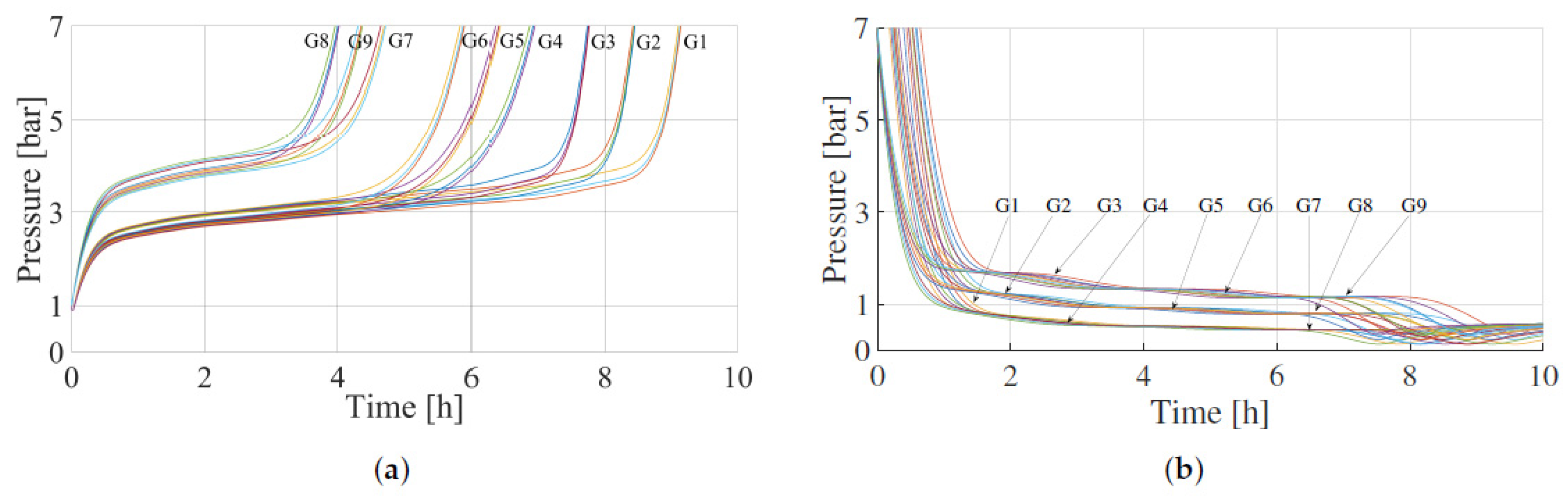
3.2. Results of the Experimental Dynamic Characterisation of the Tank

The hydrogen supplied/extracted during the two states studied (healthy, degraded) has a constant flow rate of 4 NL/min, at a pressure of 7 bar and a purity of 99.99%.
Figure 6a,b present the experimental values of pressure as a function of concentration and temperature versus time, respectively, for a metal hydride tank in its healthy state [38].
In Figure 7a,b, in the same way as for the healthy state, the experimental values of pressure versus concentration and temperature versus time, respectively, are presented for a metal hydride tank when it degrades [39].
Comparing qualitatively the pressure curve as a function of concentration in Figure 7a with the curve in Figure 6a shows a loss of reversible hydrogen storage capacity, a considerable increase in the slope of the plateau, and a reduction in the hysteresis between the absorption and desorption curve. A single, flat plateau is desirable since it allows complete hydrogen release when the system is maintained at constant pressure and temperature. In contrast, if the plateau is sloped or split, the pressure has to be reduced to extract all the hydrogen for a fixed temperature or, by analogy, at a constant pressure, the temperature has to be increased, which in practice has a negative impact.
By applying the same method of analysis and comparison of the two states of interest, a quantitative evaluation of the experimental data obtained can be performed, based on equations that allow the determination of different parameters such as equilibrium pressures, hysteresis, and gravimetric capacity.
P a b s = P p a b s n ( P p a b s = p l a t e a u p r e s s u r e i n t h e a b s o r p t i o n p r o c e s s )
P d e s = P p d e s n ( P p d e s = p l a t e a u p r e s s u r e i n t h e d e s o r p t i o n p r o c e s s )
H y s = l n P a b s P d e s
m H 2 = 0 t m ˙ H 2 d t
w t % = m H 2 ( m M H + m H 2 ) 100
where P d e s and P a b s are the average pressure of the plateau for desorption and absorption, respectively, n is the number of plateau points, and H y s is defined as hysteresis, a phenomenon that occurs between the adsorption and desorption equilibrium pressures. m H 2 is the mass of hydrogen stored or extracted; m ˙ H 2 is the hydrogen flow rate, which for this test is 4 Nl/min; m M H is the mass of the alloy (11.5 kg); w t % is the gravimetric capacity.
Examining the data obtained for the initial state of the commercial metal hydride tank, it was determined that the equilibrium pressure for the absorption process is 3.06 bar, while for the desorption process, an equilibrium pressure of 1.47 bar is established, giving a value of 0.75 as the hysteresis, with an average tank temperature of 21 ° C. The hydrogen stored was 177 g, giving a gravimetric capacity of 1.52%.
A similar analysis to the one carried out for the initial state can be made for the intermediate state where a quantity of stored hydrogen of 92 g is determined, which gives a gravimetric capacity of 0.8%. The equilibrium pressure for the absorption process is 3.77 bar, while for the desorption process, the equilibrium pressure is 2.26 bar, and a minor hysteresis of 0.51 bar is established; the average tank temperature is 21 ° C. In order to combine all the results obtained and to facilitate the evaluation, Table 2 is given, where a summary of the parameters in each state studied is given.
It can be concluded that, quantitatively and qualitatively, a variation of the equilibrium pressure and gravimetric storage capacity is observed between the two different states of the same metal hydride tank. It is desired to know the state of some intrinsic parameters of the tank and to observe whether they also present a certain variation. Therefore, it is necessary to estimate the intrinsic parameters of the metal hydride in both states without knowing the alloy composition.

3.3. Result of the Identification of the Model’s Physical Parameters

Table 3 presents the results obtained by performing the identification diagram of Figure 4 on the test results shown in Figure 6a,b or Figure 7a,b.
Analysing the results obtained, a decrease in the porosity ( ξ ) is observed, which implies an expansion of the alloy inside the tank. A reduction in the reaction constant ( C a , C d ) can be appreciated, which has a direct impact on the time in which the reaction is carried out for both the absorption and desorption processes. There is a significant variation in the value of the enthalpy variation ( Δ H a b s , Δ H d e s ) , which translates into the requirement of a greater amount of heat to be supplied to ensure the desorption process, and inversely a greater amount of heat to be extracted to ensure the absorption process. The saturation density ( ρ s s ) decreased, which is in line with the decrease in gravimetric capacity. Finally, there is no significant variation in the activation energy ( E a , E d ) , so it is considered constant and unchanging.
To check the validity of the two tank models in the healthy and degraded states, the pressure concentration temperature (PCT) curves corresponding to each modelling case are grouped in Figure 8. A very good concordance is observed in the curves obtained by the simulation and the experimental data, which allows validating the estimated parameters, as well as the developed models.
These curves show the variation of the tank performance in terms of concentration and pressure plateau slope. The concentration reflects the hydrogen absorption capacity of the tank, while the slope of the pressure plateau reflects proportionally the kinetics of hydrogen absorption and desorption. Indeed, the healthy tank has a maximum storage capacity of 1.5 % and fast kinetics, while the degraded tank is characterised by a concentration drop of up to 0.8 % and slower kinetics.

4. Correlation between Tank Degradation and Model Physical Parameters

To identify the sensitivity of the proposed model to the change in the intrinsic parameters of the metal hydride, different possible scenarios were studied where a combination of parameters was realised. For this purpose, it was decided to take into consideration the parameters that show a greater change from the healthy state to the degraded state in Table 4. Therefore, the porosity ( ξ ) was taken into consideration taking the values of [ 0.5 , 0.42 , 0.35 ] , as well as the enthalpy variation ( Δ H a b s , Δ H d e s ) with the values of [31,600, 20,000, 6700] and [31,600, 22,700, 13,800], respectively; finally, the saturation density ( ρ s s ) with the values of [ 8473 , 8455 , 8446 ] was taken into consideration.
Figure 9, Figure 10 and Figure 11 present the simulations of the different combinations proposed in the table for the pressure, temperature, and gravimetric capacity of a metal hydride tank when it is submitted to the absorption and desorption processes. It is important to note that the supplied/requested hydrogen flow rate according to the process is the same as the one presented in Section 3.2 of 4 Nl/min.
Analysing the impact of the enthalpy variation in the different graphs, it is possible to see that the pressure increases when the enthalpy variation ( Δ H a b s , Δ H d e s ) decreases; it can also be observed that the tank temperature is lower when the enthalpy value is lower in absolute values. A reduction in the enthalpy variation translates at the system level into the need to provide a greater amount of heat to ensure the reaction, which implies a greater energy consumption. On the other hand, it is observed that decreasing the saturation density ( ρ s s ) of the metal hydride results in a lower gravimetric capacity, which translates into a lower amount of hydrogen stored or supplied.
Looking at the porosity ( ξ ) , knowing that the volume of the tank is constant and invariable, when the porosity is high, the adsorption or desorption process ends earlier, which means that they have a fast reaction kinetics. On the other hand, when the metal has a low porosity, the processes are slower, resulting in slower kinetics.
These simulation results clearly show that there is a strong correlation between, on the one hand, the performance of the tank under study, in terms of gravimetric capacity and hydrogen charge/discharge kinetics, and on the other hand, three physical parameters of the tank model, namely the saturation density ( ρ s s ) , the porosity ( ξ ) , and the enthalpy variation ( Δ H a b s , Δ H d e s ) . Thus, the development of the laws of variation of these parameters according to the real conditions of use of the FCEVs (number of charging/discharging cycles, pressures, mass flow rates, temperatures) can help to predict tank degradation.
As mentioned in the introductory part, the causes of the degradation process, as well as the variation of the internal parameters have been studied by the scientific community, and some possible hypotheses have been proposed to justify this phenomenon. The reasons can be extrinsic or intrinsic [11]. The first ones are easily mitigated by an adequate adjustment of the external conditions such as hydrogen quality or by avoiding high working temperatures. Furthermore, intrinsic degradation is difficult to eliminate and remains a major research challenge, such as disproportionation [13], amorphisation [14], generation of stable phases [10], or oxidation, among others [5,9,17,18].

5. Conclusions

This paper presents an investigation of the effect of charge/discharge cycles on the performance of a metal hydride hydrogen storage system that fed a real FCEV. A mathematical model describing mass and energy transfer phenomena during the adsorption and desorption processes was proposed based on unknown physical parameters such as porosity, reaction constants, enthalpy variations, saturation density, and activation energies. The identification of these parameters was carried out by implementing the well-known PSO algorithm combined with a series of experimental results in the metal hydride tank. The proposed model has a maximum relative error compared to the experimental measurements less than 2 % .
The qualitative and quantitative analysis of the experimental results performed on the metal hydride tank in the healthy and degraded state revealed a strong correlation between the gravimetric capacity and hydrogen charge/discharge kinetics of the tank and three physical parameters of the tank model, namely the saturation density ( ρ s s ) , the porosity constant ( ξ ) , and the enthalpy ( Δ H a b s , Δ H d e s ) . A simulation study was carried out using 27 different combinations of these parameters in order to show the variations in the pressure, temperature, and gravimetric capacity of the tank when it is subjected to the absorption and desorption processes. The results obtained confirm the correlation revealed above and demonstrate that it is possible to predict tank degradations by developing laws of the variation of the physical parameters of the tank model as a function of the real conditions of use of the FCEVs (number of charging/discharging cycles, pressures, mass flow rates, temperatures).

Author Contributions

Conceptualization, S.H.S., D.C. and A.D.; methodology, S.H.S. and D.C.; software, S.H.S.; validation, S.H.S. and D.C.; investigation, S.H.S.; data curation, S.H.S.; writing—original draft preparation, S.H.S.; writing—review and editing, D.C., Y.A.-A., A.N., O.E. and A.D.; supervision, A.D.; project administration, A.D.; funding acquisition, A.D. All authors have read and agreed to the published version of the manuscript.

Funding

This work was supported by the EIPHI Graduate School (Contract ANR-17-EURE-0002) and the Region Bourgogne Franche-Comté within the framework of the DHyPAC project.

Institutional Review Board Statement

Not applicable.

Informed Consent Statement

Not applicable.

Data Availability Statement

The data presented in this study are available on request from the corresponding author.

Acknowledgments

The Moby-Post project is funded under Grant Agreement No. 256834 by the European Union seventh Framework program (FP7/2007e2013) for the Fuel Cell and Hydrogen Joint Technology Undertaking.

Conflicts of Interest

The authors declare no conflict of interest. The funders had no role in the design of the study; in the collection, analyses, or interpretation of the data; in the writing of the manuscript; nor in the decision to publish the results.

Nomenclature

Physics Constants
ξ Porosity of MH
ρ Density ( kg / m 3 )
H / M Hydrogen atoms per metal atom
k r Hydrogen kinetics ( kg / ( s m 3 ) )
RUniversal gas constant ( 8.315 ( J / mol K ) )
C p Specific heat capacity ( J / kg / K )
TTemperature ( K )
K u Heat transfer coefficient ( W / m / K )
M H 2 Hydrogen molar mass ( kg / mol )
Δ H Enthalpy of reaction ( J / mol )
Δ S Entropy of reaction ( J / ( K mol ) )
PPressure ( bar )
CConstant rate ( 1 / s )
EActivation energy ( J / mol )
QHeat flow ( W )
tTime ( s )
DDiameter ( m )
LLength ( m )
VVolume ( m 3 )
mMass ( kg )
m ˙ Mass flow rate ( kg / s )
V ˙ Volume flow rate ( Nl / min )
Subscripts
aAbsorption
e q Equilibrium
gGas
sSolid
i n Inlet
o u t Outlet
M H Metal hydride
MMetal
R e f Reference
0Empty
wWater

Appendix A

Generally, the algorithm is composed of the position update formula (Equation ( a ) of Figure A1) and the velocity update formula (Equation ( b ) of Figure A1) [35]. For each particle in the population M, the position and velocity information are updated by iterating with regard to its own best historical solution ( ϱ b e s t ) and the best global value ( σ b e s t ) [36].
Five steps are necessary to achieve the optimisation of the population values [40]:
A: Initialise the population randomly inside a search space. Establish the maximal iteration number, the size of the population, the cognitive factors, the social factors, the limits of position, and the maximum speed limit.
B: Compute the aptitude of each particle based on the fitness function.
C: Compare the performance of each particle with the historical best solution ( ϱ b e s t ) . If it turns out to be a smaller value, ϱ b e s t is reassigned; otherwise, no modification of ϱ b e s t is performed. In the same way, the aptitude is compared with the global best solution ( σ b e s t ) applying the same criteria.
D: Use Equations ( a ) and ( b ) to actualise the position and speed of the particles, ensuring that they respect the boundaries set.
E: Verify if the theoretical optimum is achieved, then output the value, and stop the operation; if not, go back to B until the theoretical optimum or maximum number of iterations is achieved.
Figure A1. Optimisation strategy of the PSO algorithm. χ m j is the initial particle position; χ m j + 1 is the new position; ν m j is the current velocity of the particle; ν m j + 1 is the speed after being influenced by different aspects (influence of the particle and swarm memory).
Energies 15 03484 g0a1

References

  1. Xin, G.; Yuan, H.; Yang, K.; Jiang, L.; Liu, X.; Wang, S. Promising hydrogen storage properties of cost-competitive La(Y)–Mg–Ca–Ni AB3-type alloys for stationary applications. RSC Adv. 2016, 6, 21742–21748. [Google Scholar] [CrossRef]
  2. Yang, C.C.; Wang, C.C.; Li, M.M.; Jiang, Q. A start of the renaissance for nickel metal hydride batteries: A hydrogen storage alloy series with an ultra-long cycle life. J. Mater. Chem. A 2017, 5, 1145–1152. [Google Scholar] [CrossRef]
  3. Manzetti, S.; Mariasiu, F. Electric vehicle battery technologies: From present state to future systems. Renew. Sustain. Energy Rev. 2015, 51, 1004–1012. [Google Scholar] [CrossRef]
  4. Joseph, B.; Iadecola, A.; Schiavo, B.; Cognigni, A.; Olivi, L.; Saini, N.L. Large atomic disorder in nanostructured LaNi5 alloys: A La L3-edge extended X-ray absorption fine structure study. J. Phys. Chem. Solids 2010, 71, 1069–1072. [Google Scholar] [CrossRef] [Green Version]
  5. Balogun, M.S.; Wang, Z.M.; Chen, H.X.; Deng, J.Q.; Yao, Q.R.; Zhou, H.Y. Effect of Al content on structure and electrochemical properties of LaNi4.4-xCo0.3Mn0.3Alx hydrogen storage alloys. Int. J. Hydrogen Energy 2013, 38, 10926–10931. [Google Scholar] [CrossRef]
  6. Wjihi, S.; Sellaoui, L.; Bouzid, M.; Dhaou, H.; Knani, S.; Jemni, A.; Ben Lamine, A. Theoretical study of hydrogen sorption on LaNi5 using statistical physics treatment: Microscopic and macroscopic investigation. Int. J. Hydrogen Energy 2017, 42, 2699–2712. [Google Scholar] [CrossRef]
  7. Chabane, D.; Harel, F.; Djerdir, A.; Ibrahim, M.; Candusso, D.; Elkedim, O.; Fenineche, N. Influence of the key parameters on the dynamic behaviour of the hydrogen absorption by LaNi5. Int. J. Hydrogen Energy 2017, 42, 1412–1419. [Google Scholar] [CrossRef] [Green Version]
  8. Dhaou, M.H.; Belkhiria, S.; Sdiri, N.; Mallah, A.; Al-Thoyaib, S.; Jemni, A.; Ben Nasrallah, S. Thermodynamic and electric study of the LaNi3,6Al0,4Co0,7Mn0,3 alloy. Int. J. Hydrogen Energy 2017, 42, 2209–2214. [Google Scholar] [CrossRef]
  9. Borzone, E.M.; Blanco, M.V.; Baruj, A.; Meyer, G.O. Stability of LaNi5-xSnx cycled in hydrogen. Int. J. Hydrogen Energy 2014, 39, 8791–8796. [Google Scholar] [CrossRef]
  10. Spodaryk, M.; Shcherbakova, L.; Sameljuk, A.; Wichser, A.; Zakaznova-Herzog, V.; Holzer, M.; Braem, B.; Khyzhun, O.; Mauron, P.; Remhof, A.; et al. Description of the capacity degradation mechanism in LaNi5-based alloy electrodes. J. Alloys Compd. 2015, 621, 225–231. [Google Scholar] [CrossRef]
  11. Pinatel, E.R.; Palumbo, M.; Massimino, F.; Rizzi, P.; Baricco, M. Hydrogen sorption in the LaNi5-xAlx-H system (0 ≤ x ≤ 1). Intermetallics 2015, 62, 7–16. [Google Scholar] [CrossRef]
  12. Luo, S.; Clewley, J.D.; Flanagan, T.B.; Bowman, R.C.; Cantrell, J.S. Split Plateaux in the LaNi5–H System and the Effect of Sn Substitution on Splitting. J. Alloys Compd. 1997, 253–254, 226–231. [Google Scholar] [CrossRef]
  13. Zhu, H.Y.; Wu, J.; Wang, Q.D. Disproportionation of LaNi5 and TiFe in 4 MPa H2 at 300 °C. J. Alloys Compd. 1992, 185, 1–6. [Google Scholar] [CrossRef]
  14. Han, J.; Lee, J.Y. An investigation of the intrinsic degradation mechanism of LaNi5 by thermal desorption technique. Int. J. Hydrogen Energy 1988, 13, 577–581. [Google Scholar] [CrossRef]
  15. Benham, M.J.; Ross, D.K.; Lartigue, C.; Percheron-Guégan, A. Inelastic Neutron Scattering Studies of Multiply Cycled Lanthanum-Nickel Hydride*. Z. Für Phys. Chem. 1986, 147, 219–229. [Google Scholar] [CrossRef]
  16. Wan, C.; Ju, X.; Qi, Y.; Zhang, Y.; Wang, S.; Liu, X.; Jiang, L. Synchrotron XRD and XANES studies of cerium-doped NaAlH4: Elucidation of doping induced structure changes and electronic state. J. Alloys Compd. 2009, 481, 60–64. [Google Scholar] [CrossRef]
  17. Peng, X.; Liu, B.; Fan, Y.; Zhu, X.; Peng, Q.; Zhang, Z. Microstructures and electrochemical hydrogen storage characteristics of La0.7Ce0.3Ni4.2Mn0.9-xCu0.37(Fe0.43B0.57)x (x = 0–0.20) alloys. J. Power Sources 2013, 240, 178–183. [Google Scholar] [CrossRef]
  18. Casini, J.C.S.; Silva, F.M.; Guo, Z.P.; Liu, H.K.; Faria, R.N.; Takiishi, H. Effects of substituting Cu for Sn on the microstructure and hydrogen absorption properties of Co-free AB5 alloys. Int. J. Hydrogen Energy 2016, 41, 17022–17028. [Google Scholar] [CrossRef]
  19. Zhu, D.; Ait-Amirat, Y.; N’Diaye, A.; Djerdir, A. New dynamic modeling of a real embedded metal hydride hydrogen storage system. Int. J. Hydrogen Energy 2019, 44, 29203–29211. [Google Scholar] [CrossRef]
  20. Higel, C.; Harel, F.; Candusso, D.; Faivre, S.; Ravey, A.; Guilbert, D.; N’diaye, A.; Gaillard, A.; Bouquain, D.; Djerdir, A.; et al. Part 1: Mobypost vehicle’s powertrain modeling, simulation and sizing. In Proceedings of the 5th International Conference on Fundamentals and Development of Fuel Cells, Karlsruhe, Germany, 15–17 April 2013; p. 2357414. [Google Scholar]
  21. Faivre, S.; Ravey, A.; Guilbert, D.; Ndiaye, A.; Gaillard, A.; Bouquain, D.; Djerdir, A.; Higel1, C.; Harel, F.; Candusso, D. Part 2—Mobypost vehicle’s powertrain desing and experimental validation. In Proceedings of the 5th International Conference on Fundamentals and Development of Fuel Cells, Karlsruhe, Germany, 15–17 April 2013. [Google Scholar]
  22. Sakintuna, B.; Lamari-Darkrim, F.; Hirscher, M. Metal hydride materials for solid hydrogen storage: A review. Int. J. Hydrogen Energy 2007, 32, 1121–1140. [Google Scholar] [CrossRef]
  23. Ren, J.; Musyoka, N.M.; Langmi, H.W.; Mathe, M.; Liao, S. Current research trends and perspectives on materials-based hydrogen storage solutions: A critical review. Int. J. Hydrogen Energy 2017, 42, 289–311. [Google Scholar] [CrossRef]
  24. Liu, J.; Zheng, Z.; Cheng, H.; Li, K.; Yan, K.; Han, X.; Wang, Y.; Liu, Y. Long-term hydrogen storage performance and structural evolution of LaNi4Al alloy. J. Alloys Compd. 2018, 731, 172–180. [Google Scholar] [CrossRef]
  25. Chabane, D.; Harel, F.; Djerdir, A.; Candusso, D.; Elkedim, O.; Fenineche, N. Energetic modeling, simulation and experimental of hydrogen desorption in a hydride tank. Int. J. Hydrogen Energy 2019, 44, 1034–1046. [Google Scholar] [CrossRef]
  26. Afzal, M.; Mane, R.; Sharma, P. Heat transfer techniques in metal hydride hydrogen storage: A review. Int. J. Hydrogen Energy 2017, 42, 30661–30682. [Google Scholar] [CrossRef]
  27. Tong, L.; Xiao, J.; Yang, T.; Bénard, P.; Chahine, R. Complete and reduced models for metal hydride reactor with coiled-tube heat exchanger. Int. J. Hydrogen Energy 2019, 44, 15907–15916. [Google Scholar] [CrossRef]
  28. Busqué, R.; Torres, R.; Grau, J.; Roda, V.; Husar, A. Effect of metal hydride properties in hydrogen absorption through 2D-axisymmetric modeling and experimental testing in storage canisters. Int. J. Hydrogen Energy 2017, 42, 19114–19125. [Google Scholar] [CrossRef] [Green Version]
  29. Busqué, R.; Torres, R.; Grau, J.; Roda, V.; Husar, A. Mathematical modeling, numerical simulation and experimental comparison of the desorption process in a metal hydride hydrogen storage system. Int. J. Hydrogen Energy 2018, 43, 16929–16940. [Google Scholar] [CrossRef] [Green Version]
  30. Mellouli, S.; Ben Khedher, N.; Askri, F.; Jemni, A.; Ben Nasrallah, S. Numerical analysis of metal hydride tank with phase change material. Appl. Therm. Eng. 2015, 90, 674–682. [Google Scholar] [CrossRef]
  31. Askri, F.; Ben Salah, M.; Jemni, A.; Ben Nasrallah, S. Optimization of hydrogen storage in metal-hydride tanks. Int. J. Hydrogen Energy 2009, 34, 897–905. [Google Scholar] [CrossRef]
  32. Abdin, Z.; Webb, C.J.; Gray, E.M.A. One-dimensional metal-hydride tank model and simulation in Matlab–Simulink. Int. J. Hydrogen Energy 2018, 43, 5048–5067. [Google Scholar] [CrossRef]
  33. Chaise, A.; De Rango, P.; Marty, P.; Fruchart, D. Experimental and numerical study of a magnesium hydride tank. Int. J. Hydrogen Energy 2010, 35, 6311–6322. [Google Scholar] [CrossRef]
  34. Suárez, S.; Chabane, D.; N’Diaye, A.; Ait-Amirat, Y.; Djerdir, A. Static and dynamic characterization of metal hydride tanks for energy management applications. Renew. Energy 2022, 191, 59–70. [Google Scholar] [CrossRef]
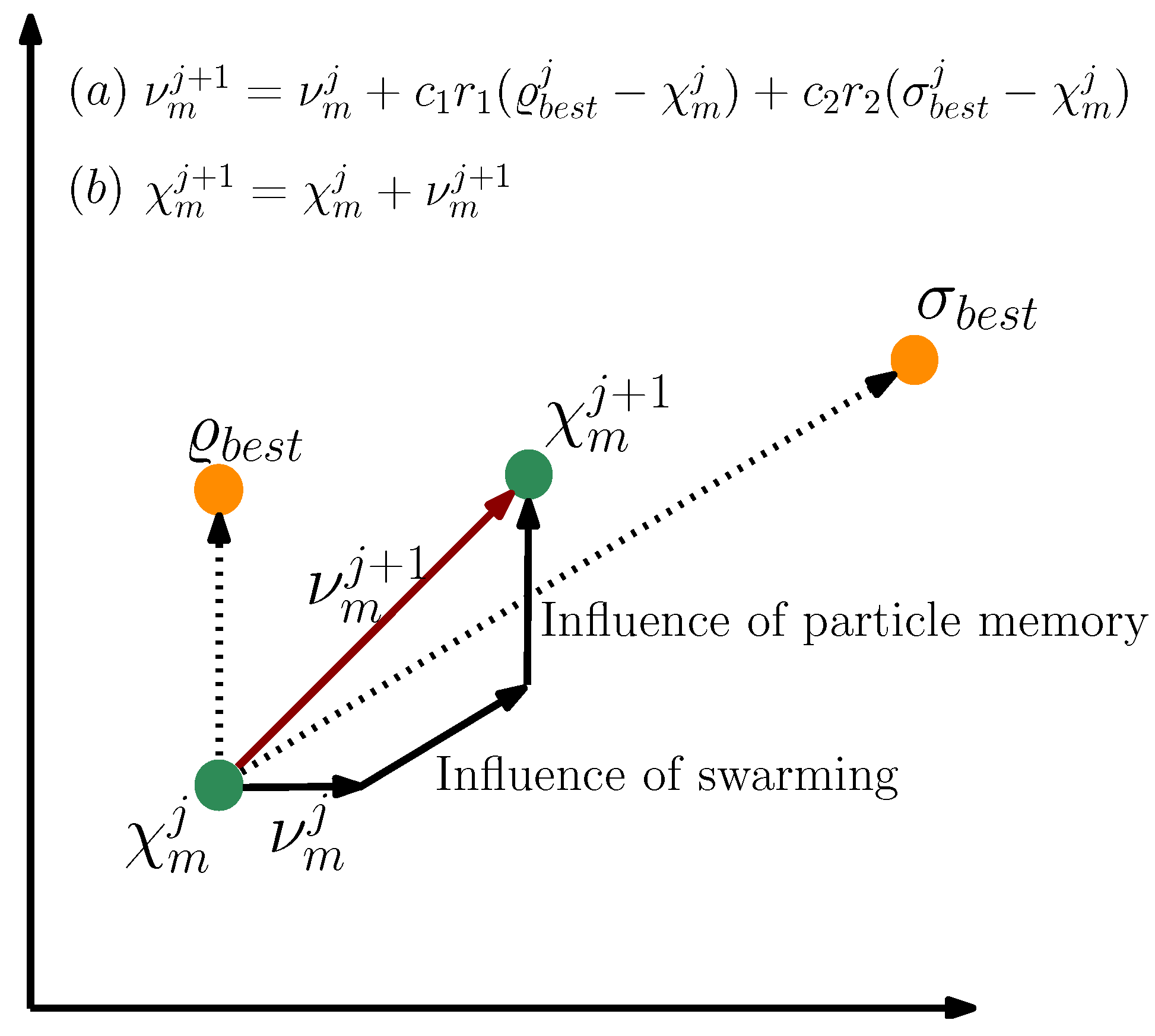
  35. Kennedy, J.; Eberhart, R. Particle swarm optimization. In Proceedings of the ICNN’95—International Conference on Neural Networks, Perth, WA, Australia, 27 November–1 December 1995; Volume 4, pp. 1942–1948. [Google Scholar] [CrossRef]
  36. Kennedy, J. Particle swarm: Social adaptation of knowledge. In Proceedings of the IEEE Conference on Evolutionary Computation, (ICEC 1997), Indianapolis, IN, USA, 3–16 April 1997; pp. 303–308. [Google Scholar] [CrossRef]
  37. Storn, R. Differrential evolution—A simple and efficient adaptive scheme for global optimization over continuous spaces. Tech. Rep. Int. Comput. Sci. Inst. 1995, 11, 341–359. [Google Scholar]
  38. Chabane, D.; Harel, F.; Djerdir, A.; Candusso, D.; ElKedim, O.; Fenineche, N. A new method for the characterization of hydrides hydrogen tanks dedicated to automotive applications. Int. J. Hydrogen Energy 2016, 41, 11682–11691. [Google Scholar] [CrossRef]
  39. Suarez, S.H.; Chabane, D.; N’Diaye, A.; Ait-Amirat, Y.; Djerdir, A. Dynamic and Static characterization of the absorption process in metal hydride tanks for Mobile Applications. In Proceedings of the 2021 IEEE Vehicle Power and Propulsion Conference, VPPC 2021-Proceeding, Gijón, Spain, 25 October–14 November 2021. [Google Scholar] [CrossRef]
  40. Shi, Y.; Eberhart, R.C. Empirical study of particle swarm optimization. In Proceedings of the 1999 Congress on Evolutionary Computation-CEC99, Washington, DC, USA, 6–9 July 1999; Volume 3, pp. 1945–1950. [Google Scholar] [CrossRef]
Figure 1. Synoptic model.
Energies 15 03484 g001
Figure 2. Derivation of the dynamic tank model from the equations in the Table 1.
Energies 15 03484 g002
Figure 3. Picture (left) and PID (right) of the test bench.
Energies 15 03484 g003
Figure 4. Diagram of physical parameter identification.
Energies 15 03484 g004
Figure 5. (a) Metal hydride tank studied; (b) FCEV Mobypost vehicle [20].
Energies 15 03484 g005
Figure 6. Healthy state of the tank: (a) Pressure versus concentration, (b) Temperature versus time [38].
Energies 15 03484 g006
Figure 7. Degraded state of the tank: (a) Pressure versus concentration, (b) Temperature versus time.
Energies 15 03484 g007
Figure 8. Experimental and model PCT at 21 ° C in healthy and degraded tank states.
Energies 15 03484 g008
Figure 9. Pressure as a function of time: (a) Absorption process, (b) Desorption process.
Energies 15 03484 g009
Figure 10. Temperature as a function of time: (a) Absorption process, (b) Desorption process.
Energies 15 03484 g010
Figure 11. Gravimetric capacity as a function of time: (a) Absorption process, (b) Desorption process.
Energies 15 03484 g011
Table 1. Equations of the dynamic tank model.
DefinitionEquationRef.
Mass balance for the gas V t a n k V M H 1 + ξ d ρ g d t = k r ± m ˙ H 2 V M H [27]
Mass balance for the metal alloy ( 1 ξ ) d ρ s d t = k r [28]
Kinetics of the process C a e x p E a T M H R l n P g P e q ( ρ s s ρ s ) [29]
C d e x p E d T M H R P g P e q P e q ( ρ s ρ 0 ) [29]
Equilibrium pressure l n P e q P 0 = Δ H T M H R + Δ S T M H [30]
Experimental equilibrium pressure P e q = f w t % e x p | Δ H | R 1 T M H 1 T r e f [31]
Mass of hydrogen m H 2 = 0 t m ˙ H 2 d t [25]
Gravimetric storage capacity w t % = m H 2 ( m M H + m H 2 ) 100 [32]
Energy balance ξ ρ g C p g + ( 1 ξ ) ρ s C p s d T M H d t = ± Q ± k r Δ H M H 2 [33]
Heat exchanged Q = m ˙ w C p w V M H ( T w i n T M H ) ( 1 e K u π D L m ˙ w C p w ) [25]
Table 2. A summary of the parameters extracted from Figure 6a,b or Figure 7a,b.
ParameterHealthy StateDegraded StateVariation (%)Unit
Pabs3.063.7723.2bar
Pdes1.472.2653.7bar
Hysteresis0.750.51−32
Temperature21210 ° C
Concentration1.520.81−47.4%
Table 3. Comparison of tank parameters.
ParametersRangeState Variation (%)Units
HealthyDegraded
ε [0.2, 0.7]0.50210.355329.3-
C a [40, 70]58.02043.85824.41/s
E a [20, 22]20.98920.6811.4kJ/mol
C d [7, 10]9.9707.99619.81/s
E d [15, 20]16.51016.1931.9kJ/mol
ρ s s [8400, 8600]847384460.31kg/m3
Δ H a b s [6000, 36,000]−31,660−675378.5J/mol
Δ H d e s [6000, 36,000]31,80013,85656.4J/mol
Simulation error<2.51.80951.503-%
Table 4. Possible combinations for the variation of parameters.
AbsorptionDesorptionSimulation Groups
ρ ss (kg/m3) ξ Δ H (J/mol) ρ ss (kg/m3) ξ Δ H (J/mol)
84700.4530,00084700.4530,000G1
20,00022,000
10,00014,000
0.4030,0000.4030,000G2
20,00022,000
10,00014,000
0.3530,0000.3530,000G3
20,00022,000
10,00014,000
84600.4530,00084600.4530,000G4
20,00022,000
10,00014,000
0.4030,0000.4030,000G5
20,00022,000
10,00014,000
0.3530,0000.3530,000G6
20,00022,000
10,00014,000
84500.4530,00084500.4530,000G7
20,00022,000
10,00014,000
0.4030,0000.4030,000G8
20,00022,000
10,00014,000
0.3530,0000.3530,000G9
20,00022,000
10,00014,000
Publisher’s Note: MDPI stays neutral with regard to jurisdictional claims in published maps and institutional affiliations.

